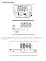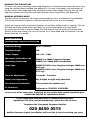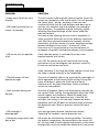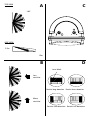
1
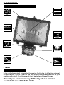
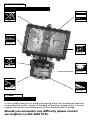
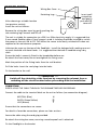
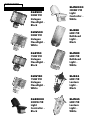
SLB500-Black/SLW500-White
150W PIR HALOGEN
FLOODLIGHT
SLB150-Black/SLW150-White
INSTALLATION & OPERATING
INSTRUCTIONS
500W PIR HALOGEN
FLOODLIGHT
SLB500/SLW500
500W PIR HALOGEN FLOODLIGHT
WEATHERPROOF
LAMP TYPE
500w
IP44
MAXIMUM
PIR SWITCHING
2000w
MAXIMUM
MANUAL ON/OFF
OVERRIDE
TIME ON
5sec
5min
DETECTION ANGLE
ADJUSTABLE
140°
ADJUSTABLE
DUSK TO DAWN
DETECTION RANGE
ADJUSTABLE
12m
ADJUSTABLE
3 YEAR
GUARANTEE
In the unlikely event of this product becoming faulty due to defective material
or manufacture, within 3 years of the date of purchase, please return it to your
supplier with proof of purchase and it will be replaced free of charge.
Should you encounter any difficulty please contact
our helpline on 020 8450 0515.
SLB150/SLW150
150W PIR HALOGEN FLOODLIGHT
WEATHERPROOF
LAMP TYPE
150w
IP44
MAXIMUM
PIR SWITCHING
2000w
MAXIMUM
MANUAL ON/OFF
OVERRIDE
TIME ON
5sec
5min
DETECTION ANGLE
ADJUSTABLE
140°
ADJUSTABLE
DUSK TO DAWN
DETECTION RANGE
ADJUSTABLE
12m
ADJUSTABLE
3 YEAR
GUARANTEE
In the unlikely event of this product becoming faulty due to defective material
or manufacture, within 3 years of the date of purchase, please return it to your
supplier with proof of purchase and it will be replaced free of charge.
Should you encounter any difficulty please contact
our helpline on 020 8450 0515.
SECTION ONE
GENERAL INFORMATION
The unit utilises passive infrared technology to detect heat radiation of moving human bodies.
Upon detection, the lamp will illuminate for a user-determined time period.
An integral daylight sensor ensures night-only operation.
PARTS INCLUDED
- Luminaire c/w PIR Sensor unit.
- Instruction manual. Please keep safe for future reference.
- Accessory Pack.
- Tungsten halogen bulb
TOOLS & PARTS NEEDED
- Electric/hand-held drill & bits.
- Terminal or Electricians screwdriver
- Large slotted/philips screwdriver
- Wire cutters
Unit is for outdoor use only. Unit must be mounted on a non-flammable surface as a fixed
luminaire, and is not suitable for portable use.
The unit can get very hot during use. Ensure the unit has cooled before handling.
Ensure adequate ventilation space is allowed between the unit and any object above, in front or
to either side of the unit. Suggested space is 0.5m above, 0.3m to either side & 1.0m in front.
If in any doubt, consult a qualified tradesperson or electrician.
SECTION TWO
SELECTING THE LOCATION
The motion detector has a number of detection zones, at various vertical and horizontal
angles as shown (see diagram A).
A moving human body needs to cross/enter one of these zones to activate the sensor. The
best all-round coverage is achieved with the unit mounted at the optimum height of 2.5m.
Careful positioning of the sensor will be required to ensure optimum performance. See
diagram A detailing detection range and direction.
The sensor is more sensitive to movement ACROSS its field of vision than to movement
directly TOWARDS (see diagram B). Therefore position the unit so that the sensor looks
ACROSS the likely approach path.
Avoid positioning the sensor where there are any sources of heat in the detection area
(extractor fans, tumble dryer exhausts etc.).
Reflective surfaces (ie pools of water or white-painted walls) and overhanging branches may
cause false activation under extreme conditions.
During extreme weather conditions the motion sensor may exhibit unusual behaviour. This
does not indicate a fault with the sensor. Once normal weather conditions return, the
sensor will resume normal operation.
SECTION THREE
INSTALLATION
Wiring Box Cover
Retaining Lugs
After choosing a suitable location
(see previous section)
install the unit as follows:
Insert small
screwdriver
and gently
push and lift
cover off.
Remove the wiring box cover by gently pushing the
side retaining lugs inwards and lift off.
The unit is suitable for connection to a 230 V ac 50Hz electricity supply. It is suggested that
3-core round flexible cable of 1mm2 gauge is used. A isolating should be installed to switch
the power to the unit ON & OFF. This allows the sensor to be easily switched off when not
required or for maintenance purposes.
Unfasten the screw on the top of the floodlight. Install the halogen bulb, making sure not
to touch the bulb with bare hands. It is suggested that the bulb is handled using a dry
cloth.
Ensure the bulb is correctly fitted in the lampholder before use.
Re-attach the front cover, do not overtighten the fixing screw.
Mark the position of the fitting holes from the wall bracket.
Drill the holes. Insert the rawl plugs into the holes.
Fix the bracket to the wall.
*** IMPORTANT ***
Switch off the electricity at the fuse box by removing the relevant fuse or
switching off the circuit breaker before proceeding with the installation.
CONNECTION
PIERCE & PASS THE CABLE THROUGH THE GROMMET BEFORE PROCEEDING.
Connect the cable to the terminal block on the unit as follows (see connection diagram):
NEUTRAL (Blue)
EARTH (Green/Yellow)
LIVE (Brown)
N
L
Ensure that the connections are secure.
For details of override connections, please see later sections.
Secure the cable using the cord grip provided.
Re-attach the wiring box cover, ensuring a weatherproof seal is obtained.
Fix the floodlight to the bracket
CONNECTION DIAGRAM
Mains
Supply
Isolation
Switch
The diagram below also shows the required connections for the addition of slave luminaires.
When adding slaves, be sure not to exceed the maximum switchable load (see Technical
Specifications).
SECTION FOUR
OPERATION AND TESTING
WALK TEST PROCEDURE
The sensor will rotate from left to right, and tilt forward or backward. Adjust the sensor to
point in the required direction.
The unit can be set up in daylight or at night.
Set the time adjustment to minimum (fully anti-clockwise).
Turn the power to the unit on. The lamp will illuminate for approximately 30 seconds. This
indicates the unit is wired correctly.
After approximately 30 seconds the light will turn off.
The unit is now in Test Mode.
TEST MODE
The lamp will now illuminate for approximately 5 seconds every time movement is detected.
Walk across the detection area approximately 5 metres from the unit. Each time you are
detected the lamp will illuminate. Now stand still until the lamp extinguishes (this should
take approx. 5 seconds).
Start moving again, when you are detected again, the lamp will illuminate.
Repeat the above, walking at various angles and distances to the unit. This will help you to
establish the detection pattern.
If the detection area is too small for your requirements, try angling the sensor head up. This
will increase the detection area. Angling the head downwards will reduce the detection
area should a smaller coverage be required.
SETTING UP FOR AUTOMATIC OPERATION
When walk tests are complete, the unit can be automatically switched into Automatic Mode.
If you simply cease movement within the detection area for approximately 60 seconds, the
unit will then switch to Automatic Mode.
The TIME setting controls how long the unit remains illuminated following activation and
after all motion ceases. (See diagram C, the time adjustment knob is indicated by the
"Clock" symbol).
The minimum time (fully anti-clockwise) is approx. 5 seconds, whilst the maximum time (fully
clockwise) is approx. 5 minutes. Set the control to the desired setting between these limits.
The DUSK control determines the level of darkness required for the unit to start operating.
The setting is best achieved by the procedure below:
Set the DUSK control knob fully anti clockwise (See diagram C, the DUSK adjustment knob is
indicated by the "Moon" and "Sun" symbols).
Wait until darkness falls.
When the ambient light level reaches the level of darkness at which you wish the lamp to
become operative (i.e.: at dusk) SLOWLY rotate the control in a clockwise direction until a
point is reached where the lamp illuminates. Leave the control set at this point.
At this position the unit should become operative at approximately the same level of
darkness each evening. Observe the operation of the unit. If the unit is starting to operate
too early (i.e.: when it is quite light) adjust the control slightly anti-clockwise. If the unit
starts to operate too late (i.e.: when it is very dark). Adjust the control slightly clockwise.
Continue to adjust until the unit operates as desired.
MASKING THE SENSOR LENS
To restrict the sensor coverage, preventing detection in unwanted areas, mask the sensor lens
using the masking label provided (see diagram D). For your information, the top section of
the lens covers long range detection, the bottom covers short range. Similarly the left and
right lens sections cover the left and right detection areas respectively. (see diagram E)
MANUAL OVERRIDE MODE
The light can be switched on for longer time periods by use of the Manual Override Mode.
This can be activated at night by using the internal wall switch or circuit breaker.
Switch the internal wall switch/circuit breaker twice (off/on off/on) within 2 seconds. The unit
will now illuminate continuously until dawn or until switched back into Auto Mode.
To switch the unit back into Auto Mode, flick the internal wall switch/circuit breaker once
(off/on) within one second. The unit will return to its Auto mode and will operate as set up
during the walk test period.
SECTION FIVE
TECHNICAL SPECIFICATIONS
Detection Range
Up to 12 metres
Detection Angle
140º
Power Supply
230 V AC ~ 50Hz
Maximum Switchable Load
(Including fitted lamp)
2000W (4 x 500W) Tungsten Halogen
1000W (10 x 100W GLS) Incandescent
Lamp Type
SLB/W150 230V Linear Tungsten Halogen 150W max
(R7S cap)
SLB/W500 230V Linear Tungsten Halogen 500W max
(R7S cap)
Time On Adjustment
5 seconds - 5 minutes
Dusk Level Adjustment
Day & night or night only operation
Environmental Protection
IP44 (suitable for outdoor use)
EC Directives
Conforms to 73/23/EEC, 89/336/EEC
In the event of the cover glass shattering, do not replace with normal household glass.
Contact the helpline for replacement details.
If you experience problems refer to Troubleshooting Guide.
If problems still exist, do not immediately return the unit to store.
Telephone the Timeguard Customer Helpline
020 8450 0515
Qualified Customer Support Co-ordinators will be on-line to assist in resolving your query.
SECTION SIX
TROUBLESHOOTING GUIDE
PROBLEM
SOLUTION
❏ Lamp stays ON all the time
at night.
The unit may be suffering from false activation. Cover the
sensor lens completely with a thick cloth. This will prevent
the sensor from "seeing" anything. If the unit now
switches off after the set time duration and does not reactivate, this indicates that the problem was caused by
false activation. The problem may be solved by slightly
adjusting the direction/angle of the sensor head (see
previous section).
You may not be allowing the unit time to complete it's
warm-up period. Stand well out of the detection range and
wait (the warm-up period should never exceed 5 minutes).
Occasionally, winds may activate the sensor. Sometimes passages
between buildings etc. can cause a "wind tunnel" effect.
Ensure the unit is not positioned so as to allow detection of
cars/people using public thoroughfares adjacent to your property.
❏ PIR keeps activating for no
reason / at random.
❏ PIR sensor will not operate
at all.
Check that the power is switched ON at the circuit
breaker/internal wall switch.
Turn OFF the power to the unit and check the wiring
connections as per the diagram (see previous section 3).
Ensure no connections are loose.
Check the lamp. If the lamp has failed, replace. Ensure that
the lamp is seated correctly in the lampholder.
❏ The PIR sensor will not
operate at night.
The level of ambient light in the area may be too bright to
allow operation at the current DUSK setting. During the
hours of darkness, adjust the DUSK control slowly
clockwise until the lamp illuminates. Refer to previous
section for more details.
❏ Unit activates during the
daytime
The level of ambient light in the area may be too dark for
the current DUSK setting. During daylight, adjust the DUSK
control slightly anti-clockwise. When the lamp load
extinguishes, enter the detection area. If the PIR still
activates, the setting is still too high. Repeat the above
procedure until the PIR does not activate when you enter
the detection area. Refer to previous section for more
details.
❏ PIR coverage is
poor/sporadic
Unit may be poorly located. See previous section ‘Selecting The Location’ and re-locate the unit.
❏ Detection range varies from
day to day
PIR sensors are influenced by climatic conditions. The colder
the ambient temperature, the more effective the sensor will
be. You may need to make seasonal adjustments to the sensor
head position to ensure trouble-free operation all year round.
TOP VIEW
A
C
140º
SIDE VIEW
2.5m
12m
D
B
Lens Mask
Less
sensitive
Restrict long detection Restrict short detection
More
sensitive
Restrict RHS detection Restrict LHS detection
CONSUMER
PRODUCT RANGE
SLB500
500W PIR
Halogen
Floodlight Black
SLW500
500W PIR
Halogen
Floodlight White
SLW2000
2000W PIR
Light
Controller White
SLB88
60W PIR
Bulkhead
Light Black
SLB150
150W PIR
Halogen
Floodlight Black
SLW89
60W PIR
Bulkhead
Light White
SLW150
150W PIR
Halogen
Floodlight White
SLB44
60W PIR
Lantern
Light Black
SLB2000
2000W PIR
Light
Controller Black
SLW45
60W PIR
Lantern
Light White
Helpline
020-8450-0515
For a product brochure please contact:
Timeguard Ltd.
Victory Park, 400 Edgware Road,
London NW2 6ND
or email [email protected]