1
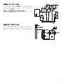
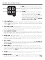
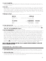
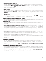
INSTALLATION GUIDE
•
OWNER’S GUIDE
PRO-SERIES ALARM SYSTEM
MODEL 5002PRO
CONTENTS
System Features ......................................2
System Components ....................................2
Required Tools .......................................2
Technical Assistance .................................2
Before You Begin .....................................3
Precautions ..........................................3
Testing Your Wires ...................................3
Making Wiring Connections ..........................3-5
Locating & Making Connections ......................5-7
Installation Instruction ...........................7-9
Wiring Diagram ......................................10
Operating Instructions ...........................11-12
Programming Instructions .........................12-13
Technical Assistance
All tech personnel are expertly qualified to answer any technical questions.
Technicians are available Monday through Friday from 9:00 a.m. until 8:00 p.m. and Saturday 10:00 a.m. until 4:00 p.m.
Address
288 Canton Avenue • Wintersville, Ohio 43953
Telephone
Phone: 740-264-4710 • 800-878-8007 • Fax: 740-264-7306
Downloaded from: http://www.guardianalarms.net
SYSTEM FEATURES
Keyless Entry
Allows you to remotely lock an unlock your power door locks even if the engine is running
or the alarm is in valet mode.
Active Arming
System arms only when transmitter button is pressed.
Passive Arming
Automatically arms the system 1 minute after the last door is closed. (remotely programmable)
Passive Arming
with Door Locks
Arms system and locks doors automatically. Lowers car insurance in most states.
(remotely programmable)
Pre-Arming Chirps to
Passive Arming
Warns you that your alarm will arm itself in 30 seconds. (Patented)
Valet
Prevents arming when being serviced, valet parked or washed. While in valet mode, you still
remotely lock and unlock the power door locks and access instant panic from your transmitter.
(remotely programmable)
Remote Car Finder
Locates your vehicle by chirping the siren and flashing the vehicles lights when activated
by the transmitter, (i.e. crowded parking lots)
6 Tone 126db Siren
Attracts more public attention by changing its tone every 6 seconds.
2 Long Range Four Button
Remote Transmitters
Hand-held, easy to use remotes that operates the system from a safe distance.
Current Sensing
Detects any voltage reduction in the vehicle caused by an interior dome light, hood or
trunk light coming on. (remotely programmable)
Distracted Entry
In passive arming mode, if you disarm the system and get distracted from entering the
vehicle, the system automatically rearms itself in one minute, if the doors have been opened
or not.
Progressive Warning
Sounds pre-alarm warning chirps when a shock sensor or door switch trigger. These chirps
remind you to disarm the system before the 126db siren goes to full volume.
Silent Arming
The system will perform all its functions except no chirping sound when arming and disarming
the system.
Locking and Unlocking with
the Ignition Switch
The doors will lock when the ignition is turned on and unlock when the ignition is turned
off. (remotely programmable)
Trunk Release
Remotely opens your trunk with a single push of a button.
Dome Light
Never walk up to a dark vehicle again. When disarming the vehicle, the dome light will
come on and stay on for 30 seconds, or until you activates the ignition switch.
On Board Parking
Light Relay
Built in relay provides a positive (+) parking light output. No external relay needed.
Code Learning
Allows your alarm to learn new remotes, should you want to add remotes, or if remotes are
lost.
Automatic
Annoyance Override
If the same zone is violated 3 times while armed, that zone will turn off until the alarm
is disarmed and rearmed.
Starter Disable (Relay and
included)
Prevents a thief from starting your vehicle when your system is armed, even if he or she
has your keys.
Ignition Detection
Adds protection by sounding the siren and flashing the lights if the ignition wire is hotwired or turned on when the system is armed, even if the current sensor or door switch
wires have been cut.
Instant Personal
Provides instant panic protection by Panic Protection sounding the siren and flashing lights
while inside or outside the vehicle, even if the engine is running.
Plug In 7 Function LED
Status Indicator
A visual theft deterrent flashes when the system is armed. Lets you know which zone has
been violated, and provides a visual reference to indicate if it is armed or in valet mode.
1
Special Situations
Allow you to remotely lower the sensitivity of your shock sensor for special situations
(i.e. when parking in or near construction zones, heavy rain, trucks, etc.) (remotely
programmable)
Computer Controlled Fan
Sensor Override
No additional wiring needed. This model distinguishes between an electric fan turning on
and a light bulb.
E Squares Memory Back Up
The system memorizes its programmed features if power is lost.
Limited Lifetime Warranty
Guarantees Lifelong protection.
SYSTEM COMPONENTS
Your system includes:
1-Installation & Operation Guide
1-Main Control Module
2-Four Button Remote Transmitter with Slide Protector
1-126db Six Tone Siren
1-Wireless Harness
1-Momentary Switch
1-Extended Range Antenna
1-Anti-carjacking Switch
1-LED Status Indicator with Bracket
1-Warranty
1-Warning Sticker for Under the Hood
2-Bulldog Window Decals
REQUIRED TOOLS
You will need a computer-friendly test light, electrical tape, extra 16 awg wire and wire strippers or
cutters.
TECHNICAL ASSISTANCE
Should you need help. First check our website at www.bulldogsecurity.com/wires.htm or call our toll-free
Tech Support Hotline Monday through Friday 9AM-8PM and Saturday 10AM-4PM EST at 800-878-8007.
You must give the following information:
Name
•Telephone Number with Area Code (Fax number if applicable)
•Year, Make, and Model of the vehicle
•The model number of the system you are installing
•The type of assistance you are requesting
If you give the above information you will be called back as soon as possible, usually within 10 minutes.
BEFORE YOU BEGIN
Congratulations, you have purchased one of the most advanced alarm systems ever made. Your new remote
starter is a technological breakthrough utilizing the most advanced, state of the art technology and
components. It is computer controlled and manufactured in the U.S.A. The dependability and variety of
features make Bulldog Security the leader in the industry. Enjoy your new remote starter for years to
come!
This remote system is designed to start your vehicle by sending a command signal from the remote transmitter
2
or by programming automatic temperature or timed start. It is required that your installation is done in
a well-ventilated area. It is the responsibility of the owner to ensure that the remote system is not
used to start the vehicle in an undesired location.
It is recommended that a carbon monoxide detector be installed in the living area near a location where
the vehicle may be garaged.
Since there are many different makes and models of vehicles, look at the wiring chart on or our website,
www.bulldogsecurity.com/wires.htm.
Read this manual thoroughly before starting the installation. You must also decide if any options are
desired such as trunk release and dome light supervision. An optional relay will be needed for these
options. Please do not skip any steps.
TACH/TACHLESS OPERATION
In most cases the decision to go with tachless mode will save time during the installation. If your vehicle
is hard-starting then you should use tach mode.
MAKE SURE YOU PLACE THE WARNING STICKER UNDER THE HOOD.
PRECAUTIONS
This system is designed for vehicles with power door locks only.
This system will add remote keyless entry features to any vehicle with power door locks. This will also
work as a replacement system for the factory installed keyless entry system.
DO NOT use mechanical wiring connections, such as crimp or snap together taps. Follow instructions
on pages 2-3.
DO NOT disconnect the battery if the vehicle has an anti-theft-coded radio or is equipped with an airbag.
Doing so may cause a warning light to be displayed and may require a trip to the dealer to be corrected.
DO NOT leave the interior or exterior lights on for an extended period of time as it may cause battery
drain.
DO NOT mount the control module until all connections have been made and tested. Using wire ties or
double sided tape, MOUNT THE MODULE UNDER THE DASH.
TESTING YOUR WIRES
When testing for a positive or negative voltage, you must use a computer friendly test light (logic probe)
or a volt/ohm meter. Make sure to probe and test each wire before making your connections.
MAKING WIRING CONNECTIONS
1. Strip back two inches of insulation on the wire from the keyless entry.
Two Inches of Bare Wire
2. Strip back one inch of insulation on the wire you need to connect to.
One Inch of Bare Wire
3. Separate the vehicle wire as shown. Make the separation large enough to fit the other wire
through.
3
4. Insert the wire from the unit through the hole as shown.
5. Wrap the wire around one side then the other and finally around itself as shown.
1
2
3
6. Use electrical tape to wrap. Be sure to cover the wire about two inches on either side of the
connection. First pull the wire that you have just connected along side the wire you connected
to, tape and wire tie them together. Use this method for all connections.
Wire Tie
Electrical Tape
CAUTION: All wires must be wrapped and taped.
MAKING END TO END CONNECTIONS
FOLLOW THESE INSTRUCTIONS
1. When tying two separate wires together at their ends, strip back 1” of insulation on both
wires and separate the strands of wire as shown below.
2. Twist upper wires together, twist lower wires together as shown.
3. Lay upper twisted pair of wires over right wire as shown. Bring lower twisted pair of wires
up to meet the left wire as shown.
4
4. Use electrical tape to wrap, be sure to cover about 2 inches on either side of connection.
Secure with wire ties as shown.
Electrical Tape
Wire Tie
Wire Tie
Use this method ONLY when connecting two separate wires end to end.
LOCATING & MAKING CONNECTIONS
Please see the wiring chart on our website, www.bulldogsecurity.com.
MOUNTING AND CONNECTING THE SIREN
Select a location under the vehicle's hood for the siren. For best results, the location should meet the
following conditions.
•The mounting location should be solid and have no moving parts nearby.
•For the loudest sound, the siren should point down.
•The siren should not point straight up as moisture could collect in the siren horn and damage the system.
•To prevent water damage, the system should not be mounted in a wheel well, directly behind the
radiator grill, or close to the ground.
Once you select a location, follow these steps to mount the siren:
1.Using the siren base as a template, mark the three mounting holes.
2.Drill an 1/8" hole at each mounting hole location, taking care not to damage anything behind the
mounting surface.
3.Secure the siren to the mounting location with two of the mounting screws.
4.Connect the siren's black wire to the third mounting screw, suing the spade connector.
5.Connect the siren's red wire to the module's grey wire.
FINDING CONSTANT AND IGNITION POWER
Your system operates from 12 volts. In addition, the system needs a source of power that is only on when
the ignition is on (usually referred to as ignition power).
1.Locate the wires going to your ignition switch.
2.There is usually a large gauge wire going to your ignition switch. Probe the wire. Confirm that the
light comes on or the meter indicates 12 volts.
3.Mark this wire with its function (Constant Power).
4.Turn the ignition ON. Probe for a wire that has 12 volts only when the ignition is on. Confirm this by
turning the ignition on and off while probing each wire.
5.Mark this wire (Ignition Power).
CONNECTING POWER AND GROUND
1.Connect the red wire from the harness to a constant 12 volt supply or at the positive post of the battery.
2.Connect the black wire from the harness to a clean chassis ground using the spade terminal. TEST: Press
transmitter button #1 and the siren should chirp once. Wait 5 seconds, then press transmitter button
#1 again, and the siren should chirp twice.
CONNECTING IGNITION POWER
Connect the red/black wire from the harness to the wire marked "Ignition Power". TEST: Turn the ignition
switch to the ON or accessory position and then press transmitter button #1, the system should not arm.
If it does, you are not connected to the power wire.
CONNECTING THE STARTER DISABLE
Optional in 5002 Models, Use Part #30-ARB(Model 757) and Pro 1000 Harness (Model 769)
Locate the cranking wire at the base of the steering column. When testing, cranking wire will show 12
volt DC only when the key is in the cranking position. Once located, cur the wire in two. Try to crank
the engine, it should not crank. Next, mark both ends of the cranking wire. The wire running back into
the steering column mark key side, and the wire running toward the engine, mark engine side.
1.Connect the control module orange wire negative (-) out when armed to the optional starter disable relay
(-) negative input.
2.To connect the Key Side and the Starter Side of the cranking wire to the optional relay for starter
disable.
3.Use a wire tire to secure the starter disable relay to a non-moving part under the dash. TEST: Press
transmitter button #1 to arm the system and then try to start the engine, it should not start. Press
5
button #1 again to disarm the system. This time the engine should start. Make sure all your connections
are electrically sound. NOTE: A 1N4001 diode must be used when connecting more than one device to the
orange wire as shown.
STARTER DISABLE RELAY AND HARNESS
87
Optional in 5002 Models use Part #30-ARB (Model 757) and Pro 1000 harness (Model 769)
1.Connect the control module orange wire negative (-) out when
86 87A 85
armed to the optional starter disable relay (-) negative input.
ORANGE
2.To connect Key Side and Starter Side of cranking wire to the optional
relay for starter disable,
3.Use a wire tie to secure the starter disable relay to a non-moving
30
part under the dash. TEST: Press transmitter button #1 to arm the
system and then try to start the engine, it should not start. Press
CRANKING
button #1 again to disarm the system. This time the engine should
TO STARTER
IGNITION
WIRE
start. Make sure all your connections are electrically sound.
NOTE: A 1N4001 diode must be used when connecting more than one device to the orange wire as shown.
INSTALLING THE FLASHING LED STATUS INDICATOR
The LED indicator installs inside your vehicle and should be installed as
high as possible and in view from all windows. Drill a 1/4" mounting hole
in the dash panel or use the supplied mounting bracket to hold the LED
status indicator in place.
CONNECTING THE LED STATUS INDICATOR
1.Insert the blue plug of the LED status indicator into the
right side of the main header. TEST: Press transmitter
button #1, the LED should flash.
WHITE PLUG
ON THE LEFT
OF MODULE
BLUE PLUG
ON THE RIGHT
OF MODULE
LED
INDICATOR
OVERRIDE
SWITCH
GROUND
FINDING THE PARKING LIGHT WIRE
To have the parking lights flash during a violation or when you use the car finder, you must connect your
alarm system to the vehicle's parking lights.
1.Locate the wire harness going from the back of your vehicle's light control. If the control is on your
vehicle's steering column, the harness probably joins several other wiring harnesses.
2.Use the vehicle's wiring color code to find the parking lights wire, or simply connect this wire to
the marker light wire ususlly found under the hood.
3.Turn on the parking lights. Touch one lead from a 12 volt test light or volt meter should indicate 12
volts only when the lights are on.
4.After you locate the light wire, use a piece of masking tape to mark it with its function (lights).
CONNECTING THE PARKING LIGHT WIRE
1.Connect the brown wire from the wiring harness to the wire marked "lights". TEST: Press transmitter
button #1, the parking lights should flash once, wait 5 seconds, then press the transmitter button #1
again and the parking lights should flash twice, and then stay on for 30 seconds.
DETERMINING YOUR VEHICLE'S DOOR PIN SWITCH TYPE
NOTE: For your alarm system's passive arming and in model 7002 the anti-carjacking feature to work, you
must connect the alarm to the door pin switch.
1.On some vehicles this wire might also be called a door trigger and is usually behind the driver's kick
panel or behind the driver's door panel. Some vehicles have logic controlled dome and courtesy lights
that turn on differently depending on which vehicle door is opened. Be sure to locate a wire that is
triggered from all your vehicle's doors.
2.Touch your meter or test light's positive lead to a point on the fuse block that has constant 12 volts.
Use the other lead to probe the control wire. Then open the door. If the test light turns on or the
meter indicates 12 volts, your vehicle has a negative (-) switch door pin.
3.Connect your meter or test light's negative lead to a good solid chassis ground. Use the positive
lead or other lead probe to the control wire. Then open the door. If the test light turns on or
the volt meter indicates 12 volts, your vehicle has a positive (+) switch door pin.
4.Use masking tape to mark the wire with its function (door) and switching type, positive (+) or
negative (-) switch.
CONNECTING THE DOOR PIN SWITCH
If you marked the door switch "wire door negative (-) switch", connect the main wiring harness's
black wire with yellow stripe to the door switch wire. If you marked the door switch "wire door
positive (+) switch", connect the main wiring harness's black wire with blue stripe to the door switch
wire.
NOTE: The door inputs activate 20 seconds after arming. Door switch testing should take place only
after 20 seconds have elapsed after arming. NOTE: Some vehicles such as HONDA have door switch isolation
diodes on each door. These vehicles must be wired at the wire that triggers the dome light circuit
after the diodes. If the door switch wires are difficult to reach, connect the input wire to the
dome light itself.
6
MOUNTING AND CONNECTING THE OVERRIDE SWITCH
Select a location for the override switch. You should be able to reach the switch when sitting in
the driver's seat, but the switch should be hard to find. A typical mounting location is under the
dash. The mounting surface should be less than 1/8" thick.
1.Drill a 5/16" hole in the mounting surface, taking care not to damage anything behind the surface.
2.Remove the switch's top nut and lock washer.
3.Push the switch into the hole from the back of the mounting surface. Then secure it with the lock
washer and not.
4.Connect the ground wire to a metal vehicle body part using an existing screw.
5.Override Switch - Plug override switch into the left side of the main header (this switch is the
same used with anti-carjacking) TEST: Violate any zone on the alarm causing the siren to sound.
Open the vehicle door, place ignition key to "ON" position, then press the override switch. The
siren should silence and you will now be able to start the engine. NOTE: A door must remain open
during this procedure.
MOUNTING AND CONNECTING THE ANTI-CARJACKING SWITCH
Only found on 7002 models
Select a location for the anti-carjacking switch. You should be able to reach the switch when sitting
in the driver's seat, but the switch should be hard to find. A typical mounting location is under
the dash, the mounting surface should be less than 1/8" thick.
1.Drill a 1/4" hole in the mounting surface, taking care not to damage anything behind the surface.
2.Remove the switch's top nut and lock washer.
3.Push the switch into the hole from the back of the mounting surface. Align the switch so ON is
away from the driver. Then secure it with the lock washer andnut.
4.Connect the ground with to a metal vehicle body part using an existing screw. TEST: Close all the
doors, flip the toggle switch to the ON or forward position and start the vehicle. Open and close
a door and wait one minute, the siren will sound. When the siren sounds, turn off the engine and
then try to restart it. The engine should not start. To return the system to normal operation,
turn off the ignition switch, flip the toggle switch to OFF or to the rear and press transmitter
button #1. The siren should stop and you will not be able to start the engine.
CONNECTING ADDITIONAL SENSORS
Follow the instructions that come with the sensor to mount and power it. The system requires a negative
(-) output on the accessory for activation of the alarm.
If the sensor has a single alarm output, connect it to either the main wiring harness's yellow wire
to have the sensor trigger the alarm or to the harness's green wire to have the sensor trigger only
warning chirps.
If the sensor has both warning and alert triggers, connect the warning trigger to the harness's green
wire and the alert trigger to the harness's yellow wire CAUTION: When adding more than one shock
sensor or perimeter sensor on the same input trip, you must add a 1 amp diode to the output of each
sensor.
INSTALLATION INSTRUCTIONS
NEGATIVE OUTPUTS - See wiring schematic
1.Negative output #2 - the white/red wire is used to operate
a ower trunk release power sun roof, window roll-up module,
etc. This negative output will pulse for one half second,
or for as long as transmitter button #2 is depressed. NOTE:
A 30 amp relay must be used since this negative output is
only rated for 200mA (1/5 amp). Since most power trunk
releases are positive controlled and draw 5 to 6 amps, this
relay handles the load and also can convert the release
signal from negative to positive polarity.
2.Negative output #3 - the white/yellow wire is used to operate
the car starter, window roll-up module, etc. The negative
output will pulse for one half second by pressing transmitter
button #3. NOTE: A SPST or SPDT relay must be used if you
want to convert the negative signal to positive or if the
TO FACTORY TRUNK WIRE
WHITE/RED
FROM ALARM
device you're controlling draws more than 200mA. If you're not sure how much
amperage is being drawn, add the relay. This negative output is only rated
for 200mA (1/5 amp). CAUTION: Overloading these outputs is not considered
a warranty related repair.
87a
+12 VOLT FUSED
AT 20 AMPS
7
TO DOME LIGHT CIRCUIT
CONNECTING THE DOME LIGHT SUPERVISION Optional Relay
Connect the violet wire from the control module wiring
harness to the done light wire, normally found in the
driver's kick panel. NOTE: A relay must be used to connect
the dome light supervision function,
(-) VIOLET
FROM ALARM
87a
+12 VOLT
FUSED AT
5 AMPS
(+) OR (-)
DEPENDING ON DOOR TYPE
NOTE: If (+) positive, fuse at 20 amps,
if (-) negative connect to pin 30 to a
chassis ground.
TESTING: Door Locks
There are three basic types:
“Type A” Door Lock Test (Most GMs and some Chryslers)
Probe both of your door lock wires going to the door lock switch usally located in the driver’s
kick panel. Attach the clip end of your test light to a good chassis ground. Using the vehicle’s
door lock controls, activate the lock then the unlock, testing both wires one at a time. If one
of these wires tests (+) positive when lock is pressed and the other tests (+) positive when they
are unlocked, your vehicle has a “Type A” door locking system. Make sure to mark which wire is
lock and unlock. Proceed to Connecting Door Locks, Connecting Door Locks. NOTE: “Type A” and “Type
C” locks will test the same, until you test for ground. Make sure you run both tests before making
your connections.
“Type B” Door Lock Test (Most Imports, some newer Fords)
Probe both of your door lock wires going to the door lock switch usally located in the driver’s
kick panel. Attach the clip end of your test light to +12V. Using the vehicle’s door lock controls,
activate the lock then the unlock testing both wires one at a time. If the test light illuminates
when you probe the lock and the unlock wires your vehicle has a “Type B” door locking system. Make
sure to mark which wire is lock and unlock. Proceed to Connecting Door Locks.
“Type C” Door Lock Test (Most Fords, some Chryslers, GM Trucks)
(Optional part #778 required)
Using your test light probe both the lock and the unlock wires usually located in the driver’s
kick panel. Attach the clip end of your test light to ground probing both wires one at a time while
locking and unlocking the doors with the driver’s side switch (usually the master switch). The
test light should illuminate in both switch positions. Now attach the clip end of your test light
to +12V constant, probe both wires one at a time again. The light should then illuminate again
only in reverse order. This tells you that you have a “Type C” reversing polarity system. Make
sure to mark which wire is lock and unlock. Proceed to Connecting Door Locks.
CONNECTING DOOR LOCKS
(Optional)
CONNECTING “TYPE A LOCKS”
•If your vehicle has a “Type A” door locking system, connect
the BROWN WITH BLACK STRIPE wire from the 18-pin harness
to the door lock wire. Connect the GREEN WITH BLACK STRIPE
wire to the unlock wire. See diagram below.
BROWN/BLACK
LOCK
UNLOCK
GREEN/BLACK
“Type A” - Positive type door locks used on most GM, some
Chrysler vehicles.
CONNECTING “TYPE B LOCKS”
• If your vehicle has a “Type B” door locking system, connect
the GREEN WITH BLACK STRIPE wire from the 18-pin harness
to the door lock wire. Connect the BROWN WITH BLACK STRIPE
wire to the unlock wire. See diagram below.
“Type B” - Negative type door locks used on most imported
vehicles and some newer Fords.
GREEN/BLACK
LOCK
UNLOCK
BROWN/BLACK
8
CONNECTING “TYPE C LOCKS”
•If your vehicle has a “Type C” door locking system,
you will need to purchase optional part #778. Once
you have purchased the relays, follow the diagram on
page 18 for “Type C” door locks.
TYPE C - (Optional Part #778 required)
Reverse polarity door locks. Used on most GM trucks,
Ford and Chrysler vehicles.
YELLOW
BLACK
WHITE
87a
BLUE
RED
BLACK
RED
BLUE
CONNECTING “TYPE D LOCKS”
Adding after-market door lock actuators will also
require adding 2 relays. For simplified installation,
we highly recommend Bulldog’s pre-wired double relay
door lock socket and harness, part #PR01010 (Model
772).
86
87
85
87a
30
86
87
85
87a
30
9
WIRING DIAGRAMS
FIGURE 1
1. Red
(+) 12 volt constant
2. Black
chassis ground
3. Grey
(+) siren output
4. White/Red
button #2 / channel #3 (-) output: trunk
pop, window rollup, etc. 200mA max
5. White/Yellow
button #3 / channel #2 (-) output: remote
start, etc. 200 mA max (see figure 7)
6. Brown/Black
(+) unlock or (-) lock output
7. Green/Black
(+) lock or (-) unlock output
8. Orange
(-) output when armed: starter disable, etc
(see fig. 9)
9. Brown
(+) parking light output
RED
BLACK
10. Open
11. Green
(-) shock sensor input (minor): warn away /
10 second delay after arming
12. Yellow
(+) shock sensor input (major): triggers
alarm / 10 second delay after arming
13. Black/Blue
(+) door pin input / 20 second delay after arming
14. Black/Yellow
(-) door pin input / 20 second delay after arming
15. Violet
(-) output dome light supervision 300mA max (see fig. 6)
16. Red/Black
(+) 12 volt ignition sense input
L
8
7
6
5
4
3
16
15
14
13
12
11
2
1
9
R
10
OPERATING INSTRUCTIONS
BUTTON #1
ARM/DISARM
1
2
BUTTON #2
OPTION #2
BUTTON #3
OPTION #3
3
4
BUTTON #4
PANIC
BULLDOG
1. Arming
Press transmitter button #1 to arm the system. The siren
will chirp 1 time, the lights will flash once, the power
door locks will lock (if installed), and the LED will flash
slowly indicating the alarm is now armed. The engine starter
is also disabled.
2. Disarming
Pressing transmitter button #1 again will disarm the
system. The siren will chirp twice, the lights will
flash twice, and stay illuminated for 30 seconds,
acknowledging that the system is disarmed. NOTE: If you
hear 3 siren chirps and see 3 light flashes when
disarming, the vehicle was violated while you were away.
Check the LED for zone violation (See Operating
instructions #13 Zone Explanation). This is a good time
to check your vehicle for possible damage. Dome light
supervision (optional, must use relay) When disarming,
the dome light will turn on for 30 seconds.
3. Silent Arming/Disarming
Should you desire not to have the siren chirp when arming and disarming, press and hold transmitter
button #1 for 3 seconds. The system will perform all its usual arming/disarming functions, except there
will be no arming and disarming chirps. If the alarm is triggered, the siren will provide its normally
loud sound. NOTE: If the lights flash 3 times after disarming, the vehicle has been violated as described
in Operating Instructions #2.
4. Passive Automatic Arming Factory setting is off
To activate passive arming, disarm the system, then hold down button #3 for 10 seconds. The system
sill chirp once. Press button #3 again within 2 seconds. The system will chirp once to indicate the
system is now set to passive arming. To deactivate passive arming, repeat the above steps. You will
hear 2 chirps indicating passive arming is turned off.
5. Passive Arming With Door Locking Factory setting is off
To activate passive arming with door locking; disarm the system, then press and hold button #3 for 10
seconds. The system will chirp 1 time again. To deactivate passive arming with door locking; disarm
the system, then press and hold button #3 for 10 seconds. The system will chirp 1 time. Press button
#3 within 2 seconds and the system will now chirp twice.
6. High Theft Areas • Not available on 5002
There may be times when you have to park your car in areas that require an extra measure of protection.
This model can be programmed to emit a siren chirp every 30 seconds while the system is armed to warn
away potential thieves. To use this feature, press button #2 within 3 seconds after arming. The siren
will chirp 1 time indicating acceptance of this feature for this arming. The system will return to
normal operation after the system is disarmed.
7. Special Situations
There may be times when you have to reduce the shock sensor's sensitivity by 50% for this arming only,
press button #1 to arm and then again within 2 seconds after arming. To shut the sensor off completely
for this arming only, press button #1 twice within 2 seconds after arming. The next time you arm your
system, the shock sensor will return to the original setting.
8. Remote Car Starter Optional equipment required
A second channel built into this model can be activated while it is in the armed or disarmed mode.
The second channel can be used for remote engine starting, remotely popping the trunk, etc. Press
transmitter button #2 while the system is armed or disarmed, the parking lights will flash once, and
then will activate the installed accessory. As long as transmitter button #2 is pressed, a ground signal
is applied to the accessory. CAUTION: When remotely starting the vehicle while the system is armed,
shock and current sensing will shut off.
9. Car Finder
While the system is armed, press and release button #3. The alarm will chirp 6 times and the parking
lights will flash. This is used to locate your vehicle in a crowded parking lot.
10. Optional Accessories
Trunk Pop, etc., must use relays NOTE: When the alarm is disarmed, press button #4 and the trunk will
open. When the alarm is armed, press and hold button #3 for 2 seconds or until the trunk opens. CAUTION:
When opening the trunk while the system is armed, shock and current sensing will shut off.
11
11. Instant Personal Panic
Press and release transmitter button #4 to sound the instant panic siren. The lights and siren will
activate for 30 seconds and then shut off. To stop the siren before the 30 seconds, press any of the
4 transmitter buttons.
12. Valet Mode
The valet mode prevents the system from arming. To activate valet mode, first disarm the system. Hold
down button #4 for 10 seconds. The system will chirp 1 time. Press button #4 again within 2 seconds.
The system will chirp once. The LED will remain solid red win in valet mode. To deactivate the valet,
repeat the above, however, the system chirps twice when you press button #4 the second time. The LED
turns off. This feature is useful when having your vehicle valet parked, washed or serviced. While in
valet mode keyless entry and instant panic will still work, however the alarm will not arm. Valet mode
may also be programmed while the engine is running.
13. LED Status Indicator
The LED (red light) provides valuable information about the system and is also a theft deterrent.
LED Status
LED Display
Armed......................................Flashing Slow
Disarmed.............................................Off
Passive Arming .........Flashing Fast (arming count down)
Valet ......................................Constantly On
Violated Zone
Triggered Device
Zone 2.............................On Board Shock Sensor
Zone 3..................................External Sensors
Zone 4 ....................................Voltage Sensor
Zone 5 ....................................Door Switches
#
2
3
4
5
of Flashes
Flashes
Flashes
Flashes
Flashes
14. Plug In Override Switch
In the event your remote control is lost, damaged or malfunctions; this switch allows you to disarm
your system. You must first open the door to the vehicle, turn ignition to the "ON" position, then
press the override switch. The siren will silence and you will now be able to start the engine. NOTE:
A door must remain open during this procedure.
15. Anti-Carjacking Protection • Not available on 6002/5002
We strongly recommend you use this feature only in unsafe neighborhoods. To activate the anti-carjacking
system, flip the toggle switch forward to the "ON" position. To turn the anti-carjacking system off,
switch the toggle backward to the "OFF" position. If any door is opened and then shut when the anticarjacking switch is in the "ON" position and the engine is running, the siren will sound and the lights
will begin to flash in one minute. If the engine is shut off it will not restart. If activated, to
turn off the anti-carjacking you must turn the ignition off, flip the toggle backward to the "OFF"
position and then press button #1 on the transmitter. We recommend turning the anti-carjacking off
when in safe areas. The 1 minute time delay allows you to leave the area of danger and later makes
the car undriveable for the carjacker. Unlike a normal violation, the alarm will not reset after 30
seconds. The siren will continue to sound and the lights will continue to flash until the proper
deactivation steps have been performed. To deactivate the anti-carjacking protection, turn the ignition
switch off, flip the toggle backwards or to the "OFF" position, then press transmitter button #1. The
siren will chirp twice, confirming that the anti-carjacking protection is disengaged. You may now start
the engine. NOTE: If you accidentally activate the anti-carjacking protection, you may deactivate it
before or after the siren sounds. (IT MUST BE DONE WITHIN 1 MINUTE OR THE SIREN WILL SOUND.)
CAUTION: DO NOT TURN ON THE DOME LIGHT WHILE THE ANTI-CARJACKING PROTECTION IS ENGAGED. THIS WILL ALSO
ACTIVATE THIS PROTECTION FEATURE.
PROGRAMMING INSTRUCTIONS
1. Activating Current Sensing Factory setting is off
To activate current sensing, disarm the system, and hold button #4 for 10 seconds. The system will chirp once
again. To deactivate current sensing; repeat the above except you will hear 2 chirps after pressing button #3.
2. Activating the Shock Sensor Factory setting is on
To deactivate the shock sensor, disarm the system, then press and hold button #4 for 10 seconds. The system will
chirp once, Press button #2 within 2 seconds. The system will chirp twice. To activate the shock sensor; repeat
the above except you will hear 1 chirp after pressing button #2.
12
3. Setting the Shock Sensor's Sensitivity
Disarm the system, press and hold button #4 for 10 seconds. The system will chirp once. Within 2 seconds, press
button #1. The system will chip twice. Within 2 seconds, strike your vehicle with as much force as you want the
alarm to respond to. Strike the windshield for best results. The system will chirp twice immediately after being
struck to confirm acceptance. NOTE: If you do not strike your vehicle within 2 seconds, the alarm is set to its
maximum sensitivity. A first shock will cause the system to give a warning chirp, an a second shock within 30
seconds will set off the system.
4. Special Situations
Sometimes when you park your car in heavy rain, near a construction zone, near trucks, etc., you may wish to lower
your shock sensor's sensitivity for this arming only. To reduce the shock sensor's sensitivity by 50%, press button
#1 again within 2 seconds after arming. To shut the sensor off completely, press button #1 twice within 2 seconds
after arming. You will notice a decrease in the tone of the system when reducing the sensitivity. The next time
the system is armed, it will return to the original setting.
5. High Theft Areas
To activate the high theft area setting; press and release button #2 within 3 seconds after arming. The siren
will chirp once indicating acceptance of this feature. The system will now emit a chirp every 30 seconds for this
arming. The system will return to normal operations after the system is disarmed.
6a. Activating Passive or Automatic Arming without Door Locking Factory setting is off
To activate passive arming; disarm the system, then hold down button #3 for 10 seconds. The system will chirp
once. Press button #3 again within 2 seconds. The system again will chirp once. To deactivate passive arming; repeat
the above, except you will hear 2 chirps after pressing button #3.
6b.Passive Shock Lock
If the unit is programmed for passive arming without locking the doors, the unit will lock the doors upon a shock
sensor violation. One minute after violation has stopped, the doors will automatically unlock, but the system sill
remain armed.
7. Activating Passive or Automatic Arming with Door Locking Factory setting is off
To activate passive arming with door locking; disarm the system,then press and hold button #3 for 10 seconds. The
system will chirp once. Press button #3 within 2 seconds. The system will chirp again once. Press button #3 again
within 2 seconds to activate door locking. The system will chirp again once. To deactivate passive arming with door
locking; disarm the system, then press and hold button #3 for 10 seconds. The system will chirp once. Press button
#3 within 2 seconds. The system will chirp twice.
8. Activating Valet Factory setting is on
To activate valet; disarm the system. Press and hold button #4 for 10 seconds. The system will chirp once. Press
button #4 within 2 seconds. The system will chirp once. To deactivate valet, repeat above except you will hear 2
chirps after pressing button #4 the second time.
9. Activating Locking and Unlocking with the Ignition System Factory setting is off
To activate locking and unlocking with the ignition; disarm the system, then press and hold button #3 for 10 seconds.
The system will chirp once. Press button #2 within 2 seconds. The system will chirp again once. To deactivate locking
and unlocking with the ignition system; repeat the above process except you will hear 2 chirps after pressing
button #2.
10. Changing the Door Lock Pulse Factory setting is 0.6
Door lock pulse duration is 0.6 or 3.5, the 3.5 seconds is for vacuum operated door lock systems as found in Mercedes
Benz, Audi and Volkswagon. To program the 3.5 second timing cycle; disarm the system, the press button #3 for 10
seconds. The system will chirp once, then press button #1 within 2 seconds. The system will chirp once again to
confirm the timing change. To change the door lock pulse back to 0.6 seconds, repeat the above except you will
hear 2 chirps after pressing button #1. CAUTION: Be careful not to use the 3.5 setting for actuator door locks as
it will damage components.
11. Programming and Additional or New Remote Transmitter
If you already have a remote transmitter and it is working, simply press and hold button #1 for 10 seconds, the
system sill chirp once. Immediately press the first button on the new remote. The parking lights will flash twice,
the system has now learned the new remote. If you do not have the original remote transmitter that came with your
system, disconnect the system from the battery for at least 30 seconds, reconnect and press the first button on
your new transmitter. Your system will now operate with your new remote transmitter. NOTE: If you have a 9 volt
battery backup installed, it must be removed before the power is disconnected.
13