1
Operators Manual
Installation, Operation & Service
Electric T1 Skillets
MODELS:
SEL-30-T1
SEL-40-T1
1333 East 179th St., Cleveland, Ohio, U.S.A. 44110
Enodis
Phone: (216) 481-4900 Fax: (216) 481-3782
Visit our web site at www.clevelandrange.com
SE95051
FOR THE USER
WARNING:
!
Improper installation, adjustment, alteration, service or maintenance
can cause property damage, injury or death.
Read the Installation, Operating & Service instructions thoroughly
before installing or servicing this equipment.
IMPORTANT
THE INSTALLATION AND CONNECTION MUST COMPLY WITH THE LOCAL AND
NATIONAL ELECTRICAL CODES.
ENSURE ELECTRICAL SUPPLY CONFORMS WITH ELECTRICAL CHARACTERISTICS
SHOWN ON THE RATING LABEL
ALL SERVICE MUST BE PERFORMED BY A QUALIFIED CLEVELAND RANGE TECHNICIAN.
RETAIN THIS MANUAL FOR YOUR REFERENCE.
TABLE OF CONTENTS
Installation
General. . . . . . . . . . . . . . . . . . . . . . . . . . . . . . . . . . . . . . . . . . . . . . . 1
Inspection / Unpacking . . . . . . . . . . . . . . . . . . . . . . . . . . . . . . . . . . 1
Shipping Damage Instructions. . . . . . . . . . . . . . . . . . . . . . . . . . . . . 1
Installation . . . . . . . . . . . . . . . . . . . . . . . . . . . . . . . . . . . . . . . . . . . . 1
Wire Connection . . . . . . . . . . . . . . . . . . . . . . . . . . . . . . . . . . . . . . . . 2
Water Connection . . . . . . . . . . . . . . . . . . . . . . . . . . . . . . . . . . . . . . . 2
Installation Checks. . . . . . . . . . . . . . . . . . . . . . . . . . . . . . . . . . . . . . 2
Cleaning . . . . . . . . . . . . . . . . . . . . . . . . . . . . . . . . . . . . . . . . . . . . . . 2
Specification Drawing . . . . . . . . . . . . . . . . . . . . . . . . . . . . . . . . . . . 3
Operating Instructions
General Parts Drawing . . . . . . . . . . . . . . . . . . . . . . . . . . . . . . . . . . 4
Operating the Unit . . . . . . . . . . . . . . . . . . . . . . . . . . . . . . . . . . . . . . 5
Operating Suggestions . . . . . . . . . . . . . . . . . . . . . . . . . . . . . . . . . . . 5
Cleaning Instructions
Care & Cleaning . . . . . . . . . . . . . . . . . . . . . . . . . . . . . . . . . . . . . . . 6
Service Parts
Warranty . . . . . . . . . . . . . . . . . . . . . . . . . . . . . . . . . . . . . . . . . . . . . . 7
Faucet Assembly. . . . . . . . . . . . . . . . . . . . . . . . . . . . . . . . . . . . . . . . 7
Pan Mount Assembly . . . . . . . . . . . . . . . . . . . . . . . . . . . . . . . . . . . . 8
Tilt Components . . . . . . . . . . . . . . . . . . . . . . . . . . . . . . . . . . . . . 9-10
Control Box Assembly . . . . . . . . . . . . . . . . . . . . . . . . . . . . . . . . . . 11
Component Plate Assemblies . . . . . . . . . . . . . . . . . . . . . . . . . . . . . 12
Frame / Lid Assembly . . . . . . . . . . . . . . . . . . . . . . . . . . . . . . . . . . 13
2" Tangent Draw-Off Valve . . . . . . . . . . . . . . . . . . . . . . . . . . . . . . 14
Maintenance
Hinge Adjustment Instruction . . . . . . . . . . . . . . . . . . . . . . . . . . . . 15
Lubrication Procedure . . . . . . . . . . . . . . . . . . . . . . . . . . . . . . . . . . 15
Sequence of Operations . . . . . . . . . . . . . . . . . . . . . . . . . . . . . . . . . 16
Power Tilt Manual Override . . . . . . . . . . . . . . . . . . . . . . . . . . . . . 16
Spare Parts Lists . . . . . . . . . . . . . . . . . . . . . . . . . . . . . . . . . . . . . . 17
Wiring Diagram . . . . . . . . . . . . . . . . . . . . . . . . . . . . . . . . . . . . . . . 18
Symbol Legend . . . . . . . . . . . . . . . . . . . . . . . . . . . . . . . . . . . . . 19-20
INSTALLATION
GENERAL
SHIPPING DAMAGE
INSTRUCTIONS
Installation of the unit must be accomplished by
qualified electrical installation personnel working
to all applicable local and national codes.
Improper installation of product could cause injury
or damage.
If shipping damage to the unit is discovered or
suspected, observe the following guidelines in
preparing a shipping damage claim.
1. Write down a description of the damage or the
reason for suspecting damage as soon as it is
discovered. This will help in filling out the claim
forms later.
This equipment is built to comply with applicable
standards for manufacturers. Included among
those approval agencies are: UL, NSF, ASME/Ntl.
Bd., CSA, CGA, ETL, and others. Many local
codes exist, and it is the responsibility of the
owner/installer to comply with these codes.
2. As soon as damage is discovered or suspected,
notify the carrier that delivered the shipment.
3. Arrange for the carrier's representative to
examine the damage.
Note: Maximum voltage for LVD (low volt directive for Europe) to be 440 volts for CE marked
appliances.
4. Fill out all carrier claims forms and have the
examining carrier sign and date each form.
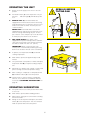
INSPECTION / UNPACKING
INSTALLATION
Note: The electrical rating label is located on the
right console. Serial number, voltage, phase,
amperage and wattage are stated on this label.
Note: For clearance requirements, suggested
drain location and assembly details refer to
"SPECIFICATION DRAWING" on page #3.
1. Before unpacking visually inspect the unit for
evidence of damage during shipping.
1. Position the unit in it's permanent location, and
level the unit by turning the adjustable feet.
2. If damage is noticed, do not unpack the unit,
follow "SHIPPING DAMAGE INSTRUCTIONS"
shown below.
2. Once positioned
4 7/8" (124mm)
and leveled, per120
120
manently secure
the unit's rear
7/16"Ø, 3 HOLES
flanged feet to
ON 3 1/8" (80mm) B.C.D.
the floor using
FLANGED FOOT DETAIL
5/16" lag bolts
(REAR LEGS ONLY
and floor
anchors (supplied by the installer). Three bolts are required
to secure each of the flanged feet.
3. Carefully remove unit from shipping carton.
Remove any packing material from unit. After
carefully unpacking check for "concealed"
damage. If damage is noticed, follow
"SHIPPING DAMAGE INSTRUCTIONS" shown
below.
)
4. Check the electrical rating label to ensure that
the unit is the correct voltage, phase, amperage and wattage are stated on this label.
3. Seal joints of flanged feet with a silicone
sealant.
5. A protective material has been applied to the
stainless steel panels. This material must be
removed immediately after installation, as heat
will melt the material and make it more difficult
to remove.
1
WIRE CONNECTION
INSTALLATION CHECKS
Note: Ensure main power is turned off before
connecting wires.
Although the unit has been thoroughly tested before
leaving the factory, the installer is responsible for ensuring the proper operation of unit once installed.
General Information
Install in accordance with local codes and/or the
National Electric Code ANSI/NFPA No. 70-1990
(USA) or the Canadian Electric Code CSA
Standard C22.1 (Canada). A separate fused disconnect switch must be supplied and installed.
The unit must be electrically grounded by the
installer.
1. Supply power to the unit by placing the fused disconnect switch to the "ON" position.
The electrical supply must match the power
requirements specified on the unit's rating label.
The copper wiring must be adequate to carry the
required current at the rated voltage. Wire must be
suitable for at least 194°F (90°C). Refer to "SPECIFICATION DRAWING" on page #3 for all electrical
specifications. Cleveland strongly recommends
the use of liquid tight fittings.
7. Turn Temperature Dial 300°F (150°C). Unit will continue to heat, Heat Indicator Light (yellow) will
remain ON until temperature is reached. Then the
heat indicator light will cycle off indicating the heating system has shut OFF. The heat indicator light will
continue to cycle ON and OFF as the heating system cycles ON and OFF maintaining the desired
temperature.
2. Turn Temperature Dial to 150°F (66°C).
3. Toggle Power Switch to the "ON" position.
4. Heat Indicator Light (yellow) should be ON and unit
heating. When temperature is reached, Yellow
Indicator Light will switch OFF.
3. Toggle Power Switch to the "OFF" position.
Connection
NOTE: Wiring diagram is located under the top
cover of the unit's right console.
CLEANING
ENSURE THE ELECTRICAL SUPPLY MATCHES
THE UNIT'S REQUIREMENTS AS STATED ON
THE ELECTRICAL RATING LABEL.
After installation the unit must be thoroughly
cleaned and sanitized prior to cooking. See complete cleaning instructions in this manual (page
#6).
The supply lines will enter through the bottom of
the right console and are connected to the terminal block.
WATER CONNECTION
(OPTIONAL)
A 1/2" NPT cold water line and/or a 1/2" NPT hot water
line are required if unit is equipped with a single or double pantry faucet.
2
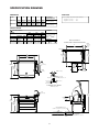
SPECIFICATION DRAWING
DIMENSIONS
MODEL
SEL-30-T1
SEL-40-T1
CAPACITIES
A
B
C
D
F
G
39 1/8"
24 1/2"
31 3/4"
12"
18 1/4"
5 3/4"
(994mm)
(623mm)
(807mm)
(305mm)
(464mm)
(146mm)
51 1/8"
36 1/2"
43 3/4"
18"
24 1/4"
5 3/4"
(1299mm)
(928mm)
(1112mm)
(458mm)
(616mm)
(146mm)
APPROXIMATE
SHIPPING WEIGHTS
In 4 oz. servings. Other sizes may be calculated.
30 gallons / 115 Liters.............960
40 gallons / 150 Liters...........1280
SEL-30-T1
390 LBS. (178 KG.)
SEL-40-T1
410 LBS. (187 KG)
SPECIFICATIONS
CLEARANCE
ELECTRICAL SUPPLY
MODEL
SEL-30-T1
SEL-40-T1
208V
240V
480V
AMPS
AMPS
AMPS
WATTAGE
KW
3ph
1ph
3ph
1ph
3ph
Standard
12
33.3
57.7
28.9
50
14.5
High
16
44.4
77
38.6
66.7
19.3
Standard
18
50
86.5
43.4
75
21.7
High
24
66.7
NA
57.8
NA
28.9
RIGHT:
3" (77mm) (manual tilt)
0" (power tilt)
LEFT: 0",
REAR: 0"
APPROVALS
UL
LEG LOCATION &
SUGGESTED FLOOR DRAIN DETAIL
CSA
5 1/4"
(134mm)
C
(FAUCET
OPEN)
3 7/8" (99mm)
30"
(762mm)
25 15/16"
(659mm)
A
B
(PAN SURFACE)
H C
41"
1042mm
DPK
(OPTION)
FLOOR
DRAIN
GRATE
28 3/4"
731mm
12" x 20"
(305mm x
508mm)
(PAN
SURFACE)
2 1/4"
(57mm)
D
4 7/8" (124mm)
120
5"
(127mm)
(MANUAL
TILT HANDLE)
120
7/16"Ø, 3 HOLES
ON 3 1/8" (80mm) B.C.D.
2" (51mm)
1" (26mm)
9/16" (15mm)
(MAXIMUM
ADJUSTMENT
FLANGED FOOT DETAIL
(REAR LEGS ONLY)
75
DPK
(OPTION)
71"
1804mm
9 1/2" (241mm)
(PAN DEPTH)
H C
39"
991mm
35"
889mm
(RIM
HEIGHT)
RECOMMENDED FLOOR
SLOPE 1" (26mm) IN 4' (1220mm)
4" (102mm) MINIMUM
6" (153mm) RECOMMENDED
FLOOR DRAIN
PIPE DRAIN RECOMMENDED
MINIMUM VALVE SIZE PLUS 1" (26mm)
3
OPERATING INSTRUCTIONS
KE95604-1
3
1
8
2
4
5
General Parts Drawing
ITEM #
DESCRIPTION
FUNCTION
1.
Power Switch
Lower position - power to the unit is OFF.
Upper position - power to the unit is ON.
2.
Temperature Dial
Regulates the surface temperature of the pan.
3.
Heat Indicator Light
Turns ON when heating system is on and OFF when system is off.
4.
Hand Tilt Wheel
Used for tilting the pan up or down. Some units have an optional
Power Tilt with the tilt switch located in the same position.
5.
Manual Tilt Override
Used on units with optional Power Tilt for tilting the pan up or down
in case of power or mechanical failure.
6.
Tangent Draw-Off Valve
(not shown)
Option - allows you to discharge product from the pan through
the valve.
7.
Faucet
(not shown)
Option - Hot and/or cold faucet mounts to skillet for
convenient filling of the pan.
8.
Power Indicator Light (Red)
Indicates power is on.
4
OPERATING THE UNIT
1.
Ensure electrical supply to the unit is in the ON
position.
2.
Turn Power Switch (1) to the ON position. The yellow Heat
Indicator Light (3) will indicate power
is on.
3.
MANUAL TILT (4): Cleveland skillets are
equipped with a manual tilt mechanism for raising
and lowering the pan. To raise pan, raise the cover
and turn the crank clockwise. To lower pan, turn
counterclockwise.
!
OPEN LID BEFORE
TILTING PAN
1
2
POWER TILT: Cleveland skillets can also be
equipped with an optional electric power tilt mechanism for raising and lowering the pan. To raise
pan, raise the cover and press up on the tilt switch.
To lower pan, press down on the tilt switch.
4.
FOR YOUR SAFETY: This skillet is also
equipped with a power interrupter which automatically shuts of the power to the elements whenever
the skillet is raised more than 1/2" (13mm).
IMPORTANT: Before commencing to cook,
ensure pan is in the lowered position by pressing
down on the tilt switch. Ensure cover is raised first.
5.
To preheat, set Temperature Dial (2) to desired
cooking temperature.
6.
Allow skillet to preheat for approximately 15-30
minutes.
7.
Once preheated, insert product in skillet and adjust
Temperature Dial (2) to required cooking temperature.
8.
If desired, once product has cooked, it can be held
prior to serving at a lower temperature setting.
9.
When cooking is completed, set Temperature Dial
(2) and Power Switch (1) to the OFF position.
HOT
10. The best time to clean the skillet is immediately
after use, once skillet has cooled down. Refer to
section titled "CLEANING INSTRUCTIONS" on
page #6.
OPERATING SUGGESTION
1.
Turn power switch to the "OFF" position when skillet
is not in use.
2.
Allow skillet to preheat before adding product.
3.
Always lift the spring assist cover before activating
the tilt mechanism.
4.
During an electrical power interruption, turn Power
Switch (1) to the OFF position. This unit cannot be
made to operate without electrical power.
5
CLEANING INSTRUCTIONS
✔
NOTE:
The best time to clean the skillet is immediately after each use,
as soon as possible after cooking.
CARE AND CLEANING
Your skillet must be cleaned regularly to maintain its
fast, efficient cooking performance, and to ensure its
continued safe, reliable operation.
3.
Remove food soil inside the skillet pan using a nylon brush.
4.
Loosen food which is stuck to the skillet by allowing it to soak at a low temperature setting.
5.
If the skillet is equipped with a draw-off valve, it
should be cleaned as follows:
WARNING: Do not use chloride base
detergents. There is a growing number
of non-chloride cleaners available. If
unsure of the cleaners chlorine content
consult the supplier. Also avoid cleaners
containing quaternary salt as they can
cause the stainless steel to pit and rust.
a)
Remove food strainer from the skillet.
Thoroughly wash and rinse the screen either in
a sink or a dishwasher, then replace it into the
skillet.
b)
Disassemble the draw-off valve first by turning
the valve knob counter-clockwise, then turning
the large hex nut counter-clockwise until the
valve stem is free of the valve body.
c)
In a sink, wash and rinse the inside of the
valve body using a nylon brush.
d)
Reassemble the draw-off valve by reversing
the procedure for disassembly. The valve's
hex nut should be hand tight only.
Chloride Cleaners
WARNING: Do not use a metal bristle
brush or scraper, as this may permanently damage the skillet's stainless
steel surface.
Wire Brush & Scrapers
WARNING: Steel wool should never
be used for cleaning the cooking chamber of the skillet. Particles of steel wool
become embedded in the cooking surface and rust, which may corrode the
stainless steel.
6.
Rinse skillet pan interior thoroughly, then drain the
rinse water. Do not leave water sitting in unit when
not in use.
7.
Using mild soapy water and a damp sponge, wash
the exterior of the skillet, rinse, and thoroughly dry.
8. Leave the cover off when the skillet is not in use.
Steel Pads
NOTE: Unit should not be cleaned with a water jet.
RECOMMENDED CLEANERS FOR
SPECIFIC SITUATIONS
NOTE: For more difficult cleaning applications one of
the following can be used: alcohol, baking soda, vinegar, or a solution of ammonia in water.
Job
Cleaning Agent
Comments
Routine Cleaning
Soap, Ammonia
Detergent, Medallion
Apply with cloth or
sponge
NOTE: Tomato and vinegar based products have a
high acid content which could attack the skillet's stainless steel finish. After cooking with such products clean
skillet interior with a solution of one tablespoon baking
soda per one gallon of water.
Fingerprints
& Smears
Arcal 20, Lac-O-Nu
Ecoshine
Provides barrier film
Stubborn Stains
& Discolouration
Cameo, Talc, Zud
First Impression
Rub in direction
of polish lines
Grease & Fatty Acids,
Blood, Burnt-On Foods
Easy-Off, De-Grease It
Oven Aid
Excellent removal
on all finishes
1.
Place the skillet's Power Switch (1) to the OFF
position.
Grease & Oil
Any good commercial
detergent
Apply with sponge
or cloth
Prepare a warm water and mild detergent solution
in the skillet pan.
Restoration/
Passivation
Benefit, Super Sheen
2.
NOTE: Never rub stainless steel in a circular motion,
always rub in the direction of the polishing lines.
6
SERVICE PARTS
WARRANTY
Our Company supports a worldwide network of Maintenance and Repair Centers. Contact your nearest
Maintenance and Repair Centre for replacement parts, service, or information regarding the proper maintenance and repair of your cooking equipment
In order to preserve the various agency safety certification (UL, NSF, ASME/Ntl. Bd., etc.), only factory-supplied replacement parts should be used. The use of other than factory supplied replacement parts will void
warranty.
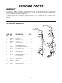
FAUCET ASSEMBLY
1
2
1
ITEM PART
NO. NO.
DESCRIPTION
QTY.
1.
KE50825-7
3/4" SPOUT . . . . . . . . . . . . . . . . . . . . . . . .1
2.
FA95022
RETAINING RING . . . . . . . . . . . . . . . . . . . .1
3.
FA05002-19
"O" RING . . . . . . . . . . . . . . . . . . . . . . . . . . .1
4.
KE51736
LONG FAUCET NUT . . . . . . . . . . . . . . . . .1
5.
SE50020
HOT WATER STEM ASSEMBLY . . . . . . . . .1
3
4
2
5
3
6
4
6
10
7
11
(DOUBLE PANTRY ONLY)
6.
SE50021
COLD WATER STEM ASSEMBLY . . . . . . . .1
7.
KE51401
SINGLE PANTRY BODY . . . . . . . . . . . . . . .1
KE50335
12
13
10
(C/W ITEM NO. 6)
8.
ADAPTER WASHER . . . . . . . . . . . . . . . . . .1
11
(SINGLE PANTRY ONLY)
12
13
9.
KE51403
9
8
DOUBLE PANTRY BODY . . . . . . . . . . . . . .1
(C/W ITEM NO. 5&6)
10.
SK00395-1
FAUCET MOUNTING BRACKET . . . . . . . .1
11.
FA11258
HEX CAP SCREW . . . . . . . . . . . . . . . . . . .2
12.
FA30505-1
WASHER . . . . . . . . . . . . . . . . . . . . . . . . . .2
13.
FA21008
HEX NUT . . . . . . . . . . . . . . . . . . . . . . . . . .2
14.
SE50447
WASHER HORSESHOE . . . . . . . . . . . . . . .1
7
14
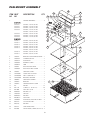
PAN MOUNT ASSEMBLY
28
ITEM PART
NO. NO.
DESCRIPTION
1.
HEATING ELEMENTS . . . . . . . . . . . .6
30 GALLON
SK50845-1
SK50845-2
SK50845-3
SK50845-4
SK50845-5
SK50845-6
SK50845-8
40 GALLON
SK50861-1
SK50861-2
SK50861-3
SK50861-4
SK50861-5
SK50861-6
SK50861-7
18
24
QTY.
9
11 18 10 27
24
8
14
ELEMENT, 2.00 KW, 480 VAC
ELEMENT, 2.67 KW, 416 VAC
ELEMENT, 2.00 KW, 416 VAC
ELEMENT, 2.67 KW, 240 VAC
ELEMENT, 2.00 KW, 208 VAC
ELEMENT, 2.00 KW, 240 VAC
ELEMENT, 2.67 KW, 208 VAC
ELEMENT, 2.67 KW, 480 VAC
12
13
21
12
26
23
18
17
16
19
22
20
7
15
ELEMENT, 4.00 KW, 480 VAC
ELEMENT, 3.00 KW, 480 VAC
ELEMENT, 4.00 KW, 416 VAC
ELEMENT, 3.00 KW, 416 VAC
ELEMENT, 4.00 KW, 240 VAC
ELEMENT, 3.00 KW, 208 VAC
ELEMENT, 3.00 KW, 240 VAC
ELEMENT, 4.00 KW, 208 VAC
6
18
5
3.
SK50932
BRACKET FOR THERMOCOUPLE . .1
4.
SK50958-1
CLAMPING PLATE . . . . . . . . . . . . . . .1
5.
SK50959-1
INSULATION . . . . . . . . . . . . . . . . . . .1
6.
SK50960-1
ELEMENT COVER . . . . . . . . . . . . . . .1
7.
SK50862-1
TRIM . . . . . . . . . . . . . . . . . . . . . . . . .1
8.
SK50961
ELECTRIC BOX WRAP . . . . . . . . . . .1
9.
SK50850-1
ELECTRICAL BOX COVER . . . . . . . .1
10.
SK50965
SIDE BOX COVER . . . . . . . . . . . . . . .1
11.
SK2489001
LIQUID TIGHT FITTING . . . . . . . . . . .1
12.
SK2490600
FULL COUPLING S.S. . . . . . . . . . . . .1
13.
SK2487800
BAYONET, ADAPTER . . . . . . . . . . . . .1
14.
SK00409
SIDE BOX ASSEMBLY . . . . . . . . . . . .1
15.
SK50963
BRACKET . . . . . . . . . . . . . . . . . . . . .1
16.
SK50962
THERMOCOUPLE COVER . . . . . . . .1
17.
F95
PALNUT . . . . . . . . . . . . . . . . . . . . . .91
18.
FA11144
SCREW, S.S. 10-32 X 1/4 . . . . . . . .46
19.
FA21008
HEX. NUT 1/4-20 . . . . . . . . . . . . . . . .3
20.
FA30505-1
WASHER, 1/4 . . . . . . . . . . . . . . . . . . .3
21.
SK50933-1
SENSOR . . . . . . . . . . . . . . . . . . . . . .1
22.
FA30505-3
WASHER . . . . . . . . . . . . . . . . . . . . . .1
23.
KE55069-7
HIGH LIMIT . . . . . . . . . . . . . . . . . . . .1
24.
SK50908-1
INSULATION, ELECTRICAL BOX . . .2
26.
KE55247
SILICON WASHER . . . . . . . . . . . . . . .2
27.
KE53735
WASHER . . . . . . . . . . . . . . . . . . . . . .1
28.
54833-4
SNAP-IN BUSHING . . . . . . . . . . . . . .2
29.
FA95088
HEX FLANGE, SCREW, 10-32 X 1/2 .2
8
4
3
1
29
20
19
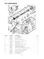
TILT COMPONENTS
32
33
24 25
57
26
24 25
23
20
56
20
16
18
19
17
20
22
20
21
29
21
1
39
2
3
9
36
35
11
34
4
5
58
8
40
41
42
43
44 47
45 48
46
30
31
27 28
55
10
4
5
7
19
12
13
14
37
15
59
52
49 53
50 54
51
38
ITEM NO.
PART NO.
DESCRIPTION
1.
KE51730
TILT SHAFT BEARING . . . . . . . . . . . . . . . . . . . . . . . . . . . . . . . . . . . . . . . . . . . . .1
QTY.
2.
FA31010
LOCK WASHER, 3/8 . . . . . . . . . . . . . . . . . . . . . . . . . . . . . . . . . . . . . . . . . . . . . .2
3.
FA20030
HEX NUT, 3/8-16 . . . . . . . . . . . . . . . . . . . . . . . . . . . . . . . . . . . . . . . . . . . . . . . . .2
4.
KE51007
LIMIT SWITCH, (POWER TILT) . . . . . . . . . . . . . . . . . . . . . . . . . . . . . . . . . . . . . .2
5.
FA10140
SCREW, 6-32 X 1 1/4, (POWER TILT) . . . . . . . . . . . . . . . . . . . . . . . . . . . . . . . . .4
7.
FA19201
SET SCREW, 3/8-24 X 1/2 . . . . . . . . . . . . . . . . . . . . . . . . . . . . . . . . . . . . . . . . . .1
8.
FA95048
WOODRUFF KEY . . . . . . . . . . . . . . . . . . . . . . . . . . . . . . . . . . . . . . . . . . . . . . . .1
9.
FA19177
HEX SOCKET SET SCREW, 5/16-24 X 1 . . . . . . . . . . . . . . . . . . . . . . . . . . . . . . .1
10.
FA20047
JAM NUT, 5/16-24 . . . . . . . . . . . . . . . . . . . . . . . . . . . . . . . . . . . . . . . . . . . . . . . .1
11.
KE00151
SEGMENT GEAR, (MANUAL TILT) . . . . . . . . . . . . . . . . . . . . . . . . . . . . . . . . . . .1
KE00279
SEGMENT GEAR, (POWER TILT) . . . . . . . . . . . . . . . . . . . . . . . . . . . . . . . . . . . .1
12.
KE50312
LIMIT SWITCH TURN OFF BRACKET, (POWER TILT) . . . . . . . . . . . . . . . . . . . .2
13.
FA11258
HEX SCREW, 1/4-20 X 3/4, (POWER TILT) . . . . . . . . . . . . . . . . . . . . . . . . . . . . .4
14.
FA31029
SPLIT LOCKWASHER, (POWER TILT) . . . . . . . . . . . . . . . . . . . . . . . . . . . . . . . .4
15.
FA30505-1
WASHER, 1/4, (POWER TILT) . . . . . . . . . . . . . . . . . . . . . . . . . . . . . . . . . . . . . . .4
16.
KE50441
SHAFT, (POWER TILT) . . . . . . . . . . . . . . . . . . . . . . . . . . . . . . . . . . . . . . . . . . . . .1
KE50375
SHAFT, (MANUAL TILT) . . . . . . . . . . . . . . . . . . . . . . . . . . . . . . . . . . . . . . . . . . .1
9
TILT COMPONENTS (continued)
17.
KE50315
WORM . . . . . . . . . . . . . . . . . . . . . . . . . . . . . . . . . . . . . . . . . . . . . . . . . . . . . . . . .1
18.
FA95005
TENSION PIN . . . . . . . . . . . . . . . . . . . . . . . . . . . . . . . . . . . . . . . . . . . . . . . . . . .1
19.
KE52193
THRUST BEARING SPACER . . . . . . . . . . . . . . . . . . . . . . . . . . . . . . . . . . . . . . . .2
20.
KE52192
THRUST WASHER . . . . . . . . . . . . . . . . . . . . . . . . . . . . . . . . . . . . . . . . . . . . . . . .4
21.
KE52191
ROLLER BEARING . . . . . . . . . . . . . . . . . . . . . . . . . . . . . . . . . . . . . . . . . . . . . . .2
22.
FA19500-2
WASHER, 1 1/2 X 13/16 X 1/8 . . . . . . . . . . . . . . . . . . . . . . . . . . . . . . . . . . . . . . .2
23.
FA95008
JAM NUTS . . . . . . . . . . . . . . . . . . . . . . . . . . . . . . . . . . . . . . . . . . . . . . . . . . . . . .2
24.
KE50582
1/2 COUPLING WITH 5/8 BORE, (POWER TILT) . . . . . . . . . . . . . . . . . . . . . . . .2
25.
FA95014
SET SCREW 1/4-2 X 3/8, (POWER TILT) . . . . . . . . . . . . . . . . . . . . . . . . . . . . . . .1
26.
KE50583
COUPLING INSERT, (POWER TILT) . . . . . . . . . . . . . . . . . . . . . . . . . . . . . . . . . .1
27.
KE52832-4
DC MOTOR, (POWER TILT) . . . . . . . . . . . . . . . . . . . . . . . . . . . . . . . . . . . . . . . .1
28.
KE54829-4
BRACKET FOR MOTOR, (POWER TILT) . . . . . . . . . . . . . . . . . . . . . . . . . . . . . . .1
29.
FA11258
HEX SCREW, 1/4-20 X 3/4, (POWER TILT) . . . . . . . . . . . . . . . . . . . . . . . . . . . . .7
30.
FA30505-1
WASHER, 1/4, (POWER TILT) . . . . . . . . . . . . . . . . . . . . . . . . . . . . . . . . . . . . . . .7
31.
FA21008
HEX NUT, 1/4 - 20, (POWER TILT) . . . . . . . . . . . . . . . . . . . . . . . . . . . . . . . . . . .7
32.
KE00508
HANDWHEEL ASSEMBLY, (MANUAL TILT) . . . . . . . . . . . . . . . . . . . . . . . . . . . .1
33.
FA19186
SET SCREW, HANDWHEEL, (MANUAL TILT) . . . . . . . . . . . . . . . . . . . . . . . . . . .1
34.
KE50294-1
MERCURY SWITCH . . . . . . . . . . . . . . . . . . . . . . . . . . . . . . . . . . . . . . . . . . . . . .1
35.
KE50295-1
CLIP . . . . . . . . . . . . . . . . . . . . . . . . . . . . . . . . . . . . . . . . . . . . . . . . . . . . . . . . . . .1
36.
FA15018-1
MACHINE SCREW . . . . . . . . . . . . . . . . . . . . . . . . . . . . . . . . . . . . . . . . . . . . . . .1
37.
FA19184
3/8-16 X 3/8 SET SCREW . . . . . . . . . . . . . . . . . . . . . . . . . . . . . . . . . . . . . . . . . .1
38.
SK50047-1
TRUNNION COLLAR . . . . . . . . . . . . . . . . . . . . . . . . . . . . . . . . . . . . . . . . . . . . . .1
39.
KE53838-25
TRANSFORMER . . . . . . . . . . . . . . . . . . . . . . . . . . . . . . . . . . . . . . . . . . . . . . . . .1
40.
KE53444
BRACKET . . . . . . . . . . . . . . . . . . . . . . . . . . . . . . . . . . . . . . . . . . . . . . . . . . . . . .1
41.
FA11091
SCREW, 8-32 X 3/8 . . . . . . . . . . . . . . . . . . . . . . . . . . . . . . . . . . . . . . . . . . . . . . .2
42.
KE50473
GROUND LUG . . . . . . . . . . . . . . . . . . . . . . . . . . . . . . . . . . . . . . . . . . . . . . . . . .1
43.
F900
K-LOCK NUT, 1/4-20 . . . . . . . . . . . . . . . . . . . . . . . . . . . . . . . . . . . . . . . . . . . . . .1
44.
KE52936-8
FUSE, 1.25 AMP . . . . . . . . . . . . . . . . . . . . . . . . . . . . . . . . . . . . . . . . . . . . . . . . .1
45.
KE52936-6
FUSE, 3 AMP . . . . . . . . . . . . . . . . . . . . . . . . . . . . . . . . . . . . . . . . . . . . . . . . . . . .1
46.
KE51139
FUSE HOLDER . . . . . . . . . . . . . . . . . . . . . . . . . . . . . . . . . . . . . . . . . . . . . . . . . .2
47.
SK50945-1
BRACKET . . . . . . . . . . . . . . . . . . . . . . . . . . . . . . . . . . . . . . . . . . . . . . . . . . . . . .1
48.
F900
K-LOCK NUT, 1/4-20 . . . . . . . . . . . . . . . . . . . . . . . . . . . . . . . . . . . . . . . . . . . . . .1
49.
KE50377
TERMINAL BLOCK . . . . . . . . . . . . . . . . . . . . . . . . . . . . . . . . . . . . . . . . . . . . . . .3
50.
KE50376
TERMINAL BLOCK END . . . . . . . . . . . . . . . . . . . . . . . . . . . . . . . . . . . . . . . . . . .1
51.
FA11091
SCREW, 8-32 X 3/8 . . . . . . . . . . . . . . . . . . . . . . . . . . . . . . . . . . . . . . . . . . . . . . .2
52.
KE50374
TERMINAL BLOCK BRACKET . . . . . . . . . . . . . . . . . . . . . . . . . . . . . . . . . . . . . .1
53.
FA21008
HEX NUT, 1/4 - 20 . . . . . . . . . . . . . . . . . . . . . . . . . . . . . . . . . . . . . . . . . . . . . . . .2
54.
FA30505-1
WASHER, 1/4 . . . . . . . . . . . . . . . . . . . . . . . . . . . . . . . . . . . . . . . . . . . . . . . . . . .2
55.
KE54833-1
SNAP-IN BUSHING . . . . . . . . . . . . . . . . . . . . . . . . . . . . . . . . . . . . . . . . . . . . . .1
56.
KE50579-1
CIRCUIT BREAKER . . . . . . . . . . . . . . . . . . . . . . . . . . . . . . . . . . . . . . . . . . . . . . .1
FA05002-34
"O" RING, CIRCUIT BREAKER . . . . . . . . . . . . . . . . . . . . . . . . . . . . . . . . . . . . . .1
KE50580
WATER RESISTANT BOOT . . . . . . . . . . . . . . . . . . . . . . . . . . . . . . . . . . . . . . . . .1
57.
KE53137-3
MERCURY SWITCH . . . . . . . . . . . . . . . . . . . . . . . . . . . . . . . . . . . . . . . . . . . . . .1
KE53184
CONTACT SECTION HOLDER (LATCH) . . . . . . . . . . . . . . . . . . . . . . . . . . . . . . .1
KE53138-1
CONTACT BLOCK . . . . . . . . . . . . . . . . . . . . . . . . . . . . . . . . . . . . . . . . . . . . . . .4
58.
KE51711
BEARING, NEEDLE . . . . . . . . . . . . . . . . . . . . . . . . . . . . . . . . . . . . . . . . . . . . . . .1
59.
FA95007-1
RETAINING RING . . . . . . . . . . . . . . . . . . . . . . . . . . . . . . . . . . . . . . . . . . . . . . . .1
10
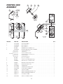
CONTROL BOX
ASSEMBLY
9
5
1
2
3
4
6
7
WARNING: Improper installation,
adjustment, alteration, service or
maintenance can cause property
damage, injury or death. Read the
installation, operating and maintenance
instructions thoroughly before installing
or servicing this equipment.
8
AVERTISSEMENT: Une mauvaise
installation, un réglage inadapté ou
un manque d'entretien peuvent
occasionner
des
dommages
matériels ou corporels. Il est donc
indispensable de lire attentivement
les notices avant l'installation ou
l'entretien.
WARNUNG: Unsachgemäßer Einbau,
Einstellung, Veränderung, Bedienung oder
Wartung
können
Sachschaden,
Verletzungen oder Tod verursachen. Lesen
Sie bitte die Einbau-, Bedienungs- und
Wartungsanleitungen genau durch, ehe Sie
dieses Gerät einbauen oder bedienen.
SECTION
A-A
ADVERTENCIA: La instalación, ajuste,
alteración, servicio o mantenimiento
incorrectos pueden causar daños a la
propiedad, lesiones o muerte. Lea
detenidamente las instrucciones de
instalación, operación y mantenimiento antes
de instalar o dar servicio a este equipo.
HOT
CHAUD
ATTENZIONE: Installazione, regolazione,
modifiche, riparazioni o manutenzione
erronee possono causare danni, infortuni o
morte. Leggere attentamente le istruzioni per
l'installazione, il funzionamento e la
manutenzione prima di installare o riparare
questo macchinario.
!
SECTION
B-B
B
A
1
13
2
SK95063
C
16
11
10
9
15
12
8
14
9
A
B
SECTION
C-C
C
ITEM NO.
PART NO.
DESCRIPTION
1.
SK2138700
KNOB ASSEMBLY . . . . . . . . . . . . . . . . . . . . . . . . . . . . . . . . . . . . . . . . . . . . . . . .1
2.
SK2360700
DIAL INSERT °F . . . . . . . . . . . . . . . . . . . . . . . . . . . . . . . . . . . . . . . . . . . . . . . . .1
SK2360701
DIAL INSERT °C . . . . . . . . . . . . . . . . . . . . . . . . . . . . . . . . . . . . . . . . . . . . . . . . .1
KE51005
RUBBER BOOT. #N9030 X 1/4 . . . . . . . . . . . . . . . . . . . . . . . . . . . . . . . . . . . . . .1
3.
4.
QTY.
SK2498399
POTENTIOMETER SHAFT ASSEMBLY . . . . . . . . . . . . . . . . . . . . . . . . . . . . . . . .1
SK2166800
SK2167000
SK2167100
SK2167200
SK2167300
SK2382800
POTENTIOMETER SHAFT . . . . . . . . . . . . . . . . . . . . . . . . . . . . . . . . . . . . . . . . . . . . . . . . . . . . . .1
TENSION PIN . . . . . . . . . . . . . . . . . . . . . . . . . . . . . . . . . . . . . . . . . . . . . . . . . . . . . . . . . . . . . . . .1
WASHER, BOWED/SPRING . . . . . . . . . . . . . . . . . . . . . . . . . . . . . . . . . . . . . . . . . . . . . . . . . . . . .1
RETAINING RING, SP-NR #R1000-25 . . . . . . . . . . . . . . . . . . . . . . . . . . . . . . . . . . . . . . . . . . . . .1
PANEL BEARING . . . . . . . . . . . . . . . . . . . . . . . . . . . . . . . . . . . . . . . . . . . . . . . . . . . . . . . . . . . . .1
RETAINING RING CLIP . . . . . . . . . . . . . . . . . . . . . . . . . . . . . . . . . . . . . . . . . . . . . . . . . . . . . . . .1
5.
FA21006
NUT, S.S. F#10-24 . . . . . . . . . . . . . . . . . . . . . . . . . . . . . . . . . . . . . . . . . . . . . . . .2
6.
FA32022
TOOTH LOCK WASHER #10 S.S. . . . . . . . . . . . . . . . . . . . . . . . . . . . . . . . . . . .2
7.
FA40000-6
#10-24 X 3/8 S.S. WELD STUD . . . . . . . . . . . . . . . . . . . . . . . . . . . . . . . . . . . . . .2
8.
SK50903
BRACKET, INDICATOR LIGHT . . . . . . . . . . . . . . . . . . . . . . . . . . . . . . . . . . . . . .1
INCLUDES
{
9.
SK50905-1
HEAT INDICATOR, 28V . . . . . . . . . . . . . . . . . . . . . . . . . . . . . . . . . . . . . . . . . . . .1
10.
SK2142002
THERMOSTAT . . . . . . . . . . . . . . . . . . . . . . . . . . . . . . . . . . . . . . . . . . . . . . . . . . .1
11.
SK2159300
THERMOSTAT INSULATOR . . . . . . . . . . . . . . . . . . . . . . . . . . . . . . . . . . . . . . . . .1
12.
SK2491500
STOP PLATE ASSEMBLY . . . . . . . . . . . . . . . . . . . . . . . . . . . . . . . . . . . . . . . . . .1
13.
SK95063
CAUTION LABEL . . . . . . . . . . . . . . . . . . . . . . . . . . . . . . . . . . . . . . . . . . . . . . . .1
14.
SK90125-2
WIRING DIAGRAM MANUAL TILT . . . . . . . . . . . . . . . . . . . . . . . . . . . . . . . . . . .1
SK90125-3
WIRING DIAGRAM POWER TILT . . . . . . . . . . . . . . . . . . . . . . . . . . . . . . . . . . . .1
15.
SK90125-1
CONTROLS LABEL . . . . . . . . . . . . . . . . . . . . . . . . . . . . . . . . . . . . . . . . . . . . . . .1
16.
SK2474103
SWITCH, POWER ON/OFF . . . . . . . . . . . . . . . . . . . . . . . . . . . . . . . . . . . . . . . . .1
11
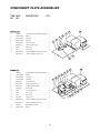
COMPONENT PLATE ASSEMBLIES
ITEM PART
NO. NO.
MANUAL TILT
SK00411
2.
SK2475500
3.
SK2475600
4.
SK2475700
5.
KE50750-7
7.
KE54833-4
11.
F904
12.
F10
13.
KE53838-10
KE53838-11
1.
DESCRIPTION
QTY.
5
COMPONENT PLATE WELDMENT
2
RELAY . . . . . . . . . . . . . . . . . . . . . . . .1
4
HOLDER . . . . . . . . . . . . . . . . . . . . . .1
SPRING
. . . . . . . . . . . . . . . . . . . . . .1
13
7
.1
3
1
CONTACTOR . . . . . . . . . . . . . . . . . .2
SNAP-IN BUSHING . . . . . . . . . . . . .1
6-32 X 5/8 . . . . . . . . . . . . . . . . . . . . .2
8-32 X 3/8 . . . . . . . . . . . . . . . . . . . . .8
TRANSFORMER, 208-240V, 480V . . .1
TRANSFORMER, 380-415V . . . . . . . .1
12
11
POWER TILT
1.
SK00411
2.
SK2475500
3.
SK2475600
4.
SK2475700
5.
KE50750-7
7.
KE54833-4
8.
KE02185-1
9.
SK50930
10.
F903
11.
F904
12.
F10
13.
FA11504
14.
KE53838-10
KE53838-11
15.
KE50581
16.
KE50753-10
5
COMPONENT PLATE WELDMENT
.1
2
4
RELAY . . . . . . . . . . . . . . . . . . . . . . . .1
3
HOLDER . . . . . . . . . . . . . . . . . . . . . .1
SPRING
. . . . . . . . . . . . . . . . . . . . . .1
14
7
9
1
CONTACTOR . . . . . . . . . . . . . . . . . .2
SNAP-IN BUSHING . . . . . . . . . . . . .1
COMPONENT PLATE . . . . . . . . . . . .1
RESISTOR
. . . . . . . . . . . . . . . . . . . .1
4 X 3/8 PAN PHIL.
15
. . . . . . . . . . . . . .2
16
8
6-32 X 5/8 . . . . . . . . . . . . . . . . . . . . .2
8-32 X 3/8 . . . . . . . . . . . . . . . . . . . . .8
10-24 X 3/8 . . . . . . . . . . . . . . . . . . . .2
TRANSFORMER, 208-240V, 480V . . .1
TRANSFORMER, 380-415V . . . . . . . .1
BRIDGE RECTIFIER . . . . . . . . . . . . .1
RELAY . . . . . . . . . . . . . . . . . . . . . . . .2
12
13
10
23 24 25 26
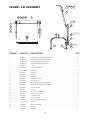
FRAME / LID ASSEMBLY
2
19 20 21 22
1
4 18
9
5
10
11
17
6
OPEN END OF
SPRING TO BE
LOCATED ON TOP
7
13
12
8
APPLY
REMOVABLE
LOCKTITE
27
ITEM NO.
1.
2.
PART NO.
DESCRIPTION
QTY.
SK00392-1
FRAME WELDMENT (30 GALLON) . . . . . . . . . . . . . . . . . . . . . . . . . . . . . . . . . .1
SK00392-3
FRAME WELDMENT (40 GALLON) . . . . . . . . . . . . . . . . . . . . . . . . . . . . . . . . . .1
SK2457192
LID ASSEMBLY (30 GALLON) . . . . . . . . . . . . . . . . . . . . . . . . . . . . . . . . . . . . . .1
SK2457193
LID ASSEMBLY (40 GALLON) . . . . . . . . . . . . . . . . . . . . . . . . . . . . . . . . . . . . . .1
4.
KE50187-1
CAP . . . . . . . . . . . . . . . . . . . . . . . . . . . . . . . . . . . . . . . . . . . . . . . . . . . . . . . . . . .2
5.
SK00394-1
HOOK WELDMENT . . . . . . . . . . . . . . . . . . . . . . . . . . . . . . . . . . . . . . . . . . . . . . .2
6.
SK2452300
SPRING . . . . . . . . . . . . . . . . . . . . . . . . . . . . . . . . . . . . . . . . . . . . . . . . . . . . . . . .2
7.
FA95087-1
EYE BOLT . . . . . . . . . . . . . . . . . . . . . . . . . . . . . . . . . . . . . . . . . . . . . . . . . . . . . .2
8.
FA20008
HEX NUT . . . . . . . . . . . . . . . . . . . . . . . . . . . . . . . . . . . . . . . . . . . . . . . . . . . . . . .2
9.
KE53573-1
BEARING . . . . . . . . . . . . . . . . . . . . . . . . . . . . . . . . . . . . . . . . . . . . . . . . . . . . . . .2
10.
FA15019-4
SHOULDER BOLT . . . . . . . . . . . . . . . . . . . . . . . . . . . . . . . . . . . . . . . . . . . . . . . .2
11.
FA21501-2
ACORN NUT . . . . . . . . . . . . . . . . . . . . . . . . . . . . . . . . . . . . . . . . . . . . . . . . . . . .2
12.
KE00099
ADJUSTABLE FOOT (FLANGED) . . . . . . . . . . . . . . . . . . . . . . . . . . . . . . . . . . . .2
13.
KE50249-1
FOOT ADJUSTOR (W/O FLANGE) . . . . . . . . . . . . . . . . . . . . . . . . . . . . . . . . . . .2
17.
FA31029
LOCKWASHER . . . . . . . . . . . . . . . . . . . . . . . . . . . . . . . . . . . . . . . . . . . . . . . . . .2
18.
FA11054
SCREW . . . . . . . . . . . . . . . . . . . . . . . . . . . . . . . . . . . . . . . . . . . . . . . . . . . . . . . .4
19.
SK2459299
COUPLING ASSEMBLY . . . . . . . . . . . . . . . . . . . . . . . . . . . . . . . . . . . . . . . . . . . .1
20
FA21024
HEX NUT (5/16-18) . . . . . . . . . . . . . . . . . . . . . . . . . . . . . . . . . . . . . . . . . . . . . . .2
21.
FA31030
LOCKWASHER . . . . . . . . . . . . . . . . . . . . . . . . . . . . . . . . . . . . . . . . . . . . . . . . . .2
22.
FA30055
FLAT WASHER . . . . . . . . . . . . . . . . . . . . . . . . . . . . . . . . . . . . . . . . . . . . . . . . . .2
23.
SK00054
VENT COVER ASSEMBLY . . . . . . . . . . . . . . . . . . . . . . . . . . . . . . . . . . . . . . . . . .1
24.
SK2211200
SPACER . . . . . . . . . . . . . . . . . . . . . . . . . . . . . . . . . . . . . . . . . . . . . . . . . . . . . . . .1
25.
FA95081-1
BOLT, MODIFIED . . . . . . . . . . . . . . . . . . . . . . . . . . . . . . . . . . . . . . . . . . . . . . . . .1
26.
SK50179
WASHER . . . . . . . . . . . . . . . . . . . . . . . . . . . . . . . . . . . . . . . . . . . . . . . . . . . . . . .1
27.
FA30504
WASHER . . . . . . . . . . . . . . . . . . . . . . . . . . . . . . . . . . . . . . . . . . . . . . . . . . . . . . .2
13
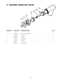
2" TANGENT DRAW-OFF VALVE
7
6
5
4
3
2
1
ITEM NO.
PART NO.
DESCRIPTION
QTY.
1. - 7.
1.
2.
3.
4.
5.
6.
7.
KE50972-B
FA95049
KE527551
KE52754
KE52753
KE52752
FA00111
KE52751
DRAW-OFF ASSEMBLY . . . . . . . . . . . . . . . . . . . . . . . . . . . . . . . . . . . . . . . . . . . .1
WING NUT . . . . . . . . . . . . . . . . . . . . . . . . . . . . . . . . . . . . . . . . . . . . . . . . . . . . . .1
KNOB . . . . . . . . . . . . . . . . . . . . . . . . . . . . . . . . . . . . . . . . . . . . . . . . . . . . . . . . .1
HEX NUT . . . . . . . . . . . . . . . . . . . . . . . . . . . . . . . . . . . . . . . . . . . . . . . . . . . . . . .1
RETAINER . . . . . . . . . . . . . . . . . . . . . . . . . . . . . . . . . . . . . . . . . . . . . . . . . . . . . .1
PISTON . . . . . . . . . . . . . . . . . . . . . . . . . . . . . . . . . . . . . . . . . . . . . . . . . . . . . . . .1
"O" RING . . . . . . . . . . . . . . . . . . . . . . . . . . . . . . . . . . . . . . . . . . . . . . . . . . . . . . .1
VALVE BODY . . . . . . . . . . . . . . . . . . . . . . . . . . . . . . . . . . . . . . . . . . . . . . . . . . .2
14
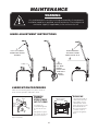
MAINTENANCE
WARNING:
!
Any maintenance or service involving disassembly of components
should be made by a qualified service technician. Ensure electrical
and water supply (if applicable) to the unit are shut off.
HINGE ADJUSTMENT INSTRUCTIONS
1.
3.
FULLY LIFT COVER
TO RELEASE SPRING
TENSION
WHEN PROPERLY
ADJUSTED, COVER
SHOULD REST AT 70˚
2.
SPRING
USING A
7/16" DEEP
SOCKET
ADJUST LEFT
AND RIGHT
BOLTS
EVENLY
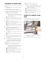
LUBRICATION PROCEDURE
Lubricate the following parts every three months to
insure smooth operation and reduce wear.
TRUNNION
HOUSING,
WORM SCREW
AND TILT GEAR
Adjusting
Screw
Worm
Screw and
Tilt
Gear
Cross
Bar
TRUNNIONS
Trunnion Housing
Grease Nipple
These parts are
accessed through the
top cover of the console.
Apply grease to gear
teeth. Check for excessive play and adjust with adjusting screw located on
top of cross bar.
15
On the left hand side of
the skillet there are two
grease nipples on the
top back portion of the
trunnion housing. On the
right hand side of the
kettle you must remove
the console cover to
access the two grease
nipples.
11. With the Tilt switch in the Down position
SEQUENCE OF OPERATIONS
■ 120 VAC is sent to the Bridge Rectifier
When using these instructions refer to the SEL-TI wiring
schematic.
1.
Supply Voltage is sent to the primary of the 120
VAC transformer.
2.
Supply voltage is sent to the normally open contacts of the Heat Contactors, C 1 and C2.
3.
120 VAC is sent from the secondary of the 120VAC
transformer through the 3 amp fuse to
❏ 115 DC is sent from the rectifier through the
30-ohm resistor to the normally open RY 10
and RY 11 relay contacts.
■ 120 VAC is sent to the RY11 relay coil.
■ The normally open RY 11 contact close and the
polarity of the 90 VDC is reversed.
■ The DC motor is energized and the skillet lowers
until the switch is released or
■ The primary of the 24 VAC transformer
❏ 24 VAC is sent from the secondary of the
24VAC transformer through the 1.25 amp fuse
to the on/off switch.
POWER TILT MANUAL OVERRIDE
■ Contacts of the R1 Heat Relay
4.
120 VAC is sent from the secondary of the 120 VAC
transformer to the optional Power Tilt Circuit (See
step 9).
5.
With the On/Off switch in the On position.
In case of power failure or malfunction the skillet pan
can be tilted manually following these instructions.
■ 24 VAC is sent through the normally closed high
limit switch to the mercury switch..
MANUAL
TILT
SHAFT
■ If the skillet is in the down position then 24 VAC
is sent through mercury switch to pin 9 on the thermostat.
6.
If the steamer is calling for heat the 24 VAC is sent
from pin number 10 to RI Heat Relay.
10 MM
6 POINT
SOCKET
■ The normally open contacts of the Heat relay
close sending 120 VAC to the Heat contactor coils
C 1 and C2.
7.
The Contactor close and supply Voltage is sent to
the elements.
■ The elements heat until the thermostat is satisfied.
8.
When thermostat is satisfied, 24 VAC is removed
from pin 10 on the thermostat and the heat circuit
is de-energized.
9.
If the skillet has the optional Power Tilt option and
is in the down position, 120 VAC is sent from the
secondary of the 120 VAC transformer through the
circuit breaker and the up limit switch to the tilt
switch.
10. With the tilt switch in switch in the Up position
■ 120 VAC is sent to the Bridge Rectifier
❏ 115 VDC is sent from the rectifier through
the 30-ohm resistor to the normally open
RY10 and RYI I relay contacts.
■ 120 VAC is sent to the RY10 relay coil.
■ The normally open RY10 contact close and 90
VDC is sent to the DC motor
■ The DC motor is energized and the skillet tilts
until the switch is released or the up limit switch
opens.
16
1.
Fit a 10 MM 6 POINT SOCKET over the MANUAL
TILT SHAFT as shown above.
2.
Turn socket wrench clockwise to empty contents.
SPARE PARTS LIST
PART NO.
DESCRIPTION
QTY.
HEATING ELEMENTS . . . . . . . . . . . . . . . . . . . . . . . . . . . . . . . . . . . . . . . . . . . . . . . . . . . . . . . . . . . . . . . . . . . . . . . . . . . . . . . . 6
30 GALLON
SK50845-1
ELEMENT, 2.00 KW, 480 VAC
SK50845-2
ELEMENT, 2.67 KW, 416 VAC
SK50845-3
ELEMENT, 2.00 KW, 416 VAC
SK50845-4
ELEMENT, 2.67 KW, 240 VAC
ELEMENT, 2.00 KW, 208 VAC
SK50845-5
ELEMENT, 2.00 KW, 240 VAC
SK50845-6
ELEMENT, 2.67 KW, 208 VAC
SK50845-8
ELEMENT, 2.67 KW, 480 VAC
40 GALLON
SK50861-1
ELEMENT, 4.00 KW, 480 VAC
SK50861-2
ELEMENT, 3.00 KW, 480 VAC
SK50861-3
ELEMENT, 4.00 KW, 416 VAC
SK50861-4
ELEMENT, 3.00 KW, 416 VAC
SK50861-5
ELEMENT, 4.00 KW, 240 VAC
ELEMENT, 3.00 KW, 208 VAC
SK50861-6
ELEMENT, 3.00 KW, 240 VAC
SK50861-7
ELEMENT, 4.00 KW, 208 VAC
SK50933-1
SENSOR . . . . . . . . . . . . . . . . . . . . . . . . . . . . . . . . . . . . . . . . . . . . . . . . . . . . . . . . . . . . . . . . . . . . . . . . . . .1
KE55069-7
SAFETY THERMOSTAT . . . . . . . . . . . . . . . . . . . . . . . . . . . . . . . . . . . . . . . . . . . . . . . . . . . . . . . . . . . . . . . .1
SK2475500
RELAY . . . . . . . . . . . . . . . . . . . . . . . . . . . . . . . . . . . . . . . . . . . . . . . . . . . . . . . . . . . . . . . . . . . . . . . . . . . .1
KE50750-7
CONTACTOR . . . . . . . . . . . . . . . . . . . . . . . . . . . . . . . . . . . . . . . . . . . . . . . . . . . . . . . . . . . . . . . . . . . . . . .2
KE53838-10
TRANSFORMER, 208-240V, 480V . . . . . . . . . . . . . . . . . . . . . . . . . . . . . . . . . . . . . . . . . . . . . . . . . . . . . . .1
KE53838-11
TRANSFORMER, 380-415V . . . . . . . . . . . . . . . . . . . . . . . . . . . . . . . . . . . . . . . . . . . . . . . . . . . . . . . . . . . .1
KE53838-25
TRANSFORMER . . . . . . . . . . . . . . . . . . . . . . . . . . . . . . . . . . . . . . . . . . . . . . . . . . . . . . . . . . . . . . . . . . . . .1
KE52936-8
FUSE, 1.25 AMP . . . . . . . . . . . . . . . . . . . . . . . . . . . . . . . . . . . . . . . . . . . . . . . . . . . . . . . . . . . . . . . . . . . . .1
KE52936-6
FUSE, 3 AMP . . . . . . . . . . . . . . . . . . . . . . . . . . . . . . . . . . . . . . . . . . . . . . . . . . . . . . . . . . . . . . . . . . . . . . .1
SK2498399
POTENTIOMETER SHAFT ASSEMBLY . . . . . . . . . . . . . . . . . . . . . . . . . . . . . . . . . . . . . . . . . . . . . . .1
INCLUDES: . . . . . . . . . . . . . . . . . . . . . . . . . . . . . . . . . . . . . . . . . . . . . . . . . . . . . . . . . . . . . . . . . . . . . . . . . . . . . . . . . .
SK2166800
SK2167000
SK2167100
SK2167200
SK2167300
SK2382800
POTENTIOMETER SHAFT . . . . . . . . . . . . . . . . . . . . . . . . . . . . . . . . . . . . . . . . . . . . . . . . . . . . . . . . . . . . . . . . . . . . . . . .1
TENSION PIN . . . . . . . . . . . . . . . . . . . . . . . . . . . . . . . . . . . . . . . . . . . . . . . . . . . . . . . . . . . . . . . . . . . . . . . . . . . . . . . . . .1
WASHER, BOWED/SPRING . . . . . . . . . . . . . . . . . . . . . . . . . . . . . . . . . . . . . . . . . . . . . . . . . . . . . . . . . . . . . . . . . . . . . . .1
RETAINING RING, SP-NR #R1000-25 . . . . . . . . . . . . . . . . . . . . . . . . . . . . . . . . . . . . . . . . . . . . . . . . . . . . . . . . . . . . . . .1
PANEL BEARING . . . . . . . . . . . . . . . . . . . . . . . . . . . . . . . . . . . . . . . . . . . . . . . . . . . . . . . . . . . . . . . . . . . . . . . . . . . . . . .1
RETAINING RING CLIP . . . . . . . . . . . . . . . . . . . . . . . . . . . . . . . . . . . . . . . . . . . . . . . . . . . . . . . . . . . . . . . . . . . . . . . . . .1
SK50905-1
HEAT INDICATOR, 28V . . . . . . . . . . . . . . . . . . . . . . . . . . . . . . . . . . . . . . . . . . . . . . . . . . . . . . . . . . .1
SK2142002
THERMOSTAT . . . . . . . . . . . . . . . . . . . . . . . . . . . . . . . . . . . . . . . . . . . . . . . . . . . . . . . . . . . . . . . . . .1
SK2474103
SWITCH, POWER ON/OFF . . . . . . . . . . . . . . . . . . . . . . . . . . . . . . . . . . . . . . . . . . . . . . . . . . . . . . . .1
17
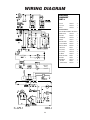
WIRING DIAGRAM
ELECTRICAL
COMPONENT
PART #s
FUSE 3A
KE52936-6
10
FUSE 1.25A
KE52936-8
10
RELAY 1
SK2475500
12
HEATING ELEMENTS -
SEE "PAN MOUNT ASSEMBLY" ON PAGE # 8
SENSOR
MERCURY
SWITCH
TILT SWITCH
RESISTOR
18
ON/OFF SWITCH
SK2474103
11
HIGH LIMIT
KE55069-7
8
THERMOSTAT
SK2142002
11
SENSOR
SK50933-1
8
HEAT INDICATOR
SK50905-1
16
CIRCUIT BREAKER
KE50579-1
10
MERCURY SWITCH
KE50294-1
10
LIMIT SWITCH
KE51007
9
RY10 (RELAY)
KE50753-10
12
RY11 (RELAY)
KE50753-10
12
DC MOTOR
KE52832-4
11
BRIDGE RECTIFIER
KE50581
12
RESISTOR
SK50930
12
TILT SWITCH
- SECTION
- CONTACT BLOCK
KE53137-3
KE53184
KE53138-1
11
11
11
✔
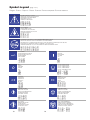
Symbol Legend
(page 1 of 2)
❐ English ❐ French ❐ Spanish
❐ Italian ❐ German ❐ Chinese-Simplified ❐ Chinese-Traditional
✔
✔
✔
RISK OF ELECTRICAL SHOCK
DANGER DE SECOUSSE ÉLECTRIQUE
PELIGRO DE ELECTROCHOQUE
PERICOLO DI SCOSSA
STROMSCHLAG-GEFAHR
✔
✔
✔
✔
SPLASHPROOF
ANTIÉCLABOUSSURES
A PRUEBA DE SALPICADURAS
PROTETTO CONTRO GLI SPRUZZI
SPRITZWASSERDICHT
✔
✔
✔
✔
DISCONNECT ELECTRICAL SUPPLY BEFORE WORKING ON KETTLE
COUPER LE COURANT AVANT D'INTERVENIR SUR L'ÉQUIPEMENT
DESCONECTAR LA ALIMENTACION ELECTRICA ANTES DE REALIZAR TRABAJOS EN EL EQUIPO
DISINSERIRE LA CORRENTE PRIMA DI LAVORARE SULLA MACCHINA
STROMVERSORGUNG AUSSCHALTEN, BEVOR AM GERÄT GEARBEITET WIRD
✔
✔
✔
✔
✔
✔
✔
MAIN POWER
ALIMENTATION ÉLECTRIQUE
ALIMENTACION PRINCIPAL
ALIMENTAZIONE
HAUPTSTROM
✔
ON
MARCHE
ENCENDIDO
ACCESO
AN
✔
✔
✔
✔
OFF
ARRÊT
APAGADO
SPENTO
AUS
19
✔
PAUSE, INTERRUPTION
PAUSE, INTERRUPTION
PAUSA, INTERRUPCION
PAUSA, INTERRUZIONE
PAUSE, UNTERBRECHUNG
✔
CONTINUE
CONTINUER
CONTINUAR
CONTINUA
WEITER
RESET
RÉENCLENCHER
RECONECTAR
RESET
NULLSTELLEN
START OF ACTION
DÉBUT DE L'ACTION
INICIAR FUNCIONAMIENTO
INIZIO OPERAZIONE
FUNKTION STARTEN
STOP OF ACTION
ARRÊT DE L'ACTION
PARAR FUNCIONAMIENTO
ARRESTO OPERAZIONE
FUNKTION STOPPEN
FAST START
DÉMARRAGE RAPIDE
INICIO RAPIDO
AVVIAMENTO RAPIDO
SCHNELLER START
FAST STOP, EMERGENCY
ARRÊT RAPIDE D'URGENCE
PARADA RAPIDA, EMERGENCIA
ARRESTO RAPIDO, EMERGENZA
SCHNELLER STOPP, NOTFALL
19
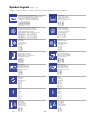
Symbol Legend
(page 2 of 2)
❐ English
❐ French ❐ Spanish ❐ Italian ❐ German ❐ Chinese-Simplified ❐ Chinese-Traditional
✔
AUTOMATIC TEMPERATURE CONTROL
COMMANDE AUTOMATIQUE DE LA TEMPÉRATURE
AJUSTE AUTOMATICO DE TEMPERATURA
CONTROLLO AUTOMATICO TEMPERATURA
AUTOMATISCHE TEMPERATURREGELUNG
LOW WATER
NIVEAU BAS DE L'EAU
NIVEL DE AGUA BAJO
LIVELLO BASSO
WASSERSTAND NIEDRIG
✔
✔
✔
BURNER AND/OR ELEMENT ENERGIZED
BRÛLEUR ET/OU ÉLÉMENT ALLUMÉ
QUEMADOR O ELEMENTO ENCENDIDO
FIAMMA E/O ELEMENTO ATTIVATI
BRENNER ODER ELEMENT EINGESCHALTET
✔
✔
✔
✔
✔
✔
HEATING
ÉBULLITION
CALEFACCION
RISCALDAMENTO
HEIZUNG
✔
✔
HEAT ADJUSTMENT
RÉGLAGE DE LA CHALEUR
REGULACION DE CALOR
REGOLAZIONE RISCALDAMENTO
WÄRMEREGULIERUNG
✔
20
COOLING
REFROIDISSEMENT
REFRIGERACION
RAFFREDDAMENTO
KÜHLUNG
MIXER BRIDGE
PONT DU MÉLANGEUR
PUENTE DE MEZCLADORA
MENSOLA MESCOLATORE
MISCHER-BRÜCKE
✔
LEFT KETTLE
BOUILLOIRE GAUCHE
HERVIDOR IZQUIERDO
BOLLITORE SINISTRO
LINKER KOCHKESSEL
✔
✔
✔
IGNITION FAILURE
PANNE D'ALLUMAGE
FALLO DE ENCENDIDO
MANCATA ACCENSIONE
ZÜNDUNGSFEHLER
✔
RIGHT KETTLE
BOUILLOIRE DROITE
HERVIDOR DERECHO
BOLLITORE DESTRO
RECHTER KOCHKESSEL
MIX
MÉLANGER
MEZCLAR
MESCOLATURA
MISCHEN
LIFT
LEVER
LEVANTAR
SOLLEVARE
HEBEN
UP
HAUT
ARRIBA
SU
RAUF
DOWN
BAS
ABAJO
GIÙ
RUNTER
HOT WATER
EAU CHAUDE
AGUA CALIENTE
ACQUA CALDA
HEISSES WASSER
COLD WATER
EAU FROIDE
AGUA FRIA
ACQUA FREDDA
KALTES WASSER
20