1
Control Panel
B5512/B4512/B3512
en
Installation and System Reference Guide
Control Panel
Table of Contents | en
3
Table of contents
1
Certifications, approvals, listings, and safety
8
1.1
Certifications and approvals
8
1.2
Listings and approvals
8
1.2.1
UL
8
1.2.2
ULC
8
1.2.3
Security Industry Association (SIA)
8
1.2.4
Department of Defense (DoD)
8
1.2.5
California State Fire Marshal (CSFM)
8
1.2.6
National Institute of Standards and Technology (NIST)
8
1.2.7
Federal Communications Commission (FCC) Rules
8
1.2.8
Industry Canada (IC)
9
1.3
Lightning
9
1.3.1
Effects
9
1.3.2
Installation precautions
10
2
Introduction
11
2.1
About documentation
11
2.1.1
Related documentation
11
2.2
Bosch Security Systems, Inc. product manufacturing dates
13
3
System overview
14
3.1
Configuration and parts
15
3.1.1
Control panel capacities
15
3.1.2
Parts list
15
3.1.3
Order separately
16
3.2
Accessories
16
3.3
Features
20
3.3.1
SDI2 interconnect wiring
20
3.3.2
Points
20
3.3.3
Areas and accounts
20
3.3.4
Digital communication
21
3.3.5
Keypads
21
3.3.6
Event memory
21
3.3.7
Event log
21
3.3.8
Programming
21
3.3.9
Firmware updates
22
4
Installation workflow
23
5
Control panel installation
25
5.1
Install the enclosure and wiring label
25
5.2
Install the control panel
25
5.2.1
Mount the control panel
25
5.2.2
Connect earth ground
27
5.2.3
Configure OUTPUT A using the jumper
27
5.3
Control panel to module wiring overview
28
6
Power supply
30
6.1
Primary power terminals
30
6.1.1
Install the transformer
30
6.2
Secondary (DC) power terminals
30
6.2.1
Install the battery
31
Bosch Security Systems, Inc.
Installation and System Reference Guide
2014.05 | 11 | F.01U.287.180
4
en | Table of Contents
Control Panel
6.2.2
Battery maintenance
32
6.2.3
Battery supervision
33
6.2.4
Battery discharge and recharge schedule
33
6.3
B520 Auxiliary Power Supply
33
6.3.1
SDI2 address settings
34
6.3.2
Supervision
34
6.3.3
Auxiliary power supply trouble conditions
34
6.3.4
Installation and control panel wiring (B520)
34
6.3.5
Powered device and battery wiring
36
7
Telephone communications
38
7.1
B430 Plug-in Telephone Communicator
38
7.1.1
Supervision
38
7.1.2
Installation and module wiring (B430)
38
7.1.3
Diagnostic LEDs
39
7.2
Phone jack location
39
7.3
Telephone line monitor
40
7.4
Called party disconnect
41
7.5
Communication failure
41
8
IP communications
42
8.1
On-board Ethernet connection
42
8.1.1
Supervision
42
8.1.2
Local RPS programming
42
8.1.3
On-board Ethernet diagnostic LEDs
42
8.2
Conettix Plug-in Cellular Communicators
43
8.2.1
Supervision
44
8.2.2
Installation and module wiring (B44x)
44
8.2.3
Signal strength and diagnostic LEDs
45
8.3
B426 Ethernet Communication Module
46
8.3.1
Address and emulation settings
46
8.3.2
Supervision
46
8.3.3
B426 module faults
46
8.3.4
Local RPS programming
47
8.3.5
Installation and control panel wiring (B426)
47
8.3.6
Diagnostic LEDs
48
8.4
B450 Conettix Plug-in Communicator Interface
50
8.4.1
SDI2 address settings
50
8.4.2
Supervision
50
8.4.3
Installation and control panel wiring (B450)
50
8.4.4
Diagnostic LEDs
52
8.5
Compatible receivers for IP communication
53
9
Keypads, keyswitches, keyfobs and transmitters
54
9.1
Keypads
54
9.1.1
B915 Basic Keypad
54
9.1.2
B920 Two-line Alphanumeric Keypad
54
9.1.3
B921C Two-line Capacitive Keypad with Inputs
54
9.1.4
B930 ATM Style Alphanumeric Keypad
54
9.1.5
B942 Touch Screen Keypad
55
9.1.6
Shortcuts and custom functions
55
9.1.7
Address settings
55
2014.05 | 11 | F.01U.287.180
Installation and System Reference Guide
Bosch Security Systems, Inc.
Control Panel
Table of Contents | en
5
9.1.8
Supervision
55
9.1.9
Installation and control panel wiring (keypads)
55
9.1.10
Sensor loops overview and wiring (B921C/B942/B942W only)
56
9.1.11
Output wiring (B942/B942W only)
57
9.1.12
Troubleshooting
57
9.2
Keyswitches
57
9.2.1
Operation
58
9.2.2
Installation and control panel wiring (keyswitches)
58
9.3
RADION keyfobs and Inovonics pendant transmitters
59
10
On-board outputs
60
10.1
Powered outputs
60
10.1.1
Circuit protection
60
10.1.2
Total available power
60
10.2
Open collector outputs
61
11
Off-board outputs
62
11.1
B308 Octo-output Module
62
11.1.1
SDI2 address settings
62
11.1.2
Supervision
63
11.1.3
Installation and control panel wiring (B308)
63
12
On-board points
65
12.1
Point sensor loops
65
12.2
Point voltage parameters
66
12.3
Point response time
66
13
Off-board points
67
13.1
B208 Octo-input Module
67
13.1.1
SDI2 address settings
67
13.1.2
Supervision
67
13.1.3
Installation and control panel wiring (B208)
68
13.1.4
Sensor loops overview and wiring
69
13.1.5
Test off-board points
70
13.1.6
Extra Point events
71
14
Wireless modules
72
14.1
B810 receiver
72
14.1.1
SDI2 address settings
72
14.1.2
Supervision
72
14.1.3
Installation and control panel wiring (B810)
72
14.2
B820 SDI2 Inovonics Interface Module
73
14.2.1
SDI2 address settings
73
14.2.2
Supervision
73
14.2.3
Installation and control panel wiring (B820)
73
15
Program and test the control panel
75
15.1
Program the control panel
75
15.2
Walk test the system
75
15.2.1
Fire walk test
75
15.2.2
Intrusion walk test
76
15.2.3
Service walk test
76
15.2.4
Invisible walk test
76
Bosch Security Systems, Inc.
Installation and System Reference Guide
2014.05 | 11 | F.01U.287.180
6
en | Table of Contents
Control Panel
16
Control panel board overview
78
17
System wiring diagrams
80
17.1
System wiring overview
80
17.2
Battery lead supervision wiring
82
17.3
2-wire smoke wiring (B201)
83
17.4
2-wire smoke wiring (D125B)
84
17.5
Notification appliance circuit wiring
84
17.6
SDI2 devices general system wiring
86
17.6.1
SDI2 bus wiring recommendations
86
17.7
Wiring label
90
18
Approved applications
91
18.1
Optional compatible equipment
91
18.1.1
Burglar applications
91
18.1.2
Bank Safe and Vault applications
91
18.1.3
Fire applications
95
18.1.4
Enclosures
96
18.2
Combination fire and intrusion alarm systems
96
18.3
Compatible UL listed components
97
18.4
Standby battery requirements and calculations
18.4.1
Household Fire Warning equipment
101
18.5
UL 365 - Police Station Connected Burglar Alarm Units and Systems
101
18.6
UL 636 - Holdup Alarm Units and System
102
18.7
ULC
102
19
Keypad Installer menu
103
19.1
[1] Program menu
109
19.1.1
[1] Reporting > [1] Phone menu parameters
109
19.1.2
[1] Reporting > [2] Network menu parameters
110
19.1.3
[1] Reporting > [3] Routing menu parameters
112
19.1.4
[1] Reporting > [4] Personal Note menu parameters
113
19.1.5
[2] Network > [1] Ethernet > ([1] Bus Module or [2] On-board) > [1] Module
114
98
Parameters menu
19.1.6
[2] Network > [1] Ethernet > ([1] Bus Module or [2] On-board) > [2] Address
116
Parameters menu
19.1.7
[2] Network > [1] Ethernet > ([1] Bus Module or [2] On-board) > [3] DNS Parameters
117
menu
19.1.8
[2] Network > [2] Cellular > ([1] SDI2 Cellular (1) or [2] Plug-in Module)
119
19.1.9
[3] RPS > [1] RPS Passcode menu parameters
121
19.1.10
[3] RPS > [2] RPS Phone Number menu parameters
121
19.1.11
[3] RPS > [3] RPS IP Address menu parameters
122
19.1.12
[3] RPS > [4] RPS Port Number menu parameters
122
19.1.13
[4] Area Options menu parameters
123
19.1.14
[5] Keypad menu parameters
124
19.1.15
[6] Users menu parameters
125
19.1.16
[7] Points menu parameters
126
19.1.17
[8] Disable Programming menu
134
19.2
[2] Wireless menu
135
19.2.1
[1] RF Point Menu> [1] Enroll Point RFID
135
19.2.2
[1] RF Point Menu> [2] Replace Point RFID
136
19.2.3
[1] RF Point Menu> [3] Remove Point RFID
136
2014.05 | 11 | F.01U.287.180
Installation and System Reference Guide
Bosch Security Systems, Inc.
Control Panel
Table of Contents | en
7
19.2.4
[2] RF Repeater Menu > [1] Add Repeater
137
19.2.5
[2] RF Repeater Menu > [2] Replace Repeater
137
19.2.6
[2] RF Repeater Menu > [3] Remove Repeater
138
19.2.7
[3] RF Diagnostic Menu > [1] RF Points
138
19.2.8
[3] RF Diagnostic Menu > [2] RF Repeater Menu
139
19.3
[3] Diags menu
140
19.3.1
[1] Wireless
140
19.3.2
[2] Network menu
140
19.3.3
[3] Cellular menu
141
19.3.4
[4] IP Camera
142
19.4
[4] Serv Byp (Service Bypass) menu
143
19.5
[5] Versions menu
143
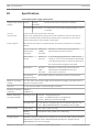
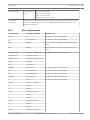
20
Specifications
144
20.1
Wire requirements
145
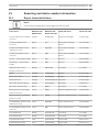
21
Reporting and device number information
147
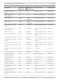
21.1
Report format definitions
147
21.2
SDI2 address information
155
21.3
Device numbers (zzz, dddd)
155
21.4
Communication Trouble device numbers (zzzz)
156
21.5
Special User IDs (uuuu, iiii)
156
21.6
Keypad alarm virtual point numbers (ppp, pppp)
156
Bosch Security Systems, Inc.
Installation and System Reference Guide
2014.05 | 11 | F.01U.287.180
8
en | Certifications, approvals, listings, and safety
Control Panel
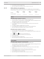
1
Certifications, approvals, listings, and safety
1.1
Certifications and approvals
This document includes the section Approved applications, page 91. Refer to this section for
guidelines on installing the control panels in Underwriters Laboratories Inc. (UL) and firespecific applications.
1.2
Listings and approvals
1.2.1
UL
Listed for:
1.2.2
–
UL 365 - Police Station Connected Burglar Alarm Units and System
–
UL 609 - Local Burglar Alarm Units and System
–
UL 636 - Holdup Alarm Units and System
–
UL 985 - Household Fire Warning System Units
–
UL 1023 - Household Burglar Alarm Units and System
–
UL 1076 - Proprietary Burglar Alarm Units and System
–
UL 1610 - Central Station Burglar Alarm Units
–
UL 1635 - Digital Alarm Communicator System Units
–
UL 2017 - General-Purpose Signaling Devices and Systems
ULC
Listed for:
1.2.3
–
ULC C1023 - Household Burglar Alarm System Units
–
ULC C1076 - Proprietary Burglar Alarm Units and System
–
ULC S303 - Local Burglar Alarm Units and System
–
ULC S304 - Central and Monitoring Station Burglar Alarm Units
–
ULC S545 - Residential Fire Warning System Control Units
Security Industry Association (SIA)
Listed for Control Panel Standard - Features for False Alarm Reduction ANSI/SIA CP-01-2010.
1.2.4
Department of Defense (DoD)
The B5512/B4512/B3512 control panels were granted approval for Department of Defense
(DoD) installations in Sensitive Compartmented Information Facilities (SCIF).
1.2.5
California State Fire Marshal (CSFM)
Listed for Household Fire Alarm.
1.2.6
National Institute of Standards and Technology (NIST)
When communicating via a network, listed for Advanced Encryption Standard (AES), Federal
Information Processing Standards Publication 197 (FIPS 197).
1.2.7
Federal Communications Commission (FCC) Rules
Part 15
This equipment was tested and found to comply with the limits for a Class A digital device,
pursuant to Part 15 of the FCC rules. These limits are designed to provide reasonable
protection against harmful interference when the equipment is operated in a commercial
environment.
2014.05 | 11 | F.01U.287.180
Installation and System Reference Guide
Bosch Security Systems, Inc.
Control Panel
Certifications, approvals, listings, and safety | en
9
This equipment generates, uses, and can radiate radio frequency energy; and if not installed
and used according to the instructions, can cause harmful interference to radio
communications.
Operation of this equipment in a residential area is likely to cause harmful interference, in
which case the user is required to correct the interference at his or her own expense.
Part 68
The B430 module by Bosch Security Systems, Inc. is registered with the Federal
Communication Commission (FCC) under Part 68, for connection to the public telephone
system using an RJ31X or RJ38X phone line connection jack installed by the local telephone
company.
Do not connect registered equipment to party lines or coin-operated telephones. Notify the
local telephone company and provide the following information before connecting the control
panel to the telephone network:
–
The particular line to which you connect the module
–
Make (Bosch Security Systems, Inc.), model (B5512/B4512/B3512), and serial number of
the control panel
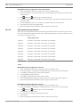
1.2.8
–
FCC registration number: ESVAL00BB430
–
Ringer eq: 0.0B
Industry Canada (IC)
ICES-003 - Information Technology Equipment
This Class A digital equipment meets all requirements of the Canadian interference-causing
equipment regulations.
Cet appareil numérique de la Class A respecte toutes les exifences de règlement sue le
matériel brouilleur du Canada.
CS-03 - Compliance Specification for Terminal Equipment
This product meets the applicable Industry Canada technical specifications. The Ringer
Equivalence Number (REN) is an indication of the maximum number of devices allowed to be
connected to a telephone interface. The termination of an interface may consist of any
combination of devices subject only to the requirement that the sum of the RENs of all the
devices not exceed five.
Le présent matériel est conforme aux specifications techniques applicables d'Industrie
Canada.
L'indice d'équivalence de la sonnerie (IES) sert à indiquer le nombre maximal de terminaux qui
peuvent être raccordés à une interface téléphonique. La terminaison d'une interface peut
consister en une combinaison quelconque de dispositifs, à la seule condition que la somme
d'indices d'équivalence de la sonnerie de tous les dispositifs n'excède pas cinq.
1.3
Lightning
The B5512/B4512/B3512 control panels design significantly reduces the adverse effects of
lightning. Taking installation precautions can further reduce these adverse effects.
1.3.1
Effects
Lightning can directly strike any electronic system, or lightning strikes near a system can
adversely affect the system. When lightning strikes, several things happen:
–
An electromagnetic wave spreads from the point of the strike inducing high voltages in
nearby conductors.
–
The voltage changes substantially on electrical grounds near the lightning strike.
–
High voltages are induced in anything directly struck by lightning.
The effects of lightning can include trouble events, alarm events, and physical damage.
Bosch Security Systems, Inc.
Installation and System Reference Guide
2014.05 | 11 | F.01U.287.180
10
en | Certifications, approvals, listings, and safety
1.3.2
Control Panel
Installation precautions
To minimize the undesirable effects from lightning:
–
Do not run wiring outside the building.
–
If you install the unit in a metal building, keep the wiring at least 2 ft (0.61 m) away from
external metal surfaces. Make a proper earth ground connection.
–
Earth ground the unit correctly. Do not use an electrical ground or telephone ground.
–
Avoid running wires near telephone, data, or power lines. Locating control panel wiring at
least 2 ft (0.61 m) away helps reduce the effects of lightning.
–
When your data lines must cross the path of AC or other wiring, cross the lines
perpendicularly.
2014.05 | 11 | F.01U.287.180
Installation and System Reference Guide
Bosch Security Systems, Inc.
Control Panel
Introduction | en
2
Introduction
2.1
About documentation
11
This document contains instructions for a trained installer to properly install, configure, and
operate this control panel, and optional peripheral devices. Review this document before
beginning the installation to determine the hardware and wiring requirements for the features
used.
(Bosch security Systems, Inc. recommends that installers follow good wiring practices such as
those descibed in NFPA 731, Standard for the Installation of Electronics Premises Security
Systems.)
Throughout this document, the words “control panel” refer to all control panels covered by
this document (B5512/B5512E/B4512/B4512E/B3512/B3512E).
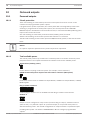
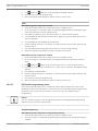
Notifications
This document uses Notices, Cautions, and Warnings to draw your attention to important
information.
Notice!
These include important notes for successful operation and programming of equipment, or
indicate a risk of damage to the equipment or environment.
Caution!
!
These indicate a hazardous situation which, if not avoided, could result in minor or moderate
injury.
Warning!
!
These indicate a hazardous situation which, if not avoided, could result in death or serious
injury.
Copyright
This document is the intellectual property of Bosch Security Systems, Inc. and is protected by
copyright. All rights reserved.
Trademarks
All hardware and software product names used in this document are likely to be registered
trademarks and must be treated accordingly.
2.1.1
Related documentation
To obtain any of the documents listed in this section, download them from the web.
Downloading documentation:
1.
Go to the Bosch website (us.boschsecurity.com).
2.
In the Search text box on the right side of the page, enter the CTN for the product for
which you wish to download the documentation.
3.
Press [ENTER].
4.
If you see the desired document in the search results, click the link for the document to
open it. Otherwise, click the desired product’s Product Page button. The product page
opens with the Details tab selected.
Bosch Security Systems, Inc.
Installation and System Reference Guide
2014.05 | 11 | F.01U.287.180
12
en | Introduction
Control Panel
5.
Click on the Documents tab, and then click the desired language listed to the right of the
desired document.
Call Bosch Security Systems, Inc., Technical Support (1-800-289-0096) if you need additional
assistance.
Control panel documents
Control Panels (B5512/B4512/B3512) Release Notes (P/N: F01U299696)*
Control Panels (B5512/B4512/B3512) Installation and System Reference Guide (this document)
(P/N: F01U287180)+
Control Panels (B5512/B4512/B3512) Owner’s Manual (P/N: F01U287181)*
+
Control Panels (B5512/B4512/B3512) Program Entry Guide (P/N: F01U287183)+
Control Panels (B5512/B4512/B3512) UL Installation Guide (P/N: F01U287185)*
+
Control Panels (B5512/B4512/B3512) SIA Quick Reference Guide (P/N: F01U287184)*
+
*Shipped with the control panel. +Located on the documentation CD shipped with the
control panel.
Keypad documents
Basic Keypad (B915) Installation Guide (P/N: F01U297873)*
Two-line Alphanumeric Keypad (B920) Installation Guide (P/N: F01U265450)*
Two-line Capacitive Keypad with Inputs (B921C) Installation Guide (P/N: F01U285416)*
ATM Style Alphanumeric Keypad (B930) Installation Guide (P/N: F01U265451)*
Touch Screen Keypad (B942/B942W) Installation Guide (P/N: F01U294527)*
*Shipped with the keypad.
Optional module documents
2-wire Powered Loop Module (B201) Installation and Operation Guide (P/N: F01U301248)*
Octo-input Module (B208) Installation and Operation Guide (P/N: F01U265456)*
Octo-output Module (B308) Installation and Operation Guide (P/N: F01U265458)*
Conettix Ethernet Communication Module (B426) Installation and Operation Guide (P/N:
F01U281208)*
+
Plug-in Telephone Communicator (B430) Installation Guide Installation Guide (P/N:
F01U265454)*
Conettix Plug-in Cellular Communicator (B440) Installation and Operation Guide (P/N:
F01U265455)*
Conettix Plug-in CDMA Cellular Communicator (B441) Installation and Operation Guide (P/N:
F01U282233)*
Conettix Plug-in GPRS Cellular Communicator (B442) Installation and Operation Guide (P/N:
F01U283180)*
Conettix Plug-in HSPA+ Cellular Communicator (B443) Installation and Operation Guide (P/N:
F01U283181)*
2014.05 | 11 | F.01U.287.180
Installation and System Reference Guide
Bosch Security Systems, Inc.
Control Panel
Introduction | en
13
Conettix Plug-in Communicator Interface (B450) Installation and Operation Guide (P/N:
F01U300740)*
+
Auxiliary Power Supply (B520) Installation and Operation Guide (P/N: F01U265445)*
RADION receiver SD (B810) Installation Guide (P/N: F01U261834)*
SDI2 Inovonics Interface Module (B820) Installation Guide (P/N: F01U265460)*
*Shipped with the module. +Located on the documentation CD shipped with the module.
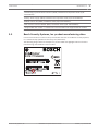
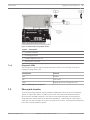
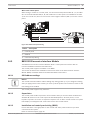
2.2
Bosch Security Systems, Inc. product manufacturing dates
Use the serial number located on the product label and refer to the Bosch Security Systems,
Inc. website at http://www.boschsecurity.com/datecodes/.
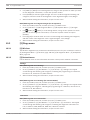
The following image shows an example of a product label and highlights where to find the
manufacturing date within the serial number.
Bosch Security Systems, Inc.
Installation and System Reference Guide
2014.05 | 11 | F.01U.287.180
14
3
en | System overview
Control Panel
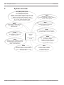
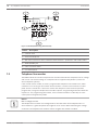
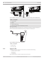
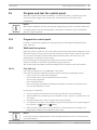
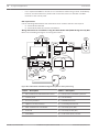
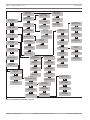
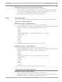
System overview
B91x/B92x/B93x/B94x
Use keypads to operate
the control panel by area.
B5512 control panels support up to 4 areas.
B4512 control panels support up to 2 areas.
B3512 control panels support 1 area.
Each area can have its own account number
or you can group together areas
with a common account number.
B820
SDI2 Inovonics Interface modules
interface with an Inovonics
wireless receiver.
B208
Octo-input modules allow
the addition of up to 8
input devices.
B308
Octo-output modules allow
the addition of up to 8
output devices.
B520
Auxiliary Power Supply modules
expand power by connecting to
an SDI2 device bus or
other 12 volt devices.
B426
The B426 provides off-board
communication over a network.
Control
Panel
B430
Plug-in Tephone Communicator
provides a single
telephone RJ-45 connector
to allow communication
over telephone lines.
On-board Points
1 to 8
B450
Conettix Plug-In Communicator
Interface allows communciation
over a cellular network through
the SDI2 bus.
2014.05 | 11 | F.01U.287.180
B810
RADION receiver SDs
connect RADION wireless devices
to the control panel.
B44x
Conettix Plug-In Cellular
Communicator allows
communciation over
a cellular network.
Installation and System Reference Guide
Bosch Security Systems, Inc.
Control Panel
System overview | en
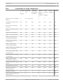
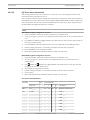
3.1
Configuration and parts
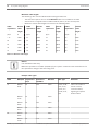
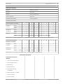
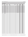
3.1.1
Control panel capacities
Features
B5512
B4512
B3512
Number of users
50
32
10
Number of custom functions
4
2
1
Number of areas
4
2
1
Number of points
48
28
16
Number of outputs
43
27
3
Number of keypads
8
8
4
Number of B208 Octo-input Modules
4
2
0
Number of B308 Octo-output Modules
5
3
0
Number of on-board Ethernet ports (E control panel variants do not
1
1
1
1
1
1
Number of B430 Plug-in Telephone Communicators or B440 Conettix Plug- 1
1
1
15
include an Ethernet port)
Number of B426 Conettix Ethernet Communication Modules or B450
Conettix Plug-in Communicator Interfaces
in Cellular Communicators or B441 Conettix Plug-in CDMA Cellular
Communicators or B442 Plug-in GPRS Cellular Communicator or B443
Plug-in HSPA+ Cellular Communicator
Number of B520 Auxiliary Power Supply Modules
4
2
2
Number of RADION receiver SDs (B810) or B820 SDI2 Inovonics Interface
1
1
1
Modules
3.1.2
Parts list
Control panels ship assembled from the factory with the following parts:
Literature
–
Control Panels (B5512/B4512/B3512) UL Installation Guide
–
Control Panels (B5512/B4512/B3512) Owner’s Manual
–
Control Panels (B5512/B4512/B3512) SIA Quick Reference Guide
–
Control Panels (B5512/B4512/B3512) Documentation CD
–
Enclosure Wiring Label (B5512/B4512/B3512)
HW pack
Mounting clips
–
–
EOL resistors
–
Battery wires
–
Four #6 x 3/4 in self threading screws
Assembly
–
PC board
Bosch Security Systems, Inc.
Installation and System Reference Guide
2014.05 | 11 | F.01U.287.180
16
en | System overview
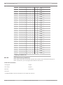
3.1.3
Control Panel
Order separately
Order the accessories listed below to aid in the installation of your control panel. If you
ordered your control panel in a kit, you might already have these parts.
–
B91x/B92x/B93x/B94x keypad
–
18VAC, 22VA approved plug-in transformer
–
D126 or D1218 Battery
–
B430 Plug-in Telephone Communicator or a B440 Conettix Plug-in Cellular
Communicator/B441 Conettix Plug-in CDMA Cellular Communicator/B442 Plug-in GPRS
Cellular Communicator/B443 Plug-in HSPA+ Cellular Communicator
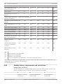
3.2
–
D161 or D162 Phone Cord
–
B10 Medium Control Panel Enclosure or B11 Small Control Panel Enclosure
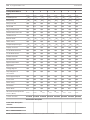
Accessories
Compatible accessories
CTN
Name
UL 985
Intrusion
cUL
Fire
B10
Medium Control Panel Enclosure
x
x
x
B11
Small Control Panel Enclosure
x
x
x
B12
Mounting Plate for D8103 Enclosure
B201
2-wire Powered Loop Module1
X
X
x
B208
Octo-input Module
x
x
x
B308
Octo-output Module
x
x
x
B426
Conettix Ethernet Communication Module
x
x
x
B430
Plug-in Telephone Communicator
x
x
x
B440
Conettix Plug-in Cellular Communicator
x
x
B441
Conettix Plug-in CDMA Cellular Communicator
x
x
B450
Conettix Plug-in Communicator Interface
x
x
x
B520
Auxiliary Power Supply Module
x
x
x
B810
RADION receiver SD2
x
x
B820
SDI2 Inovonics Interface Module3
x
x
B915
Basic Keypad
x
x
x
B920
Two-line Alphanumeric Keypad (SDI2)
x
x
x
B921C
Two-line Capacitive Keypad with Inputs (SDI2) (B921CW
x
x
x
x
x
x
white)4
B930
ATM Style Alphanumeric Keypad (SDI2)
B942
Touch Screen Keypad (B942W white)
CX4010
UL Listed Class 2 Transformer 18 VAC 22 VA 60 Hz
x
x
D125B
Dual Class B Initiating Module5
x
x
2014.05 | 11 | F.01U.287.180
Installation and System Reference Guide
x
Bosch Security Systems, Inc.
Control Panel
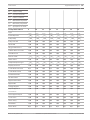
CTN
System overview | en
Name
UL 985
Intrusion
cUL
x
x
17
Fire
D126
Battery (12.0 VDC, 7 Ah)
D1218
Battery (12 V, 18 Ah)
D161
Phone Cord
D162
Phone Cord
D130
Auxiliary Relay Module
x
D132A
Smoke Detector Reversing Relay Module
x
D133
Single Relay Module
x
x
D134
Dual Relay Module
x
x
FCC-380
Carbon Monoxide Detector (example of UL listed device,
x
other UL listed devices are available)
F220-P with
Photoelectric Smoke Detector with Detector Base (example of x
F220‑B6
UL listed detector, other UL listed detectors are available)
HUB
Potter HUB Holdup Button (example of UL listed holdup
x
device, other UL listed devices are available)
ICP-EZTS
Tamper Switch
x
ICP-TR1822-CAN
Plug-in Transformer 120 VAC primary, 18 VAC 22 VA secondary
ISC-BDL2-WP12
Blue Line Gen2 Pet Friendly TriTech Motion Detector
x
x
x
x
x
(example of UL listed detector, other UL listed devices are
available)
MB-G6-12-R
Wheelock MB Series 12V 6 " Fire Bell (Red) (example of UL
x
listed device, other UL listed devices are available)
5110/4001-42
Rothenbuhler High Security Bell
x
Latin America:
B442
Plug-in GPRS Cellular Communicator
x
x
x
Plug-in HSPA+ Cellular Communicator
x
x
x
Canada:
B443
1
Refer to the 2-wire Powered loop Module (B201) Installation Guide (P/N: F01U296412) for compatible B201
devices.
2
Refer to the section within this section for compatible RADION devices.
3
Refer to the section within this section for compatible Inovonics devices.
4
Only ULC listed for Proprietary Burglary and Residential Fire.
5
Refer to the Dual Class B Inititating Module (D125B) Installation Instructions (P/N: F01U036340) for compatible
D125B devices.
Bosch Security Systems, Inc.
Installation and System Reference Guide
2014.05 | 11 | F.01U.287.180
18
en | System overview
Control Panel
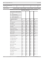
B810 wireless receiver compatible accessories
Refer to RADION receiver SD (B810) Installation Guide.
Model
Name
Description
RFBT-A
RADION specialty
Bill trap
RFDL-11-A
RADION TriTech
Motion detector
RFDW-RM-A
RADION contact RM
Door/window contact
RFDW-SM-A
RADION contact SM
Recessed door/window contact
RFGB-A
RADION glassbreak
Glassbreak detector
RFIN-A
RADION inertia1
Intertia detector
RFKF-FB-A
RADION keyfob FB
Four-button keyfob
RFKF-TB-A
RADION keyfob TB
Two-button keyfob
RFPB-SB-A
RADION panic SB
Single button panic
RFPB-TB-A
RADION panic TB
Two button panic
RFRP-A
RADION repeater
Repeater
RFSM-A
RADION smoke2
Smoke detector
RFPR-12-A
RADION PIR
PIR detector
RFPR-C12-A
RADION PIR C
PIR curtain detector
RFUN-A
RADION universal
Universal transmitter
1
Not investigated by UL.
2
UL 985 only.
2014.05 | 11 | F.01U.287.180
Installation and System Reference Guide
Bosch Security Systems, Inc.
Control Panel
System overview | en
19
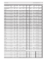
B820 SDI2 Inovonics Interface Module compatible accessories
Model
Name
EN1210
Universal Transmitter (Single-input)
EN1210EOL
Universal Transmitter with EOL Resistor
EN1210W
Door-Window Transmitter with Reed Switch
EN1215EOL
Universal Transmitter with Wall Tamper and EOL Resistor
EN1215WEOL
Door-Window Transmitter with Wall Tamper, Reed Switch, and EOL Resistor
EN1223D
Water-resistant Pendant Transmitter (Double-button)
EN1223S
Water-resistant Pendant Transmitter (Single-button)
EN1224-ON
Multiple-Condition Pendant Transmitter
EN1233D
Necklace Pendant Transmitter (Double-button)
EN1233S
Necklace Pendant Transmitter (Single-button)
EN1235D
Beltclip Pendant Transmitter (Double-button)
EN1235DF
Fixed-location Transmitter (Double-button)
EN1235S
Beltclip Pendant Transmitter (Single-button)
EN1235SF
Fixed-location Transmitter (Single-button)
EN1242
Smoke Detector Transmitter
EN1247
Glass-break Detector Transmitter
EN1249
Bill Trap Transmitter
EN1260
Wall Mount Motion Detector
EN1261HT
High Traffic Motion Detector
EN1262
Motion Detector With Pet Immunity
EN1265
360° Ceiling Mount Motion Detector
EN4200
Serial Receiver
EN4204R
Four Zone Add-on Receiver With Relay Outputs
EN5040-T
High Power Repeater With Transformer
EN7016
Wireless Survey Kit
ENKIT-SDI2
B820 and EN4200 Kit
Notice!
No wireless detectors have been approved for use with alarm verification points.
For specific installation and operation instructions, please refer to manufacturers' manuals.
Bosch Security Systems, Inc.
Installation and System Reference Guide
2014.05 | 11 | F.01U.287.180
20
en | System overview
Control Panel
3.3
Features
3.3.1
SDI2 interconnect wiring
Most SDI2 modules include one or two interconnect wiring connectors. You can use these
connectors to connect the modules to the control panel, and then to each other, without
having to connect wires individually to the SDI2 terminals. For installations using multiple
SDI2 modules in the same enclosure, interconnect wiring makes the installation quicker and
easier than using terminal strip wiring. Each SDI2 module that has an SDI2 interconnect wiring
connector comes with a 12 in (30 cm) interconnect cable.
3.3.2
Points
B5512 control panels provide up to 48 points of protection. B4512 control panels provide up
to 28 points of protection. B3512 control panels provide up to 16 points of protection. Point
programming parameters determine the control panel’s response to open and shorted
conditions on the sensor loop for the point. Several options allow individual point
programming to custom-fit the protection to the installation.
The control panel has eight on-board points, points 1 to 8.
The SDI2 bus allows for the remaining off-board points. For example, the SDI2 bus supports a
combination of B208 Octo-input Modules, and a B810 wireless receiver.
Caution!
!
3.3.3
Any points programmed as fire supervisory points are latching. A latching point requires
acknowledgment before it can be cleared.
Areas and accounts
B5512 control panels support up to 4 areas. B4512 control panels support up to 2 areas.
B3512 control panels support 1 area. You can assign all points to a single area or distribute
them over multiple areas.
Users can turn areas on and off individually or together. You can assign an authority level to a
user that allows the user to turn an area on from a remote keypad in another area.
Assigning each area its own account number creates up to 4 separate accounts in the B5512,
and up to 2 separate accounts in the B4512. Assigning the same account number to different
areas groups them together in a single account.
Area options include exit tone and delay, separate fire and burglary outputs, and multiple
opening and closing windows. Use area types to create area relationships.
For systems with more than one area, all areas must be under the responsibility of one
ownership and management. This may be a group of buildings attached or unattached and
may even have different addresses but are under the responsibility of someone having mutual
interest (other than the alarm installing company). This does not apply to strip mall
applications where each independent business must have their own separate alarm system.
An example for a commercial system would be a business that has an OFFICE area and a
WAREHOUSE area in a building where each area can be armed or disarmed independently.
As a residential example a system could be configured with the garage and house as separate
areas.
In each of the examples above all of the areas are under the sole responsibility of a single
owner.
In multi-area systems the bell (or siren) and control panel must be in one of the protected
areas.
2014.05 | 11 | F.01U.287.180
Installation and System Reference Guide
Bosch Security Systems, Inc.
Control Panel
System overview | en
21
The bell or siren must be located where it can be heard by users who turn areas on and off
(arm and disarm).
3.3.4
Digital communication
The control panel uses its built-in Ethernet connection, a B426 Conettix Ethernet
Communication Module, a Conettix Plug-in cellular module (B440/B441/B442/B443 plugged
into the control panel or plugged into a B450 Conettix Plug-in Communicator Interface), or a
B430 Plug-in Telephone Communicator to send reports to the central station receiver.
The control panel sends reports in either the Modem4 or ANSI-SIA Contact ID format.
The system can route Event Reports to four different destinations through an IP network or
the telephone network (PSTN). Primary and backup reporting paths can be programmed for
each destination. A custom option allows you to specify which Event Reports the system
sends.
3.3.5
Keypads
The control panels support up to 8 keypads on the SDI2 bus. Use any combination of B Series
keypads. The control panel supervises all keypads.
3.3.6
Event memory
The control panel retains point alarm and trouble events for each area in event memory. You
can view event memory on a keypad. Turning an area on clears the event memory for that area.
3.3.7
Event log
The event log stores up to 255 local and reported events. The event log includes time, date,
event, area, point, and user. View the event log from a keypad or use RPS to remotely retrieve
event information. When the event log reaches a programmed threshold of stored events, it
can send an optional report to a receiver.
Notice!
B5512 control panels store up to 255 events. B4512 and B3512 control panels store up to
127.
3.3.8
Programming
Use RPS to program the control panels. You can connect to the control panel using a network
connection (on-board Ethernet port, cellular module, B426 Conettix Ethernet Communication
Module, or telephone module), or locally using the control panel’s on-board Ethernet port or
USB port. (To program with the USB port connection, use the B99 USB 2.0 Type A Male to
Type A Male cable by Bosch.) You can also use a keypad for select programming.
Refer to RPS Help or the control panel's Program Entry Guide, and to Keypad Installer menu,
page 103 for programming options.
Notice!
After system installation and any control panel programming, perform a complete system test.
A complete system test includes testing the control panel, all devices, and communication
paths for proper operation.
Bosch Security Systems, Inc.
Installation and System Reference Guide
2014.05 | 11 | F.01U.287.180
22
en | System overview
3.3.9
Control Panel
Firmware updates
Firmware updates
Remote firmware updates through Remote Programming Software (RPS) using the RPS
Firmware Update Wizard. The Firmware Update Wizard uses the on-board USB connection or
optional IP connection (on-board Ethernet connection, B426 Conettix Ethernet
Communication Module, B440 Conettix Plug-in Cellular Communicator, B441 Conettix Plug-in
CDMA Cellular Communicator, B442 Plug-in GPRS Cellular Communicator (Latin America),
B443 Plug-in HSPA+ Cellular Communicator (Canada)) to transmit the updates.
–
Control panel updates. Remotely update the control panel firmware for easy feature
enhancements without replacing ROM chips.
–
Module update support. Remotely update the firmware on connected SDI2 modules for
easy feature enhancements without visiting each individual module.
2014.05 | 11 | F.01U.287.180
Installation and System Reference Guide
Bosch Security Systems, Inc.
Control Panel
4
Installation workflow | en
23
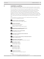
Installation workflow
Before installing and operating the control panel, read these instructions. Failure to follow
these procedures may cause the device not to function properly. Bosch Security Systems Inc.
is not responsible for any devices that are improperly installed, tested, or maintained.
This document does not contain special information about local requirements and safety
issues. Information on such issues is provided only to the extent that it is needed for
operation of the device. Ensure that you are familiar with all safety-related processes and
regulations in your area. This also includes how to act in the event of an alarm and the initial
steps to take if a fire breaks out. The operating instructions should always be available on site.
It is a required part of the system and must be given to the new owner if the system is ever
sold.
Use the workflow and checkboxes below as you complete steps. Each step includes
references for more detailed information.
–
Install the enclosure and wiring label
Install the enclosure and wiring label, page 25
–
Install the control panel
Mount the control panel, page 25
–
Connect earth ground, page 27
–
Configure OUTPUT A using the jumper, page 27
–
Install and wire for telephone communication
Telephone communications, page 38
–
Install and wire for IP communications
IP communications, page 42
–
Install and wire the battery and the transformer
Power supply, page 30
–
Begin to charge the battery while you install other devices
Charge the battery, page 32
–
Install and wire arming devices
Keypads, keyswitches, keyfobs and transmitters, page 54
–
Install and wire outputs
On-board outputs, page 60
–
Off-board outputs, page 62
–
Install and wire inputs
On-board points, page 65
–
Off-board points, page 67
–
Wireless modules, page 72
–
Complete the installation
Program and test the control panel, page 75
See also
–
Bosch Security Systems, Inc.
Keypads, keyswitches, keyfobs and transmitters, page 54
Installation and System Reference Guide
2014.05 | 11 | F.01U.287.180
24
en | Installation workflow
Control Panel
–
Mount the control panel, page 25
–
Install the enclosure and wiring label, page 25
–
Power supply, page 30
–
Telephone communications, page 38
–
IP communications, page 42
–
On-board points, page 65
–
Off-board points, page 67
–
Off-board outputs, page 62
–
Wireless modules, page 72
–
Program and test the control panel, page 75
–
On-board outputs, page 60
–
Configure OUTPUT A using the jumper, page 27
–
Connect earth ground, page 27
–
Install the battery, page 32
2014.05 | 11 | F.01U.287.180
Installation and System Reference Guide
Bosch Security Systems, Inc.
Control Panel
Control panel installation | en
5
Control panel installation
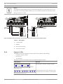
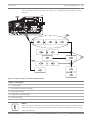
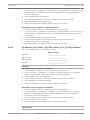
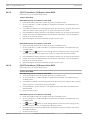
5.1
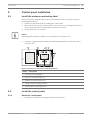
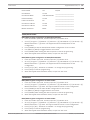
Install the enclosure and wiring label
25
Refer to Enclosures, page 96 to determine if the application requires a specific enclosure.
Installing the enclosure:
1.
Remove any knockouts prior to installing the control panel.
2.
Mount the enclosure in the desired location. Use all enclosure mounting holes. Refer to
the mounting instructions supplied with the selected enclosure.
3.
Pull the wires into the enclosure.
Notice!
Electromagnetic interference (EMI) can cause problems on long wire runs.
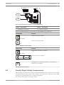
4.
Install the supplied Enclosure Wiring Label (B5512/B4512/B3512) on the inside of the
enclosure door.
1
2
3
2
3
4
2
5
2
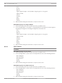
Figure 5.1: Enclosure and control panel mounting (B10 shown)
Callout ᅳ Description
1 ᅳ Control panel wiring label
2 ᅳ Enclosure mounting holes (4)
3 ᅳ Module mounting locations (4)
4 ᅳ Tamper switch mounting location
5 ᅳ Control panel mounting location
5.2
5.2.1
Install the control panel
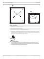
Mount the control panel
1.
Bosch Security Systems, Inc.
Identify the control panel mounting location in the enclosure.
Installation and System Reference Guide
2014.05 | 11 | F.01U.287.180
26
en | Control panel installation
Control Panel
Figure 5.2: B10 and B11 control panel placement locations
Callout ᅳ Description
1 ᅳ B10 Medium Control Panel Enclosure
2 ᅳ B11 Small Control Panel Enclosure
3 ᅳ Mounting clip locations for the B5512/B4512/B3512
2.
Snap the four supplied plastic standoffs onto four enclosure support posts. If using the
B12 Mounting Plate for D8103 Enclosure, attach the standoffs to the plate support posts.
Do not attach the standoffs with screws at this time.
Figure 5.3: Standoff attachment
3.
Place the control panel on top of the standoffs. Align the holes in the corners of the
control panel with the openings at the top of each standoff. Secure the control panel to
the standoffs with supplied, self-threading screws.
2014.05 | 11 | F.01U.287.180
Installation and System Reference Guide
Bosch Security Systems, Inc.
Control Panel
Control panel installation | en
27
Figure 5.4: Mount control panel on standoffs
4.
If using the B12 Mounting Plate for D8103 Enclosure, rest the hook tabs on the mounting
plate hooks within the enclosure. Secure the lock-down tab to the plate mounting hole
with the screw provided.
5.2.2
Connect earth ground
To help prevent damage from electrostatic discharges or other transient electrical surges,
connect the system to earth ground at the earth ground terminal before making other
connections. The
icon (Terminal 10) indicates the earth ground terminal. Use a
recommended earth ground reference, such as a grounding rod or a cold water pipe.
Notice!
Do not use telephone or electrical ground for the earth ground connection. Use 14 AWG (1.8
mm) to 16 AWG (1.5 mm) wire when making the connection. Do not connect other control
panel terminals to earth ground.
Caution!
!
5.2.3
Avoid electrostatic discharge. Always touch the earth ground connection with the
icon first,
before beginning work on the control panel.
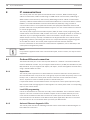
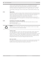
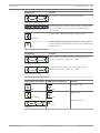
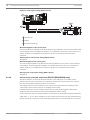
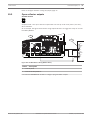
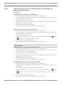
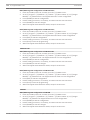
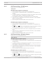
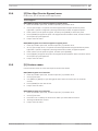
Configure OUTPUT A using the jumper
When planning your installation, carefully consider the use of OUTPUT A. OUTPUT A is a form
C relay. You can configure the common terminal (C) of Output A (OUTPUT A) using the
jumper:
–
To provide +12 VDC (AUX power)
–
To be a COM terminal (parallel to all COM terminals)
–
To be a dry contact (no voltage, not common)
The control panel ships with the jumper in the default position, AUX power. (OUTPUT A, ‘C’
terminal using AUX PWR). Remove the door covering the jumper pins, and then move the
jumper to the left two pins for switched low (OUTPUT A parallel to COM terminals). Replace
the cover door. The OUTPUT A LED lights when OUTPUT A is active. Refer to the figure below
or to the Enclosure Wiring Label (B5512/B4512/B3512) to set the OUTPUT A jumper.
Bosch Security Systems, Inc.
Installation and System Reference Guide
2014.05 | 11 | F.01U.287.180
28
en | Control panel installation
Control Panel
OUTPUT A (C terminal) = AUX PWR
P1
COM AUX
OUTPUT A (C terminal) = COM
P1
COM AUX
OUTPUT A (C terminal) = DRY
P1
COM AUX
COMMUNICATION MODULE 1
ETHERNET
ETHERNET
100BASE-T
LINK
USB
RESET
P1
ON-BOARD POINTS
Voltage Ranges
Open
3.7 - 5.0 VDC
Normal 2.0 - 3.0 VDC
Short
0.0 - 1.3 VDC
1k
AUX
OUTPUT A - 12 V +
18 VAC
18VAC
NO C NC COM AUX R Y
PWR A
OUTPUT A
+ BAT -
G B
B COM
C
OUTPUT
B
End of Line Resistors
1 COM 2 3 COM 4
5 COM 6
7 COM 8
1
5
7
COM
2
3
COM
4
COM
6
COM
TMPR
SDI2
Device Bus
R Y G B
C
B
OUTPUT
COM AUX
8
Figure 5.5: OUTPUT A jumper configuration options (B5512 shown)
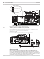
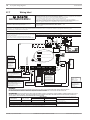
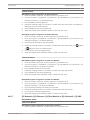
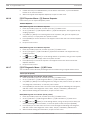
5.3
Control panel to module wiring overview
In the following sections, this document provides instructions for wiring devices to your
control panel. You can use interconnect or terminal wiring.
Using terminal wiring
For terminal wiring, use 18 AWG to 22 AWG (1.02 mm to 0.65 mm) wire.
COMMUNICATION MODULE 1
ETHERNET
ETHERNET
100BASE-T
LINK
OUTPUT A
Jumper Under Cover
ON-BOARD POINTS
Voltage Ranges
Open
3.7 - 5.0 VDC
Normal 2.0 - 3.0 VDC
Short
0.0 - 1.3 VDC
1k
18 VAC
18VAC
BATTERY
+ BAT -
AUX
OUTPUT A - 12 V +
NO C NC COM AUX R Y
PWR A
OUTPUT A
G B
B COM
RESET
SDI2
Device Bus
R Y G B
C
OUTPUT
B
End of Line Resistors
1 COM 2 3 COM 4
5 COM 6
7 COM 8
1
5
7
COM
2
3
COM
4
COM
6
COM
C
B
OUTPUT
OUTPUT A
USB
TMPR
AUX PWR
COM
DRY
8
PWR
A
B
COM
PWR
A
B
COM
Figure 5.6: SDI2 devices daisy chained with terminal wiring (B5512 shown)
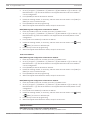
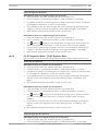
Using interconnect wiring
Interconnect wiring connectors parallel the SDI2 PWR, A, B, and COM terminals on the
terminal strip. In installations with multiple SDI2 modules, using interconnect wiring makes
the installation quicker and easier than using terminal strip wiring. You use any combination of
terminal and interconnect wiring to wire multiple modules in parallel, but do not wire a single
module to the control panel using both terminal and interconnect wiring.
2014.05 | 11 | F.01U.287.180
Installation and System Reference Guide
Bosch Security Systems, Inc.
Control Panel
Control panel installation | en
29
The interconnect wiring connectors are "keyed" (interconnect wiring plug can fit in only one
direction).
COMMUNICATION MODULE 1
ETHERNET
ETHERNET
100BASE-T
LINK
OUTPUT A
Jumper Under Cover
ON-BOARD POINTS
Voltage Ranges
Open
3.7 - 5.0 VDC
Normal 2.0 - 3.0 VDC
Short
0.0 - 1.3 VDC
1k
18 VAC
18VAC
BATTERY
+ BAT -
AUX
OUTPUT A - 12 V +
NO C NC COM AUX R Y
PWR A
OUTPUT A
G B
B COM
RESET
SDI2
Device Bus
R Y G B
C
OUTPUT
B
End of Line Resistors
1 COM 2 3 COM 4
5 COM 6
7 COM 8
1
5
7
COM
2
3
COM
4
COM
6
COM
C
B
OUTPUT
OUTPUT A
USB
TMPR
AUX PWR
COM
DRY
8
PWR
A
B
COM
PWR
A
B
COM
Figure 5.7: SDI2 devices daisy chained with interconnect wiring (B5512 shown)
Bosch Security Systems, Inc.
Installation and System Reference Guide
2014.05 | 11 | F.01U.287.180
30
en | Power supply
Control Panel
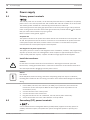
6
Power supply
6.1
Primary power terminals
The control panel uses an 18 VAC, 22 VA internally fused transformer (CX4010) for its primary
power source. The control panel draws 125 mA when idle and 155 mA when in an alarm state.
The auxiliary power available for continuously powered devices is 800 mA.
Transient suppressors and spark gaps protect the circuit from power surges. This protection
relies on the ground connection at the earth ground terminal, marked with the
icon. Ensure
that you connect the terminal to a proper ground.
Refer to Connect earth ground, page 27.
AC power fail
The system indicates an AC power failure when the 18 VAC terminals do not have power. The
AC Fail Time parameter sets the number of minutes or seconds without AC power before the
control panel reports the failure, and the number of minutes or seconds after the power
returns before the control panel reports restored power.
Self diagnostics at power up and reset
The system performs a series of self-diagnostic tests of hardware, software, and programming
at power up and at reset. The self-diagnostics tests complete in approximately 10 to 30 sec.
If the control panel fails any test, a System Trouble message appears at the keypads.
6.1.1
Install the transformer
Caution!
!
Do not short-circuit the terminals of the transformer: Shorting the terminals opens the
internal fuse, causing permanent failure. Connect the transformer to the 18 VAC terminals of
the control panel before plugging it into the power source.
Notice!
Plan ahead
Route telephone, SDI2 bus wiring, and sensor loop wiring away from any AC conductors,
including the transformer wire. AC wiring can induce noise and low level voltage into adjacent
wiring.
1.
Use 18 AWG (1.02 mm) wire minimum (12 AWG [2 mm] maximum) and connect the
transformer to the control panel. Make the wire length as short as possible. Do not
exceed 50 ft (15 m).
6.2
2.
Connect the wire to the control panel.
3.
Connect the wire to the transformer.
4.
Plug the transformer into an unswitched, 120 VAC, 60 Hz power outlet only.
5.
Secure the transformer to the outlet with the screw provided.
Secondary (DC) power terminals
A 12 V sealed lead-acid rechargeable battery (D126/D1218) supplies secondary power for
auxiliary and alarm outputs, and powers the system during interruptions in primary (AC)
power.
2014.05 | 11 | F.01U.287.180
Installation and System Reference Guide
Bosch Security Systems, Inc.
Control Panel
Power supply | en
31
Notice!
Use lead acid batteries only
The charging circuit is calibrated for lead-acid batteries. Do not use gel-cell or nicad batteries.
Extra batteries increase back-up time
To increase battery back-up time, connect a second 12 V battery in parallel to the first battery.
Use a D122/D122L Dual Battery Harness to ensure proper and safe connection.
Refer to Standby battery calculations, page 98.
D1218 Battery
The D1218 is a 12 V, 18 Ah battery for use in applications requiring extended battery standby
time. The control panel does not support more than 18 Ah.
6.2.1
Install the battery
1.
Place the battery upright in the base of the enclosure.
2.
Locate the red and black leads supplied in the literature pack.
3.
Connect the black battery lead to the BAT- terminal, and then to the negative (-) side of
the battery.
4.
Connect the red battery lead to the BAT+ terminal, and then to the positive (+) side of the
battery.
Warning!
High current arcs are possible. The positive (red) battery lead and the BAT+ terminal can
create high current arcs if shorted to other terminals or the enclosure. Use caution when
working with the positive lead and BAT+. Always disconnect the positive (red) lead from the
battery before removing it from BAT+.
Caution!
!
The battery terminals and wire are not power limited. A 0.250 in (6.4 mm) space must be
maintained between the battery terminals, battery wiring, and all other wiring. Battery wiring
cannot share the same conduit, conduit fittings, or conduit knockouts with other wiring.
Bosch Security Systems, Inc.
Installation and System Reference Guide
2014.05 | 11 | F.01U.287.180
32
en | Power supply
Control Panel
COMMUNICATION MODULE 1
ETHERNET
ETHERNET
100BASE-T
2
LINK
OUTPUT A
Jumper Under Cover
ON-BOARD POINTS
Voltage Ranges
Open
3.7 - 5.0 VDC
Normal 2.0 - 3.0 VDC
Short
0.0 - 1.3 VDC
1k
18 VAC
BATTERY
18VAC
1
3
+ BAT -
AUX
OUTPUT A - 12 V +
NO C NC COM AUX R Y
PWR A
OUTPUT A
5
G B
B COM
C
OUTPUT
B
End of Line Resistors
1 COM 2 3 COM 4
5 COM 6
7 COM 8
1
5
7
COM
2
3
COM
4
COM
6
COM
C
B
OUTPUT
SDI2
Device Bus
R Y G B
TMPR
OUTPUT A
RESET
USB
AUX PWR
COM
DRY
8
4
7
6
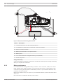
Figure 6.1: Non-power-limited wiring (B5512 shown)
Callout ᅳ Description
1 ᅳ Conduit required for use with external batteries
2 ᅳ To CX4010 UL Listed Class 2 Transformer 18 VAC 22 VA 60 Hz
3 ᅳ 0.25 in (6.4 mm) minimum
4 ᅳ Battery terminals. BAT- is non-power limited
5 ᅳ Battery wires
6 ᅳ 12 V sealed lead-acid rechargeable battery (D126/D1218)
7 ᅳ Sensor loop wires
Charge the battery
Connect the battery and then the transformer to allow the control panel to charge the battery
while you complete the installation.
6.2.2
Battery maintenance
Use sealed lead-acid rechargeable battery (12.0 VDC, 7 Ah or 12.0 VDC, 18 Ah). The control
panel supports up to 18 Ah of battery. If you use two D126 (12.0 VDC, 7 Ah) batteries, then
connect them using the D122/D122L Dual Battery Harness. If you install two batteries, they
must have the same capacity.
Replace the batteries every 3 to 5 years. If you install two batteries, replace them both at the
same time.
Record the date of installation directly on the battery.
2014.05 | 11 | F.01U.287.180
Installation and System Reference Guide
Bosch Security Systems, Inc.
Control Panel
Power supply | en
33
Caution!
!
Exceeding the maximum output ratings or installing the transformer in an outlet that is
routinely switched off causes heavy discharges. Routine heavy discharges can lead to
premature battery failure.
6.2.3
Battery supervision
The battery charging float level occurs at 13.65 VDC. If the battery voltage drops below 12.1
VDC, the control panel sends a LOW BATTERY report, if programmed to do so.
When the battery voltage drops to 10.2 VDC, the keypad or keypads show low battery
messages. The control panel (if programmed for power supervision) sends a Battery Low
report in the Modem4 communication format. It sends a Low System Battery (302) report in
the Contact ID format.
If programmed for power supervision, the control panel adds a missing battery event to the
event log. If programmed for battery fault reports, the control panel sends a BATTERY
MISSING report in the Modem4 communication format, or Control Panel Battery Missing (311)
report in the Contact ID format.
When battery voltage returns to 13.4 V, the keypads stop showing the low battery messages. If
the control panel is programmed for power supervision, it sends a BATTERY RESTORAL report
in the Modem4 communication format or a Control Panel Battery Restored to Normal (302)
report in the Contact ID format.
Investigate LOW BATTERY events immediately: If primary (AC) power is off and the discharge
continues, the control panel becomes inoperative when the battery voltage drops below 10.2
VDC.
6.2.4
Battery discharge and recharge schedule
Discharge cycle
13.65 VDC - Charging float level.
12.1 VDC - Low Battery Report, if programmed.
10.2 VDC - Minimum operational voltage.
Recharge cycle
AC ON - Battery charging begins and AC Restoral Reports sent.
13.4 V - Battery Restoral Report sent. Battery float charged.
Further information
Refer to Powered outputs, page 60.
6.3
B520 Auxiliary Power Supply
The optional B520 Auxiliary Power Supply Module provides up to 2 A of 12 VDC standby
power for Fire and Burglar applications. For Burglar applications, an additional 2 A of alarm
power is available, allowing 2 A of standby current and up to 4 A of alarm current. You can
connect more than one module to the control panel.
The B5512 control panels support up to 4 modules. The B4512/B3512 control panels support
up to 2 modules.
Connect B520 Auxiliary Power Supply Modules to the SDI2 bus on the control panel using
terminals PWR, A, B, and COM. This section includes basic installation instructions. For
detailed installation instructions, refer to the Auxiliary Power Supply Module (B520) Installation
Guide for complete installation instructions, and for battery standby time calculations, refer to
the B520 Auxiliary Power Supply Module Battery Standby Chart within the installation guide.
Bosch Security Systems, Inc.
Installation and System Reference Guide
2014.05 | 11 | F.01U.287.180
34
en | Power supply
6.3.1
Control Panel
SDI2 address settings
Notice!
The module reads the address switch setting only during power up. If you change the setting
after you apply power to the module, you must cycle the power to the module in order for the
new setting to be enabled.
If multiple B520 modules reside on the same system, each B520 module must have a unique
address.
Supervision
6.3.2
The control panel supervises B520 Auxiliary Power Supply Modules on the SDI2 bus.
With any failure to receive an expected response from an SDI2 module, all keypads show in a
system fault display. The control panel sends a module trouble report to the central station (if
configured for module trouble reports).
6.3.3
Auxiliary power supply trouble conditions
Each auxiliary power supply module on the SDI2 bus monitors several conditions including AC
status, battery status, over current status, and a tamper input. Each of these conditions
produces a unique system trouble condition at all keypads. The control panel sends a module
trouble report to the central station (if configured for module trouble reports).
When the control panel shows a generic trouble condition for a SDI2 bus power supply
module, it could mean one of several non-serviceable things has occurred; low power output,
module firmware flash error, or battery charger circuit failure.
6.3.4
Installation and control panel wiring (B520)
The power supply draws approximately 15 mA (+/- 1 mA) from the control panel.
Ensure that there is enough power for the module and other powered devices you want
connected to the system.
Refer to On-board outputs, page 60.
Caution!
!
Remove all power (AC and battery) before making any connections. Failure to do so might
result in personal injury and/or equipment damage.
Install the module
1. Install the enclosure on the wall using the instructions supplied with the enclosure.
2.
Set the module address using the address switches before you install it in the enclosure.
3.
Insert the plastic mounting clips onto the appropriate standoff locations inside the
enclosure or on a mounting skirt, when required.
4.
Mount the module onto the plastic mounting clips and then secure it using the supplied
mounting screws.
Wire to earth ground
To help prevent damage from electrostatic charges or other transient electrical surges,
connect the system to earth ground before making other connections. Recommended earth
ground references are a grounding rod or a cold water pipe. When grounding, run wire as
close as possible to grounding device.
2014.05 | 11 | F.01U.287.180
Installation and System Reference Guide
Bosch Security Systems, Inc.
Control Panel
Power supply | en
35
Caution!
!
Do not use telephone or electrical ground for the earth ground connection. Use 14 AWG (1.8
mm) to 16 AWG (1.5 mm) wire when making the connection.
Figure 6.2: B520 earth ground wiring
Callout ᅳ Description
1 ᅳ Power supply module
2 ᅳ 14 AWG - 16 AWG (1.8 mm - 1.5 mm) wire
3 ᅳ Ground device (grounding rod or cold water pipe)
Bosch Security Systems, Inc.
Installation and System Reference Guide
2014.05 | 11 | F.01U.287.180
36
en | Power supply
Control Panel
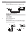
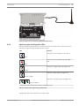
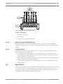
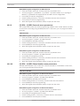
Wire to the control panel
When wiring a module to a control panel, use the terminal strip labeled with PWR, A, B, and
COM for SDI2 IN to wire to terminals labeled PWR, A, B, and COM on the control panel.
Use 12 AWG to 22 AWG (2 mm to 0.65 mm) wire.
SDI2 OUT
SDI2 IN
1k
AUX
- 12 V +
COM AUX
PWR A B COM
PWR A B COM
R Y
PWR A
G B
B COM
C
OUTPUT
B
End of Line Resistors
1 COM 2 3 COM 4
5 COM 6
7 COM 8
1
5
7
COM
2
3
COM
4
COM
6
COM
C
B
OUTPUT
2
ON-BOARD POINTS
Voltage Ranges
Open
3.7 - 5.0 VDC
Normal 2.0 - 3.0 VDC
Short
0.0 - 1.3 VDC
TMPR
SDI2
Device Bus
R Y G B
RESET
1
8
3
R
Y
G
B
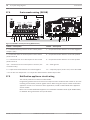
Figure 6.3: B520 to the control panel wiring (B5512 shown)
Callout ᅳ Description
1 ᅳ Control panel
2 ᅳ Power supply module
3 ᅳ Terminal strip wiring
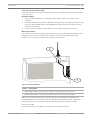
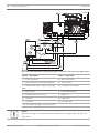
6.3.5
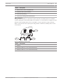
Powered device and battery wiring
Wire to SDI2 powered devices
When wiring the output of a B520 to a SDI2 module, you can use either the SDI2 OUT terminal
strip labeled with PWR, A, B, and COM to wire to terminals labeled PWR, A, B, and COM on
the next module, or you can use the interconnect wiring connector (included). Wiring the
output of a B520 to a SDI2 device provides power to the device while passing through data
between the control panel and the device.
1
SDI2 OUT
SDI2 IN
PWR A B COM
PWR A B COM
1
SDI2 OUT
SDI2 IN
PWR A B COM
PWR A B COM
R YGB
3
4
2
2
PWR A B COM
PWR A B COM
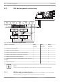
Figure 6.4: B520 to powered devices - terminal strip or interconnect wiring connector
2014.05 | 11 | F.01U.287.180
Installation and System Reference Guide
Bosch Security Systems, Inc.
Control Panel
Power supply | en
37
Callout ᅳ Description
1 ᅳ B520 Auxiliary Power Supply Module
2 ᅳ Powered device (SDI2 module)
3 ᅳ Terminal strip wiring
4 ᅳ Interconnect wiring (P/N: F01U079745)
Wire to batteries
Wiring the B520 to BATT 1 is required for proper operation of standby power for the B520
module. Wiring the second battery (BATT 2) is optional. If a control panel is configured for two
batteries as the standby power source, then BATT 2 is also required for proper operation.
BATT 2 must have the same capacity and rating as BATT 1. Maximum standby power cannot
exceed 36 Ah.
1
BATT
R
1
+
B
-
BATT
R
2
+
-
B
3
2
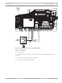
Figure 6.5: B520 BATT terminals wiring
Callout ᅳ Description
1 ᅳ Module
2 ᅳ Battery 2 (BATT 2) - (12 V nominal lead acid)
3 ᅳ Battery 1 (BATT 1) - (12 V nominal lead acid))
Bosch Security Systems, Inc.
Installation and System Reference Guide
2014.05 | 11 | F.01U.287.180
38
en | Telephone communications
Control Panel
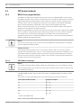
7
Telephone communications
7.1
B430 Plug-in Telephone Communicator
The B430 Plug-in Telephone Communicator provides communication over PSTN. The module
provides a single telephone interface RJ-45 connector for connecting the phone line. The
module plugs directly into the control panel with no additional connections required.
The control panel supports one plug-in module plugged directly into the control panel board.
This section includes basic installation instructions. For detailed installation instructions, refer
to the Plug-in Telephone Communicator (B430) Installation Guide.
Notification
The B430 module by Bosch Security Systems, Inc. is registered with the Federal
Communication Commission (FCC) under Part 68, for connection to the public telephone
system using an RJ31X or RJ38X phone line connection jack installed by the local telephone
company.
Do not connect registered equipment to party lines or coin-operated telephones. Notify the
local telephone company and provide the following information before connecting the control
panel to the telephone network:
–
The particular line to which you connect the module
–
Make (Bosch Security Systems, Inc.), model (B5512/B4512/B3512), and serial number of
the control panel
–
FCC registration number: ESVAL00BB430
–
Ringer eq: 0.0B
Supervision
7.1.1
The control panel supervises the phone line. You can configure the supervision time using
RPS.
Installation and module wiring (B430)
7.1.2
Ensure that there is enough power for the module and other powered devices you want
connected to the system.
Refer to On-board outputs, page 60.
Caution!
!
Remove all power (AC and battery) before making any connections. Failure to do so might
result in personal injury and/or equipment damage.
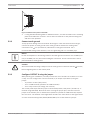
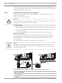
Install the module
The module plugs into a connector and is held in place with a plug-in module retention clip.
The module handle and support on top of the module hold the unit during installation.
Plug the module in to a control panel by aligning the module with the control panel’s on-board
connector. The retention clip has a locking device to help hold the card in position. Pull the
locking device back. Slide the module down until it seats firmly into the connector slot. The
locking handle will then click into pace holding the module in the socket.
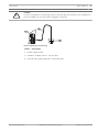
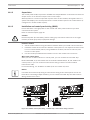
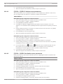
Wire to the phone line
The module has pads on both sides of the board to connect a test telephone set. Connect one
end of a D162 or D161 Modular Telephone Cord to the phone line, and connect the other end
to a RJ31X or RJ38X phone jack to make proper connection to the phone line.
2014.05 | 11 | F.01U.287.180
Installation and System Reference Guide
Bosch Security Systems, Inc.
Control Panel
Telephone communications | en
39
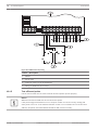
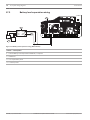
Figure 7.1: PTSN module wiring (B5512 shown)
Callout ᅳ Description
1 ᅳ Premises telephone
2 ᅳ Incoming Telco line
3 ᅳ Installer telephone test set
4 ᅳ RJ-45 phone connector
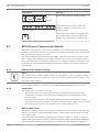
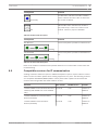
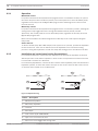
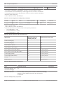
7.1.3
Diagnostic LEDs
The module uses a green LED to indicate when the module is on or off hook or the line is
ringing (incoming phone call).
Flash pattern
Function
OFF
Standby
ON
Line seized
Flash
Ringing detect (incoming phone call)
Table 7.1: PTSN diagnostic LED patterns
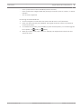
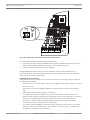
7.2
Phone jack location
To prevent jamming of signals, wire the RJ31X or RJ38X jack before the in-house telephone
system to support line seizure. Install the jack on the street side of the telephone switch,
wired ahead of any PBX equipment. Line seizure temporarily interrupts normal telephone
usage while the control panel sends data. After installation, confirm that the control panel
seizes the line, acquires dial tone, reports correctly to the receiver, and releases the telephone
line to the in-house telephone system.
Bosch Security Systems, Inc.
Installation and System Reference Guide
2014.05 | 11 | F.01U.287.180
40
en | Telephone communications
Control Panel
1
2
4
3
5
6
Figure 7.2: RJ31X/RJ38X wiring (RJ31X shown)
Callout ᅳ Description
1 ᅳ Outside Telco
2 ᅳ Premises telephone
3 ᅳ Bar short removed on Telco connector block insertion – positions 1 and 4 and 5 and 8
4 ᅳ RJ31X/RJ38X jack
5 ᅳ Telco connector block
6 ᅳ To control panel
7.3
Telephone line monitor
The B430 module has a built-in telephone line monitor that tests the telephone line for voltage
and current. The normal voltage on a telephone line is approximately 48 VDC (24 VDC for
some telephone systems).
If the module senses trouble, it starts a programmable telephone line trouble timer, which
continues to run as long as the monitor detects trouble. It resets to zero when the control
panel senses a normal line. If the timer reaches the delay time in the Phone Supervision
program item, it begins a telephone line trouble response. Programming determines what the
response is. For programming information, refer to Phone Parameters in RPS Help or in the
control panel's Program Entry Guide.
Notice!
Bad Line Might Test OK
The telephone line monitor uses voltage levels to test the status of the telephone line. In
some instances, a given telephone line might be out of service without affecting the voltage
on the line. The telephone line monitor cannot recognize this trouble condition.
2014.05 | 11 | F.01U.287.180
Installation and System Reference Guide
Bosch Security Systems, Inc.
Control Panel
7.4
Telephone communications | en
41
Called party disconnect
Telephone companies provide “called party disconnect” to allow the called party to terminate
a call. The called party must go on hook (hang up) for a fixed interval before a dial tone is
available for a new call. This interval varies with telephone company equipment. Control panel
firmware allows for “called party disconnect” by adding a 35-sec “on hook” interval to the dial
tone detect function. If the control panel does not detect a dial tone in 7 sec, it puts the
telephone line on hook for 35 sec to activate “called party disconnect,” goes off hook, and
begins a seven-sec dial tone detect. If no dial tone is detected, the control panel dials the
number anyway. Each time the control panel dials the number, the control panel records this
as an attempt.
7.5
Communication failure
If the control panel has a backup route configured and the first two attempts to reach the
receiver over the phone line fail, the system switches to the backup route. When it switches to
the backup route, it sends a trouble event, and the event that triggered the telephone call to
the central station follows.
After ten unsuccessful attempts to reach the receiver, the control panel enters communication
failure. The control panel clears any reports queued for the failed route and generates a
COMM FAIL event that shows on the keypads. A trouble sounder can be programmed to
annunciate at the keypads.
One hour after a COMM FAIL event, the control panel attempts to send a COMM RSTL event.
If a communication failure still occurs, the keypad trouble sounds again.
Bosch Security Systems, Inc.
Installation and System Reference Guide
2014.05 | 11 | F.01U.287.180
42
en | IP communications
8
Control Panel
IP communications
The control panel uses the optional on-board Ethernet connector, B440 Conettix Plug-in
Cellular Communicator, B441 Conettix Plug-in CDMA Cellular Communicator, B442 Plug-in
GPRS Cellular Communicator (Latin America), B443 Plug-in HSPA+ Cellular Communicator
(Canada), or B426 Conettix Ethernet Communication Module to communicate with a Conettix
D6600 or a Conettix D6100IPv6 Communications Receiver/Gateway. Using Conettix IP
communication offers a secure path that includes anti-replay/anti-substitution features and
provides enhanced security with AES 256-bit encryption. You can use the Ethernet connection
for remote programming.
The control panel supports Domain Name System (DNS) for both remote programming and
central station communication. DNS provides ease of use, eliminating the need to use static IP
addresses as your reporting destination, and accommodates a simple solution for central
station disaster recovery. IP Setup is available via the keypad Installer menu and the remote
programming software, eliminating the need to use complicated internet programming tools
such as ARP and Telnet. The control panel supports both IPv6 and IPv4 networks.
For more information on the enhanced communications capabilities, refer to RPS Help or the
control panel's Program Entry Guide.
Notice!
For premises equipment used in the communication path, such as routers, use only UL listed
equipment.
8.1
On-board Ethernet connection
The built-in Ethernet port on the control panels allows for a network connection without the
need for additional modules. The port supports both 10 Base-T (10 Mb) and 100 Base-TX (100
Mb) standards. The port supports full duplex, half duplex, and HP AUTO_MDIX communication,
using a standard Ethernet cable.
8.1.1
Supervision
The control panel supervises its on-board Ethernet connection when the control panel uses
the on-board Ethernet in any of the four route groups as part of either the primary route or the
backup route, or when the control panel uses the connection as the automation mode 1
device. Supervision ensures reliable operation of the Ethernet port.
If supervised and the on-board Ethernet does not respond to control panel supervision polls,
then a system fault message appears at the keypads. The control panel sends a corresponding
report to the central station.
8.1.2
Local RPS programming
Use the on-board Ethernet connection to locally connect with RPS. This connection method
requires a direct IP connection from the RPS computer to the on-board Ethernet port. You
must remove the Ethernet cable that connects the control panel to the network used for IP
communication for the duration of the RPS session (when applicable). Be sure to reconnect
the cable used for IP communication when you finish your RPS session.
8.1.3
On-board Ethernet diagnostic LEDs
The control panel includes the following on-board LEDs to assist with troubleshooting the onboard Ethernet connection.
2014.05 | 11 | F.01U.287.180
Installation and System Reference Guide
Bosch Security Systems, Inc.
Control Panel
IP communications | en
43
MODULE 1
MODULE
RELEASE
E 1
1
ETHERNET
2
ETHERNET
100BASE-T
LINK
USB
Figure 8.1: On-board Ethernet connector and LEDs (B5512 shown)
Callout ᅳ Description
Callout ᅳ Description
1 ᅳ 100BASE-T LED (green)
2 ᅳ LINK LED (yellow)
Refer to the following tables for information on the 100BASE-T and LINK LEDs.
Flash pattern
Function
Communicating at 100 Mb
On Steady
Communicating at 10 Mb.
Off
Table 8.1: 100BASE-T LED descriptions
Flash pattern
Function
Plugged into an Ethernet network.
On Steady
Communication in progress.
Flashing
Unplugged from an Ethernet network, or the Ethernet
network is not available.
Off
Table 8.2: LINK LED descriptions
8.2
Conettix Plug-in Cellular Communicators
Cellular plug-in communicators provide communication between the control panel and central
monitoring stations or RPS using a cellular network. The module also sends and receives SMS
messages for personal notification or system configuration.
The control panel supports one plug-in module.
Bosch Security Systems, Inc.
Installation and System Reference Guide
2014.05 | 11 | F.01U.287.180
44
en | IP communications
Control Panel
Connect a module using the plug-in module connector or using a B450 Conettix Plug-in
Communicator Interface (refer to the Conettix Plug-in Communicator Interface (B450)
Installation and Operation Guide and B450 Conettix Plug-in Communicator Interface, page 50).
This section includes basic installation instructions. For detailed instructions, refer to the
corresponding Conettix plug-in module document listed in Optional module documents, page
12.
Supervision
8.2.1
The control panel supervises a plug-in cellular communicator when the control panel uses the
module in any of the four route groups as part of either the primary route or the backup route,
and the control panel uses the module to route any personal notifications. Supervision
ensures reliable operation between the module and the control panel.
If supervised and the module does not respond to control panel supervision polls, then a
system fault message shows on the keypads. The control panel sends a corresponding report
to the central station.
Installation and module wiring (B44x)
8.2.2
Ensure that there is enough power for the module and other powered devices you want
connected to the system.
Refer to On-board outputs, page 60.
Caution!
!
Remove all power (AC and battery) before making any connections. Failure to do so might
result in personal injury and/or equipment damage.
Install the module
The module plugs into a connector and is held in place with a plug-in module retention clip.
The module handle and support on top of the module hold the unit during installation.
Plug the module in to a control panel by aligning the module with the control panel’s on-board
connector. The retention clip has a locking device to help hold the card in position. Pull the
locking device back. Slide the module down until it seats firmly into the connector slot. The
locking handle will then click into pace holding the module in the socket.
Wire to the antenna
The module has a threaded connector for connection to an antenna. Route the antenna cable
through a wire knockout in the top of the enclosure. Connect the antenna cable to the
module. Secure the antenna cable to the outside of the enclosure.
2014.05 | 11 | F.01U.287.180
Installation and System Reference Guide
Bosch Security Systems, Inc.
Control Panel
IP communications | en
45
Figure 8.2: Plug-in celluar module wiring (B440 and B5512 shown)
8.2.3
Signal strength and diagnostic LEDs
Five LED patterns indicate that you correctly secured the module in the control panel, and
indicate the signal strength obtained by the module.
LED
Function
Indicates the overall status of the device.
Blue
Indicates an unacceptable signal strength
level.
Red
Indicates a marginal signal strength level.
Yellow
Indicates a good signal strength level.
Green (1 light)*
Indicates a very good signal strength level.
Green (2 lights)
* One green LED indicates the minimum installation level.
Table 8.3: Cellular module signal strength LED patterns
A single blue Status LED indicates the module status.
Bosch Security Systems, Inc.
Installation and System Reference Guide
2014.05 | 11 | F.01U.287.180
46
en | IP communications
Control Panel
Flash pattern
Function
Normal state. Indicates normal operation.
Flashes
once every 1 sec
Communication error state. Indicates the
module is unable to communicate on the
3 quick flashes
cellular network.
LED trouble state. Module is not powered, or
some other trouble condition prohibits the
module from controlling the heartbeat LED.
Off
Table 8.4: Cellular module diagnostic LED patterns
8.3
B426 Ethernet Communication Module
The B426 Conettix Ethernet Communication Module is a four-wire powered SDI2 device that
provides connection for two-way communication over Ethernet networks to the control panels.
The control panel supports one module.
The B426 Conettix Ethernet Communication Module connects to the SDI2 bus on the control
panel using terminals PWR, A, B, and COM, or using the SDI2 interconnect wiring connector.
This section includes basic installation instructions. For detailed installation instructions, refer
to the Conettix Ethernet Communication Module (B426) Installation and Operation Guide (P/N:
F01U281208).
8.3.1
Address and emulation settings
Notice!
The module reads the address switch setting only during power up. If you change the setting
after you apply power to the module, you must cycle the power to the module in order for the
new setting to be enabled.
Set the address switch to 1 to use the module with a B5512/B4512/B3512 control panel.
8.3.2
Supervision
The control panel supervises in two ways:
–
Module supervision. The control panel supervises the module through polling. If the
module does not respond to the control panel polling, the control panel declares the
device missing.
–
Communication supervision. The control panel supervises the communication path by
polling the central station receiver. If the poll is missed from either side, a communication
fault is declared both at the control panel and the central station receiver.
8.3.3
B426 module faults
With a B426 installed, several services become available to the control panel. Any break in the
Ethernet connection to a supervised B426 results in a system fault at the keypads indicating
Open Cable trouble.
If a Domain Name Server (DNS) is available on the network, a failure to resolve an individual
Network Address hostname results in a system fault at the keypads indicating DNS ERROR ##.
The error number represents the communication module and path destination combination
2014.05 | 11 | F.01U.287.180
Installation and System Reference Guide
Bosch Security Systems, Inc.
Control Panel
IP communications | en
47
that failed. Refer to RPS Help or the control panel's Program Entry Guide for details on
communication module/path destination combinations. The keypad shows a failure to resolve
the domain name used for RPS Network Address.
If a B426 fails all communication with the DNS, a system fault indicating Network Module #
Address Error shows on all keypads and the control panel sends a trouble event to the central
stations, if enabled.
8.3.4
Local RPS programming
Use the B426 IP Direct connect feature to locally connect with RPS. This connection method
requires a direct IP connection from the RPS computer to the B426 Ethernet port. You must
remove the Ethernet cable that connects the B426 to the web for the duration of the IP direct
connection. Be sure to reconnect the B426 to the internet when you finish.
The IP Direct connection for RPS uses the B426 AutoIP configuration. Refer to the Conettix
Ethernet Communication Module (B426) Installation and Operation Guide for configuration
information. This connection method also allows diagnostic and history retrieval.
8.3.5
Installation and control panel wiring (B426)
Ensure that there is enough power for the module and other powered devices you want
connected to the system.
Refer to On-board outputs, page 60.
Caution!
!
Remove all power (AC and battery) before making any connections. Failure to do so might
result in personal injury and/or equipment damage.
Install the module
1. Set the module address to one using the address switch before you install it in the
enclosure.
2.
Install the module in the enclosure with the control panel or in an adjacent enclosure that
is no more than 1000 ft (305 m) using 18 AWG to 22 AWG (1.02 mm to 0.65 mm) wire
from the control panel.
3.
Use the screws provided with the module to secure the module in the enclosure.
Wire to the control panel
When you wire an SDI2 module to a control panel, you can use either the terminal strip
labeled with PWR, A, B, and COM to wire to terminals labeled PWR, A, B, and COM on the
control panel, or you can use the P6 interconnect wiring connector and the included
interconnect cable.
For terminal wiring, use 18 AWG to 22 AWG (1.02 mm to 0.65 mm) wire.
Notice!
Use either the terminal strip wiring or interconnect wiring to the control panel. Do not use
both. When connecting multiple modules, you can combine terminal strip and interconnect
wiring connectors in series.
Bosch Security Systems, Inc.
Installation and System Reference Guide
2014.05 | 11 | F.01U.287.180
1k
AUX
- 12 V +
COM AUX
R Y
PWR A
G B
B COM
C
OUTPUT
B
End of Line Resistors
1 COM 2 3 COM 4
5 COM 6
7 COM 8
1
5
7
COM
2
3
COM
4
COM
6
COM
ON-BOARD POINTS
Voltage Ranges
Open
3.7 - 5.0 VDC
Normal 2.0 - 3.0 VDC
Short
0.0 - 1.3 VDC
1k
AUX
- 12 V +
8
COM AUX
R Y
PWR A
2
G B
B COM
RESET
SDI2
Device Bus
R Y G B
1
C
OUTPUT
B
End of Line Resistors
1 COM 2 3 COM 4
5 COM 6
7 COM 8
1
5
7
COM
2
3
COM
4
COM
6
COM
C
B
OUTPUT
ON-BOARD POINTS
Voltage Ranges
Open
3.7 - 5.0 VDC
Normal 2.0 - 3.0 VDC
Short
0.0 - 1.3 VDC
TMPR
SDI2
Device Bus
R Y G B
C
B
OUTPUT
1
Control Panel
RESET
en | IP communications
TMPR
48
8
4
3
R
Y
G
B
R
R
2
Y
Y
G
G
B
B
Figure 8.3: B426 to control panel wiring - terminal strip or interconnect wiring connector (B5512 shown)
Callout ᅳ Description
1 ᅳ Control panel
2 ᅳ Module
3 ᅳ Terminal strip wiring
4 ᅳ Interconnect cable (P/N: F01U079745) (included)
Wire to the network
The module has an Ethernet RJ-45 port for connection to an Ethernet network. Connect an
Ethernet cable between the Ethernet jack on the module and a network jack.
1
2
R
Y
G
B
Figure 8.4: B426 to Ethernet wiring
Callout ᅳ Description
1 ᅳ B426 module
2 ᅳ Ethernet cable
8.3.6
Diagnostic LEDs
The B426 includes the following on-board LEDs to assist with troubleshooting:
–
Heartbeat (system status).
–
RX (receive).
–
TX (transmit).
Refer to B426 module overview for Ethernet link LED locations.
2014.05 | 11 | F.01U.287.180
Installation and System Reference Guide
Bosch Security Systems, Inc.
Control Panel
IP communications | en
Flash pattern
49
Function
Normal state. Indicates normal operation state.
Flashes once every 1 sec
Communication error state. Indicates a bus communication
error. The module is not receiving commands from the
3 quick flashes every 1 sec
control panel.
Trouble state. Indicates a trouble condition exists.
On Steady
LED trouble state. Module is not powered, or some other
trouble condition prohibits the module from controlling the
heartbeat LED.
Off
Table 8.5: Heartbeat LED descriptions
Flash pattern
Function
Occurs when the module receives a message over the
network connection – UPD, TCP, or DNS.
RX (Receive) Flashing
Occurs when the module sends a message over the
network connection – UPD, TCP, or DNS.
TX (Transmit) Flashing
Table 8.6: RX and TX LEDs descriptions
LINK (yellow) LED pattern
100Mb (green) LED pattern
Function
No Ethernet link
Off
Off
10Base-T link
On Steady
Off
10Base-T activity
Flashing
Bosch Security Systems, Inc.
Off
Installation and System Reference Guide
2014.05 | 11 | F.01U.287.180
50
en | IP communications
Control Panel
LINK (yellow) LED pattern
100Mb (green) LED pattern
Function
100Base-TX link
On Steady
On Steady
100Base-TX activity
On Steady
Flashing
Table 8.7: Ethernet Link LEDs descriptions
B450 Conettix Plug-in Communicator Interface
8.4
The B450 Conettix Plug-in Communicator Interface gives the ability to connect more than one
cellular plug-in communicator to the control panel by providing an interface to the control
panel’s SDI2 wiring.
The B450 supports one cellular plug-in module.
B450 Conettix Plug-in Communicator Interface connects to the SDI2 bus on the control panel
using terminals PWR, A, B, and COM, or using the SDI2 interconnect wiring connector. This
section includes basic installation instructions. For detailed installation instructions, refer to
the Conettix Plug-in Communicator Interface (B450) Installation and Operation Guide.
SDI2 address settings
8.4.1
Notice!
The module reads the address switch setting only during power up. If you change the setting
after you apply power to the module, you must cycle the power to the module in order for the
new setting to be enabled.
The control panel supports one module. Set the address switch to 1 to use the module with a
B5512/B4512/B3512 control panel.
Supervision
8.4.2
The control panel supervises in two ways:
–
Module supervision. The control panel supervises the module through polling. If the
module does not respond to the control panel polling, the control panel declares the
device missing.
–
Communication supervision. The control panel supervises the communication path by
polling the central station receiver. If the poll is missed from either side, a communication
fault is declared both at the control panel and the central station receiver.
Installation and control panel wiring (B450)
8.4.3
Ensure that there is enough power for the module and other powered devices you want
connected to the system.
Refer to On-board outputs, page 60.
Caution!
!
Remove all power (AC and battery) before making any connections. Failure to do so might
result in personal injury and/or equipment damage.
2014.05 | 11 | F.01U.287.180
Installation and System Reference Guide
Bosch Security Systems, Inc.
Control Panel
IP communications | en
51
Insert the communication module
Insert the desired communication module into the slot of the B450 until you hear the module
“click” into place.
Install the module
1. Set the module address to one using the address switch before you install it in the
enclosure.
2.
Install the module in the enclosure with the control panel or in an adjacent enclosure that
is no more than 1000 ft (305 m) using 18 AWG to 22 AWG (1.02 mm to 0.65 mm) wire
from the control panel.
3.
Use the screws provided with the module to secure the module in the enclosure.
Wire to the antenna
The module has a threaded connector for connection to an antenna. Route the antenna cable
through a wire knockout in the top of the enclosure. Connect the antenna cable to the
module. Secure the antenna cable to the outside of the enclosure.
1
2
Figure 8.5: Antenna installation
Callout ᅳ Description
1 ᅳ B44x plug-in cellular communicator antenna (routed through any knock-out)
2 ᅳB44x plug-in cellular communicator antenna cable (connected to the module)
When you wire an SDI2 module to a control panel, you can use either the terminal strip
labeled with PWR, A, B, and COM to wire to terminals labeled PWR, A, B, and COM on the
control panel, or you can use the P6 interconnect wiring connector and the included
interconnect cable.
For terminal wiring, use 18 AWG to 22 AWG (1.02 mm to 0.65 mm) wire.
Bosch Security Systems, Inc.
Installation and System Reference Guide
2014.05 | 11 | F.01U.287.180
52
en | IP communications
Control Panel
Notice!
Use either the terminal strip wiring or interconnect wiring to the control panel. Do not use
both. When connecting multiple modules, you can combine terminal strip and interconnect
1k
AUX
- 12 V +
COM AUX
R Y
PWR A
G B
B COM
End of Line Resistors
1 COM 2 3 COM 4
5 COM 6
7 COM 8
1
5
7
COM
2
3
COM
4
COM
6
COM
1
ON-BOARD POINTS
Voltage Ranges
Open
3.7 - 5.0 VDC
Normal 2.0 - 3.0 VDC
Short
0.0 - 1.3 VDC
1k
AUX
- 12 V +
8
COM AUX
R Y
PWR A
2
G B
B COM
RESET
SDI2
Device Bus
R Y G B
C
OUTPUT
B
End of Line Resistors
1 COM 2 3 COM 4
5 COM 6
7 COM 8
1
5
7
COM
2
3
COM
4
COM
6
COM
C
B
OUTPUT
C
OUTPUT
B
TMPR
ON-BOARD POINTS
Voltage Ranges
Open
3.7 - 5.0 VDC
Normal 2.0 - 3.0 VDC
0.0 - 1.3 VDC
Short
C
B
OUTPUT
SDI2
Device Bus
R Y G B
TMPR
1
RESET
wiring connectors in series.
8
4
3
2
R
Y
G
B
R
R
Y
Y
G
G
B
B
Figure 8.6: B450 to control panel wiring - terminal strip or interconnect wiring connector (B5512 shown)
Callout ᅳ Description
1 ᅳ Control panel
2 ᅳ Module
3 ᅳTerminal strip wiring
4 ᅳ Interconnect cable
8.4.4
Diagnostic LEDs
The B450 includes the following on-board LEDs to assist with troubleshooting:
–
Heartbeat (system status).
–
RX (receive).
–
TX (transmit).
The plug-in module also includes LEDs for troubleshooting and status.
Flash pattern
Function
Normal state. Indicates normal operation.
Flashes
once every 1 sec
Communication error state. Indicates a bus
communication error with the control panel.
3 quick flashes every 1 sec
2014.05 | 11 | F.01U.287.180
Installation and System Reference Guide
Bosch Security Systems, Inc.
Control Panel
IP communications | en
Flash pattern
53
Function
Trouble state. Indicates a trouble condition
exists. Examine the other LEDs to determine
the trouble condition.
On Steady
LED trouble state. Indicates the module is
not powered up, or there is a failure in the
module. Check for proper installation.
Off
Table 8.8: Heartbeat LED descriptions
Flash pattern
Function
RX (Receive)
Occurs every time a packet is received on-air.
Flashing
Occurs every time a packet is transmitted on-
TX (Transmit)
air.
Flashing
Table 8.9: RX and TX LED descriptions
Refer to the module’s Installation and Operation Guide for more information on the LEDs and
troubleshooting.
8.5
Compatible receivers for IP communication
Sending Conettix IP Ethernet reports or Modem4 telephone reports requires a Bosch central
station receiver firmware update when existing equipment is in place. The following receivers
are compatible with B5512/B4512/B3512 control panels when updated to the listed CPU
versions and managed with the listed software version:
Receiver
CPU version
Conettix D6600 Communications Receiver/ 01.10.00
D6200 version
Formats
2.00
Contact ID
Gateway (with D6641 line cards installed
Modem4
only)
Conettix D6100IPv6 Communications
61.10.00
2.00
Receiver/Gateway
Modem4
Conettix D6100i Communications
61.10.00
Receiver/Gateway
Bosch Security Systems, Inc.
Contact ID
2.00
Contact ID
Modem4
Installation and System Reference Guide
2014.05 | 11 | F.01U.287.180
54
en | Keypads, keyswitches, keyfobs and transmitters
9
Control Panel
Keypads, keyswitches, keyfobs and transmitters
The system can use keypads, maintained or momentary contact keyswitches, wireless RADION
keyfobs or Inovonics transmitters, or a combination of these options to turn areas on and off.
B5512 control panels support up to 4 areas. B4512 control panels support up to 2 areas.
B3512 control panels support 1 area.
Refer to Areas and accounts, page 20 for a description of areas.
9.1
Keypads
Keypads are four-wire powered devices used to show system status and operate the system
(turn areas on or off for example). Keypads connect to the control panel through the SDI2 bus.
B5512/B4512 control panels support up to 8 keypads, in any combination of SDI2 keypad
models. B3512 support up to 4 keypads.
SDI2 keypads connect to the SDI2 bus on the control panel using terminals PWR, A, B, and
COM.
You can connect more than one keypad to the control panel by wiring them in parallel.
The control panel sends a trouble report if it loses communication with a keypad and a
message appears on all keypads.
All SDI2 keypads have:
–
User-adjustable volume
–
Keypress tones
–
A nightlight feature
–
A display that shows system messages
–
A sounder that emits warning tones
–
Highly visible status indicators
–
Backlit keys, with seven configurable backlight settings ranging from 0% to 100%
This section includes basic installation instructions for compatible keypads. For detailed
installation instructions, refer to the corresponding keypad document listed in Keypad
documents, page 12.
9.1.1
B915 Basic Keypad
The B915 Basic Keypad is an SDI2 bus compatible device. It offers the same commands and
menu structure as the other B Series keypads.
9.1.2
B920 Two-line Alphanumeric Keypad
The B920 Two-line Alphanumeric Keypad (SDI2) is an SDI2 bus compatible device. The display
shows two lines, 18 characters per line. Each keypad has 10 number keys and seven function
keys.
9.1.3
B921C Two-line Capacitive Keypad with Inputs
The B921C/B921CW Two-line Capacitive Keypad is an SDI2 bus compatible device. The
keypad features capacitive keys. The keypad detects open, short, normal, and ground fault
circuit conditions on its sensor loops and transmits the conditions to the control panel. Each
sensor loop is assigned a point number and transmits to the control panel individually.
9.1.4
B930 ATM Style Alphanumeric Keypad
The B930 ATM Style Alphanumeric Keypad (SDI2) is an SDI2 bus compatible device. The
keypad features a bright five line display and eight softkeys.
2014.05 | 11 | F.01U.287.180
Installation and System Reference Guide
Bosch Security Systems, Inc.
Control Panel
9.1.5
Keypads, keyswitches, keyfobs and transmitters | en
55
B942 Touch Screen Keypad
The B942/B942W is an SDI2 bus compatible device. Each keypad has a credential reader, a
presence sensor, a graphical interface for controlling the system, touch screen keys for data or
command entry.
The keypad detects open, short, normal, and ground fault circuit conditions on its sensor
loops and transmits the conditions to the control panel. Each sensor loop is assigned a point
number and transmits to the control panel individually. The keypad includes one output.
9.1.6
Shortcuts and custom functions
B Series keypads include a Shortcuts feature. Shortcuts allow you to assign commonly used or
custom functions to a Shortcuts menu. You create and assign shortcuts to keypads using RPS.
Custom functions
Custom functions allow you to combine multiple functions into a single function. Initiate
custom functions from keypads by assigning them to the Shortcut menu.
Use RPS to create custom functions, give them a name, and assign them to a Shortcut.
The user must have the appropriate authority level enabled to use the custom function.
For more information on creating custom functions, assigning authority levels to the functions,
assigning custom functions to a keypad’s Shortcuts, and other methods for initiating custom
functions, refer to RPS Help or the control panel's Program Entry Guide.
9.1.7
Address settings
The control panel uses the keypad’s address setting for communication and bus supervision.
If multiple keypads reside on the same system, each keypad must have a unique address.
9.1.8
Supervision
The control panel supervises all enabled keypads. Setting the keypad scope parameter to No
Keypad disables the keypad at that address. Disabled keypads are not supervised.
Any failure to receive an expected response from a keypad results in a system fault (missing
keypad) shows on all keypads. The control panel sends a keypad missing report to the central
station, if configured.
9.1.9
Installation and control panel wiring (keypads)
Ensure that there is enough power for the keypad and other powered devices you want
connected to the system.
Refer to On-board outputs, page 60.
Installing a keypad:
1.
Open the keypad.
2.
Set the keypad address using the address switches
3.
Use the provided anchors and screws to mount the keypad base on the wall.
4.
Pull the necessary wiring through the mounting plate. Refer to Wire to the control panel,
5.
Install the keypad on the base.
page 55.
Wire to the control panel
You connect B Series keypads to the SDI2 data bus by parallel wire run from the control panel
to each keypad, wire from keypad to keypad, or a combination of the two. Use a maximum of
7500 ft (2286 m) of 22 AWG (0.8 mm) wire for all devices connected to the SDI2 bus
combined.
Bosch Security Systems, Inc.
Installation and System Reference Guide
2014.05 | 11 | F.01U.287.180
56
en | Keypads, keyswitches, keyfobs and transmitters
Control Panel
ON-BOARD POINTS
Voltage Ranges
Open
3.7 - 5.0 VDC
Normal 2.0 - 3.0 VDC
Short
0.0 - 1.3 VDC
1k
AUX
- 12 V +
COM AUX
R Y
PWR A
G B
B COM
C
OUTPUT
B
End of Line Resistors
1 COM 2 3 COM 4
5 COM 6
7 COM 8
1
5
7
COM
2
3
COM
4
COM
6
COM
C
B
OUTPUT
SDI2
Device Bus
R Y G B
TMPR
1
RESET
Keypad to control panel wiring (B5512 shown)
8
2
3
R
Y
G
B
1 control panel
2 Keypad
3 Terminal strip wiring
Wire SDI2 keypads to the control panel
You connect B Series keypads to the SDI2 data bus by parallel wire run from the control panel
to each keypad, wire from keypad to keypad, or a combination of the two. Use a maximum of
7500 ft (2286 m) of 22 AWG (0.8 mm) wire for all devices connected to the SDI2 bus
combined.
SDI2 keypad to control panel wiring (B9512 shown)
Add figure!
Wire SDI keypads to the control panel
You connect SDI keypads to the SDIx data bus by parallel wire run from the control panel to
each keypad, wire from keypad to keypad, or a combination of the two. Use a maximum of
7500 ft (2286 m) of 22 AWG (0.8 mm) wire for all devices connected to the SDIx bus
combined.
SDI keypad to control panel wiring (B9512 shown)
Add figure!
9.1.10
Sensor loops overview and wiring (B921C/B942/B942W only)
Only the resistance on the loop limits the number of normally-open or normally-closed
detection devices each sensor loop can supervise. Resistance on each sensor loop must be
less than 100 Ω with the detection devices connected.
The keypad detects circuit conditions on its sensor loops and sends the conditions to the
control panel. Each sensor loop has an assigned point number.
Use twisted-pair wire for the module sensor loops to avoid electromagnetic interference
problems. Run wires away from the premises telephone and AC wiring.
To wire detection devices to keypad inputs, connect them to the keypad terminals labeled for
COM, and 1, 2, 3, or 4. Wire resistance on each sensor loop must be less than 100 Ω with the
detection devices connected. The terminal strip supports 12 to 22 AWG (0.65 to 2 mm) wires.
2014.05 | 11 | F.01U.287.180
Installation and System Reference Guide
Bosch Security Systems, Inc.
Control Panel
Keypads, keyswitches, keyfobs and transmitters | en
57
1COM2 3COM4
Figure 9.1: Keypad inputs wiring (B921C shown)
Callout ᅳ Description
1 ᅳ Keypad terminal strip
2 ᅳ Sensor loop
3 ᅳ 1 kΩ EOL resistor (P/N: F01U026703)
9.1.11
Output wiring (B942/B942W only)
The keypad provides one NO (normally open) output. (It includes NO and C (COMMON)
terminals.) When the output is in an active (energized) state, the NO has continuity with the C
terminal.
9.1.12
Troubleshooting
Keypads show a Call for Service message when they cannot communicate with the control
panel. The most common causes are:
1.
The address switch on the keypad is set to an address that is not programmed in the
control panel. Change the address switch to the proper address, or program the control
panel using RPS or a different keypad.
2.
If your keypads are not powered from the control panel, the control panel might have lost
power. Confirm the control panel has power.
3.
The wiring from the keypad to the control panel is not correct or has failed. Resolve any
wiring problems.
9.2
Keyswitches
You can connect a maintained or momentary contact keyswitch to turn an area All On (armed)
or Off (disarmed). Connect the keyswitch to an on-board or off-board point’s sensor loop. You
can program outputs to activate arming status LEDs. Refer to Outputs in RPS Help and Point
Assignments in the control panel's Program Entry Guide.
Bosch Security Systems, Inc.
Installation and System Reference Guide
2014.05 | 11 | F.01U.287.180
58
en | Keypads, keyswitches, keyfobs and transmitters
9.2.1
Control Panel
Operation
Maintained contact
For points connected to the keyswitch and programmed for a maintained contact, an open on
the sensor loop turns the area All On (armed). The control panel force arms all faulted points,
regardless of the entry in the FA Bypass Max program item. Returning the circuit to normal
turns the area off.
Momentary contact
For points connected to the keyswitch and programmed for a momentary contact, shorting the
arming sensor loop toggles the area's arming state between All On (armed) and Off
(disarmed). The control panel force arms all faulted points, regardless of the entry in the FA
Bypass Max program item.
Refer to Area Parameters and Point Assignments in RPS Help or the control panel's Program
Entry Guide.
Silence the bell
To silence the bell (stop Alarm Bell output) if the system is On (armed), operate the keyswitch
to turn the area off. If the area is disarmed, turn the keyswitch once to start the arming
process. Turning the keyswitch a second time stops the arming process and silences the bell.
9.2.2
Installation and control panel wiring (keyswitches)
For maintained switches, connect the EOL resistor for the point at the keyswitch so that the
switch opens the circuit when it operates. A short on the circuit produces an alarm if the area
is armed and a trouble if it is disarmed.
For momentary keyswitches, connect the EOL resistor at the keyswitch point so that when the
keyswitch operates, it shorts the resistor. An open on the circuit causes an alarm if the area is
on (armed) and a trouble if it is off (disarmed).
2
1
6
7
3
3
5
4
5
4
Figure 9.2: Keyswitch wiring
Callout ᅳ Description
1 ᅳ Maintained keyswitch
2 ᅳ Momentary keyswitch
3 ᅳ Common
4 ᅳ Point input
5 ᅳ 1 kΩ resistor (P/N: 4998143839)
6 ᅳ Open on a circuit arms the area
7 ᅳ Short on a circuit toggles the arming state
2014.05 | 11 | F.01U.287.180
Installation and System Reference Guide
Bosch Security Systems, Inc.
Control Panel
Keypads, keyswitches, keyfobs and transmitters | en
59
Keyswitches are not intended for use in UL listed systems.
9.3
RADION keyfobs and Inovonics pendant transmitters
B5512 control panels support up to 50 wireless RADION keyfobs or 50 Inovonics pendant
transmitters, one for each of the 50 users the control panel supports. B4512 control panels
support up to 32 wireless RADION keyfobs or 32 Inovonics pendant transmitters, one for each
of the 32 users the control panel supports. B3512 control panels support up to 10 wireless
RADION keyfobs or 10 Inovonics pendant transmitters, one for each of the 10 users the
control panel supports.
The control panels support two RADION keyfob models, RFKF-FB-A and RFKF-TB-A, that
communicate with the control panel using the RADION receiver SD. The control panels
support several Inovonics pendant transmitter models.
RADION keyfob FB
The RFKF-FB-A four button keyfob is designed for arming (lock icon) and disarming (unlock
icon) the system remotely. You can configure the programmable buttons at the control panel
for additional control functionality. To operate the programmable buttons, simply press and
hold either button for at least one sec in order for the desired feature to work.
–
Uniquely coded arm and disarm buttons
–
Panic alarm
–
LED indicator
–
Programmable option buttons
RADION keyfob TB
The RFKF-TB-A two button keyfob is designed for arming (lock icon) and disarming (unlock
icon) the system remotely. To operate these buttons, simply press and hold either button for
at least one sec in order for the desired feature to work.
–
Uniquely coded arm and disarm buttons
–
Panic alarm
–
LED indicator
Notice!
For specific installation and operation instructions, please refer to the RADION keyfob (RFKFFB-TB/RFKF-FB-TB-A) Installation Guide (P/N: F01U261820) and the RADION receiver SD (B810)
System Reference Guide.
Custom functions and the RADION keyfob FB
Using RPS, you can assign two custom functions to a RADION keyfob FB, allowing a user to
initiate the functions wirelessly. For more information, refer to RPS Help or the control panel's
Program Entry Guide.
Bosch Security Systems, Inc.
Installation and System Reference Guide
2014.05 | 11 | F.01U.287.180
60
en | On-board outputs
Control Panel
10
On-board outputs
10.1
Powered outputs
10.1.1
Circuit protection
Three self-resetting circuit breakers protect the control panel from short circuits on the
continuous and programmable power outputs.
If programmed for power supervision, the control panel adds a missing battery event to the
event log. If programmed for battery fault reports, the control panel sends a BATTERY
MISSING report in the Modem4 communication format, or Control Panel Battery Missing (311)
report in the Contact ID format.
One self-resetting circuit breaker protects the AUX (auxiliary power) terminal.
Another self-resetting circuit breaker protects the OUTPUT A’s C terminal.
The third self-resetting circuit breaker protects PWR/R terminal (power) of the SDI2 terminal
block.
Notice!
UL requires any device powered from a power output to be supervised.
10.1.2
Total available power
The control panel produces up to 800 mA of combined power at 12.0 VDC nominal to power
peripheral devices. The outputs listed below and OUTPUT A share the available power.
AUX terminal (auxiliary power)
AUX
Powers devices requiring continuous power (for example, motion detectors).
R/PWR terminal and power output of the interconnect connector (SDI2 power)
R
PWR
Power SDI2 devices such as a B208 Octo-input Module, a B308 Octo-output Module, or B920/
B930 keypads.
Plug-in module connector
Connect plug-in modules such as the B440 Conettix Plug-in Cellular Communicator.
OUTPUT A
NO C NC
OUTPUT A
Output A can be configured as a dry contact (contact rating is 3 Amps), switched common
(sink current), or a powered output. As a powered output, it can provide alarm power or
switched auxiliary power. The default configuration for Output A makes it a powered output
providing alarm power. Use OUTPUT PARAMETERS in RPS to configure programmable
outputs.
2014.05 | 11 | F.01U.287.180
Installation and System Reference Guide
Bosch Security Systems, Inc.
Control Panel
On-board outputs | en
61
Refer to Configure OUTPUT A using the jumper, page 27.
10.2
Open collector outputs
OUTPUT B and C
B
C
OUTPUT
Outputs B and C are open collector outputs that can sink up to 50 mA of power (+12 VDC),
when activated.
As an example, the figure below shows using Outputs B and C to trigger the relays of a D134
Dual Relay Module.
1
COMMUNICATION MODULE 1
ETHERNET
ETHERNET
100BASE-T
LINK
OUTPUT A
Jumper Under Cover
SDI2
Device Bus
R Y G B
ON-BOARD POINTS
Voltage Ranges
Open
3.7 - 5.0 VDC
Normal 2.0 - 3.0 VDC
Short
0.0 - 1. 3 VDC
1k
18 VAC
BATTERY
AUX
OUTPUT A - 12 V +
RESET
N/O 1
C
OUTPUT
B
End of Line Resistors
1 COM 2 3 COM 4
5 COM 6
7 COM 8
1
5
7
C
B
OUTPUT
OUTPUT A
USB
TMPR
AUX PWR
COM
DRY
2
COMM 1
N/C 1
X1 X1 +
N/O 2
COMM 2
N/C 2
18VAC
+ BAT -
NO C NC COM AUX R Y
PWR A
OUTPUT A
G B
B COM
COM
2
3
COM
4
COM
6
COM
8
X2 X2 +
Figure 10.1: OUTPUT B and C wiring (B5512 shown)
Callout ᅳ Description
1 ᅳ Control panel
2 ᅳ D134 Dual Relay Module
Use OUTPUT PARAMETERS in RPS to configure programmable outputs.
Bosch Security Systems, Inc.
Installation and System Reference Guide
2014.05 | 11 | F.01U.287.180
62
en | Off-board outputs
Control Panel
11
Off-board outputs
11.1
B308 Octo-output Module
The B308 is an eight output expansion device that connects to B5512/B4512 control panels
through the SDI2 bus. This module is supervised for the connection to the SDI bus. It provides
eight independently controlled outputs. Each output can operate as either normally open or
normally closed. You can configure the function for each output on the module individually.
Refer to Output Parameters in RPS Help or the control panel's Program Entry Guide.
B5512 control panels support up to 5 modules to provide 40 outputs. B4512 control panels
support up to 3 modules to provide 24 outputs.
B308 Octo-output Modules connect to the SDI2 bus on the control panel using terminals PWR,
A, B, and COM, or using the SDI2 interconnect wiring connector. You can connect more than
one module to the control panel by wiring them in parallel. This section includes basic
installation instructions. For detailed installation instructions, refer to the Octo-output Module
(B308) Installation and Operation Guide.
Notice!
Do not connect fire and non-fire devices to the same B308 Octo-output Modules. The B3512
does not support the B308 module.
Outputs overview
Each module output provides a Form C dry contact rated for .001 to 1.0 A at 5 to 24 VDC
(resistive load). Normally-open, common, and normally-closed terminals are available for each
relay output. When an individual output is activated, continuity exists between the normally
open and common terminals. When the output is not activated, continuity exists between the
normally closed and common terminals.
11.1.1
SDI2 address settings
Notice!
The module reads the address switch setting only during power up. If you change the setting
after you apply power to the module, you must cycle the power to the module in order for the
new setting to be enabled.
If multiple B308 modules reside on the same system, each B308 module must have a unique
address.
The number of outputs allowed by the control panel determines the valid addresses.
Octo-output module number
Supported outputs
01
11 – 18
02
21 – 28
03
31 – 38
04*
41 – 48*
05*
51 – 58*
* Valid for the B5512 only.
Table 11.1: Octo-output module valid relay numbers
2014.05 | 11 | F.01U.287.180
Installation and System Reference Guide
Bosch Security Systems, Inc.
Control Panel
11.1.2
Off-board outputs | en
63
Supervision
The control panel enables supervision of B308 Octo-output Modules on the SDI2 bus when the
Output Source of an off-board output is set to Octo-output.
With any failure to receive an expected response from an SDI2 module, all keypads show in a
system fault display. The control panel sends a module trouble report to the central station (if
configured for module trouble reports).
11.1.3
Installation and control panel wiring (B308)
Ensure that there is enough power for the module and other powered devices you want
connected to the system.
Refer to On-board outputs, page 60.
Caution!
!
Remove all power (AC and battery) before making any connections. Failure to do so might
result in personal injury and/or equipment damage.
Install the module
1. Set the module address using the address switches before you install it in the enclosure.
2.
Install the module in the enclosure with the control panel or in an adjacent enclosure that
is no more than 1000 ft (305 m) using 18 AWG to 22 AWG (1.02 mm to 0.65 mm) wire
from the control panel.
3.
Use the screws provided with the module to secure the module in the enclosure.
Wire to the control panel
When you wire an SDI2 module to a control panel, you can use either the terminal strip
labeled with PWR, A, B, and COM to wire to terminals labeled PWR, A, B, and COM on the
control panel, or you can use the P6 interconnect wiring connector and the included
interconnect cable.
For terminal wiring, use 18 AWG to 22 AWG (1.02 mm to 0.65 mm) wire.
Notice!
Use either the terminal strip wiring or interconnect wiring to the control panel. Do not use
both. When connecting multiple modules, you can combine terminal strip and interconnect
1k
AUX
- 12 V +
COM AUX
R Y
PWR A
G B
B COM
End of Line Resistors
1 COM 2 3 COM 4
5 COM 6
7 COM 8
1
5
7
COM
2
3
R YGB
COM
4
COM
6
COM
1
ON-BOARD POINTS
Voltage Ranges
Open
3.7 - 5.0 VDC
Normal 2.0 - 3.0 VDC
Short
0.0 - 1.3 VDC
1k
AUX
- 12 V +
8
COM AUX
R Y
PWR A
G B
B COM
RESET
SDI2
Device Bus
R Y G B
C
OUTPUT
B
End of Line Resistors
1 COM 2 3 COM 4
5 COM 6
7 COM 8
1
5
7
COM
2
3
COM
4
COM
6
COM
C
B
OUTPUT
C
OUTPUT
B
TMPR
ON-BOARD POINTS
Voltage Ranges
Open
3.7 - 5.0 VDC
Normal 2.0 - 3.0 VDC
Short
0.0 - 1.3 VDC
C
B
OUTPUT
SDI2
Device Bus
R Y G B
TMPR
1
RESET
wiring connectors in series.
8
4
2
3
2
PWR A B COM
PWR A B COM
Figure 11.1: B308 to control panel wiring - terminal strip or interconnect wiring connector
Bosch Security Systems, Inc.
Installation and System Reference Guide
2014.05 | 11 | F.01U.287.180
64
en | Off-board outputs
Control Panel
Callout ᅳ Description
1 ᅳ Control panel
2 ᅳ Module
3 ᅳ Terminal strip wiring
4 ᅳ Interconnect cable (P/N: F01U079745) (included)
2014.05 | 11 | F.01U.287.180
Installation and System Reference Guide
Bosch Security Systems, Inc.
Control Panel
12
On-board points | en
65
On-board points
1
COM
2
3
COM
4
5
COM
6
7
COM
8
The control panel provides eight on-board points. Each point functions independently and
does not interfere with the operation of the others. The control panel monitors the sensor
loops for normal, shorted, or open conditions between an input terminal and any of the point
common terminals.
The programming for the point determines how the control panel responds to those
conditions.
The control panel ignores sensor loops (both on-board and off-board) for 60 sec after power
up to ensure that any connected devices stabilize.
Hold-up zones shall be supervised with an EOL resistor.
12.1
Point sensor loops
Notice!
These points can be used for household fire applications. You can connect four smoke
detectors to these points for example.
When wiring the on-board points, install a 1 kΩ resistor at the far end of the sensor loop to
provide a reference for supervision. You can connect dry contact sensing devices in series
(normally closed) or in parallel (normally open) to any of these loops.
The number of normally open and normally closed detection devices each sensor loop can
supervise is limited only by the resistance on the loop. The total resistance for the wire length
and contacts, minus the end-of-line (EOL) resistor, must not exceed 100 Ω.
1
2
3
4
7
1 kW
2
3
5
8
9
10
2
3
6
Figure 12.1: On-board point sensor loop wiring
Callout ᅳ Description
1 ᅳ 100 Ω maximum
2 ᅳ Point input terminal
3 ᅳ Common
Bosch Security Systems, Inc.
Installation and System Reference Guide
2014.05 | 11 | F.01U.287.180
66
en | On-board points
Control Panel
Callout ᅳ Description
4 ᅳ Normally closed contacts (NC)
5 ᅳ Normally open contacts (NO)
6 ᅳ Combination: Normally open contacts and normally closed contacts (NO/NC)
7 ᅳ1 kΩ EOL resistor (P/N: F01U026703)
8 ᅳ Brown
9 ᅳ Black
10 ᅳ Red
Notice!
You do not need to install the EOL resistor for unused points (Point Index parameter set to 0
[zero]).
12.2
Point voltage parameters
You can determine the condition of on-board points 1 to 8 by measuring the voltage across the
point input terminal (1 to 8) and the point COM terminal. The sensor loop wiring must be
connected and the 1 kΩ EOL resistor must be in place.
Loop
Voltage range
Open
Greater than 3.7 VDC, but less than 5.0 VDC.
Normal
Greater than 2.0 VDC, but less than 3.0 VDC.
Shorted
Greater than 0.0 VDC, but less than 1.3 VDC.
Table 12.1: Point voltage parameters
12.3
Point response time
The control panel scans on-board and off-board point sensor loops every 250 ms. The
Debounce program item in the Point Assignment section of the software determines point
response time by setting the number of times the control panel scans a point before
generating an alarm.
The debounce count can range from 2 to 15; therefore, point response time ranges from 250
ms to 6 sec. The default for debounce count is 2.
Notice!
Increasing debounce might cause missed alarms. If you increase the debounce count,
detection devices can enter alarm and reset without exceeding the point response time.
Debounce does not apply to points with the Point Source configured as Wireless or Output.
2014.05 | 11 | F.01U.287.180
Installation and System Reference Guide
Bosch Security Systems, Inc.
Control Panel
Off-board points | en
13
Off-board points
13.1
B208 Octo-input Module
67
The octo-input module is an eight point expansion device that connects to the B5512/B4512
control panel through the SDI2 bus. This module is supervised and communicates back to the
control panel all point status changes. The module's points work the same as the points on
the control panel.
B5512 control panels support up to 4 modules. B5512 control panels support up to 2
modules.
B208 Octo-input Modules connect to the SDI2 bus on the control panel using terminals PWR,
A, B, and COM, or using the SDI2 interconnect wiring connector. You can connect more than
one module to the control panel by wiring them in parallel. This section includes basic
installation instructions. For detailed installation instructions, refer to the Octo-input Module
(B208) Installation and Operation Guide.
Notice!
Do not connect fire and non-fire devices to the same B208 Octo-input Modules. The B3512
does not support the B208 module.
13.1.1
SDI2 address settings
Notice!
The module reads the address switch setting only during power up. If you change the setting
after you apply power to the module, you must cycle the power to the module in order for the
new setting to be enabled.
If multiple B208 modules reside on the same system, each B208 module must have a unique
address.
The number of points allowed by the control panel determines the valid addresses.
Octo-input module number
Corresponding point numbers
01
11 – 18
02
21 – 28
03*
31 – 38*
04*
41 – 48*
*Valid for the B5512 only.
Table 13.1: Octo-input module corresponding point numbers
13.1.2
Supervision
The control panel automatically enables supervision of B208 Octo-input Modules on the SDI2
bus when the Point Source of a point assignment is set to Octo-input.
Each module supports a fixed range of point assignments.
Bosch Security Systems, Inc.
Installation and System Reference Guide
2014.05 | 11 | F.01U.287.180
68
en | Off-board points
Control Panel
With any failure to receive an expected response from an SDI2 module, all keypads show in a
system fault display. The control panel sends a module trouble report to the central station (if
configured for module trouble reports).
Installation and control panel wiring (B208)
13.1.3
Ensure that there is enough power for the module and other powered devices you want
connected to the system.
Refer to On-board outputs, page 60.
Caution!
!
Remove all power (AC and battery) before making any connections. Failure to do so might
result in personal injury and/or equipment damage.
Install the module
1. Set the module address using the address switches before you install it in the enclosure.
2.
Install the module in the enclosure with the control panel or in an adjacent enclosure that
is no more than 1000 ft (305 m) using 18 AWG to 22 AWG (1.02 mm to 0.65 mm) wire
from the control panel.
3.
Use the screws provided with the module to secure the module in the enclosure.
Wire to the control panel
When you wire an SDI2 module to a control panel, you can use either the terminal strip
labeled with PWR, A, B, and COM to wire to terminals labeled PWR, A, B, and COM on the
control panel, or you can use the P6 interconnect wiring connector and the included
interconnect cable.
For terminal wiring, use 18 AWG to 22 AWG (1.02 mm to 0.65 mm) wire.
Notice!
Use either the terminal strip wiring or interconnect wiring to the control panel. Do not use
both. When connecting multiple modules, you can combine terminal strip and interconnect
1k
AUX
- 12 V +
COM AUX
R Y
PWR A
G B
B COM
End of Line Resistors
1 COM 2 3 COM 4
5 COM 6
7 COM 8
1
5
7
COM
2
3
R YGB
COM
4
COM
6
COM
1
ON-BOARD POINTS
Voltage Ranges
Open
3.7 - 5.0 VDC
Normal 2.0 - 3.0 VDC
Short
0.0 - 1.3 VDC
1k
AUX
- 12 V +
8
COM AUX
R Y
PWR A
G B
B COM
RESET
SDI2
Device Bus
R Y G B
C
OUTPUT
B
End of Line Resistors
1 COM 2 3 COM 4
5 COM 6
7 COM 8
1
5
7
COM
2
3
COM
4
COM
6
COM
C
B
OUTPUT
C
OUTPUT
B
TMPR
ON-BOARD POINTS
Voltage Ranges
Open
3.7 - 5.0 VDC
Normal 2.0 - 3.0 VDC
Short
0.0 - 1.3 VDC
C
B
OUTPUT
SDI2
Device Bus
R Y G B
TMPR
1
RESET
wiring connectors in series.
8
4
2
3
2
PWR A B COM
PWR A B COM
Figure 13.1: B208 to control panel wiring - terminal strip or interconnect wiring connector
Callout ᅳ Description
1 ᅳ Control panel
2 ᅳ Module
2014.05 | 11 | F.01U.287.180
Installation and System Reference Guide
Bosch Security Systems, Inc.
Control Panel
Off-board points | en
69
Callout ᅳ Description
3 ᅳ Terminal strip wiring
4 ᅳ Interconnect cable (P/N: F01U079745) (included)
13.1.4
Sensor loops overview and wiring
Only the resistance on the loop limits the number of normally-open or normally-closed
detection devices each sensor loop can supervise. Resistance on each sensor loop must be
less than 100 Ω with the detection devices connected.
The module detects circuit conditions on its sensor loops and sends the conditions to the
control panel. Each sensor loop has an assigned point number.
Use twisted-pair wire for the module sensor loops to avoid electromagnetic interference
problems. Run wires away from the premises telephone and AC wiring.
Sensor loop terminals are labeled 1 through 8. Terminals 1 and 2, 3 and 4, 5 and 6, and 7 and
8 share common terminals. The common terminals for each pair are labeled COM.
Terminate each module sensor loop with a 1 kΩ EOL resistor. Attach a resistor even if you do
not enable the loop.
Bosch Security Systems, Inc.
Installation and System Reference Guide
2014.05 | 11 | F.01U.287.180
70
en | Off-board points
Control Panel
Figure 13.2: B208 sensor loop wiring
Callout ᅳ Description
1 ᅳ Module
2 ᅳ Sensor loop
3 ᅳ 1 kΩ EOL resistor (P/N: F01U026703)
4 ᅳ Wiring to additional sensor loops
13.1.5
Test off-board points
Use the Service Walk Test to ensure that all off-board points operate properly.
Notice!
Walk test and Service Walk test do not show extra points.
If the point assignment switches on an octo-input module are set incorrectly, missing and
extra points can occur. If the address switches on two or more modules are set to the same
address, the points associated with that address will not test correctly.
2014.05 | 11 | F.01U.287.180
Installation and System Reference Guide
Bosch Security Systems, Inc.
Control Panel
13.1.6
Off-board points | en
71
Extra Point events
The control panel generates Extra Point events when it detects a fault for a point with its Point
Index set to 0 (Unassigned). A point is considered enabled when its Point Source is set to
Octo-input (SDI2). A SDI2 Wireless point is considered enabled when its Point Source is
Wireless and it has an RFID assigned.
On-board points cannot produce Extra Point events. Points that are Service Bypassed cannot
produce Extra Point events.
Bosch Security Systems, Inc.
Installation and System Reference Guide
2014.05 | 11 | F.01U.287.180
72
en | Wireless modules
Control Panel
14
Wireless modules
14.1
B810 receiver
The B810 is a wireless receiver that supports the full line of RADION wireless devices and the
RADION repeater. The receiver supports up to 504 wireless point devices, up to 1000 keyfobs,
and up to 8 repeaters.
The control panel supports one B810 or one B820.
Connect a RADION receiver SD to the SDI2 bus on the control panel using terminals PWR, A,
B, and COM. This section includes basic installation instructions. Refer to the RADION receiver
SD (B810) Installation Guide for detailed installation instructions.
14.1.1
SDI2 address settings
Notice!
The module reads the address switch setting only during power up. If you change the setting
after you apply power to the module, you must cycle the power to the module in order for the
new setting to be enabled.
The control panel supports only address 1.
14.1.2
Supervision
The control panel enables supervision of the module when you enroll at least one RF device.
Available RF devices on the control panel include RF Repeaters, wireless points, or user
keyfobs. Any failure to receive an expected response from an SDI2 module results in a system
fault display on all keypads and a fault event sent to the central station.
14.1.3
Installation and control panel wiring (B810)
Ensure that there is enough power for the module and other powered devices you want
connected to the system.
Refer to On-board outputs, page 60.
Caution!
!
Remove all power (AC and battery) before making any connections. Failure to do so might
result in personal injury and/or equipment damage.
Install the module
For best receiver reception results, place the receiver in a central location among the
transmitters.
1.
Open the module.
2.
Set the module to address 1 using the address switch.
3.
Use the provided anchors and screws to mount the module base on the wall.
4.
Pull the necessary wiring through the mounting plate. Refer to Wire to the control panel,
page 73.
5.
Install the module on the base.
Notice!
Mount the receiver in a location removed from metal. Metal objects (duct work, wire mesh
screens, boxes) reduce RF range.
2014.05 | 11 | F.01U.287.180
Installation and System Reference Guide
Bosch Security Systems, Inc.
Control Panel
Wireless modules | en
73
Wire to the control panel
When wiring a module to a control panel, use the terminal strip labeled with R, Y, G, and B to
wire to terminals labeled PWR, A, B, and COM on the control panel. Use 18 AWG to 22 AWG
(1.02 mm to 0.65 mm) wire. Do not exceed a wire length of 1000 ft (300 m) from the control
ON-BOARD POINTS
Voltage Ranges
Open
3.7 - 5.0 VDC
Normal 2.0 - 3.0 VDC
Short
0.0 - 1.3 VDC
1k
AUX
- 12 V +
COM AUX
R Y
PWR A
G B
B COM
C
OUTPUT
B
End of Line Resistors
1 COM 2 3 COM 4
5 COM 6
7 COM 8
1
5
7
COM
2
3
COM
4
COM
6
COM
C
B
OUTPUT
SDI2
Device Bus
R Y G B
TMPR
1
RESET
panel.
8
2
3
R
Y
G
B
Figure 14.1: B810 control panel wiring
Callout ᅳ Description
1 ᅳ Control panel
2 ᅳ Module
3 ᅳ Terminal strip wiring
14.2
B820 SDI2 Inovonics Interface Module
The B820 SDI2 Inovonics Interface Modules allow a control panel to interface with an
Inovonics EN4200 EchoStream Serial Receiver.
The control panel supports one B810 or one B820.
This section includes basic installation instructions. Refer to the SDI2 Inovonics Interface
Module (B820) Installation Guide for detailed installation instructions.
14.2.1
SDI2 address settings
Notice!
The module reads the address switch setting only during power up. If you change the setting
after you apply power to the module, you must cycle the power to the module in order for the
new setting to be enabled.
The control panel supports only address 1.
14.2.2
Supervision
The control panel enables supervision of the module when you enroll at least one RF device.
Available RF devices on the control panel include RF Repeaters, wireless points, or user
keyfobs. Any failure to receive an expected response from an SDI2 module results in a system
fault display on all keypads and a fault event sent to the central station.
14.2.3
Installation and control panel wiring (B820)
Ensure that there is enough power for the module and other powered devices you want
connected to the system.
Refer to On-board outputs, page 60.
Bosch Security Systems, Inc.
Installation and System Reference Guide
2014.05 | 11 | F.01U.287.180
74
en | Wireless modules
Control Panel
Caution!
!
Remove all power (AC and battery) before making any connections. Failure to do so might
result in personal injury and/or equipment damage.
Install the module
1. Set the module address using the address switch before you install it in the EN4200
housing.
2.
Use a slotted screwdriver top press the housing release tabs and open the housing.
Remove the backing from the Velcro piece found in the product packaging to reveal the
Velcro adhesive. Place the Velcro’s adhesive side onto the back of the module. Remove
the remaining backing to use to secure the module in the housing.
3.
Insert the module into the house, connect the serial ports on the B820 and EN4200, and
then press gently.
4.
Refer to the EN4200 EchoStream Serial Receiver Installation Instructions for mounting and
wiring instructions for the receiver.
Wire to the control panel
When wiring a module to a control panel, use the terminal strip labeled with PWR, A, B, and
COM to wire to terminals labeled PWR, A, B, and COM on the control panel. For terminal
wiring, use 18 AWG to 22 AWG (1.02 mm to 0.65 mm) wire. Do not exceed a wire length of
1000 ft (300 m) from the control panel.
ON-BOARD POINTS
Voltage Ranges
Open
3.7 - 5.0 VDC
Normal 2.0 - 3.0 VDC
Short
0.0 - 1.3 VDC
AUX
- 12 V +
End of Line Resistors
5 COM 6
7 COM 8
1
5
7
A
1 COM 2 3 COM 4
2
PWR
1k
C
OUTPUT
B
C
B
OUTPUT
SDI2
Device Bus
R Y G B
TMPR
1
RESET
Route the cabling through the control panel enclosure, and through the EN4200 housing.
B
R Y
PWR A
G B
B COM
COM
2
3
COM
4
COM
6
COM
8
COM
COM AUX
3
R
Y
G
B
Figure 14.2: B820 to control panel wiring (B5512 shown)
Callout ᅳ Description
1 ᅳ Control panel
2 ᅳ Module
3 ᅳ Terminal strip wiring
2014.05 | 11 | F.01U.287.180
Installation and System Reference Guide
Bosch Security Systems, Inc.
Control Panel
15
Program and test the control panel | en
75
Program and test the control panel
When you complete the hardware installation, reconnect the battery, and then plug in the
transformer. Next, program the control panel, and then test the control panel and
configuration.
Notice!
After system installation and any control panel programming, perform a complete system test.
A complete system test includes testing the control panel, all devices, and communication
paths for proper operation.
15.1
Program the control panel
Use RPS or a keypad to program the control panel. Refer to RPS Help and Keypad Installer
menu, page 103.
15.2
Walk test the system
When you perform a walk test, the control panel includes only points points assigned to areas
within the keypad’s scope, based on the walk test type chosen. During a walk test, the points
do not process normally, and only indicate that they were tested. You can perform four
different types of walk tests on this system.
Each walk test type automatically terminates after 20 min of inactivity.
All point verification is disabled for all points during any walk test.
The control panel sends Walk Test Start and Walk Test End reports to the central station.
15.2.1
Fire walk test
A fire walk test allows you to test all visible, 24-hr points.
A fire walk test includes multiple point types. Points must meet the following criteria:
–
Have a point source other than Unassigned
–
Have a point index not set to Disabled (must be non-zero)
–
Are not service bypassed
–
Are not invisible points
–
Have a point type of Keyswitch maintained, Keyswitch momentary, Open/Close Point,
Fire, Aux AC Supervision, or Gas
Performing a fire walk test:
1.
2.
Choose a keypad to conduct the test. Ensure that all areas are off (disarmed).
Open the Main menu and then go to the [3] Actions menu > [3] Test > [1] Walk Test > [1]
Fire option.
3.
The keypad shows the number of points that remain untested.
4.
To view the list of points, press [ENTER] or [View untested points]. To scroll through the
list of points, use
5.
/[PREV] or
/[NEXT].
When you fault a point (press the test button on a smoke detector for example), the
keypad emits a brief tone and shows the point name.
Notice!
If the point loop has multiple detectors, then the keypad will emit a tone as confirmation for
each fault detected.
Bosch Security Systems, Inc.
Installation and System Reference Guide
2014.05 | 11 | F.01U.287.180
76
en | Program and test the control panel
15.2.2
Control Panel
Intrusion walk test
An intrusion walk test includes points meeting the following criteria:
–
Have a point source other than Unassigned
–
Point type must be for a Controlled Point; Part-On, Interior, or Interior Follower
–
Are not service bypassed
–
Are not invisible points
A controlled point can be programmed for trouble when disarmed.
Performing an intrusion walk test:
1.
Choose a keypad to conduct the test. Ensure that all areas are off (disarmed).
2.
Open the Main menu and then go to the [3] Actions menu > [3] Test > [1] Walk Test > [2]
Intrusion option.
3.
The keypad shows the number of points that remain untested.
4.
To view the list of points, press [ENTER] or [View untested points]. To scroll through the
list of points, use
5.
/[PREV] or
/[NEXT].
When you fault a point (open a door for example), the keypad emits a brief tone and
shows the point name and that is has been tested (for example, Pt-4: P4 Follow Tested).
15.2.3
Service walk test
Service walk test allows you to walk test points assigned to any point type. The area scope of
the keypad that initiates the walk test determines which points are included in the test. All
points are included when the keypad scope is panel wide.
A service walk test includes:
–
Points with a point source other than Unassigned
–
Points that you have service bypassed
During a service walk test:
–
The summary alarm and summary fire remain off, because there are no Fire or Burg alarm
conditions to summarize.
–
The test does not generate any Extra Point troubles.
–
The test does not log any Extra Point events.
Performing a service walk test:
1.
Choose a keypad to conduct the test. Ensure that all areas are off (disarmed).
2.
Open the Main menu and then go to the [3] Actions > [3] Test > [1] Walk Test > [3]
Service option.
3.
Enter your passcode and press [ENTER]. The keypad shows the number of points that
remain to be tested.
4.
To view the list of points, press [ENTER] or [View untested points]. To scroll through the
list of points, use
5.
/[PREV] or
/[NEXT].
When you fault a point (move in front of a motion sensor for example), the keypad emits a
brief tone and shows the point name and information (for example, Area-1 Point-7
Onboard: Short).
15.2.4
Invisible walk test
An invisible walk test allows you to test both controlled points and 24-hr points. Points
assigned to Point Indexes with the Invisible Point parameter set to Yes.
An invisible walk test includes points meeting the following criteria:
–
2014.05 | 11 | F.01U.287.180
Have a point source other than Unassigned
Installation and System Reference Guide
Bosch Security Systems, Inc.
Control Panel
Program and test the control panel | en
77
–
Have a point index not set to Disabled (must be non-zero)
–
Have a point index configured with the point type of 24-Hour, Part On, Interior, or Interior
Follower
–
Are not service bypassed
Performing an invisible walk test:
1.
Choose a keypad to conduct the test. Ensure that all areas are off (disarmed).
2.
Enter your passcode and press [ENTER]. The keypad shows the number of points that
remain to be tested.
3.
To view the list of points, press [ENTER] or [View untested points]. To scroll through the
list of points, use
4.
/[PREV] or
/[NEXT].
When your fault a point (open a door for example), the keypad emits a brief tone and
shows the name.
Bosch Security Systems, Inc.
Installation and System Reference Guide
2014.05 | 11 | F.01U.287.180
78
en | Control panel board overview
16
Control Panel
Control panel board overview
2
1
4
3
5
6
MODULE 1
7
Y
X
MODULE
RELEASE
COMMUNICATION MODULE 1
ETHERNET
ETHERNET
100BASE-T
9
LINK
OUTPUT A
Jumper Under Cover
USB
1k
BATTERY
AUX
OUTPUT A - 12 V +
C
OUTPUT
B
End of Line Resistors
1 COM 2 3 COM 4
5 COM 6
7 COM 8
1
5
7
C
B
OUTPUT
ON-BOARD POINTS
Voltage Ranges
Open
3.7 - 5.0 VDC
Normal 2.0 - 3.0 VDC
Short
0.0 - 1.3 VDC
TMPR
SDI2
Device Bus
R Y G B
OUTPUT A
RESET
10
AUX PWR
COM
DRY
18 VAC
8
11
12
13
14
18VAC
20
+ BAT -
19
NO C NC COM AUX R Y
PWR A
OUTPUT A
17
18
G B
B COM
COM
2
3
COM
16
4
COM
6
COM
8
15
Figure 16.1: Control panel board overview (B5512 shown)
Callout ᅳ Description
For more information, refer to:
1 ᅳ Jumper to configure OUTPUT A
Configure OUTPUT A using the jumper, page 27
2 ᅳ OUTPUT A LED
3 ᅳ Holes to stabilize plug-in modules
Installation and module wiring (B430), page 38 or
Installation and module wiring (B44x), page 44
4 ᅳ Plug-in module connector
5 ᅳ Green 100BASE-T LED
On-board Ethernet diagnostic LEDs, page 42
6 ᅳ Yellow LINK LED
7 ᅳ Plug-in module retention clip
Installation and module wiring (B430), page 38 or
Installation and module wiring (B44x), page 44
8 ᅳ On-board Ethernet connector
On-board Ethernet connection, page 42
9 ᅳ USB connector
Programming, page 21
10 ᅳ Heartbeat LED (blue)
Installer keypads and SERVICE MODE, page 103
11 ᅳ RESET button
Installer keypads and SERVICE MODE, page 103
12 ᅳ Terminals for Output B and Output C
Open collector outputs, page 61
2014.05 | 11 | F.01U.287.180
Installation and System Reference Guide
Bosch Security Systems, Inc.
Control Panel
Control panel board overview | en
Callout ᅳ Description
For more information, refer to:
13 ᅳ Tamper switch connector
Install the enclosure and wiring label, page 25
14 ᅳ SDI2 interconnect wiring connector
SDI2 interconnect wiring, page 20
15 ᅳ Sensor loop terminals for points 1 to 8
On-board points, page 65
16 ᅳ SDI2 terminals (power and data)
SDI2 devices general system wiring, page 86
17 ᅳ Auxiliary power terminals
Total available power, page 60
18 ᅳ Terminals for OUTPUT A
Configure OUTPUT A using the jumper, page 27
19 ᅳ Battery terminals
Secondary (DC) power terminals, page 30
20 ᅳ 18 VAC power input terminals
Primary power terminals, page 30
Bosch Security Systems, Inc.
Installation and System Reference Guide
79
2014.05 | 11 | F.01U.287.180
80
en | System wiring diagrams
Control Panel
17
System wiring diagrams
17.1
System wiring overview
Notice!
For UL Certificated accounts, additional power can be obtained using only a UL Listed
auxiliary 12.0 VDC regulated, power-limited power supply, such as the B520 Auxiliary Power
Supply Module.
All terminals are power limited except BAT+ (battery positive).
All terminals are supervised except OUTPUT A, OUTPUT B, and OUTPUT C.
For proper supervision, do not loop wire under terminals. Break the wire run to provide
supervision of connections.
2014.05 | 11 | F.01U.287.180
Installation and System Reference Guide
Bosch Security Systems, Inc.
Control Panel
System wiring diagrams | en
81
MODULE 1
Y
X
MODULE
RELEASE
COMMUNICATION MODULE 1
ETHERNET
ETHERNET
100BASE-T
1
14
LINK
OUTPUT A
Jumper Under Cover
AUX PWR
COM
DRY
ON-BOARD POINTS
Voltage Ranges
Open
3.7 - 5.0 VDC
Normal 2.0 - 3.0 VDC
Short
0.0 - 1.3 VDC
1k
BATTERY
18VAC
2
+ BAT -
AUX
OUTPUT A - 12 V +
NO C NC COM AUX R Y
PWR A
OUTPUT A
G B
B COM
End of Line Resistors
1 COM 2 3 COM 4
5 COM 6
7 COM 8
1
5
7
COM
2
3
C
B
OUTPUT
11
C
OUTPUT
B
COM
4
COM
6
COM
TMPR
SDI2
Device Bus
R Y G B
RESET
12
OUTPUT A
18 VAC
13
USB
N/O 1
COMM
N/C 1
X1 X1 +
10
N/O 2
COMM
N/C 2
X2 X2 +
8
9
3
6
4
8
7
+
EOL
5
Figure 17.1: System wiring overview (B5512 shown)
Callout ᅳ Description
Callout ᅳ Description
1 ᅳ Control panel
8 ᅳ SDI2 wiring
2 ᅳ CX4010 UL Listed Class 2 Transformer 18 VAC
9 ᅳ Supervised sensor loops, points 1 to 8 (Initiating
22 VA 60 Hz or in Canada, an ICP-TR1822-CA Plug-in Device Circuits)
Transformer 120 VAC primary, 18 VAC 22 VA
secondary.
3 ᅳ To earth ground
10 ᅳ To ICP-EZTS Tamper Switch
4 ᅳ D122/D122L Dual Battery Harness, as required
11 ᅳ Programmable outputs
5 ᅳ Batteries (Unsupervised)
12 ᅳ External relay
6 ᅳ Audible signaling device
13 ᅳ USB connector
7 ᅳ UL Listed four-wire smoke detectors with EOL
14 ᅳ RJ-45 modular jack for Ethernet (optional)
resistor
Bosch Security Systems, Inc.
Installation and System Reference Guide
2014.05 | 11 | F.01U.287.180
82
en | System wiring diagrams
17.2
Control Panel
Battery lead supervision wiring
COMMUNICATION MODULE 1
4
ETHERNET
ETHERNET
100BASE-T
LINK
OUTPUT A
Jumper Under Cover
OUTPUT A
BAT 2-
CHGR-
BAT 2+
VAUX+
BAT 1-
SUPV
BAT 1+
CHGR+
ON-BOARD POINTS
Voltage Ranges
Open
3.7 - 5.0 VDC
Normal 2.0 - 3.0 VDC
Short
0.0 - 1.3 VDC
1k
18 VAC
BATTERY
AUX
OUTPUT A - 12 V +
RESET
SDI2
Device Bus
R Y G B
C
OUTPUT
B
End of Line Resistors
1 COM 2 3 COM 4
5 COM 6
7 COM 8
1
5
7
C
B
OUTPUT
1
USB
TMPR
AUX PWR
COM
DRY
3
18VAC
+ BAT -
NO C NC COM AUX R Y
PWR A
OUTPUT A
G B
B COM
COM
2
3
COM
4
COM
6
COM
8
2
Figure 17.2: Battery lead supervision wiring (B5512 shown)
Callout ᅳ Description
1 ᅳ D113 Battery Lead Supervision Module, if required
2 ᅳ Batteries
3 ᅳ To supervision point
4 ᅳ Control panel
2014.05 | 11 | F.01U.287.180
Installation and System Reference Guide
Bosch Security Systems, Inc.
Control Panel
17.3
System wiring diagrams | en
83
2-wire smoke wiring (B201)
1
o
COM
B
SMOKE
RESET
A
2
3
PASS-THRU
A COM
SMOKE
B
PWR
6
4
5
Figure 17.3: B201 to control panel wiring (B5512 shown)
Callout ᅳ Description
1 ᅳ Control panel
2 ᅳ Interconnect cable
3 ᅳ B201
4 ᅳ 1 kΩ EOL resistor (P/N: F01U026703) (included with the control panel)
5 ᅳ 1.8 kΩ EOL resistor (P/N: F01U009011) (included with the module)
6 ᅳ Smoke reset wire
Bosch Security Systems, Inc.
Installation and System Reference Guide
2014.05 | 11 | F.01U.287.180
en | System wiring diagrams
2-wire smoke wiring (D125B)
PTC1
PTC2
UX PWR
R1
R2
R3
C1
R7
C3
CCD 0x - 0xxxx - 000 © RADIONICS INC.
D125B
1992
17.4
Control Panel
R21
R14
U1
C2
R13
R4
R5
R6
84
R11
R12
R9
R22
R10
RV1
RV4
RV3
R8
RV2
TB1/J1
or
5
D125B
1
SWITCH
POWER
2
ZONE
B
3
ZONE
A
4
5
PANEL
COMMON
6
BLOOP
7
ALOOP
8
B+
LOOP
9
A+
LOOP
10
EARTH
GND
7, 9
1
10
10
11
4, 5
6, 8
2
3
Figure 17.4: D125B to control panel wiring (B5512 shown)
Callout ᅳ Description
Callout ᅳ Description
1 ᅳ Switched auxiliary power from the control panel’s
7 ᅳ Supervised smoke detector to A LOOP negative
Output A (NC)1
2 ᅳConnection from an on-board point on the control
8 ᅳ Supervised smoke detector to B LOOP positive
panel to Zone B
3 ᅳ Connection from an on-board point on the control
9 ᅳ Supervised smoke detector to A LOOP positive
panel to Zone A
4/5 ᅳ Connection to the control panel’s common (one
10 ᅳ Earth ground
connection only)
6 ᅳ Supervised smoke detector to B LOOP negative
1
11 ᅳ Output A jumper (under cover) set to AUX PWR
You can also use Output B or C in conjunction with a D133 or D134 relay module.
17.5
Notification appliance circuit wiring
The control panels do not have an onboard NAC.
Programming determines the format of the output and the conditions that activate it. One selfresetting circuit breaker protects against shorts. When using the relay to activate notification
appliance circuits in UL Listed fire alarm applications, install a D192G Notification Appliance
Circuit module.
Refer to the D192G Notification Appliance Circuit Module Installation Guide (P/N: 4998122260)
for detailed wiring information and specifications.
2014.05 | 11 | F.01U.287.180
Installation and System Reference Guide
Bosch Security Systems, Inc.
Control Panel
System wiring diagrams | en
85
Figure 17.5: Notification appliance circuit wiring (B5512 shown)
Callout ᅳ Description
1 ᅳ Control panel
2 ᅳ Output jumper set to configure OUTPUT A terminal C for AUX POWER (jumper cover
removed)
3 ᅳ D192G Notification Appliance Circuit module
4 ᅳ 1k Ω EOL resistor (P/N: F01U033966)
Bosch Security Systems, Inc.
Installation and System Reference Guide
2014.05 | 11 | F.01U.287.180
en | System wiring diagrams
SDI2
Device Bus
R Y G B
ON-BOARD POINTS
Voltage Ranges
Open
3.7 - 5.0 VDC
Normal 2.0 - 3.0 VDC
Short
0.0 - 1.3 VDC
1k
AUX
- 12 V +
COM AUX
1
1
2
2
4
5
6
7
R Y
PWR A
G B
B COM
RESET
SDI2 devices general system wiring
C
OUTPUT
B
End of Line Resistors
1 COM 2 3 COM 4
5 COM 6
7 COM 8
1
5
7
COM
2
3
COM
4
COM
6
COM
C
B
OUTPUT
17.6
Control Panel
TMPR
86
8
3
Figure 17.6: SDI2 devices system wiring (B5512 shown)
Callout ᅳ Description
B5512
B4512
B3512
Capacity
Capacity
Capacity
1 ᅳ B208 Octo-input Modules
4
2
0
2 ᅳ B308 Octo-output Modules
5
3
0
3 ᅳ B426 Conettix Ethernet Communication Modules
1
1
1
4 ᅳ B450 Conettix Plug-in Communicator Interfaces
1
1
1
5 ᅳ B520 Auxiliary Power Supply Modules
4
2
2
6 ᅳ B810 wireless receivers or B820 SDI2 Inovonics Interface
1
1
1
8
8
4
Modules
7 ᅳ B Series keypads
Notice!
The SDI2 power terminal (R/PWR) is power limited. The SDI2 terminals are supervised.
17.6.1
SDI2 bus wiring recommendations
Use the following SDI2 bus wiring recommendations for SDI2 installation. The control panel
and SDI2 modules use the SDI2 bus to communicate with one another.
2014.05 | 11 | F.01U.287.180
Installation and System Reference Guide
Bosch Security Systems, Inc.
Control Panel
System wiring diagrams | en
87
You can configure modules via home run, daisy chain, or single level T-tap anywhere on the
SDI2 bus.
Figure 17.7: SDI2 bus wiring recommendations (B5512 shown)
Callout ᅳ Description
1 ᅳ Control panel
2 ᅳ SDI2 device (module or keypad)
3 ᅳ Daisy chain wiring
4 ᅳ Single-level T-tapped wiring
5 ᅳ Home run wiring
Notice!
There can only be a difference of 2 volts (maximum) between the AUX power terminals of the
control panel or power supply and the device for the modules and keypads to work properly
under all conditions.
Bosch Security Systems, Inc.
Installation and System Reference Guide
2014.05 | 11 | F.01U.287.180
88
en | System wiring diagrams
Control Panel
Maximum cable lengths
The following rules must be followed when wiring the SDI2 bus.
–
The SDI2 bus requires the use of un-shielded cable from 12 AWG to 22 AWG.
–
SDI2 devices or keypads must be within 2000 ft (610 m) of the control panel.
–
Maximum overall cable lengths are listed in the following table:
Cable
Overall
Cable
Overall
Cable
Overall
Cable
Overall
capacitance
cable
capacitance
cable
capacitance
cable
capacitance
cable
length
length
length
length
pF/ft
ft
pF/ft
ft
pF/ft
ft
pFf/ft
ft
< 17
7500
22
6363
27
5185
32
4400
18
7500
23
6086
28
5000
33
4242
19
7350
24
5800
29
4828
34
4100
20
7000
25
5600
30
4700
35
4000
21
6666
26
5385
31
4516
36
3800
Table 17.1: Maximum cable length
Notice!
Use unshielded cable only.
Maximum capacitance of 140nF (140,000 pF) per system. Contact the wire manufacturer for
the capacitance ratings of the wire being used.
Example cable types
AWG
22
MFG/PN
Belden
Capacitance
Resistance
pF/ft
Ω/1000 ft
18
16.3
Max Run
NEC Type
Definition
7500
CL3P, CL3R,
Class 2 and Class 3
CL3, CL3X,
remote control,
CL2P, CL2,
communications,
CL2R, CL2X,
signaling and power
CM
limited cables
5541
Belden
15
17.6
7500
20
16.2
7000
19
15.7
7350
22
6.5
6363
15
17.6
7500
1242
Belden
5502
Belden
5522
18
Belden
5302
Belden
1242
2014.05 | 11 | F.01U.287.180
Installation and System Reference Guide
Bosch Security Systems, Inc.
Control Panel
AWG
16
System wiring diagrams | en
MFG/PN
Belden
Capacitance
Resistance
pF/ft
Ω/1000 ft
Max Run
19.9
4.0
7000
23.5
4.2
5800
32
1.56
4400
NEC Type
89
Definition
HC2758
Belden
5202
12
Belden
5002
Table 17.2: Maximum cable length
Notice!
Fire alarm applications require NEC cable type FPLR, FPLP, or FPL or the equivalent power
limited fire alarm cables (refer to article 760 of the NFPA 70 code).
Bosch Security Systems, Inc.
Installation and System Reference Guide
2014.05 | 11 | F.01U.287.180
90
en | System wiring diagrams
17.7
Control Panel
Wiring label
This equipment should be installed in accordance with the NFPA 70 (National Electrical Code), the NFPA 72
(National Fire Alarm Code), and the local authority having jurisdiction. Depending on the application, the installation
is to be in accordance with one or more of the following UL standards:
UL681 Installation and Classification of Mercantile and Bank Burglar Alarm Systems;
UL1076 Proprietary Burglar Alarm Systems and Units; UL1641 Installation and
Classification of Residential Burglar Alarm Systems. Printed information describing proper installation,
operation, testing, maintenance, repair service and response to an alarm is to be provided with this equipment.
Warning: Owner's Instruction Notice (P/N: F01U287181): Not to be removed by anyone except occupant.
Avertissement : guide de l'utilisateur (réf. : F01U287181) : seul l'occupant est autorisé à le retirer.
B5512/B4512/B3512
Minimum system requirements for Classification in accordance with ANSI/SIA CP-01-2010
UL Listed and Classified control unit Model B5512, B4512 or B3512;
UL Listed and Classified keypad Model B915, B920, B921C, B921CW, or B942
UL Listed Local Bell
Bosch Security Systems, Inc. recommends testing the entire system
at least once a week, and having a qualified technician check
the system at a minimum of once every 3 years.
Suitable for the following applications: 1) Household Burglar Alarm System Units. 2) Household Fire Warning System Units. 3) Police Station connect, Mercantile Premise alarm system,
Mercantile Safe and Vault alarm system. For all Police Station applications, Model D8108A Attack Resistant Enclosure with a UL Listed local sounding device
is required. 4) Local, Mercantile Premise alarm system and Mercantile Safe and Vault alarm system. 5) Central Station, suitable as a dual signal line transmission system.
6) Proprietary Burg. 7) Holdup Alarm Units and System.
This equipment has been type tested and found to comply with the specifications in Part 15 of FCC rules for Class B Computing Devices. Operation is subject to the two following
conditions (1) this device may not cause any interference, and (2) this device must accept any interference received including interference that may cause undesired operation.
Model number B430 complies with Part 68, FCC Rules. FCC Registration Number: ESVAL00BB430 Ringer Eq 0.0B
Model number B430 complies with CS-03, IC Rules, IC: 1249A-B430
Optional B440/B441/B442/B443
- Or -
Optional B430
(Optional)
POWER SUPPLY REQUIREMENTS
The Power Supply provides a maximum of 800 mA for the Control Panel
and all Accessory Devices.
All external connections are inherently power limited, Class 2.
Requirements for battery standby time might reduce allowable output.
OUTPUT A (C terminal) = AUX PWR
P1
GND OUT
OUTPUT A (C terminal) = COM
P1
B5512/B4512/B3512
uses a CX4010 UL Listed
Class 2 Transformer
18 VAC 22 VA 60 HZ,
or in Canada, an
ICP-TR1822-CAN
Plug-in Transformer
120 VAC primary,
18 VAC 22 VA secondary.
BATTERY NEGATIVE ONLY
Do not connect to a
receptacle controlled by
a switch. Do not share
with other equipment.
GND OUT
BATTERY POSITIVE ONLY
Incorrect wiring
might damage
this equipment.
OUTPUT A (C terminal) = dry contact
P1
GND OUT
D134 Dual
Relay Module
P1
GND OUT
N/O 1
COMM
N/C 1
X1 X1 +
Interconnect Connector
ICP-EZTS
Tamper
Switch
N/O 2
COMM
N/C 2
X2 X2 +
CAUTION! AVERTISSMENT!
Avoid damage to Panel.
Do not connect 24 V to terminals.
Pout éviter demdommager la centrale :
Ne pas raccorder lalimentation électrique
de volts aux bornes.
SDI2 keypads,
input and
output
modules,
communicators,
and wireless
receivers.
Maximum charging current is 1 A auxiliary power at 12 VDC.
BATTERY: Replace every 3 to 5 years with one or two
D126 or one D1218 12 V Lead Acid Batteries for Burglary or
Combination Fire and Burglary Systems.
WARNING! ATTENTION!
Multi-Battery installation requires Model D122
or D122L Dual Battery Harness.
Improper installation can be a fire hazard.
Le installations à plusieurs batteries
nécessitent un faisceau de câbles de Batterie
double de modèle D122 ou D122L.
Toute installation inadéquate peut causer
un risque dincedie.
Supervised Loops
Open
3.7 to 5.0 VDC
Normal
2.0 to 3.0 VDC
Short
0.0 to 1.3 VDC
1 kW EOL Resistor
(P/N:15093130-004)
Required at End of Line.
Typical Initiating Devices are
are Door Contacts NO/NC,
Floor Mats, Motion Detectors,
Glass Break Detectors, etc.
For UL Listed fire alarm
applications, use a
D192G Notification
Appliance Circuit module.
EOL
For a list of 2-wire smoke
detectors compatible with
the B201, refer to
the B201 Installation
Guide
(P/N: F01U296412).
For a list of 2-wire smoke
detectors compatible with
the D125B Dual Class B
Initiating Module, refer to
the D125B Installation
Instructions
(P/N: F01U036340).
An EOL power supervision module might be required
for use with 4-wire smoke detectors.
WARNING
THIS UNIT INCLUDES AN ALARM VERIFICATION FEATURE THAT WILL RESULT IN A DELAY OF THE SYSTEM ALARM SIGNAL FROM THE INDICATED CIRCUITS.
THE TOTAL DELAY (CONTROL PANEL PLUS SMOKE DETECTORS) SHALL NOT EXCEED 60 SECONDS.
NO OTHER SMOKE DETECTOR SHALL BE CONNECTED TO THESE CIRCUITS UNLESS APPROVED BY THE LOCAL AUTHORITY HAVING JURISDICTION.
ATTENTION!
CETTE UNITÉ COMPREND UNE FONCTIONNALITÉ DE VÉRIFICATION DES ALARMES QUI CONDUIT À UN RETARD DU SIGNAL D'ALARME DU SYSTÈME PROVENANT DES CIRCUITS
INDIQUÉS. LA RETARD TOTAL (CENTRALE + DÉTECTEURS DE FUMÉE) NE DOIT PAS DÉPASSER 60 SECONDES. NE CONNECTER AUCUN AUTRE DÉTECTEUR DE FUMÉE À CES
CIRCUITS, SAUF SI CELA EST PERMIS PAR LES RÉGLEMENTATIONS LOCALES EN VIGUEUR
*
Circuit (point)
Control panel
delay, seconds
Smoke detector
Model
Delay, seconds
Auxilliary Powered Devices 11.5 to 12.4 VDC. Below 10.2 VDC,
the B5512/B4512/B3512 stops processing Loop inputs.
This equipment should be installed in accordance with the
CSA C22.1, Canadian Electrical Code, Part 1, Safety Standard
for Electrical Installations.
B5512_B4512_B3512_ULLD-03
Include detector data or the following or equivalent statement: Use the delay (power-up/start-up) time marked
on the installation wiring diagram of the smoke detector or on the installed smoke detector(s).
Communication:
Standard Line Security: Cellular or IP
A1: Cellular or IP
P1: DACT
F01U287186-06
2014.05 | 11 | F.01U.287.180
Installation and System Reference Guide
Bosch Security Systems, Inc.
Control Panel
Approved applications | en
91
Approved applications
18
The UL System Chart references the components that are evaluated and listed by UL for
compatibility with B5512/B4512/B3512 control panels. These components meet the basic
system requirements for the applicable standard.
Refer to Compatible UL listed components, page 97.
The system wiring diagrams show the relationship between the control panel and the
accessory components.
Refer to System wiring diagrams, page 80.
Optional compatible equipment
18.1
You can use UL Listed components not requiring evaluation for electrical compatibility in many
applications when installed according to the manufacturer’s instructions.
Burglar applications
18.1.1
You can use UL Listed components not requiring evaluation for electrical compatibility in
burglary applications. In some cases, you must use a UL Listed interface module with the
sensors. Consult the individual component specification and installation documents to
determine suitability.
Bank Safe and Vault applications
18.1.2
You must use the UL Listed Model 5110 Bell and Model 4001-42 External Line Balancer (both
made by Rothenbuhler) for the bell and balanced line module in bank safe and vault
applications. Modify the D8108A Attack-Resistant Enclosure to meet UL Standard 681.
Refer to Wiring Information for installations using the Rothenbuhler 5110/4001-42 High
Security Bell for wiring instructions and diagrams.
Control panel enclosure requirements
UL Standard 681 for Installation and Classification of Mercantile and Bank Burglary Alarm
Systems requires foil lining or equivalent protection of the control unit enclosure. The D8108A
Attack-Resistant Enclosure does not have a foil lining, but acceptable protection is provided by
mounting electronic vibration sensors inside the enclosure.
Notice!
Do not use proximity alarms (capacitance) to protect the control panel enclosure.
–
Install the same electronic vibration sensors in the D8108A that are used to protect the
–
Mount the Sentrol 5402, Potter EVD-S, or Arrowhead S-3810 electronic vibration
safe or vault.
detection (EVD) system inside the D8108A to meet the UL 681 requirements.
–
Install and test the EVD sensor according to the manufacturer’s instructions.
–
Mount the EVD sensor directly inside the metal cabinet of the D8108A.
Caution!
!
Do not install the EVD sensor within 6.4 mm (0.25 in) of the components or traces of the
printed circuit assembly.
Battery connections
–
Using a D122 Dual Battery Harness, connect two 12 V 7 Ah batteries in the control panel
enclosure.
Bosch Security Systems, Inc.
Installation and System Reference Guide
2014.05 | 11 | F.01U.287.180
92
en | Approved applications
–
Control Panel
Use a separate D8108A for the two 12 V 7 Ah batteries. When using a D122L Dual Battery
Harness, wire the batteries in parallel and connect the harness to the BAT+ and BATterminals of the control panel.
Bell requirements
Use the following Rothenbuhler bell and balanced line modules with the control panel:
–
UL Listed Model 5110 Bell
–
UL Listed Model 4001-42 External Line Balancer
Wiring Information for installations using the Rothenbuhler 5110/4001-42 High Security Bell
Refer to the following two figures for wiring information.
2
1
3
1
6
4
0.64 mm (0.25 in)
minimum distance
5
7
8
9
-
+
+
-
10
13
15
11
11
9
14
12
16
Figure 18.1: Rothenbuhler 5110 4001-42 High Security Bell to control panel wiring
Callout ᅳ Description
Callout ᅳ Description
1 ᅳ Self-contained UL listed vibration sensor
9 ᅳ D122/D122L Dual Battery Harness2
2 ᅳ Control panel
10 ᅳ D126 Battery
3 ᅳ Accessory modules
11 ᅳ D8108A Enclosure
4 ᅳ High line security module)
12 ᅳ Proximity/control unit
5 ᅳ 4001-42 Balanced Line Module
13 ᅳ Normally open (NO)
6 ᅳ 5110 bell
14 ᅳ Normally closed (NC)
7 ᅳ D133 Relay
15 ᅳ End-of-line (EOL) resistor
2014.05 | 11 | F.01U.287.180
Installation and System Reference Guide
Bosch Security Systems, Inc.
Control Panel
Approved applications | en
Callout ᅳ Description
Callout ᅳ Description
8 ᅳ Alarm input point1
16 ᅳ Safe
1
Use Terminals 1 through 8. (Select only one.)
2
Use a D113 Battery Lead Supervision Module to supervise the battery connections.
Bosch Security Systems, Inc.
Installation and System Reference Guide
93
2014.05 | 11 | F.01U.287.180
94
en | Approved applications
Control Panel
3
COMMUNICATION MODULE 1
ETHERNET
ETHERNET
100BASE-T
LINK
USB
SDI2
Device Bus
R Y G B
ON-BOARD POINTS
Voltage Ranges
Open
3.7 - 5.0 VDC
Normal 2.0 - 3.0 VDC
Short
0.0 - 1.3 VDC
1k
AUX
OUTPUT A - 12 V +
18 VAC
18VAC
1
+ BAT -
NO C NC COM AUX R Y
PWR A
OUTPUT A
End of Line Resistors
1 COM 2 3 COM 4
5 COM 6
7 COM 8
1
5
7
COM
2
3
COM
4
COM
6
COM
8
6
4
1
G B
B COM
C
OUTPUT
B
TMPR
COM AUX
C
B
OUTPUT
RESET
P1
8
9
2
13
R E D
12
7
2
3
O R G
W H T
B L K
4
14
1 2 3
9
6
10
11
9
N/O 1
COMM 1
5
N/C
X1 X1+
Figure 18.2: Detailed Rothenbuhler 5110_4001-42 High Security Bell to control panel wiring (B5512 shown)
Callout ᅳ Description
Callout ᅳ Description
1 ᅳ 5110 Logic Board
8 ᅳ Alarm input point*
2 ᅳ 4001-42 External Line Balancing Module
9 ᅳ 10 kΩ resistor
3 ᅳ Control panel set to OUTPUT A using AUX
10 ᅳ Optional silence switch
PWR
4 ᅳ Alarm output
11 ᅳ D133 Relay Module
5 ᅳ Alternate alarm (use B or C)
12 ᅳ BBL In 4
6 ᅳ Common
13 ᅳ BBL Out 5
7 ᅳ +12.0 VDC
14 ᅳ Terminal TB1
*
Use Terminals 1 through 8. (Select only one.)
Notice!
Bell Test at Arming: UL Standard 365 requires a Bell Test at arming for bank safe and vault
applications.
2014.05 | 11 | F.01U.287.180
Installation and System Reference Guide
Bosch Security Systems, Inc.
Control Panel
Approved applications | en
95
System configuration requirements
The following configuration and programming options are required for UL Bank Safe and Vault
Systems. Refer to RPS Help or the control panel's Program Entry Guide for programming
information.
Safe and Vault protective circuits
To test the devices that protect the safe(s) or vault(s) without sounding the bell, specify the
devices’ points as controlled zones and supervised for trouble conditions. Refer to Point Index
in RPS Help or the control panel's Program Entry Guide more information.
Bell configuration
–
UL 365 requires a bell time of 15 to 30 min. The Rothenbuhler 5110 Bell provides
selectable bell time through manipulation of its jumpers. Refer to the manufacturer’s
installation instructions for more information.
–
In addition to the jumper settings inside the bell, you can activate the control panel for a
bell time of 15 min.
–
UL 365 requires a Bell Test at arming and you must enable it in control panel
programming.
–
Refer to Bell Parameters in RPS Help or the control panel's Program Entry Guide for more
bell time and test programming information.
Bell test
–
To enable the bell test feature, you enable an unused area of the control panel. Enable
the bell test feature for the unused area only. Program OUTPUT B as the area bell output
for the unused area.
–
Make all passcodes with authority to arm the safe or vault and also send a Closing Report
valid in this area. Program the area for a five-second exit delay.
–
To complete the installation for this feature, connect the output to a D134 Dual Relay
Module.
Exit delay
Do not program the control panel’s maximum exit delay longer than 30 seconds.
18.1.3
Fire applications
You can use UL Listed fire initiating devices not requiring electrical compatibility evaluation in
any application. For example, the four-wire smoke detectors, heat detectors, waterflow
switches, and manual pull stations are suitable fire initiating devices. Consult the individual
component specification and installation documents to determine suitability.
Notice!
UL requires that the control panel supervises any device powered from a power output.
Notice!
The control panel does not support multiple detectors in alarm. The control panel is
compatible with detectors with optional features. Do not mix detectors from different
manufacturers on the same circuit.
Four-wire smoke detectors
When using four-wire smoke detectors, install a power supervision device according to the
manufacturer’s instructions. You can connect any number of four-wire smoke detectors to the
control panel (subject to available auxiliary power).
Bosch Security Systems, Inc.
Installation and System Reference Guide
2014.05 | 11 | F.01U.287.180
96
en | Approved applications
Control Panel
The Reset Sensor command is available from the keypads when the Reset Sensor is enabled.
Connect the smoke detectors to a suitable interface such as the B208 Octo-input Module or
on-board point to meet UL and NFPA requirements.
Notification Appliance Circuit (NAC)
Refer to Notification appliance circuit wiring, page 84.
Notice!
Test Weekly: Perform a Fire Test weekly.
Further information
–
Standby battery calculations, page 98
–
18.1.4
Household Fire Warning equipment, page 101
Enclosures
Mount the control panel assembly in any of the Bosch Security Systems, Inc. enclosures listed:
–
B10 Medium Control Panel Enclosure
–
B11 Small Control Panel Enclosure
–
D2203 Enclosure
–
D8103 Universal Enclosure*
–
D8109 Fire Enclosure (red)*
–
D8108A Attack Resistant Enclosure*
*Requires a B12 mounting bracket.
B10, B11, D2203, and D8103 enclosures
The B10, B11, D2203, and D8103 enclosures are suitable for residential fire and burglary
installations and commercial burglary applications that do not require attack resistance or the
approval by Factory Mutual (FM) or New York City – Materials and Equipment Acceptance
(NYC-MEA). Refer to Compatible UL listed components, page 97 for acceptable applications.
D8108A Enclosure
The D8108A is attack resistant and intended primarily for UL commercial burglar alarm and
mercantile safe and vault applications requiring a local bell. Use this enclosure in any burglar
or fire alarm application where the D8109 Enclosure is suitable.
The D8108A, with some modification, can be used for bank safe and vault applications. UL
lists the D8108A for all commercial fire alarm applications. It is approved by FM, CSFM, and
the NYC-MEA.
D8109 Red Fire Enclosure
Generally, the D8109 is used for fire alarm applications. It is approved by FM, CSFM, and the
NYC-MEA.
B12 Mounting Plate for D8103 Enclosure
The mounting plate is compatible with the D8103, D8108A, and D8109 Enclosures.
18.2
Combination fire and intrusion alarm systems
A system can include a combination of fire and intrusion devices on any bus or module.
2014.05 | 11 | F.01U.287.180
Installation and System Reference Guide
Bosch Security Systems, Inc.
Control Panel
18.3
Approved applications | en
97
Compatible UL listed components
Househol
Household
Household
d
Fire
Fire/ Burglary Station
Connecte Burglary
Combined
Burglary/
d
Proprieta
Burglary
Burglary
Central
Police
Local
Holdup
ry
Minimum Hours of Standby
4
24 + 4 min alarm
4
4
4
8
Opt.
Opt.
Opt.
Opt.
Opt.
Opt.
Opt.
Opt.
Opt.
Opt.
Opt.
Opt.
Opt.
Opt.
Opt.
Opt.
Opt.
Opt.
Opt.
Opt.
Opt.
B208 Octo-input Module
Opt.
Opt.
Opt.
Opt.
Opt.
Opt.
Opt.
B308 Octo-output Module
Opt.
Opt.
Opt.
Opt.
Opt.
Opt.
Opt.
B426 Conettix Ethernet
Opt.
Opt.
Opt.
Opt.
Opt.
Opt.
Opt.
Opt.
Opt.
Opt.
Opt.
Opt.
Opt.
Opt.
Opt.
Opt.
Opt.
Opt.
Opt.
Opt.
Opt.
Opt.
Opt.
Opt.
Opt.
Opt.
Opt.
Opt.
Opt.
Opt.
Opt.
Opt.
Opt.
Opt.
Opt.
Opt.
Opt.
Opt.
Opt.
Opt.
Opt.
Opt.
Opt.
Opt.
Opt.
Opt.
Opt.
Opt.
Opt.
B520 Auxiliary Power Supply Opt.
Opt.
Opt.
Opt.
Opt.
Opt.
Opt.
Battery
B10 Medium Control Panel
Enclosure
B11 Small Control Panel
Enclosure
B201 2-wire Powered Loop
Module
Communication Module
B430 Plug-in Telephone
Communicator
B440 Conettix Plug-in
Cellular Communicator
B441 Conettix Plug-in CDMA
Cellular Communicator
B442 Plug-in GPRS Cellular
Communicator
B443 Plug-in HSPA+ Cellular
Communicator
B450 Conettix Plug-in
Communicator Interface
Module
B810 RADION receiver SD
Opt.
Opt.
Opt.
Opt.
Opt.
Opt.
Opt.
B820 SDI2 Inovonics
Opt.
Opt.
Opt.
Opt.
Opt.
Opt.
Opt.
B915 Basic Keypad
1+
1+
1+
1+
1+
1+
Opt.
B920 Two-line Alphanumeric
1+
1+
1+
1+
1+
1+
Opt.
Interface Module
Keypad (SDI2)
Bosch Security Systems, Inc.
Installation and System Reference Guide
2014.05 | 11 | F.01U.287.180
98
en | Approved applications
B921C/B921CW Two-line
Control Panel
1+
1+
1+
1+
1+
1+
Opt.
B930 keypads
1+
1+
1+
1+
1+
1+
Opt.
B942/B942W Touch Screen
1+
1+
1+
1+
1+
1+
Opt.
Capacitive Keypad
Keypad
CX4010 Plug-in Transformer
Required for all applications.
Opt.
(18 VAC 22 VA 60 Hz)
D125B Dual Class B Initiating Opt.
Opt.
Opt.
Opt.
Opt.
Opt.
Opt.
Opt.
Opt.
Opt.
Opt.
Opt.
Opt.
Opt.
D130 Auxiliary Relay Module
Opt.
Opt.
Opt.
Opt.
Opt.
Opt.
Opt.
D133 Single Relay Module
Opt.
Opt.
Opt.
Opt.
Opt.
Opt.
Opt.
D134 Dual Relay Module
Opt.
Opt.
Opt.
Opt.
Opt.
Opt.
Opt.
D1218 Battery (12 V, 18 Ah)
Opt.
Opt.
Opt.
Opt.
Opt.
Opt.
Opt.
D192G Class “B”, Style Y
Opt.
Req.
Opt.
Opt.
Opt.
Opt.
Opt.
Opt.
Opt.
Opt.
Opt.
Opt.
Opt.
Opt.
Opt.
Opt.
Opt.
Opt.
No
Opt.
Opt.
Opt.
Opt.
Opt.
Opt.
Opt.
Opt.
Opt.
Module
D126 Standby Battery (12 V,
7 Ah)
Bell Circuit Supervision
D8004 Transformer
Enclosure
D8108A Attack Resistant
Enclosure or D8109 Fire
Enclosure
D8108A Attack Resistant
Enclosure1
Key
No
Not acceptable for this application.
Req.
Required for this application.
Opt .
Optional for this application.
1+
1 or more required for this application. Consult the appropriate standard.
1
For commercial applications using the B430, and when doing local or police station connect applications, the
D8108A Enclosure is required for all applications.
* Not investigated by UL.
18.4
Standby battery requirements and calculations
Standby battery calculations
UL 365 requires 72 hr of standby battery capacity. Limit the auxiliary power current for all
devices, including keypads, to 80 mA or less to meet this requirement.
2014.05 | 11 | F.01U.287.180
A
B
C
AC Power On Normal
AC Power Off Minimum
In Alarm Maximum
Current (mA)
Current (mA)
Current (mA)
Installation and System Reference Guide
Bosch Security Systems, Inc.
Control Panel
Model Number
Approved applications | en
Qty
Each
Used
Unit
______
125
x1
B201
______
18
B208
______
B3081
B5512/B4512/
Qty
Total
Each
Qty
Total
Unit
= 125
Each
Qty
Total
99
Unit
125
x1
= 125
155
x1
= 155
x Qty = ______
18
x Qty
= ______
35
x Qty
= ______
35
x Qty = ______
35
x Qty
= ______
35
x Qty
= ______
______
22
x Qty = ______
22
x Qty
= ______
22
x Qty
= ______
B426
______
100
x Qty = ______
100
x Qty
= ______
100
x Qty
= ______
B430
______
5
x1
= ______
5
x Qty
= ______
25
x1
= ______
B440
______
35
x1
= ______
35
x1
= 35
150
x1
= ______
B441
______
35
x1
= ______
35
x1
= 35
150
x1
= ______
B442
______
35
x1
= ______
35
x1
= 35
150
x1
= ______
B443
______
35
x1
= ______
35
x1
= 35
150
x1
= ______
B4502
______
30
x Qty = ______
30
x Qty
= ______
30
x Qty
= ______
B520
______
15
x Qty = ______
15
x Qty
= ______
15
x Qty
= ______
B810
______
100
x Qty = ______
100
x Qty
= ______
100
x Qty
= ______
B820
______
100
x Qty = ______
100
x Qty
= ______
110
x Qty
= ______
B915
______
35
x Qty = ______
35
x Qty
= ______
70
x Qty
= ______
B920
______
35
x Qty = ______
35
x Qty
= ______
70
x Qty
= ______
B921C
______
45
x Qty = ______
45
x Qty
= ______
85
x Qty
= ______
B930
______
35
x Qty = ______
35
x Qty
= ______
80
x Qty
= ______
B9423
______
200
x Qty = ______
200
x Qty
= ______
300
x Qty
= ______
D125B
______
25
x Qty = ______
25
x Qty
= ______
168
x Qty
= ______
D127
______
5
x Qty = ______
5
x Qty
= ______
55
x Qty
= ______
D129
______
23
x Qty = ______
23
x Qty
= ______
25
x Qty
= ______
D132A
______
10
x Qty = ______
10
x Qty
= ______
70
x Qty
= ______
D1334
______
x Qty = ______
x Qty
= ______
x Qty
= ______
D1345
______
x Qty = ______
x Qty
= ______
x Qty
= ______
D185
______
245
x Qty = ______
245
x Qty
= ______
300
x Qty
= ______
D192G
______
35
x Qty = ______
35
x Qty
= ______
100
x Qty
= ______
B3512
Ratings of other devices in the system that are not shown above:
____
______
_____
x Qty = ______
______
x Qty
= ______
____
x Qty
= ______
____
______
_____
x Qty = ______
______
x Qty
= ______
____
x Qty
= ______
____
______
_____
x Qty = ______
______
x Qty
= ______
____
x Qty
= ______
____
______
_____
x Qty = ______
______
x Qty
= ______
____
x Qty
= ______
Bosch Security Systems, Inc.
Installation and System Reference Guide
2014.05 | 11 | F.01U.287.180
100
en | Approved applications
Control Panel
Total A = ______
Total B = ______
1
The In Alarm calculation for the B308 is: 20 x Qty + (16.25 x number of relays).
2
Currents listed are for the B450 only. Include plug-in device currents in calculations.
3
If using the proximity reader, add 100 mA to columns A, B, and C before calculating.
4
38 mA for each active relay.
5
Value = Minutes of alarm operation/60
Total C = ______
Table 18.1: Current rating chart for standby battery calculations
Total B1
( ________
Hours
x
24 )
Total C1
+
( ________
Alarm Operation2
x
0.083)
1
Refer to previous table.
2
Value = Minutes of alarm operation/60
3
Total Ah requirements must not exceed the Ah capacity of batteries:
–
One D126 Battery = 7 Ah
–
Two D126 Batteries = 14 Ah
–
One D1218 Battery = 18 Ah
Contingency
+
15%
Total Ah3
=
_________
Table 18.2: General ampere-hour (Ah) calculation formula
Application
Minimum Required
Minimum Alarm Time (min)
Standby Time (hr)
Residential Burglary
4
4
Proprietary Burglary
4
N/A
Central Station (Bank)
72
N/A
Central Station (Mercantile)
4
N/A
Police Station Connected (Bank)
72
30 (CUL)/15 (UL)
Police Station Connected (Mercantile)
24
30 (CUL)/15 (UL)
Local Burglary (Bank)
72
30 (CUL)/15 (UL)
Local Burglary (Mercantile)
24
30 (CUL)/15 (UL)
Holdup
8
N/A
Residential Fire
24
5 (CUL)/4 (UL)
Table 18.3: Minimum standby and alarm times
Type
Required capacity
Household Burglary and
4h
Calculations
Commercial Burglary
Bank Safe and Vault
72 h (UL 365). Auxiliary power current for all devices, including
keypads, must be limited to 80 mA or less to meet this
requirement.
Table 18.4: Standby battery requirements
2014.05 | 11 | F.01U.287.180
Installation and System Reference Guide
Bosch Security Systems, Inc.
Control Panel
Approved applications | en
101
Notice!
Because of changing regulations, verify the necessary time with your local authority having
jurisdiction (AHJ).
Household Fire Warning equipment
18.4.1
The Household Fire Warning Equipment Standard requires 24 h of standby current plus 4 min
of alarm operation at the end of the 24-hour period. Use battery Ah calculations to confirm
compliance. The formula shown below includes the calculation for 4 min of alarm operation at
the end of the 24-hour period, and a 15% contingency factor that allows for depletion of
battery capacity with age.
Notice!
Because of changing regulations, verify the necessary time with your local authority having
jurisdiction (AHJ).
Total B1
( ________
1
2
3
Hours
x
Total C1
24 )
+
Alarm Operation2
( ________
x
0.083)
Contingency
+
15%
Total Ah3
=
_________
Refer to previous table.
Value = Minutes of alarm operation/60
Total Ah requirements must not exceed the Ah capacity of batteries:
–
One D126 Battery = 7 Ah
–
Two D126 Batteries = 14 Ah
–
One D1218 Battery = 17.2 or 18 Ah
Table 18.5: Household fire ampere-hour (Ah) calculation formula
18.5
UL 365 - Police Station Connected Burglar Alarm Units and
Systems
In a mercantile burglar alarm system, a mercantile alarm sounding device located within a
building but outside the protected area, is acceptable, provided it is rated for outside service
and alarm conditions are transmitted to:
–
The dispatch location of the law enforcement agency having jurisdiction over the
protected property
or
–
A central station or residential monitoring station complying with the Standard for
Central-Station Alarm Services, UL 827.
In a mercantile burglar alarm system, an alarm sounding device located within the area of
greatest protection, or outside the area of greatest protection but within an area protected by
an alarm system and that shares a common control unit with the system installed in the area
of greatest protection, is acceptable provided it is rated for inside service and alarm
conditions are transmitted to:
–
The dispatch location of the law enforcement agency having jurisdiction over the
protected property
or
Bosch Security Systems, Inc.
Installation and System Reference Guide
2014.05 | 11 | F.01U.287.180
102
en | Approved applications
–
Control Panel
A central station or residential monitoring station complying with the Standard for
Central-Station Alarm Services, UL 827.
An inside sounding device shall be mounted at least 10 feet (3.05 m) above the floor or at the
surface of the ceiling. When there is a fixed construction within the area that could provide
access for an intruder, the alarm sounding device shall also be mounted at least 4 ft (1.2 m) as
measured horizontally, away from the edges of the fixed construction or at least 10 ft (3.05 m)
above it so as to minimize access by an intruder.
18.6
UL 636 - Holdup Alarm Units and System
Refer to Required Programming to meet UL636 in RPS Help or the control panel's Program Entry
Guide.
18.7
ULC
Conduct testing monthly, with the primary de-energized.
2014.05 | 11 | F.01U.287.180
Installation and System Reference Guide
Bosch Security Systems, Inc.
Control Panel
19
Keypad Installer menu | en
103
Keypad Installer menu
In addition to using RPS to configure and diagnose a system, you can also perform
programming and diagnostics using a keypad. Programming and diagnostics options appear on
the keypad when you access the Main menu (Installer) option, which includes the Installer
menu. The Main menu (Installer) option becomes available during normal control panel
operation only when you enter your installer passcode and press [ENTER]. The default
Installer passcode is 1-2-3.
The tools within the Installer menu are:
–
Program menu. Program several parameters to make your system operational, including
phone number and format, enhanced communication options, RPS parameters, users,
points, and keypad parameters. Refer to [1] Program menu, page 109. For more detailed
information on each programming option, and to RPS Help or the control panel's Program
Entry Guide.
–
Wireless menu. Add, replace, remove, and diagnose points and repeaters. Refer to [2]
Wireless menu, page 135.
–
Diags menu. Diagnose point, repeaters, cellular service, and IP cameras. Refer to [3]
Diags menu, page 140.
–
Service Bypass menu. View whether points have been removed from service. Refer to [4]
Serv Byp (Service Bypass) menu, page 143.
–
Versions menu. View the version information for the control panel, encryption, and more.
Refer to [5] Versions menu, page 143.
Installer keypads and SERVICE MODE
The Installer menu is also available from the Service menu when in SERVICE MODE. The
Service menu is a subset of the Main menu (Installer) option. You can use Service mode at any
keypad, but the feature is most useful when you wish to directly connect an Installer keypad
to the control panel for keypad programming at the control panel. Set the Installer keypad to
address 0, and then connect it to the control panel.
Use the control panel RESET button to enter SERVICE MODE. The rate of flashing of the
Heartbeat LED increases while in SERVICE MODE.
Bosch Security Systems, Inc.
Installation and System Reference Guide
2014.05 | 11 | F.01U.287.180
104
en | Keypad Installer menu
Control Panel
ETHERNET
ETHERNET
100BASE-T
LINK
1k
RESET
C
OUTPUT
B
End of Line Resistors
3 COM 4 5 COM 6
7 COM 8
3
7
COM
4
5
COM
6
COM
C
B
OUTPUT
ON-BOARD POINTS
Voltage Ranges
Open
3.7 - 5.0 VDC
Normal 2.0 - 3.0 VDC
Short
0.0 - 1.3 VDC
TMPR
RESET
USB
8
Figure 19.1: RESET button and Heartbeat LED location (B5512 shown)
Accessing SERVICE MODE (rapid pulsing Heartbeat LED):
1.
Press and hold the control panel RESET button until the Heartbeat LED flashes fast. The
keypad shows SERVICE MODE and prompts for the installer passcode.
2.
Enter your installer passcode and press [ENTER].
Exiting SERVICE MODE and return to normal operation (slow pulsing Heartbeat LED):
Press and hold the control panel RESET button for approximately 5 sec until the Heartbeat
LED turns off. The control panel resets.
Conventions for this section
This guide to the keypad Installer menu provides instructions for using the keypad, based on
the following conventions:
–
All instructions access the Installer menu from the Main menu (Installer) option, not while
in Service mode.
–
This section covers all compatible keypads. It provides specific steps for each keypad
style.
–
Keys to press appear in this manual in brackets [ ].
–
For simplicity, the keypad Installer menu tree and instructions combine the two-line
keypad number selections with the text and graphic steps of other keypads. For example,
rather than indicating that the two-line keypad reads Press [2] for enhanced comm
parameters, and that a different keypad reads Enhanced Comm Parms, this section
indicates the selection as [2] Enhanced Comm Parms.
–
For simplicity and readability of instructions, this section lists menu steps in succession
with the > character separating steps. For example, Go to [1] Program > [1] Reporting >
[2] Network > [2] Enhanced Comm Parms.
2014.05 | 11 | F.01U.287.180
Installation and System Reference Guide
Bosch Security Systems, Inc.
Control Panel
Keypad Installer menu | en
105
Keypad menu trees
This section includes menu trees for the Installer menu structure, and the structures of the
B91x/B92x and B93x/B94x keypads user menus, for reference.
1 DHCP Enable
Phone Number
2 UPnP Enable
Format
Installer
passcode
ESC Exit menu
1 Phone
1
Installer
menu
ESC Exit menu
1 IP Address
1 Enhanced Comm
2 Network
2 Enhanced Comm Parms
ESC Exit Reporting menu
3 Routing
Primary
4 Notification
1 Reporting
Address
2 Subnet Mask
Port #
3 Default Gateway
Poll Rate
1 IPv4 Server Address
ESC Exit menu
1 Module Parameters
2 Network
1 Ethernet
1 RPS Passcode
2 SIM Username
ESC Exit
ESC Exit
1 SDI2 Cellular (1)
Area On
4 Areas
4 SIM PIN
ESC Exit
ESC Exit menu
Scope
6 Users
7 Points
8 Disable
ESC Exit
3 SIM Passcode
2 Plug-in Module
Account #
5 Keypad
1 SIM APN
2 Cellular
4 RPS Port Number
Program
menu
ESC Exit
ESC
ESC Exit
3 RPS IP Address
3 Module Hostname
3 DNS Parameters
2 On-board
2 RPS Phone Number
2 IPv6 Server Address
2 Address Parameters
1 Bus Module
1
ESC Exit menu
Backup
ESC Exit
3 RPS
4 Port Number
ESC Exit
ESC Exit
ESC Exit
Index
Source
ESC Exit menu
1 Enroll point RFID
2 Replace point RFID
1 Add repeater
1 RF Point Menu
2
Wireless
menu
2 Replace repeater
3 Remove point RFID
ESC Exit
2 RF Repeater Menu
1 RF point state
3 Remove repeater
3 RF Diagnostic Menu
2 RF point signal
ESC Exit
1 RF point diag
ESC Exit
2 RF repeater diag
1 Wireless
ESC Exit
3
Diags
menu
1 Bus Module
2 On-board IP
ESC
4
Srvc Byp
menu
2 RF repeater signal
1 Settings
2 Connection
ESC Exit
ESC Exit
4 IP Camera
1 RF repeater state
ESC Exit
2 Network
3 Cellular
ESC Exit
1 SDI2 Cellular (1)
2 Plug-in Module
ESC Exit
5
Versions
menu
ESC Exit
Figure 19.2: Keypad Installer menu tree
Bosch Security Systems, Inc.
Installation and System Reference Guide
2014.05 | 11 | F.01U.287.180
106
en | Keypad Installer menu
Control Panel
Press 1 for
All On menu.
Press 1 for
All On Delay.
Press 1 for
Part On Delay.
Press 1 for
On/Off menu.
Press 2 for
Part On menu.
Press 2 for
Part On Instant.
Press 3 for
Off menu.
Press 3 for
Part On Select.
Press 2 for
Status menu.
Press 4 for
Extend Close time.
Press 3 for
Actions menu.
Press 4 for
Users menu.
Press 5 for
Bypass menu.
Press 2 for
All On Instant.
Press 1 to
Turn Off.
Press 1 to
reset sensors.
Press 2 to
Turn Off Select.
Press 2 to
change output.
Press 1 to
Turn Off.
Press 1 to
View Area Status.
Press 5 for
Settings menu.
Press 3 to Send
Status Report.
Press 6 for
Shortcuts menu. *
Press 2 to
Send Test report.
Press 3 to
display revisions.
Press 4 to
test notification.
Press 3 for
Test menu.
Press 2 to
Turn Off Select.
Press 2 to
View Point Status.
Press 1 for
Walk Test menu.
Press 3 for.
All On Select.
Press 1 to
answer.
Press 4 for
RPS menu.
Press 2 for
Originate menu.
Press 5 to
go to area.
Press 1 to
change passcode.
Press 1 to
configure passcode.
Press 3 to
call via phone
Press 6 to
update firmware.
Press 7 for
Events menu.
Press 2 to
add user.
Press 2 to
configure name.
Press 7 to
view serv bypassed.
Press 3 to
edit user.
Press 3 to
configure level.
Press 4 to
delete user.
Press 4 to
configure keyfob.
Press 1 to
view event.
Press 2 to
clear event.
Press 3 to
view log.
Press 1 to
change watch mode.
Press 1 to
adjust brightness.
Press 5 to
configure language.
Press 2 for
Date/Time.
Press 1 to
set panel date.
Press 3 to
change schedule.
Press 2 to
set panel time.
Press 4 for
keypad config.
Press 3 to
show date/time.
Press 2 to
adjust volume.
Press 3 to
silence keytone.
Press 4 to
set nightlight.
* Your security company programmed the Shortcuts for you.
Figure 19.3: B91x/B92x keypads Main menu tree
2014.05 | 11 | F.01U.287.180
Installation and System Reference Guide
Bosch Security Systems, Inc.
Control Panel
Keypad Installer menu | en
107
Main menu
[1]
[2]
[3]
[4]
[1]
[2]
[3]
[4]
Actions menu
<Reset
Go to Area> [5]
<Outputs Firmware> [6]
<Test
Srv Bypass> [7]
<RPS
[1]
[2]
[3]
[4]
Users menu
<Change Passcode
<Add User
<Edit User
<Delete User
[1]
[2]
[3]
[4]
Settings> [5]
Shortcuts> [6] *
Events>
[7]
Events menu
[1] <View Event Memory
[2] <Clear Event Memory
[3] <View Log
[1]
[2]
[3]
[4]
Edit User menu
<Passcode Language> [5]
<Name
<Level
<Keyfob
[1]
[2]
[3]
[4]
Add User menu
<Passcode Language> [5]
<Name
<Level
<Keyfob
RPS menu
[1] <Answer
[2] <Network Originate
[3] <Call via Phone
<On/Off
<Status
<Actions
<Users
Test menu
<Walk Test
<Test Report
<Revisions
<Notification Test
Status menu
[1]
[2]
[3]
[4]
Settings menu
<Watch Mode
<Date/Time
<Schedule
<Keypad
[1]
[2]
[3]
[4]
[5]
Keypad menu
<Brightness
<Volume
<Keypress
<Nightlight
<Presence^
Date/Time menu
[1] <Set Date
[2] <Set Time
[3] <Show Time
[1] <View Area Status
[2] <View Point Status
[3] <Send Status Report
[1]
[2]
[3]
[4]
On/Off menu
<All On
Bypass> [5]
<Part On
<Off
<Extend Close
Off menu
[1] <Turn Off
[2] <Turn Off Select Area
[1] <Bypass Points
[2] <Unbypass Points
Part On menu
[1] <Part On Delay
[2] <Part On Instant
[3] <Part On Select Area
All On menu
[1] <All On Delay
[2] <All On Instant
[3] <All On Select Area
* Your security company programmed the Shortcuts for you. ^B94x only.
Figure 19.4: B93x/B94x keypads Main menu tree
Bosch Security Systems, Inc.
Installation and System Reference Guide
2014.05 | 11 | F.01U.287.180
108
en | Keypad Installer menu
Control Panel
Escape, delete characters, and enter letters and special characters
–
Escape from a menu. B91x/B92x/B93x keypads include a hard [ESC] key. To exit a menu
and return to the previous level, press [ESC]. To exit and return to idle text from any level
of the menu structure, press and hold [ESC]. The B94x has a
return to the previous level, press
–
.
Delete characters. B91x/B92x/B93x keypads use the [ESC] key as a backspace key. The
B94x key has a
–
key. To exit a menu and
(backspace) key on each keyboard screen.
Enter letters. For B91x/B92x/B93x keypads, press a number key repeatedly to scroll
through the number and letters shown on the key. For B94x, use the ABC keyboard.
–
Special characters. For entering special characters on B91x/B92x keypads, refer to the
table below. For entering special characters on a B93x, use the corresponding softkey.
For entering special characters or accented characters on a B94x, press
or
to
open the corresponding keyboard.
Characters
B91x/B92x
Special dialing characters in phone numbers
Press [CMD]. The special characters menu
(*, C [3-sec pause], D [Dial Tone Detect])
appears. Use [PREV] or [NEXT] to cycle
through the characters. Press [ENTER] to
choose the character shown.
Network address characters
2014.05 | 11 | F.01U.287.180
Use the [0] key to enter a period or dash.
Installation and System Reference Guide
Bosch Security Systems, Inc.
Control Panel
19.1
Keypad Installer menu | en
109
[1] Program menu
With the Program menu, you can program parameters to make your system operational,
including phone number and format, enhanced communication options, primary and backup
routes, and notifications.
19.1.1
[1] Reporting > [1] Phone menu parameters
The control panel can dial as many as four different telephone numbers when sending event
reports. In this menu, you can program the telephone numbers and the format.
Format (circle one)
Phone number
Phone 1
Modem4/Contact ID
____________________________________________________
Phone 2
Modem4/Contact ID
____________________________________________________
Phone 3
Modem4/Contact ID
____________________________________________________
Phone 4
Modem4/Contact ID
____________________________________________________
Phone Number
B91x/B92x keypads configuration of Phone Number
1. Enter the installer passcode, and then go the [1] Installer menu.
2.
Go to [1] Program > [1] Reporting > [1] Phone. The keypad display toggles between
showing the phone number and phone format for the phone path.
3.
Use [PREV] or [NEXT] to go to the path you wish to edit.
4.
Press [ENTER] to edit the phone path and then [ENTER] to edit the phone number for the
selected path.
5.
Delete existing characters, if necessary, and then enter the new phone number.
6.
When finished, press [ENTER] to save the phone number.
7.
When the keypad shows Parameter Saved, escape from the menu.
B93x/B94x keypads configuration of Phone Number
1. Enter the installer passcode, and then open the [1] Installer menu.
2.
Go to [1] Program > [1] Reporting > [1] Phone menu. The keypad shows the phone
number for the phone path.
3.
Use
/[PREV] or
/[NEXT] to go to the path you wish to edit.
4.
Press [Edit] to change the phone number.
5.
Delete existing characters, if necessary, and then enter the new phone number.
6.
When finished, press [Save] to save the programming.
7.
When the keypad shows Parameter Saved, escape from the menu.
Phone Format
B91x/B92x keypads configuration of Phone Format
1. Enter the installer passcode, and then open the [1] Installer menu.
2.
Go to [1] Program > [1] Reporting > [1] Phone. The keypad display toggles between
showing the phone number and phone format for the phone path.
3.
Use [PREV] or [NEXT] to go to the path you wish to edit.
4.
Press [ENTER] to edit the phone path and then press [NEXT] to go to the format option.
5.
Press [ENTER] to edit the phone format for the selected path.
6.
Use [PREV] or [NEXT] to toggle between the Contact ID and Modem4 option.
Bosch Security Systems, Inc.
Installation and System Reference Guide
2014.05 | 11 | F.01U.287.180
110
en | Keypad Installer menu
Control Panel
7.
Press [ENTER] while viewing the desired format to select it and save the programming.
8.
When the keypad shows Parameter Saved, escape from the menu.
B93x/B94x keypads configuration of Phone Format
1. Enter the installer passcode, and then open the [1] Installer menu.
2.
Go to [1] Program > [1] Reporting > [1] Phone menu. The keypad shows the phone
number for the phone path.
/[PREV] or
/[NEXT] to go to the path you wish to edit.
3.
Use
4.
Press [Format] to view and edit the phone format, and then press [Edit] to edit the
phone format.
19.1.2
5.
Press the icon or softkey for the desired format.
6.
Press [Save] to save the programming.
7.
When the keypad shows Parameter Saved, escape from the menu.
[1] Reporting > [2] Network menu parameters
Enhanced communications is the ability to communicate by some means other than a standard
digital dialer. The control panel can include four separate enhanced communication paths to
which the control panel can route events. In this menu, you can enable enhanced
communication and edit the network address, network address, poll rate, and port number.
Path 1
Network Address __________________________ Poll Rate ___________ Port Number _______
Path 2
Network Address __________________________ Poll Rate ___________ Port Number _______
Path 3
Network Address __________________________ Poll Rate ___________ Port Number _______
Path 4
Network Address __________________________ Poll Rate ___________ Port Number _______
Enhanced Comm
B91x/B92x keypads configuration of Enhanced Comm
1. Enter the installer passcode, and then open the [1] Installer menu.
2.
Go to [1] Program > [1] Reporting > [2] Network > [1] Enhanced Comm. The keypad
shows the Enhanced Comm option as well as the current default value.
3.
Press [ENTER] to view and change the enhanced comm options.
4.
Use [PREV] or [NEXT] to toggle between the Yes and No options.
5.
Press [ENTER] while viewing the desired option to save the programming.
6.
When the keypad shows Parameter Saved, escape from the menu.
B93x/B94x keypads configuration of Enhanced Comm
1. Enter the installer passcode, and then open the [1] Installer menu.
2.
Go to [1] Program > [1] Reporting > [2] Network > [1] Enhanced Comm menu. The
keypad shows the Enhanced Comm option as well as the current default value.
3.
Press [Enhanced Comm] to view and change the enhanced comm options, and then press
[Edit] to edit the enhanced communication option.
4.
Press the icon or softkey for the desired option.
5.
Press [Save] to save the programming.
6.
When the keypad shows Parameter Saved, escape from the menu.
Network Address
Port Number
2014.05 | 11 | F.01U.287.180
Installation and System Reference Guide
Bosch Security Systems, Inc.
Control Panel
Keypad Installer menu | en
111
Poll Rate (seconds)
B91x/B92x keypads configuration of Network Address, Poll Rate (seconds), and Port
Number
1. Enter the installer passcode, and then open the [1] Installer menu.
2.
Go to [1] Program > [1] Reporting > [2] Network > [2] Enhanced Comm Parms. The
keypad scrolls the Network Address, Port Number, and Poll Rate for the selected
Enhanced Comm path.
3.
Use [PREV] or [NEXT] to go to the path you wish to edit.
4.
Press [ENTER] to edit the selected Enhanced Comm path. The keypad asks if you wish to
edit the address.
5.
Press [ENTER] to edit the network address. The existing address and an editing cursor
show.
6.
7.
Delete existing characters, if necessary, and then enter the new address.
Press [ENTER] to save the address. The keypad shows Parameter Saved, and asks if you
wish to edit the address.
8.
Press [PREV]. The currently configured poll rate shows, and the keypad asks if you wish
to edit the poll rate.
9.
Press [ENTER] to edit the poll rate. The existing poll rate and an editing cursor show.
10. Delete existing characters, if necessary, and then enter the new rate.
11. Press [ENTER] to save the poll rate. The keypad shows Parameter Saved, and asks if you
wish to edit the poll rate.
12. Press [PREV]. The currently configured port number shows, and the keypad asks if you
wish to edit the port number.
13. Press [ENTER] to edit the port number. The existing port number and an editing cursor
show.
14. Delete existing characters, if necessary, and then enter the new port number.
15. Press [ENTER] to save the port number. The keypad shows Parameter Saved, and asks if
you wish to edit the port number.
16. Press [ESC] to return to the list of enhanced comm options, or press and hold [ESC] to
exit the Installer menu.
B93x/B94x keypads configuration of Network Address, Poll Rate (seconds), and Port
Number
1. Enter the installer passcode, and then open the [1] Installer menu.
2.
Go to [1] Program > [1] Reporting > [2] Network > [2] Enhanced Comm Parms. The
keypad shows the network address for the selected Enhanced Comm path.
/[PREV] or
/[NEXT] to go to the path you wish to edit.
3.
Use
4.
Press [Edit] to change the network address. The existing address and an editing cursor
show.
5.
Delete existing characters, if necessary, and then enter the new address.
6.
Press [Save] to save the address. The keypad shows Parameter Saved, and returns to the
previous menu.
7.
Press [Port #] to view the port number, and the press [Edit] to edit the port number.
8.
Delete existing characters, if necessary, and then enter the new port number.
9.
Press [Save] to save the address. The keypad shows Parameter Saved, and returns to the
previous menu.
10. Press [Poll Rate] to view the poll rate, and the press [Edit] to edit the poll rate number.
11. Delete existing characters, if necessary, and then enter the new poll rate.
Bosch Security Systems, Inc.
Installation and System Reference Guide
2014.05 | 11 | F.01U.287.180
112
en | Keypad Installer menu
Control Panel
12. Press [Save] to save the address. The keypad shows Parameter Saved, and returns to the
previous menu.
13. Press the icon or softkey for the desired option (address, port #, poll rate, encryption).
14. Press [Edit] to change programming.
15. Press [Save] to save the programming.
16. When the keypad shows Parameter Saved, escape from the menu.
19.1.3
[1] Reporting > [3] Routing menu parameters
Use routing to program primary and backup destinations over standard telephone lines, local
area network (LAN) or wide area network (WAN). In this menu, you can designate the primary
and backup destinations for up to four routes.
Options include:
No Device, Phone 1, Phone 2, Phone 3, Phone 4, SDI2-1 (Path) 1, SDI2-1 (Path) 2, SDI2-1
(Path) 3, SDI2-1 (Path) 4, SDI2-2 (Path) 1, SDI2-2 (Path) 2, SDI2-2 (Path) 3, SDI2-2 (Path) 4,
Onboard 1, Onboard 2, Onboard 3, Onboard 4.
Route 1
Route 2
Route 3
Route 4
Primary Device
No Device
___________
___________
___________
___________
Backup Device
No Device
___________
___________
___________
___________
Primary Path Device
B91x/B92x keypads configuration of Primary Path Device
1. Enter the installer passcode, and then open the [1] Installer menu.
2.
Go to [1] Program > [1] Reporting > [3] Routing. The keypad toggles between showing
the current primary and backup setting for the selected route.
3.
Use [PREV] or NEXT] to scroll though the list of route and go to the route you wish to
program.
4.
Press [ENTER] to edit the route.
5.
Press [ENTER] to edit the primary route. The keypad shows [Set Route Device] menu.
6.
Use [PREV] or NEXT] to scroll though the list of device (for path 1) and go to the path 1
option you wish to select for the current device (for example, Phone 1).
7.
Press [ENTER] to select the device. The keypad shows [Set Route Path]. To keep path 1,
escape from the menu. To change to a different path (2, 3, or 4), continue to Step 8.
8.
Delete existing characters, if necessary, and then enter the new number.
9.
Press [ENTER] to save the change, and then escape from the menu.
B93x/B94x keypads configuration of Primary Path Device
1. Enter the installer passcode, and then open the [1] Installer menu.
2.
Go to [1] Program > [1] Reporting > [3] Routing. The keypad shows the primary device
for the selected route.
3.
Use
/[PREV] or
/[NEXT] to scroll though the list of routes and go to the route you
wish to program.
4.
Press [Edit] to edit the primary path device for the selected route.
5.
Use
6.
To keep path 1, escape from the menu. To change to a different path (2, 3, or 4), press
/[PREV] or
/[NEXT] to scroll though the list of devices (for path 1) and go to the
path 1 option you wish to select for the current device (for example, Phone 1).
[Edit Path] and continue to Step 8.
7.
2014.05 | 11 | F.01U.287.180
Delete existing characters, if necessary, and then enter the new number.
Installation and System Reference Guide
Bosch Security Systems, Inc.
Control Panel
Keypad Installer menu | en
8.
113
Press [Save] to save the change, and then escape from the menu.
Backup Path Device
Notice!
Keypads show and allow you to select the Backup Path Device only after you select a Primary
Path Device.
B91x/B92x keypads configuration of Backup Path Device
1. Enter the installer passcode, and then open the [1] Installer menu.
2.
Go to [1] Program > [1] Reporting > [3] Routing. The keypad toggles between showing
the current primary and backup setting for the selected route.
3.
Use [PREV] or [NEXT] to scroll though the list of route and go to the route you wish to
program.
4.
Press [ENTER] to edit the route.
5.
Press [NEXT] to go to the option to edit the backup route.
6.
Press [ENTER]. The keypad shows [Set Route Device] menu.
7.
Use [PREV] or [NEXT] to scroll though the list of device (for path 1) and go to the path 1
option you wish to select for the current device (for example, Phone 1).
8.
Press [ENTER] to select the device. The keypad shows [Set Route Path]. To keep path 1,
escape from the menu. To change to a different path (2, 3, or 4), continue to Step 9.
9.
Delete the current number, and then enter the new number.
10. Press [ENTER] to save the change, and then escape from the menu.
B93x/B94x keypads configuration of Backup Path Device
1. Enter the installer passcode, and then open the [1] Installer menu.
2.
Go to [1] Program > [1] Reporting > [3] Routing. The keypad shows the primary device
for the selected route.
/[PREV] or
/[NEXT] to scroll though the list of routes and go to the route you
3.
Use
4.
Press [Backup] to edit the backup path device for the selected route.
5.
Use [PREV] or [NEXT] to scroll though the list of devices (for path 1) and go to the path 1
wish to program.
option you wish to select for the current device (for example, Phone 1).
6.
To keep path 1, escape from the menu. To change to a different path (2, 3, or 4), press
[Edit Path] and continue to Step 8.
19.1.4
7.
Delete the current number, and then enter the new number.
8.
Press [Save] to save the change, and then escape from the menu.
[1] Reporting > [4] Personal Note menu parameters
The control panel can send text messages and emails for personal notification over Ethernet
or using a cellular communicator. You can configure up to 16 destinations using a combination
of cellular phone numbers and email addresses. The system considers an email address valid if
you copy it verbatim from an internet email provider. In this menu, you can add a phone
number or email address to each personal notification identifier (1 through 16).
Notification
Phone number or email address
Number
1
______________________________________________________________________
2
______________________________________________________________________
Bosch Security Systems, Inc.
Installation and System Reference Guide
2014.05 | 11 | F.01U.287.180
114
en | Keypad Installer menu
Control Panel
3
______________________________________________________________________
4
______________________________________________________________________
5
______________________________________________________________________
6
______________________________________________________________________
7
______________________________________________________________________
8
______________________________________________________________________
19
______________________________________________________________________
10
______________________________________________________________________
11
______________________________________________________________________
12
______________________________________________________________________
13
______________________________________________________________________
14
______________________________________________________________________
15
______________________________________________________________________
16
______________________________________________________________________
SMS Phone #
B91x/B92x keypads configuration of SMS Phone #
1. Enter the installer passcode, and then open the [1] Installer menu.
2.
Go to [1] Program > [1] Reporting > [4] Personal Note. The keypad shows the phone
number or email address of the selected personal notification destination.
3.
Use [PREV] or [NEXT] to scroll though the list of personal notification destination, and go
to the destination you wish to program.
4.
Press [ENTER] to edit the phone number or email address.
5.
Delete existing characters, if necessary, and then enter the new characters.
6.
Press [ENTER] to save the phone number or email address.
7.
When the keypad shows Parameter Saved, escape from the menu.
B93x/B94x keypads configuration of SMS Phone #
1. Enter the installer passcode, and then open the [1] Installer menu.
2.
Go to [1] Program > [1] Reporting > [4] Personal Note. The keypad shows the phone
number or email address of the selected destination.
3.
Use
/[PREV] or
/[NEXT] to scroll though the list of destinations and go to the
destination you wish to program.
19.1.5
4.
Press [Edit] to edit the phone number or email address.
5.
Delete existing characters, if necessary, and then enter the new characters.
6.
Press [Save] to save the phone number or email address.
7.
When the keypad shows Parameter Saved, escape from the menu.
[2] Network > [1] Ethernet > ([1] Bus Module or [2] On-board) > [1]
Module Parameters menu
You can use DCHP/AutoIP or UPnP for Ethernet communication with the on-board Ethernet or
a B426. In this menu, you can enable and disable these protocols.
DHCP/AutoIP Enable
2014.05 | 11 | F.01U.287.180
Default
Module settings
Yes
Yes/No
Installation and System Reference Guide
Bosch Security Systems, Inc.
Control Panel
Keypad Installer menu | en
UPnP Enable
Yes
Yes/No
IPv4 Address
0.0.0.0
_______________________________
IPv4 Subnet Mask
255.255.255.255
_______________________________
Default Gateway
0.0.0.0
_______________________________
HTTP Port Number
80
_______________________________
IPv4 Server Address
0.0.0.0
_______________________________
IPv6 Server Address
0.0.0.0
_______________________________
Module Hostname
Blank
_______________________________
115
DHCP/AutoIP Enable
B91x/B92x keypads configuration of DHCP/AutoIP Enable
1. Enter the installer passcode, and then open the [1] Installer menu.
2.
Go to [1] Program > [2] Network > [1] Ethernet > ([1] Bus Module or [2] On-board) > [1]
Module Parameters > [1] DHCP. The keypad shows the DHCP/AutoIP current
configuration.
3.
Press [ENTER] to edit the DHCP/AutoIP Enable configuration for the module.
4.
Use [PREV] or [NEXT] to toggle between Yes and No.
5.
Press [ENTER] while viewing the desired option to save the programming.
6.
When the keypad shows Parameter Saved, escape from the menu.
B93x/B94x keypads configuration of DHCP/AutoIP Enable
1. Enter the installer passcode, and then open the [1] Installer menu.
2.
Go to [1] Program > [2] Network > [1] Ethernet > ([1] Bus Module or [2] On-board) > [1]
Module Parameters > [1] DHCP. The keypad shows the DHCP/AutoIP current
configuration.
3.
Press [Yes] or [No] – whichever is available – to change the programming.
4.
Press [Save] to save the programming.
5.
When the keypad shows Parameter Saved, escape from the menu.
UPnP Enable
B91x/B92x keypads configuration of UPnP Enable
1. Enter the installer passcode, and then open the [1] Installer menu.
2.
Go to [1] Program > [2] Network > [1] Ethernet > ([1] Bus Module or [2] On-board) > [1]
Module Parameters > [2] UPnP. The keypad shows the UPnP current configuration.
3.
Press [ENTER] to edit the UPnP Enable configuration for the module.
4.
Use [PREV] or [NEXT] to toggle between Yes and No.
5.
Press [ENTER] while viewing the desired option to save the programming.
6.
When the keypad shows Parameter Saved, escape from the menu.
B93x/B94x keypads configuration of UPnP Enable
1. Enter the installer passcode, and then open the [1] Installer menu.
2.
Go to [1] Program > [2] Network > [1] Ethernet > ([1] Bus Module or [2] On-board) > [1]
Module Parameters > [2] UPnP. The keypad shows the UPnP current configuration.
3.
Press [Yes] or [No] – whichever is available – to change the programming.
4.
Press [Save] to save the programming.
5.
When the keypad shows Parameter Saved, escape from the menu.
Bosch Security Systems, Inc.
Installation and System Reference Guide
2014.05 | 11 | F.01U.287.180
116
en | Keypad Installer menu
19.1.6
Control Panel
[2] Network > [1] Ethernet > ([1] Bus Module or [2] On-board) > [2]
Address Parameters menu
IPv4 Address
B91x/B92x keypads configuration of IPv4 Address
1. Enter the installer passcode, and then open the [1] Installer menu.
2.
Go to [1] Program > [2] Network > [1] Ethernet > ([1] Bus Module or [2] On-board) > [2]
Address Parameters > [1] IP Address.
3.
Press [ENTER] to edit the IP address.
4.
Delete the existing number, if necessary, and then enter the new number. Use [PREV] or
[NEXT] to move to a different byte.
5.
Press [ENTER] to save the programming.
6.
When the keypad shows Parameter Saved, escape from the menu.
B93x/B94x keypads configuration of IPv4 Address
1. Enter the installer passcode, and then open the [1] Installer menu.
2.
Go to [1] Program > [2] Network > [1] Ethernet > ([1] Bus Module or [2] On-board) > [2]
Address Parameters > [1] IP Address.
3.
Press [Edit] to edit the IP address.
4.
Delete the existing number, if necessary, and then enter the new number. Use
or
/[PREV]
/[NEXT] to move through the different bytes.
5.
Press [Save] to save the programming.
6.
When the keypad shows Parameter Saved, escape from the menu.
IPv4 Subnet Mask
B91x/B92x keypads configuration of IPv4 Subnet Mask
1. Enter the installer passcode, and then open the [1] Installer menu.
2.
Go to [1] Program > [2] Network > [1] Ethernet > ([1] Bus Module or [2] On-board) > [2]
Address Parameters > [2] Subnet Mask.
3.
Press [ENTER] to edit the subnet mask address.
4.
Delete the existing number, if necessary, and then enter the new number. Use [PREV] or
[NEXT] to move to a different byte.
5.
Press [ENTER] to save the programming.
6.
When the keypad shows Parameter Saved, escape from the menu.
B93x/B94x keypads configuration of IPv4 Subnet Mask
1. Enter the installer passcode, and then open the [1] Installer menu.
2.
Go to [1] Program > [2] Network > [1] Ethernet > ([1] Bus Module or [2] On-board) > [2]
Subnet Mask.
3.
Press [IPv4 Subnet Mask] to edit the subnet mask address.
4.
Delete the existing number, if necessary, and then enter the new number. Use
or
/[PREV]
/[NEXT] to move to a different byte, and use the number keys to enter the new
numbers.
5.
Press [Save] to save the programming.
6.
When the keypad shows Parameter Saved, escape from the menu.
2014.05 | 11 | F.01U.287.180
Installation and System Reference Guide
Bosch Security Systems, Inc.
Control Panel
Keypad Installer menu | en
117
Default Gateway
B91x/B92x keypads configuration of Default Gateway
1. Enter the installer passcode, and then open the [1] Installer menu.
2.
Go to [1] Program > [2] Network > [1] Ethernet > ([1] Bus Module or [2] On-board) > [2]
Address Parameters > [3] Default Gateway.
3.
Press [ENTER] to edit the gateway.
4.
Delete the existing number, if necessary, and then enter the new number. Use [PREV] or
[NEXT] to move to a different byte.
5.
Press [ENTER] to save the programming.
6.
When the keypad shows Parameter Saved, escape from the menu.
B93x/B94x keypads configuration of Default Gateway
1. Enter the installer passcode, and then open the [1] Installer menu.
2.
Go to [1] Program > [2] Network > [1] Ethernet > ([1] Bus Module or [2] On-board) > [2]
Address Parameters > [3] Default Gateway.
3.
Press [Default Gateway] to edit the gateway.
4.
Delete the existing number, if necessary, and then enter the new number. Use
5.
Press [Save] to save the programming.
6.
When the keypad shows Parameter Saved, escape from the menu.
or
/[PREV]
/[NEXT] to move to a different byte.
HTTP Port Number
B91x/B92x keypads configuration of HTTP Port Number
1. Enter the installer passcode, and then open the [1] Installer menu.
2.
Go to [1] Program > [2] Network > [1] Ethernet > ([1] Bus Module or [2] On-board) > [2]
Address Parameters > [4] HTTP Port Number.
3.
Press [ENTER] to edit the port number.
4.
Delete the existing number, if necessary, and then enter the new number.
5.
Press [ENTER] to save the programming.
6.
When the keypad shows Parameter Saved, escape from the menu.
B93x/B94x keypads configuration of HTTP Port Number
1. Enter the installer passcode, and then open the [1] Installer menu.
2.
Go to [1] Program > [2] Network > [1] Ethernet > ([1] Bus Module or [2] On-board) > [2]
Address Parameters > [4] HTTP Port Number.
19.1.7
3.
Press [HTTP Port Number] to edit the port number.
4.
Delete the existing number, if necessary, and then enter the new number.
5.
Press [Save] to save the programming.
6.
When the keypad shows Parameter Saved, escape from the menu.
[2] Network > [1] Ethernet > ([1] Bus Module or [2] On-board) > [3] DNS
Parameters menu
IPv4 Server Address
B91x/B92x keypads configuration of IPv4 Server Address
1. Enter the installer passcode, and then open the [1] Installer menu.
Bosch Security Systems, Inc.
Installation and System Reference Guide
2014.05 | 11 | F.01U.287.180
118
en | Keypad Installer menu
2.
Control Panel
Go to [1] Program > [2] Network > [1] Ethernet > ([1] Bus Module or [2] On-board) > [3]
DNS Parameters > [1] IPv4 Server Address. The keypad shows the IPv4 Server Address
current configuration.
3.
Press [ENTER] to edit the IPv4 Server Address.
4.
Delete the existing number, if necessary, and then enter the new number. Use [PREV] or
[NEXT] to move to a different byte.
5.
Press [ENTER] to save the programming.
6.
When the keypad shows Parameter Saved, escape from the menu.
B93x/B94x keypads configuration of IPv4 Server Address
1. Enter the installer passcode, and then open the [1] Installer menu.
2.
Go to [1] Program > [2] Network > [1] Ethernet > ([1] Bus Module or [2] On-board) > [3]
DNS Parameters [1] IPv4 Server Address. The keypad shows the DHCP/AutoIP current
configuration.
3.
Press [IPv4 Server Address] to edit the IP address.
4.
Delete the existing number, if necessary, and then enter the new number. Use
5.
Press [Save] to save the programming.
6.
When the keypad shows Parameter Saved, escape from the menu.
or
/[PREV]
/[NEXT] to move to a different byte.
IPv6 Server Address
B91x/B92x keypads configuration of IPv6 Server Address
1. Enter the installer passcode, and then open the [1] Installer menu.
2.
Go to [1] Program > [2] Network > [1] Ethernet > ([1] Bus Module or [2] On-board) > [3]
DNS Parameters > [2] IPv6 Server Address. The keypad shows the IPv4 Server Address
current configuration.
3.
Press [ENTER] to edit the IPv6 Server Address.
4.
Delete the existing number, if necessary, and then enter the new number. Use [PREV] or
[NEXT] to move to a different byte.
5.
Press [ENTER] to save the programming.
6.
When the keypad shows Parameter Saved, escape from the menu.
B93x/B94x keypads configuration of IPv6 Server Address
1. Enter the installer passcode, and then open the [1] Installer menu.
2.
Go to [1] Program > [2] Network > [1] Ethernet > ([1] Bus Module or [2] On-board) > [3]
DNS Parameters > [2] IPv6 Server Address. The keypad shows the DHCP/AutoIP current
configuration.
3.
Press [IPv6 Server Address] to edit the IP address.
4.
Delete the existing number, if necessary, and then enter the new number. Use
or
/[PREV]
/[NEXT] to move to a different byte.
5.
Press [Save] to save the programming.
6.
When the keypad shows Parameter Saved, escape from the menu.
Module Hostname
B91x/B92x keypads configuration of Module Hostname
1. Enter the installer passcode, and then open the [1] Installer menu.
2014.05 | 11 | F.01U.287.180
Installation and System Reference Guide
Bosch Security Systems, Inc.
Control Panel
Keypad Installer menu | en
2.
119
Go to [1] Program > [2] Network > [1] Ethernet > ([1] Bus Module or [2] On-board) > [3]
DNS Parameters > [3] Module Hostname. The keypad shows the IPv4 Server Address
current configuration.
3.
Press [ENTER] to edit the hostname.
4.
Delete existing characters, if necessary, and then enter the new characters.
5.
Press [ENTER] to save the programming.
6.
When the keypad shows Parameter Saved, escape from the menu.
B93x/B94x keypads configuration of Module Hostname
1. Enter the installer passcode, and then open the [1] Installer menu.
2.
Go to [1] Program > [2] Network > [1] Ethernet > ([1] Bus Module or [2] On-board) > [3]
DNS Parameters > [3] Module Hostname. The keypad shows the DHCP/AutoIP current
configuration.
19.1.8
3.
Press [Module Hostname] to edit the hostname
4.
Delete existing characters, if necessary, and then enter the new characters.
5.
Press [Save] to save the programming.
6.
When the keypad shows Parameter Saved, escape from the menu.
[2] Network > [2] Cellular > ([1] SDI2 Cellular (1) or [2] Plug-in Module)
You can use a B44x cellular communication module
Module settings
SIM APN
_______________________________
SIM Username
_______________________________
SIM Passcode
_______________________________
SIM PIN
_______________________________
SIM APN
B91x/B92x keypads configuration of SIM APN
1. Enter the installer passcode, and then open the [1] Installer menu.
2.
Go to [1] Program > [2] Network > [2] Cellular > ([1] SDI2 Cellular (1) or [2] Plug-in
Module) > [1] SIM APN. The keypad shows the current configuration.
3.
Press [ENTER] to edit the configuration.
4.
Delete existing characters, if necessary, and then enter the new characters.
5.
Press [ENTER] to save the programming.
6.
When the keypad shows Parameter Saved, escape from the menu.
B93x/B94x keypads configuration of SIM APN
1. Enter the installer passcode, and then open the [1] Installer menu.
2.
Go to [1] Program > [2] Network > [2] Cellular > ([1] SDI2 Cellular (1) or [2] Plug-in
Module) > [1] SIM APN. The keypad shows the DHCP/AutoIP current configuration.
3.
Press [Edit] to edit the configuration.
4.
Delete existing characters, if necessary, and then enter the new characters.
5.
Press [Save] to save the changes.
6.
When the keypad shows Parameter Saved, escape from the menu.
SIM Username
Bosch Security Systems, Inc.
Installation and System Reference Guide
2014.05 | 11 | F.01U.287.180
120
en | Keypad Installer menu
Control Panel
B91x/B92x keypads configuration of SIM Username
1. Enter the installer passcode, and then open the [1] Installer menu.
2.
Go to [1] Program > [2] Network > [2] Cellular > ([1] SDI2 Cellular (1) or [2] Plug-in
Module) > [2] SIM Username. The keypad shows the current configuration.
3.
Press [ENTER] to edit the configuration.
4.
Delete existing characters, if necessary, and then enter the new characters.
5.
Press [ENTER] to save the changes.
6.
When the keypad shows Parameter Saved, escape from the menu.
B93x/B94x keypads configuration of SIM Username
1. Enter the installer passcode, and then open the [1] Installer menu.
2.
Go to [1] Program > [2] Network > [2] Cellular > ([1] SDI2 Cellular (1) or [2] Plug-in
Module) > [2] SIM Username. The keypad shows the UPnP current configuration.
3.
Press [Edit] to edit the configuration.
4.
Delete existing characters, if necessary, and then enter the new characters.
5.
Press [Save] to save the programming.
6.
When the keypad shows Parameter Saved, escape from the menu.
SIM Passcode
B91x/B92x keypads configuration of SIM Passcode
1. Enter the installer passcode, and then open the [1] Installer menu.
2.
Go to [1] Program > [2] Network > [2] Cellular > ([1] SDI2 Cellular (1) or [2] Plug-in
Module) > [3] SIM Passcode. The keypad shows the current configuration.
3.
Press [ENTER] to edit the configuration.
4.
Delete existing characters, if necessary, and then enter the new characters.
5.
Press [ENTER] to save the changes.
6.
When the keypad shows Parameter Saved, escape from the menu.
B93x/B94x keypads configuration of SIM Passcode
1. Enter the installer passcode, and then open the [1] Installer menu.
2.
Go to [1] Program > [2] Network > [2] Cellular > ([1] SDI2 Cellular (1) or [2] Plug-in
Module) > [3] SIM Passcode. The keypad shows the UPnP current configuration.
3.
Press [Edit] to edit the configuration.
4.
Delete existing characters, if necessary, and then enter the new characters.
5.
Press [Save] to save the programming.
6.
When the keypad shows Parameter Saved, escape from the menu.
SIM PIN
B91x/B92x keypads configuration of SIM PIN
1. Enter the installer passcode, and then open the [1] Installer menu.
2.
Go to [1] Program > [2] Network > [2] Cellular > ([1] SDI2 Cellular (1) or [2] Plug-in
Module) > [4] SIM PIN. The keypad shows the current configuration.
3.
Press [ENTER] to edit the configuration.
4.
Delete existing characters, if necessary, and then enter the new characters.
5.
Press [ENTER] to save the changes.
6.
When the keypad shows Parameter Saved, escape from the menu.
2014.05 | 11 | F.01U.287.180
Installation and System Reference Guide
Bosch Security Systems, Inc.
Control Panel
Keypad Installer menu | en
121
B93x/B94x keypads configuration of SIM Passcode
1. Enter the installer passcode, and then open the [1] Installer menu.
2.
Go to [1] Program > [2] Network > [2] Cellular > ([1] SDI2 Cellular (1) or [2] Plug-in
Module) > [4] SIM PIN. The keypad shows the UPnP current configuration.
19.1.9
3.
Press [Edit] to edit the configuration.
4.
Delete existing characters, if necessary, and then enter the new characters.
5.
Press [Save] to save the programming.
6.
When the keypad shows Parameter Saved, escape from the menu.
[3] RPS > [1] RPS Passcode menu parameters
The control panel verifies the remote programming software at the central station has valid
access before connecting using the RPS passcode. In this menu, you can program the RPS
passcode.
RPS Passcode
B91x/B92x keypads configuration of RPS Passcode
1. Enter the installer passcode, and then open the [1] Installer menu.
2.
Go to [1] Program > [3] RPS > [1] RPS Passcode.
3.
Press [ENTER] to edit RPS passcode.
4.
Delete existing characters, if necessary, and then enter the new characters.
5.
Press [ENTER] to save the programming.
6.
When the keypad shows Parameter Saved, escape from the menu.
B93x/B94x keypads configuration of RPS Passcode
1. Enter the installer passcode, and then open the [1] Installer menu.
19.1.10
2.
Go to [1] Program > [3] RPS > [1] RPS Passcode.
3.
Press [Edit] to change the passcode.
4.
Delete existing characters, if necessary, and then enter the new characters.
5.
Press [Save] to save the programming.
6.
When the keypad shows Parameter Saved, escape from the menu.
[3] RPS > [2] RPS Phone Number menu parameters
The RPS Phone Number is the number the control panel dials to contact RPS. In this menu,
you can program the RPS phone number.
RPS Phone Number
B91x/B92x keypads configuration of RPS Phone Number
1. Enter the installer passcode, and then open the [1] Installer menu.
2.
Go to [1] Program > [3] RPS > [2] RPS Phone Number.
3.
Press [ENTER] to edit RPS phone number.
4.
Delete existing numbers, if necessary, and then enter the new numbers.
5.
Press [ENTER] to save the programming.
6.
When the keypad shows Parameter Saved, escape from the menu.
B93x/B94x keypads configuration of RPS Phone Number
1. Enter the installer passcode, and then open the [1] Installer menu.
2.
Go to [1] Program > [3] RPS > [2] RPS Phone Number.
3.
Press [Edit] to change the phone number.
4.
Delete existing number, if necessary, and then enter the new number.
5.
Press [ENTER] to save the phone number.
Bosch Security Systems, Inc.
Installation and System Reference Guide
2014.05 | 11 | F.01U.287.180
122
en | Keypad Installer menu
19.1.11
Control Panel
6.
Press [Save] to save the programming.
7.
When the keypad shows Parameter Saved, escape from the menu.
[3] RPS > [3] RPS IP Address menu parameters
The control panel can use a network hostname or an IPv4 address to call RPS. In this menu,
you can program the IPv4 address or hostname for RPS communication.
RPS IP Address
B91x/B92x keypads configuration of RPS IP Address
1. Enter the installer passcode, and then open the [1] Installer menu.
2.
Go to [1] Program > [3] RPS > [3] RPS IP Address.
3.
Press [ENTER] to edit RPS IP address.
4.
Use [PREV] or [NEXT] to toggle between the option to edit the address as an IPv4
address or as a hostname. Press [ENTER] when the keypad shows the option you wish to
edit.
5.
Delete existing characters, if necessary, and then enter the new characters. Use [PREV]
or [NEXT] to move to a different byte.
6.
Press [ENTER] to save the programming.
7.
When the keypad shows Parameter Saved, escape from the menu.
B93x/B94x keypads configuration of RPS IP Address
1. Enter the installer passcode, and then open the [1] Installer menu.
2.
Go to [1] Program > [3] RPS > [3] RPS IP Address.
3.
Press [Edit as IPv4] for an IP address, or the [Edit as Name] for a hostname.
4.
Delete existing characters, if necessary, and then enter the new characters. Use [PREV]
or [NEXT] to move to a different byte.
5.
For an IPv4 address, use
/[PREV] or
/[NEXT] to move to a different byte, and use
the number keys to enter the new numbers. For a hostname, press a number key
repeatedly to scroll through the number and letters shown on the key.
19.1.12
6.
Press [Save] to save the programming.
7.
When the keypad shows Parameter Saved, escape from the menu.
[3] RPS > [4] RPS Port Number menu parameters
In this menu, you can specify the destination port for outgoing RPS session requests to the
specified IP address.
RPS Port Number
B91x/B92x keypads configuration of RPS Port Number
1. Enter the installer passcode, and then open the [1] Installer menu.
2.
Go to [1] Program > [3] RPS > [3] RPS Port Number.
3.
Press [ENTER] to edit RPS port number.
4.
Delete the existing number, if necessary, and then enter the new number.
5.
Press [ENTER] to save the programming.
6.
When the keypad shows Parameter Saved, escape from the menu.
B93x/B94x keypads configuration of RPS Port Number
1. Enter the installer passcode, and then open the [1] Installer menu.
2.
Go to [1] Program > [3] RPS > [3] RPS Port Number.
3.
Press [Edit] to change the phone number.
4.
Delete the existing number, if necessary, and then enter the new number.
2014.05 | 11 | F.01U.287.180
Installation and System Reference Guide
Bosch Security Systems, Inc.
Control Panel
19.1.13
Keypad Installer menu | en
5.
Press [Save] to save the programming.
6.
When the keypad shows Parameter Saved, escape from the menu.
123
[4] Area Options menu parameters
This parameter enables or disables specified areas. A enabled areas must have assigned
account numbers. In this menu, you can turn on or off areas and assign area account numbers.
Area 1
Area 2
Area 3
Area 4
Area On
Yes/No
Yes/No
Yes/No
Yes/No
Account Number
______________
______________
______________
______________
Area On
B91x/B92x keypads configuration of Area On
1. Enter the installer passcode, and then open the [1] Installer menu.
2.
Go to [1] Program > [4] Area Options. The keypad toggles between showing the Area On
state and the account number for the selected areas.
3.
Use [PREV] or [NEXT] to go to the desired area.
4.
Press [ENTER] to edit the area and then [ENTER] to edit the Area On state for the
selected area.
5.
Use [PREV] or [NEXT] to toggle between Yes and No.
6.
Press [ENTER] while viewing the desired option to save the programming.
7.
When the keypad shows Parameter Saved, escape from the menu.
B93x/B94x keypads configuration of Area On
1. Enter the installer passcode, and then open the [1] Installer menu.
2.
Go to [1] Program > [4] Area Options menu. The keypad shows the Area On state for the
selected area.
/[PREV] or
/[NEXT] to go to the desired area.
3.
Use
4.
Press [Edit] to edit the Area On state for the selected area.
5.
Press [Yes] or [No].
6.
Press [Save] to save the programming.
7.
When the keypad shows Parameter Saved, escape from the menu.
Account Number
B91x/B92x keypads configuration of Account Number
1. Enter the installer passcode, and then open the [1] Installer menu.
2.
Go to [1] Program > [4] Area Options. The keypad toggles between showing the Area On
state and the account number for the selected areas.
3.
Use [PREV] or [NEXT] to go to the desired area.
4.
Press [ENTER] to edit the area, and then press [NEXT] to go to the account number
option.
5.
Press [ENTER] to edit the account number for the selected area.
6.
Delete existing characters, if necessary, and then enter the new characters.
7.
Press [ENTER] to save the programming.
8.
When the keypad shows Parameter Saved, escape from the menu.
Bosch Security Systems, Inc.
Installation and System Reference Guide
2014.05 | 11 | F.01U.287.180
124
en | Keypad Installer menu
Control Panel
B93x/B94x keypads configuration of Account Number
1. Enter the installer passcode, and then open the [1] Installer menu.
2.
Go to [1] Program > [4] Area Options menu. The keypad shows the Area On state for the
selected area.
/[PREV] or
/[NEXT] to go to the desired area.
3.
Use
4.
Press [Account #] to view and edit the account number, and then press [Edit] to edit the
account number.
19.1.14
5.
Delete existing characters, if necessary, and then enter the new characters.
6.
Press [Save] to save the programming.
7.
When the keypad shows Parameter Saved, escape from the menu.
[5] Keypad menu parameters
The scope of a keypad defines which areas the keypad affects when armed (on), which areas
you can view with this keypad, and the areas to which this keypad can move. In this menu, you
can choose the keypad’s scope.
Scope (Circle one)
Keypad 1
No Device / Area Wide / Acct Wide / Panel Wide
Keypad 2
No Device / Area Wide / Acct Wide / Panel Wide
Keypad 3
No Device / Area Wide / Acct Wide / Panel Wide
Keypad 4
No Device / Area Wide / Acct Wide / Panel Wide
Keypad 5
No Device / Area Wide / Acct Wide / Panel Wide
Keypad 6
No Device / Area Wide / Acct Wide / Panel Wide
Keypad 7
No Device / Area Wide / Acct Wide / Panel Wide
Keypad 8
No Device / Area Wide / Acct Wide / Panel Wide
Scope
B91x/B92x keypads configuration of Scope
1. Enter the installer passcode, and then open the [1] Installer menu.
2.
Go to [1] Program > [5] Keypad. The keypad shows scope for the selected keypad.
3.
Use [PREV] or [NEXT] to go to the desired keypad.
4.
Press [ENTER] to edit the scope.
5.
Use [PREV] or [NEXT] to go to the desired scope.
6.
Press [ENTER] while viewing the desired scope to save the new format selection.
7.
When the keypad shows Parameter Saved, escape from the menu.
B93x/B94x keypads configuration of Scope
1. Enter the installer passcode, and then open the [1] Installer menu.
2.
Go to [1] Program > [5] Keypad. The keypad shows scope for the selected keypad.
3.
Use
4.
Press [Edit] to edit the scope.
5.
Press the icon or softkey for the desired format.
6.
Press [Save].
7.
When the keypad shows Parameter Saved, escape from the menu.
2014.05 | 11 | F.01U.287.180
/[PREV] or
/[NEXT] to go to the desired keypad.
Installation and System Reference Guide
Bosch Security Systems, Inc.
Control Panel
19.1.15
Keypad Installer menu | en
125
[6] Users menu parameters
The control panel can store up to 50 users. In this menu, you can change the Service User
passcode and the passcode for User 1.
You can add and remove users, change users passcodes, and perform other user functions in
the keypad users menu. Refer to the Control Panels (B5512/B4512/B3512) Owner’s Manual for
more information. Use the User (Passcode) Worksheet to keep track of users and passcodes,
provided after the keypad instructions, if desired.
Users
B91x/B92x keypads configuration of Users
1. Enter the installer passcode, and then open the [1] Installer menu.
2.
Go to [1] Program > [6] Users. The keypad shows the passcode of the currently selected
user.
3.
Use [PREV] or [NEXT] to toggle between user 000 (service user) and user 001 and go to
the user you wish to edit.
4.
Press [ENTER] to edit the selected user. The curser will flash at the editing location.
5.
Delete existing characters, if necessary, and then enter the new characters.
6.
Press [ENTER] to save the phone number.
7.
When the keypad shows Parameter Saved, escape from the menu.
B93x/B94x keypads configuration of Users
1. Enter the installer passcode, and then open the [1] Installer menu.
2.
Go to [1] Program > [6] Users menu. The keypad shows the user passcode for the
selected user.
/[PREV] or
/[NEXT]] to toggle between user 000 (service user) and user 001
3.
Use
4.
Press [Edit] to change the passcode.
5.
Delete existing characters, if necessary, and then enter the new characters.
6.
Press [Save].
7.
When the keypad shows Parameter Saved, escape from the menu.
and go to the user you wish to edit.
User (Passcode) Worksheet
User ###
User
Group
Passcode
Area Authority
1
2
3*
4*
User Name
000
123 __ __ __
____
15
15
15
15
SERVICE PASSCODE
001
123456
____
1
__
__
__
USER 1
__ __ __
__ __ __ __ __ __ ____
__
__
__
__
USER __ __
__ __ __
__ __ __ __ __ __ ____
__
__
__
__
USER __ __
__ __ __
__ __ __ __ __ __ ____
__
__
__
__
USER __ __
__ __ __
__ __ __ __ __ __ ____
__
__
__
__
USER __ __
__ __ __
__ __ __ __ __ __ ____
__
__
__
__
USER __ __
__ __ __
__ __ __ __ __ __ ____
__
__
__
__
USER __ __
Bosch Security Systems, Inc.
Installation and System Reference Guide
2014.05 | 11 | F.01U.287.180
126
en | Keypad Installer menu
Control Panel
__ __ __
__ __ __ __ __ __ ____
__
__
__
__
USER __ __
__ __ __
__ __ __ __ __ __ ____
__
__
__
__
USER __ __
__ __ __
__ __ __ __ __ __ ____
__
__
__
__
USER __ __
__ __ __
__ __ __ __ __ __ ____
__
__
__
__
USER __ __
__ __ __
__ __ __ __ __ __ ____
__
__
__
__
USER __ __
__ __ __
__ __ __ __ __ __ ____
__
__
__
__
USER __ __
__ __ __
__ __ __ __ __ __ ____
__
__
__
__
USER __ __
__ __ __
__ __ __ __ __ __ ____
__
__
__
__
USER __ __
__ __ __
__ __ __ __ __ __ ____
__
__
__
__
USER __ __
__ __ __
__ __ __ __ __ __ ____
__
__
__
__
USER __ __
__ __ __
__ __ __ __ __ __ ____
__
__
__
__
USER __ __
__ __ __
__ __ __ __ __ __ ____
__
__
__
__
USER __ __
__ __ __
__ __ __ __ __ __ ____
__
__
__
__
USER __ __
__ __ __
__ __ __ __ __ __ ____
__
__
__
__
USER __ __
__ __ __
__ __ __ __ __ __ ____
__
__
__
__
USER __ __
__ __ __
__ __ __ __ __ __ ____
__
__
__
__
USER __ __
__ __ __
__ __ __ __ __ __ ____
__
__
__
__
USER __ __
__ __ __
__ __ __ __ __ __ ____
__
__
__
__
USER __ __
__ __ __
__ __ __ __ __ __ ____
__
__
__
__
USER __ __
__ __ __
__ __ __ __ __ __ ____
__
__
__
__
USER __ __
__ __ __
__ __ __ __ __ __ ____
__
__
__
__
USER __ __
__ __ __
__ __ __ __ __ __ ____
__
__
__
__
USER __ __
* Applicable to B5512 only
19.1.16
[7] Points menu parameters
Point indexes determine how points operate, and a point’s source determines the type of
point. In this menu, you can program point indexes and sources.
Point Source selections
Unassigned
Output
Octo-input
Keypad
Wireless
IP Camera*
On-board
* The B426, B3512, and the E variants do not support IP cameras.
2014.05 | 11 | F.01U.287.180
Installation and System Reference Guide
Bosch Security Systems, Inc.
Control Panel
Keypad Installer menu | en
127
Point Type selections
24-Hour
Open/Close Point
Part On
Fire Point
Interior
Aux AC Supervision
Interior Follower
Gas Point
Keyswitch Maintained
Custom Function
Keyswitch Momentary
Point Response selections* 0
1
2
3
4
5
6
7
8
9
A
B
C
D
E
Turned on
(armed)
Turned off
(disarmed)
24-Hour
Open
I
I
I
I
D
D
I
I
D
I
I
I
I
I
T
Short
I
I
I
I
I
I
D
D
D
I
I
I
I
I
I
I
I
T
I
I
T
I
S
T
S
T
S
Open
T
Short
T
T
T
Open
I
T
I
T
Short
I
I
T
T
T
T
I
I
T
T
T
I
S
S
F
Not Applicable
S
*Selections: D = Delayed Response, I = Instant Alarm, S = Supervisory, T = Trouble, Blank = No Response
Custom function Point
0
1
2
3
4
5
6
7
8
9
A
B
C
D
E
Open
I
I
I
I
D
D
I
I
D
I
I
I
I
I
T
Short
I
I
I
I
I
I
D
D
D
I
I
I
I
I
I
CF
CF
T
CF
CF
CF
T
CF
CF
CF
T
CF
CF
T
F
Response selections*
Turned on
(armed)
Turned off
(disarmed)
Open
Short
CF
CF
I
*Selections: CF = Execute Custom Function, T = Trouble, Blank = No Response
Point Index description
Point Index description
defaults:
1 24-hr Instant Open/Short
2 24-hr Inv/Sil on Short
3 Pull Station
4 Smoke Detector
5 Smoke Detector w/
Verification
6 Bell Supervision – D192G
7 Part On: Instant
8 Part On: Delay
Bosch Security Systems, Inc.
Installation and System Reference Guide
2014.05 | 11 | F.01U.287.180
128
en | Keypad Installer menu
Control Panel
Prompt Point Index #
1
2
3
4
5
6
7
8
Type
_____
_____
_____
_____
_____
_____
_____
_____
Point Response
__(0)__
__(1)__
__(1)__
__(1)__
__(1)__
__(9)__
__(1)__
__(7)__
Entry Delay
_(30)_
_(30)_
_(30)_
_(30)_
_(30)_
_(30)_
_(30)_
_(30)_
Entry Tone Off
Y/N
Y/N
Y/N
Y/N
Y/N
Y/N
Y/N
Y/N
Silent Bell
Y/N
Y/N
Y/N
Y/N
Y/N
Y/N
Y/N
Y/N
Ring Until Restored
Y/N
Y/N
Y/N
Y/N
Y/N
Y/N
Y/N
Y/N
Audible After Two Fails
Y/N
Y/N
Y/N
Y/N
Y/N
Y/N
Y/N
Y/N
Invisible Point
Y/N
Y/N
Y/N
Y/N
Y/N
Y/N
Y/N
Y/N
Buzz on Fault
__(0)__
__(0)__
__(0)__
__(0)__
__(0)__
__(0)__
__(0)__
__(0)__
Watch Point
Y/N
Y/N
Y/N
Y/N
Y/N
Y/N
Y/N
Y/N
Output Response Type
__(0)__
__(0)__
__(0)__
__(0)__
__(0)__
__(0)__
__(0)__
__(0)__
Display as Device
Y/N
Y/N
Y/N
Y/N
Y/N
Y/N
Y/N
Y/N
Local While Disarmed
Y/N
Y/N
Y/N
Y/N
Y/N
Y/N
Y/N
Y/N
Local While Armed
Y/N
Y/N
Y/N
Y/N
Y/N
Y/N
Y/N
Y/N
Disable Restorals
Y/N
Y/N
Y/N
Y/N
Y/N
Y/N
Y/N
Y/N
FA Returnable
Y/N
Y/N
Y/N
Y/N
Y/N
Y/N
Y/N
Y/N
Bypass Returnable
Y/N
Y/N
Y/N
Y/N
Y/N
Y/N
Y/N
Y/N
Bypassable
Y/N
Y/N
Y/N
Y/N
Y/N
Y/N
Y/N
Y/N
Swinger Bypass
Y/N
Y/N
Y/N
Y/N
Y/N
Y/N
Y/N
Y/N
Report Bypass at
Y/N
Y/N
Y/N
Y/N
Y/N
Y/N
Y/N
Y/N
Defer Bypass Report
Y/N
Y/N
Y/N
Y/N
Y/N
Y/N
Y/N
Y/N
Cross Point
Y/N
Y/N
Y/N
Y/N
Y/N
Y/N
Y/N
Y/N
Alarm Verify
Y/N
Y/N
Y/N
Y/N
Y/N
Y/N
Y/N
Y/N
Resettable
Y/N
Y/N
Y/N
Y/N
Y/N
Y/N
Y/N
Y/N
Alarm Abort
Y/N
Y/N
Y/N
Y/N
Y/N
Y/N
Y/N
Y/N
Wireless Point Supervision
_____
_____
(4)____
(4)____
(4)____
(4)____
_____
_____
Occurrence
Time** (None)
Custom Function
Disabled Disabled Disabled Disabled Disabled Disabled Disabled Disabled
Point Index description
Point Index description
defaults:
9
Part: Inst Local: Dis
10
Interior: Instant
2014.05 | 11 | F.01U.287.180
Installation and System Reference Guide
Bosch Security Systems, Inc.
Control Panel
11
Interior: Delay
12
Int: Inst Local: Dis
13
Interior: Follower
14
Maintained Keyswitch
15
Momentary Keyswitch
16
Open/Close on Fault
Keypad Installer menu | en
129
Prompt Point Index #
9
10
11
12
13
14
15
16
Type
_____
_____
_____
_____
_____
_____
_____
_____
Point Response
__(B)__
__(1)__
__(7)__
__(B)__
__(7)__
__(1)__
__(1)__
__(1)__
Entry Delay
_ (30)_
_ (30)_
_ (30)_
_ (30)_
_ (30)_
_ (30)_
_ (30)_
_(30)_
Entry Tone Off
Y/N
Y/N
Y/N
Y/N
Y/N
Y/N
Y/N
Y/N
Silent Bell
Y/N
Y/N
Y/N
Y/N
Y/N
Y/N
Y/N
Y/N
Ring Until Restored
Y/N
Y/N
Y/N
Y/N
Y/N
Y/N
Y/N
Y/N
Audible After Two Fails
Y/N
Y/N
Y/N
Y/N
Y/N
Y/N
Y/N
Y/N
Invisible Point
Y/N
Y/N
Y/N
Y/N
Y/N
Y/N
Y/N
Y/N
Buzz on Fault
__(1)__
__(0)__
__(0)__
__(0)__
__(0)__
__(0)__
__(0)__
__(0)__
Watch Point
Y/N
Y/N
Y/N
Y/N
Y/N
Y/N
Y/N
Y/N
Output Response Type
__(0)__
__(0)__
__(0)__
__(0)__
__(0)__
__(0)__
__(0)__
__(0)__
Display as Device
Y/N
Y/N
Y/N
Y/N
Y/N
Y/N
Y/N
Y/N
Local While Disarmed
Y/N
Y/N
Y/N
Y/N
Y/N
Y/N
Y/N
Y/N
Local While Armed
Y/N
Y/N
Y/N
Y/N
Y/N
Y/N
Y/N
Y/N
Disable Restorals
Y/N
Y/N
Y/N
Y/N
Y/N
Y/N
Y/N
Y/N
FA Returnable
Y/N
Y/N
Y/N
Y/N
Y/N
Y/N
Y/N
Y/N
Bypass Returnable
Y/N
Y/N
Y/N
Y/N
Y/N
Y/N
Y/N
Y/N
Bypassable
Y/N
Y/N
Y/N
Y/N
Y/N
Y/N
Y/N
Y/N
Swinger Bypass
Y/N
Y/N
Y/N
Y/N
Y/N
Y/N
Y/N
Y/N
Report Bypass at
Y/N
Y/N
Y/N
Y/N
Y/N
Y/N
Y/N
Y/N
Defer Bypass Report
Y/N
Y/N
Y/N
Y/N
Y/N
Y/N
Y/N
Y/N
Cross Point
Y/N
Y/N
Y/N
Y/N
Y/N
Y/N
Y/N
Y/N
Alarm Verify
Y/N
Y/N
Y/N
Y/N
Y/N
Y/N
Y/N
Y/N
Resettable
Y/N
Y/N
Y/N
Y/N
Y/N
Y/N
Y/N
Y/N
Alarm Abort
Y/N
Y/N
Y/N
Y/N
Y/N
Y/N
Y/N
Y/N
Occurrence
Bosch Security Systems, Inc.
Installation and System Reference Guide
2014.05 | 11 | F.01U.287.180
130
en | Keypad Installer menu
Wireless Point Supervision
Control Panel
_____
_____
____
____
____
____
_____
_____
Time** (None)
Custom Function
Disabled Disabled Disabled Disabled Disabled Disabled Disabled Disabled
Point Index description
Point Index description defaults:
17
Gas
18
Gas Supervisory
19
AUX AC Supervision
20
Part On: Watch Off
Prompt Point Index #
17
18
19
20
Type
_____
_____
_____
_____
Point Response
__(1)__
__(2)__
__(1)__
__(E)__
Entry Delay
_(30)_
_(30)__
_(30)_
_(30)_
Entry Tone Off
Y/N
Y/N
Y/N
Y/N
Silent Bell
Y/N
Y/N
Y/N
Y/N
Ring Until Restored
Y/N
Y/N
Y/N
Y/N
Audible After Two Fails
Y/N
Y/N
Y/N
Y/N
Invisible Point
Y/N
Y/N
Y/N
Y/N
Buzz on Fault
__(0)__
__(0)__
__(0)__
__(0)__
Watch Point
Y/N
Y/N
Y/N
Y/N
Output Response Type
__(0)__
__(0)__
__(0)__
__(0)__
Display as Device
Y/N
Y/N
Y/N
Y/N
Local While Disarmed
Y/N
Y/N
Y/N
Y/N
Local While Armed
Y/N
Y/N
Y/N
Y/N
Disable Restorals
Y/N
Y/N
Y/N
Y/N
FA Returnable
Y/N
Y/N
Y/N
Y/N
Bypass Returnable
Y/N
Y/N
Y/N
Y/N
Bypassable
Y/N
Y/N
Y/N
Y/N
Swinger Bypass
Y/N
Y/N
Y/N
Y/N
Report Bypass at Occurrence
Y/N
Y/N
Y/N
Y/N
Defer Bypass Report
Y/N
Y/N
Y/N
Y/N
Cross Point
Y/N
Y/N
Y/N
Y/N
Alarm Verify
Y/N
Y/N
Y/N
Y/N
Resettable
Y/N
Y/N
Y/N
Y/N
2014.05 | 11 | F.01U.287.180
Installation and System Reference Guide
Bosch Security Systems, Inc.
Control Panel
Keypad Installer menu | en
Alarm Abort
Y/N
Y/N
Y/N
Y/N
Wireless Point Supervision
_____
_____
____
____
Disabled
Disabled
Disabled
Disabled
131
Time** (None)
Custom Function
Bosch Security Systems, Inc.
Installation and System Reference Guide
2014.05 | 11 | F.01U.287.180
132
en | Keypad Installer menu
Control Panel
Point worksheet
Point
Point
Point
Area
Point
Point
Point
Area
#
Source
Index
Assign
#
Source
Index
Assign
001
Onboard
(3) __ __
(1)
___
__ __ __
Onboard
__ __
(1)
___
002
Onboard
(1) __ __
(1)
___
__ __ __
Onboard
__ __
(1)
___
003
Onboard
(25) __ __
(1)
___
__ __ __
Onboard
__ __
(1)
___
004
Onboard
(13) __ __
(1)
___
__ __ __
Onboard
__ __
(1)
___
005
Onboard
(7) __ __
(1)
___
__ __ __
Onboard
__ __
(1)
___
006
Onboard
(7) __ __
(1)
___
__ __ __
Onboard
__ __
(1)
___
007
Onboard
(7) __ __
(1)
___
__ __ __
Onboard
__ __
(1)
___
008
Onboard
(7) __ __
(1)
___
__ __ __
Onboard
__ __
(1)
___
009
Wireless
__ __
(1)
___
__ __ __
__ __
(1)
___
__ __ __
__ __
(1)
___
__ __ __
__ __
(1)
___
__ __ __
__ __
(1)
___
__ __ __
__ __
(1)
___
__ __ __
__ __
(1)
___
__ __ __
__ __
(1)
___
__ __ __
__ __
(1)
___
__ __ __
__ __
(1)
___
__ __ __
__ __
(1)
___
__ __ __
__ __
(1)
___
__ __ __
__ __
(1)
___
__ __ __
__ __
(1)
___
__ __ __
__ __
(1)
___
__ __ __
__ __
(1)
___
__ __ __
__ __
(1)
___
__ __ __
__ __
(1)
___
__ __ __
__ __
(1)
___
__ __ __
__ __
(1)
___
__ __ __
__ __
(1)
___
__ __ __
__ __
(1)
___
__ __ __
__ __
(1)
___
__ __ __
__ __
(1)
___
__ __ __
__ __
(1)
___
__ __ __
__ __
(1)
___
__ __ __
__ __
(1)
___
__ __ __
__ __
(1)
___
__ __ __
__ __
(1)
___
__ __ __
__ __
(1)
___
__ __ __
__ __
(1)
___
__ __ __
__ __
(1)
___
__ __ __
__ __
(1)
___
__ __ __
__ __
(1)
___
__ __ __
__ __
(1)
___
__ __ __
__ __
(1)
___
__ __ __
__ __
(1)
___
__ __ __
__ __
(1)
___
__ __ __
__ __
(1)
___
__ __ __
__ __
(1)
___
__ __ __
__ __
(1)
___
__ __ __
__ __
(1)
___
__ __ __
__ __
(1)
___
__ __ __
__ __
(1)
___
2014.05 | 11 | F.01U.287.180
Installation and System Reference Guide
Bosch Security Systems, Inc.
Control Panel
Keypad Installer menu | en
__ __ __
__ __
(1)
___
__ __ __
__ __
(1)
___
__ __ __
__ __
(1)
___
__ __ __
__ __
(1)
___
133
Caution!
!
Any points programmed as fire supervisory points are latching.
Point Index
B91x/B92x keypads configuration of Point Index
1. Enter the installer passcode, and then open the [1] Installer menu.
2.
Go to [1] Program > [7] Points option. The keypad toggles between showing the point
index and point source for the selected point.
3.
Use [PREV] or [NEXT] to go to the desired point, or enter the point number.
4.
Press [ENTER] to edit the point and then [ENTER] to edit the index for the selected point.
5.
Delete existing characters, if necessary, and then enter the new characters.
6.
When the keypad shows Parameter Saved, escape from the menu.
B93x/B94x keypads configuration of Point Index
1. Enter the installer passcode, and then open the [1] Installer menu.
2.
Go to [1] Program > [7] Points option. The keypad shows the index for the selected
point.
3.
Use
/[PREV] or
/[NEXT] to go to the desired point, or enter the point number.
4.
Press [Edit] to change the index.
5.
Delete existing characters, if necessary, and then enter the new characters.
6.
Press [Save].
7.
When the keypad shows Parameter Saved, escape from the menu.
Point Source
B91x/B92x keypads configuration of Point Source
1. Enter the installer passcode, and then open the [1] Installer menu.
2.
Go to [1] Program > [7] Points option. The keypad shows the index for the selected
point.
3.
Use [PREV] or [NEXT] to go to the desired point, or enter the point number.
4.
Press [ENTER] to edit the point and then press [NEXT] to go to the source option.
5.
Press [ENTER] to edit the source for the selected point.
6.
Use [PREV] or [NEXT] to scroll through the available options.
7.
Press [ENTER] while viewing the desired source to save the programming.
8.
When the keypad shows Parameter Saved, escape from the menu.
B93x/B94x keypads configuration of Point Source
1. Enter the installer passcode, and then open the [1] Installer menu.
2.
Go to [1] Program > [7] Points option. The keypad shows the point index for the selected
point.
/[PREV] or
/[NEXT] to go to the desired point, or enter the point number.
3.
Use
4.
Press [Source] to view and edit the source, and then press [Edit] to edit the source.
Bosch Security Systems, Inc.
Installation and System Reference Guide
2014.05 | 11 | F.01U.287.180
134
en | Keypad Installer menu
Control Panel
5.
Use
6.
Press [Save] to save the programming.
/[PREV] or
/[NEXT] to scroll through the available options.
7.
When the keypad shows Parameter Saved, escape from the menu.
RFID
B91x/B92x keypads configuration of RFID
1. Enter the installer passcode, and then open the [1] Installer menu.
2.
Go to [1] Program > [7] Points option. The keypad toggles between showing the point
index and point source for the selected point.
3.
Use [PREV] or [NEXT] to go to the desired point, or enter the point number.
4.
Press [ENTER] to edit the point and then press [NEXT] to go to the RFID option if the
source is Wireless.
5.
Press [ENTER] to edit the RFID for the selected.
6.
Delete existing characters, if necessary, and then enter the new numbers listed on the
wireless device.
7.
Press [ENTER] while viewing the desired source to save the programming.
8.
When the keypad shows Parameter Saved, escape from the menu.
B93x/B94x keypads configuration of RFID
1. Enter the installer passcode, and then open the [1] Installer menu.
2.
Go to [1] Program > [7] Points option. The keypad shows the index for the selected
point.
/[PREV] or
/[NEXT] to go to the desired point, or enter the point number.
3.
Use
4.
Press [Source] to view and edit the source. If the source is Wireless, the [RFID] softkey
appears.
5.
Press [RFID] to edit the RFID.
6.
Delete existing characters, if necessary, and then enter the new numbers listed on the
wireless device.
19.1.17
7.
Press [Save] to save the programming.
8.
When the keypad shows Parameter Saved, escape from the menu.
[8] Disable Programming menu
Use of the Keypad Installer menu is enabled by default. When enabled, the Service User
(Authority Level 15) has authority to access the menus. If you disable Keypad Programming,
the Service User cannot access the menus. In this menu, you can disable Keypad
Programming.
Notice!
You can continue using the current programming session. Disabling Keypad Programming
applies once you exit the current session.
Keypad Programming
B91x/B92x keypads configuration of Keypad Programming
1. Enter the installer passcode, and then open the [1] Installer menu.
2.
Go to [1] Program > [8] Disable Programming. The keypad shows that programming is
enabled.
2014.05 | 11 | F.01U.287.180
Installation and System Reference Guide
Bosch Security Systems, Inc.
Control Panel
Keypad Installer menu | en
3.
135
Press [ENTER] to disable keypad programming, and then press [NEXT] to go to the No
option.
4.
Press [ENTER] to save the programming.
5.
When the keypad shows Parameter Saved, escape from the menu.
B93x/B94x keypads configuration of Keypad Programming
1. Enter the installer passcode, and then open the [1] Installer menu.
2.
Go to [1] Program > [8] Disable Programming. The keypad display shows that
programming is enabled.
19.2
3.
Press [Edit] to disable keypad programming.
4.
Press [No].
5.
Press [Save] to save the programming.
6.
When the keypad shows Parameter Saved, escape from the menu.
[2] Wireless menu
Use the Wireless menu to add, replace, remove, and diagnose points and repeaters.
19.2.1
[1] RF Point Menu> [1] Enroll Point RFID
Once the control panel has points programmed as Wireless (refer to B91x/B92x keypads
configuration of Point Source, page 133), you can enroll RF devices into the system for use as a
specified wireless point. In this menu, you can enroll RFID points.
Enroll Point RFID
B91x/B92x keypads use of Enroll Point RFID
1. Enter the installer passcode, and then open the [1] Installer menu.
2.
Go to [2] Wireless > [1] RF Point Menu> [1] Enroll Point RFID. The keypad lists any
enrolled points.
3.
Use [PREV] or [NEXT] to scroll though the list of wireless points, and go to the point for
which you wish to enroll a device, or simply enter the point number.
4.
Press [ENTER] to add the device. The keypad instructs you to reset the device.
5.
Initiate activity for the desired RADION device (walk through the coverage pattern if
enrolling a motion detector, or press the button on the keyfob if enrolling a keyfob, or
open the door or window if enrolling a door/window contact), or press the RESET button
on an Inovonics device.
6.
When the keypad shows Point Enrolled, escape from the menu.
7.
Verify the RFID shown on the keypad matches the RFID label on the activated device.
B93x/B94x keypads use of Enroll Point RFID
1. Enter the installer passcode, and then open the [1] Installer menu.
2.
Go to [2] Program > [1] RF Point Menu> [1] Enroll Point RFID.
3.
Use
4.
Press [Yes] to add the device. The keypad instructs you to reset the device.
5.
Initiate activity for the desired device (walk through the coverage pattern if enrolling a
/[PREV] or
/[NEXT] to scroll though the list of wireless points, and go to the
point for which you wish to enroll a device, or simply enter the point number.
motion detector, or press the button on the keyfob if enrolling a keyfob, or open the door
or window if enrolling a door/window contact), or press the RESET button on an
Inovonics device.
6.
When the keypad shows Point Enrolled, escape from the menu.
7.
Verify the RFID shown on the keypad matches the RFID label on the activated device.
Bosch Security Systems, Inc.
Installation and System Reference Guide
2014.05 | 11 | F.01U.287.180
136
en | Keypad Installer menu
19.2.2
Control Panel
[1] RF Point Menu> [2] Replace Point RFID
In this menu, you can replace RFID points.
Replace Point RFID
B91x/B92x keypads use of Replace Point RFID
1. Enter the installer passcode, and then open the [1] Installer menu.
2.
Go to [2] Wireless > [1] RF Point Menu> [2] Replace Point RFID. The keypad lists any
enrolled points.
3.
Use [PREV] or [NEXT] to scroll though the list of wireless points, and go to the point for
which you wish to replace the device, or simply enter the point number.
4.
Press [ENTER] to replace the device. The keypad instructs you to reset the new device.
5.
Initiate discovery on a RADION device per the device instructions, or press the RESET
button on an Inovonics device.
6.
When the keypad shows Point Enrolled, escape from the menu.
B93x/B94x keypads use of Replace Point RFID
1. Enter the installer passcode, and then open the [1] Installer menu.
2.
Go to [2] Wireless > [1] RF Point Menu> [2] Replace Point RFID. The keypad lists any
enrolled points.
3.
Use
/[PREV] or
/[NEXT] to scroll though the list of wireless points, and go to the
point for which you wish to replace the device, or simply enter the point number.
4.
Press [ENTER] to replace the device. The keypad instructs you to reset the new device.
5.
Initiate discovery on a RADION device per the device instructions, or press the RESET
button on an Inovonics device.
6.
19.2.3
When the keypad shows Point Enrolled, escape from the menu.
[1] RF Point Menu> [3] Remove Point RFID
In this menu, you can remove RFID points.
Remove Point RFID
B91x/B92x keypads use of Remove Point RFID
1. Enter the installer passcode, and then open the [1] Installer menu.
2.
Go to [2] Wireless > [1] RF Point Menu> [3] Remove Point RFID. The keypad lists any
enrolled points.
3.
Use [PREV] or [NEXT] to scroll though the list of wireless points, and go to the point you
wish to remove, or simply enter the point number.
4.
Press [ENTER] to remove the device. The keypad removes the device and shows Point
5.
Escape from the menu.
RFID Removed.
B93x/B94x keypads use of Remove Point RFID
1. Enter the installer passcode, and then open the [1] Installer menu.
2.
Go to [2] Program > [1] RF Point Menu> [3] Remove Point RFID. The keypad lists any
enrolled points.
3.
Use
/[PREV] or
/[NEXT] to scroll though the list of wireless points, and go to the
point you wish to remove, or simply enter the point number.
4.
Press [Remove] to remove the RFID point. The keypad removes the device and shows
Point RFID Removed.
5.
2014.05 | 11 | F.01U.287.180
Escape from the menu.
Installation and System Reference Guide
Bosch Security Systems, Inc.
Control Panel
19.2.4
Keypad Installer menu | en
137
[2] RF Repeater Menu > [1] Add Repeater
In this menu, you can add Repeater points.
Add Repeater
B91x/B92x keypads configuration of Add Repeater
1. Enter the installer passcode, and then open the [1] Installer menu.
2.
Go to [2] Wireless > [2] RF Repeater Menu > [1] Add Repeater. The keypad lists any
repeaters.
3.
Use [PREV] or [NEXT] to scroll though the list, and go to the repeater number for which
you wish to add a repeater, or simply enter the repeater number.
4.
Press [ENTER] to add the device. The keypad instructs you to reset the device.
5.
Initiate discovery on a RADION device per the device instructions, or press the RESET
button on an Inovonics device.
6.
When the keypad shows Repeater Added, escape from the menu.
B93x/B94x keypads configuration of Add Repeater
1. Enter the installer passcode, and then open the [1] Installer menu.
2.
Go to [2] Program > [2] RF Repeater Menu > [1] Add Repeater. The keypad lists any
repeaters.
3.
Use
/[PREV] or
/[NEXT] to scroll though the list, and go to the repeater number for
which you wish to add a repeater, or simply enter the repeater number.
4.
Press [ENTER] to add the device to the number. The keypad instructs you to reset the
device.
5.
Initiate discovery on a RADION device per the device instructions, or press the RESET
button on an Inovonics device.
6.
19.2.5
When the keypad shows Repeater Added, escape from the menu.
[2] RF Repeater Menu > [2] Replace Repeater
In this menu, you can replace Repeater points.
Replace Repeater
B91x/B92x keypads use of Replace Repeater
1. Enter the installer passcode, and then open the [1] Installer menu.
2.
Go to [2] Wireless > [2] RF Repeater Menu > [2] Replace Repeater. The keypad lists any
existing repeaters.
3.
Use [PREV] or [NEXT] to scroll though the list of repeaters, and go to the repeater you
wish to replace, or simply enter the repeater number.
4.
Press [ENTER] to replace the device. The keypad instructs you to reset the new device.
5.
Initiate discovery on a RADION device per the device instructions, or press the RESET
button on an Inovonics device.
6.
When the keypad shows Repeater Replaced, escape from the menu.
B93x/B94x keypads use of Replace Repeater
1. Enter the installer passcode, and then open the [1] Installer menu.
2.
Go to [2] Program > [2] RF Repeater Menu > [2] Replace Repeater. The keypad lists any
existing repeaters.
3.
Use
/[PREV] or
/[NEXT] to scroll though the list of repeaters, and go to the repeater
you wish to replace, or simply enter the repeater number.
4.
Bosch Security Systems, Inc.
Press [ENTER] to replace the device. The keypad instructs you to reset the new device.
Installation and System Reference Guide
2014.05 | 11 | F.01U.287.180
138
en | Keypad Installer menu
5.
Control Panel
Initiate discovery on a RADION device per the device instructions, or press the RESET
button on an Inovonics device.
6.
19.2.6
When the keypad shows Repeater Replaced, escape from the menu.
[2] RF Repeater Menu > [3] Remove Repeater
In this menu, you can replace Repeater points.
Remove Repeater
B91x/B92x keypads use of Remove Repeater
1. Enter the installer passcode, and then open the [1] Installer menu.
2.
Go to [2] Wireless > [2] RF Repeater Menu > [3] Remove Repeater. The keypad lists any
existing repeaters.
3.
Use [PREV] or [NEXT] to scroll though the list of repeaters, and go to the repeater you
wish to remove, or simply enter the repeater number.
4.
Press [ENTER] to remove the device. The keypad removes the device and shows Repeater
Removed.
5.
Escape from the menu.
B93x/B94x keypads use of Remove Repeater
1. Enter the installer passcode, and then open the [1] Installer menu.
2.
Go to [2] Program > [1] RF Point Menu> [3] Remove Point RFID. The keypad lists any
existing repeaters.
3.
Use
/[PREV] or
/[NEXT] to scroll though the list of repeaters, and go to the repeater
you wish to remove, or simply enter the repeater number.
4.
Press [Remove] to remove the repeater. The keypad removes the device and shows
Repeater Removed.
5.
19.2.7
Escape from the menu.
[3] RF Diagnostic Menu > [1] RF Points
You can obtain certain wireless point diagnostic information using a keypad and this menu.
States (for RF points)
B91x/B92x keypads use of States (for RF points)
1. Enter the installer passcode, and then open the [1] Installer menu.
2.
Go to [2] Wireless > [3] RF Diagnostic Menu > [1] RF Point Menu> [1] State.
3.
Use [PREV] or [NEXT] to scroll though the list, and go to the point for which you wish to
view diagnostic information, or enter the point number.
4.
Press [ENTER] to view the state. The menu scrolls through the following sub-categories,
with the results of the diagnostic check: State, Tamper, Low-Battery, Maintenance.
5.
When finished viewing the information, escape from the menu.
B93x/B94x keypads use of States (for RF points)
1. Enter the installer passcode, and then open the [1] Installer menu.
2.
Go to [2] Wireless > [3] RF Diagnostic Menu > [1] RF Point Menu> [1] State menu.
3.
Use
/[PREV] or
/[NEXT] to scroll though the list, and go to the point for which you
wish to view diagnostic information, or enter the point number and press [ENTER].
4.
Press [State] to view the state. The menu scrolls through the following sub-categories,
with the results of the diagnostic check: State, Tamper, Low-Battery, Maintenance.
5.
2014.05 | 11 | F.01U.287.180
When finished viewing the information, escape from the menu.
Installation and System Reference Guide
Bosch Security Systems, Inc.
Control Panel
Keypad Installer menu | en
139
Signal Strength (for RF points)
B91x/B92x keypads use of Signal Strength (for RF points)
1. Enter the installer passcode, and then open the [1] Installer menu.
2.
Go to [2] Wireless > [3] RF Diagnostic Menu > [1] RF Point Menu> [1] Strength.
3.
Use [PREV] or [NEXT] to scroll though the list, and go to the point for which you wish to
view diagnostic information, or enter the point number.
4.
Press [ENTER] to view the signal strength. The menu scrolls through the following subcategories, with the results of the diagnostic check: Signal Strengths, Level, Margin.
5.
When finished viewing the information, escape from the menu.
B93x/B94x keypads use of Signal Strength (for RF points)
1. Enter the installer passcode, and then open the [1] Installer menu.
2.
Go to [2] Wireless > [3] RF Diagnostic Menu > [1] RF Point Menu> [1] Strength.
3.
Use
4.
Press [Signal] to view the signal strength. The menu scrolls through the following sub-
/[PREV] or
/[NEXT] to scroll though the list, and go to the point for which you
wish to view diagnostic information, or enter the point number and press [ENTER].
categories, with the results of the diagnostic check: Signal Strengths, Level, Margin.
5.
19.2.8
When finished viewing the information, escape from the menu.
[3] RF Diagnostic Menu > [2] RF Repeater Menu
You can obtain certain wireless point diagnostic information using a keypad and this menu/
States (for RF repeaters)
B91x/B92x keypads use of States (for RF repeaters)
1. Enter the installer passcode, and then open the [1] Installer menu.
2.
Go to [2] Wireless > [3] RF Diagnostic Menu > [2] RF Repeater Menu > [1] State.
3.
Use [PREV] or [NEXT] to scroll though the list, and go to the repeater for which you wish
to view diagnostic information, or enter the repeater number.
4.
Press [ENTER] to view the state. The menu scrolls through the following sub-categories,
with the results of the diagnostic check: State, Missing, Tamper, Low-Battery, LowBattery.
5.
When finished viewing the information, escape from the menu.
B93x/B94x keypads use of States (for RF repeaters)
1. Enter the installer passcode, and then open the [1] Installer menu.
2.
Go to [2] Wireless > [3] RF Diagnostic Menu > [2] RF Repeater Menu > [1] State.
3.
Use
/[PREV] or
/[NEXT] to scroll though the list, and go to the repeater for which
you wish to view diagnostic information, or enter the repeater number and press
[ENTER].
4.
Press [State] to view the state. The menu scrolls through the following sub-categories,
with the results of the diagnostic check: State, Missing, Tamper, Low-Battery, LowBattery.
5.
When finished viewing the information, escape from the menu.
Signal Strength (for RF repeaters)
B91x/B92x keypads use of Signal Strength (for RF repeaters)
1. Enter the installer passcode, and then open the [1] Installer menu.
2.
Bosch Security Systems, Inc.
Go to [2] Wireless > [3] RF Diagnostic Menu > [2] RF Repeater Menu > [1] Strength.
Installation and System Reference Guide
2014.05 | 11 | F.01U.287.180
140
en | Keypad Installer menu
3.
Control Panel
Use [PREV] or [NEXT] to scroll though the list, and go to the repeater for which you wish
to view diagnostic information, or enter the repeater number.
4.
Press [ENTER] to view the signal strength. The menu scrolls through the following subcategories, with the results of the diagnostic check: Signal Strengths, Level, Margin.
5.
When finished viewing the information, escape from the menu.
B93x/B94x keypads use of Signal Strength (for RF repeaters)
1. Enter the installer passcode, and then open the [1] Installer menu.
2.
Go to [2] Wireless > [3] RF Diagnostic Menu > [2] RF Repeater Menu > [1] Strength.
3.
Use
/[PREV] or
/[NEXT] to scroll though the list, and go to the repeater for which
you wish to view diagnostic information, or enter the repeater number and press
[ENTER].
4.
Press [Signal] to view the state. The menu scrolls through the following sub-categories,
with the results of the diagnostic check: Signal Strengths, Level, Margin.
5.
19.3
19.3.1
When finished viewing the information, escape from the menu.
[3] Diags menu
[1] Wireless
The Wireless diagnostics are presented in two different menus for your convenience. Refer to
[3] RF Diagnostic Menu > [1] RF Points, page 138 and [3] RF Diagnostic Menu > [2] RF Repeater
Menu, page 139.
19.3.2
[2] Network menu
Use the Network menu to view information about the control panel’s network connection.
Settings
B91x/B92x keypads use of Settings
1. Enter the installer passcode, and then open the [1] Installer menu.
2.
Go to [2] Network > ([1] Bus Module > or [2] On-board) > [1] Settings. The keypad
scrolls through the following sub-categories, indicating the programming for: Hostname,
iPv4 Source IP, iPv6 Source IP, MAC Address.
3.
When finished viewing the information, escape from the menu.
B93x/B94x keypads use of Settings (for the Bus Module)
1. Enter the installer passcode, and then open the [1] Installer menu.
2.
Go to [2] Network > ([1] Bus Module > or [2] On-board) > [1] Settings. The keypad shows
the following sub-categories, indicating the programming for: Hostname, iPv4 Source IP,
iPv6 Source IP, Mac Address.
3.
When finished viewing the information, escape from the menu.
Connection
B91x/B92x keypads use of Connection
1. Enter the installer passcode, and then open the [1] Installer menu.
2.
Go to [2] Network > ([1] Bus Module > or [2] On-board) > [2] Connection. The keypad
scrolls through the following sub-categories, indicating the diagnostic information for:
Link, IP Address, DNS, WAN IPv4, WAN IPv6, LAN IPv4, LAN IPv6.
3.
2014.05 | 11 | F.01U.287.180
When finished viewing the information, escape from the menu.
Installation and System Reference Guide
Bosch Security Systems, Inc.
Control Panel
Keypad Installer menu | en
141
B93x/B94x keypads use of Connection (for the Bus Module)
1. Enter the installer passcode, and then open the [1] Installer menu.
2.
Go to [2] Network > ([1] Bus Module > or [2] On-board) > [2] Connection. The keypad
scrolls through the following sub-categories, indicating the diagnostic information for:
Link, IP Address, DNS, WAN IPv4, WAN IPv6, LAN IPv4, LAN IPv6.
3.
19.3.3
When finished viewing the information, escape from the menu.
[3] Cellular menu
You can obtain certain cellular module diagnostic information using a keypad and this menu.
SDI2 Cellular (1) (B44x diagnostics)
B91x/B92x keypads use of SDI2 Cellular (1)
1. Enter the installer passcode, and then open the [1] Installer menu.
2.
Go to [3] Diags Menu > [3] Cellular > [1] SDI2 Cellular (1). The keypad scrolls through the
following sub-categories, indicating the diagnostic information for:
– Link
– iPv4 IP
– Base ID
– Signal (signal strength = unacceptable, marginal, good, or very good)
– Signal (in dBs)
– Towers
– Tel Num
– ESN
– Model
– Version
3.
When finished viewing the information, escape from the menu.
B93x/B94x keypads use of SDI2 Cellular (1)
1. Enter the installer passcode, and then open the [1] Installer menu.
2.
Go to [3] Diags Menu > [3] Cellular > [1] SDI2 Cellular (1). The keypad scrolls through the
following sub-categories, indicating the diagnostic information for:
– Link
– iPv4 IP
– Base ID
– Signal (signal strength = unacceptable, marginal, good, or very good)
– Signal (in dBs)
– Towers
– Tel Num
– ESN
– Model
– Version
3.
When finished viewing the information, escape from the menu.
Plug-in Module (Plug-in Module diagnostics)
B91x/B92x keypads use of Plug-in Module
1. Enter the installer passcode, and then open the [1] Installer menu.
2.
Go to [3] Diags Menu > [3] Cellular > [1] Plug-in Module. The keypad scrolls through the
following sub-categories, indicating the diagnostic information for:
Bosch Security Systems, Inc.
Installation and System Reference Guide
2014.05 | 11 | F.01U.287.180
142
en | Keypad Installer menu
Control Panel
– Link
– iPv4 IP
– Base ID
– Signal (signal strength = unacceptable, marginal, good, or very good)
– Signal (in dBs)
– Towers
– Tel Num
– ESN
– Model
– Version
3.
When finished viewing the information, escape from the menu.
B93x/B94x keypads use of Plug-in Module
1. Enter the installer passcode, and then open the [1] Installer menu.
2.
Go to [3] Diags Menu > [3] Cellular > [1] Plug-in Module. The keypad scrolls through the
following sub-categories, indicating the diagnostic information for:
– Link
– iPv4 IP
– Base ID
– Signal (signal strength = unacceptable, marginal, good, or very good)
– Signal (in dBs)
– Towers
– Tel Num
– ESN
– Model
– Version
3.
19.3.4
When finished viewing the information, escape from the menu.
[4] IP Camera
IP Camera
B91x/B92x keypads use of IP Camera
1. Enter the installer passcode, and then open the [1] Installer menu.
2.
Go to [3] Diags Menu > [4] IP Camera. The keypad shows one of the following statuses:
– Not Configured
– Not responding
– Bad Password
– Online
– Missing
3.
When finished viewing the information, escape from the menu.
B93x/B94x keypads use of SDI2 Cellular (1)
1. Enter the installer passcode, and then open the [1] Installer menu.
2.
Go to [3] Diags Menu > [4] IP Camera. The keypad shows one of the following statuses:
– Not Configured
– Not responding
– Bad Password
– Online
– Missing
3.
2014.05 | 11 | F.01U.287.180
When finished viewing the information, escape from the menu.
Installation and System Reference Guide
Bosch Security Systems, Inc.
Control Panel
19.4
Keypad Installer menu | en
143
[4] Serv Byp (Service Bypass) menu
In this menu, you can edit the Service Bypass points.
Service Bypass
B91x/B92x keypads use of Service Bypass to bypass points
1. Enter the installer passcode, and then open the [1] Installer menu.
2.
Go to [4] Srvc Byp. If no points have been bypassed the keypad shows No points
bypassed. If points are bypassed, the keypad lists the number of bypassed points.
3.
4.
Enter number for the point to bypass, and the press [ENTER] to select the point.
Press [ENTER] to bypass the point. The keypad shows Parameter Saved, and then returns
to the point you just bypassed.
5.
Escape from the menu.
B93x/B94x keypads use of Service Bypass to bypass points
1. Enter the installer passcode, and then open the [1] Installer menu.
2.
Go to [4] Srvc Byp menu. If no points have been bypassed the keypad shows No points
bypassed. If points are bypassed, the keypad lists the number of bypassed points.
3.
Enter number for the point to bypass, and then press [ENTER].
4.
Press [Bypass] to bypass the point. The keypad shows Parameter Saved, and then returns
to the point you just bypassed.
5.
19.5
Escape from the menu.
[5] Versions menu
Use the Versions menu to view control panel version information.
B91x/B92x keypads use of Versions
1. Enter the installer passcode, and then open the [1] Installer menu.
2.
3.
Go to [5] Versions.
Use [PREV] or [NEXT] to cycle through the list of items for which you can view the
version.
4.
Press [ENTER] to view the version.
5.
Escape from the menu.
B93x/B94x keypads use of Versions
1. Enter the installer passcode, and then open the [1] Installer menu.
2.
Go to [5] Versions.
3.
Press the icon or softkey for the item for which you wish view the version.
4.
The keypad shows the version.
5.
Escape from the menu.
Bosch Security Systems, Inc.
Installation and System Reference Guide
2014.05 | 11 | F.01U.287.180
144
en | Specifications
20
Control Panel
Specifications
Control panel power supply specifications
Voltage input (power Primary
18 VAC
supply)
terminals
18 VAC 22 VA Class 2 transformer (CX4010)
Secondary BAT terminals
12 Volt Sealed Lead Acid Rechargeable Battery (D126
or D1218)
Current
requirements
Control Panel: Idle 125 mA; Alarm 155 mA
Refer to the Standby battery requirements and calculations section in thecontrol
panel's Installation and System Reference Guide (this document) for the current
draw requirements of other system components.
Power outputs
All external connections are power-limited. The battery terminals are not power
limited.
SDI2 terminals and PWR/R and
800 mA for continuously powered devices.
interconnect
COM/B
Shared with AUX power terminal.
connector
terminals
Alarm power
OUTPUT A
1.3 A for Burglary applications. Output can be
output
terminal
steady or one of four pulsed patterns depending
on programming. Refer to Outputs in RPS Help or
the control panel's Program Entry Guide..
Aux power
Fire and Fire/
AUX and
800 mA for continuously powered devices.
COM
Shared with SDI2 R/PWR terminal and
terminals
interconnect connector.
Alarm power output for OUTPUT A cannot exceed 500 mA.
Burglary Systems
Minimum operating
10.2 VDC (The control panel might operate below this voltage, but it will cease to
voltage
operate as an alarm panel.)
SDI2 bus
12 VDC nominal (7500 ft combined length) maximum
Ethernet connection
10BASE-T
(optional)
100BASE-TX
Battery discharge/
Discharge cycle
recharge schedule
13.65 VDC - Charging float level.
12.1 VDC - Low Battery Report, if programmed.
10.2 VDC - Minimum operational voltage.
Recharge Cycle
AC ON - Battery charging begins and AC Restoral Reports sent.
13.4 V - Battery Restoral Report sent. Battery float charged.
Environmental
Temperature
0℃ to +49℃ (+32℉ to 122℉)
Relative
5% to 93% at +32℃ (+90℉) non-condensing
Humidity
Arming stations
B915 Basic Keypads, B920 Two-line Alphanumeric Keypads (SDI2), B921C Two-line
Alphanumeric Keypads (SDI2), B930 ATM Style Alphanumeric Keypads (SDI2),
B942/B942W Touch Screen keypads
2014.05 | 11 | F.01U.287.180
Installation and System Reference Guide
Bosch Security Systems, Inc.
Control Panel
Specifications | en
Point thresholds
On-board points
Open - 3.7 to 5.0 VDC
1 to 8
Normal - 2.0 to 3.0 VDC
145
Short - 0.0 to 1.3 VDC
Short circuit current - 5 mA
Compatible
B10 Medium Control Panel Enclosure, B11 Small Control Panel Enclosure, D2203
enclosures
Enclosure, D8103 Universal Enclosure, D8108A Attack Resistant Enclosure, and
D8109 Fire Enclosure
20.1
Wire requirements
Terminal label
Terminal description
Requirements
18VAC
AC
18 AWG min (up to 12 AWG max)
Earth ground
16 AWG min (up to 14 AWG max)
Battery +
Bosch supplied wire lead, included with control
BAT +
panel.
BAT -
Battery -
Bosch supplied wire lead, included with control
panel.
OUTPUT A NO
Output A normally open
OUTPUT A C
Output A common
OUTPUT A NC
Output A normally closed
COM
Common
AUX
+ AUX power
PWR/R
SDI2 power
22 AWG min (up to 12 AWG max)
A/Y
SDI2 data bus A
22 AWG min (up to 12 AWG max)
B/G
SDI2 data bus B
22 AWG min (up to 12 AWG max)
COM/B
SDI2 common
22 AWG min (up to 12 AWG max)
1
Point 1
22 AWG min (up to 12 AWG max)
COM
Point 1/2 common
2
Point 2
3
Point 3
COM
Point 3/4 common
4
Point 4
5
Point 5
COM
Point 5/6 common
6
Point 6
7
Point 7
COM
Point 7/8 common
Bosch Security Systems, Inc.
22 AWG min (up to 12 AWG max)
Installation and System Reference Guide
2014.05 | 11 | F.01U.287.180
146
en | Specifications
Control Panel
8
Point 8
OUTPUT B
Output B
OUTPUT C
Output C
2014.05 | 11 | F.01U.287.180
22 AWG min (up to 12 AWG max)
Installation and System Reference Guide
Bosch Security Systems, Inc.
Control Panel
Reporting and device number information | en
21
Reporting and device number information
21.1
Report format definitions
147
Notice!
Control panels using Modem4 send 4-digit Point and User data.
Panel event
Modem4 code
Modem4 code
D6500 mode
Bosch SIA mode
A point supervisory condition Jspppp
Contact ID event
Contact ID code
NriaBSpppp
24 hour Non-Burglary
1 150 aa ppp
NLS
Successful Download/
1 412 00 000
occurred
A valid local RPS access
RsF01
occurred
A valid remote RPS access
Access
RsssF
NphhhRS
callback occurred
A valid remote RPS access
Successful Download/
1 412 00 000
Access
RsssF
NRS
occurred
Successful Download/
1 412 00 000
Access
AC Fail – mains power supply Pssss
NAT
AC Loss
1 301 00 000
AC Restore – mains power
Rsss0
NAR
AC Loss
3 301 00 000
NsD30
NidiiiiDAiiii
Local Only
Local Only
Alarm
Aspppp
NriaBApppp
Burglary
1 130 aa ppp
Alarm Cross Point
Aspppp
NriaBMpppp
Burglary
1 130 aa ppp
Alarm Exit Error
Aspppp
Nria/idiiiiEApppp Entry/Exit
1 134 aa ppp
Alarm with Recent Closing
Aspppp
Nria/CRpppp
Entry/Exit
1 459 aa uuu
All Points Tested by User
RsssF
NRilTC
Local Only
Local Only
All SDI devices are missing,
TsssD
NpiET
Expansion Module Failure
1 333 00 000
RsssD
NpiER
Expansion Module Failure
3 333 00 000
Np004RU
Unsuccessful Access
1 413 00 000
NRU
Unsuccessful Access
1 413 00 000
supply
Add Key Fob to a User
(Assign Card Event)
power is shorted
All SDI devices are restored,
power is normal
An invalid RPS remote access TsssF
callback occurred
An invalid RPS remote access TsssF
occurred
Area Watch End
NsD52
Nriaa/idiiiiTZ
Local Only
Local Only
Area Watch Start
NsD51
Nriaa/idiiiiTW
Local Only
Local Only
Armed PartOn delay
Csiiii
Nriaa/idiiiiNL
Armed STAY
3 441 aa uuu
Armed PartOn instant
Csiii
Nriaa/idiiiiNL
Armed STAY
3 441 aa uuu
Bosch Security Systems, Inc.
Installation and System Reference Guide
2014.05 | 11 | F.01U.287.180
148
en | Reporting and device number information
Panel event
Battery Charger Circuit
Control Panel
Modem4 code
Modem4 code
D6500 mode
Bosch SIA mode
Contact ID event
Contact ID code
Tsss9
NYT
System Trouble
1 300 00 000
Rsss9
NYR
System Trouble Restore
3 300 00 000
Nspppp
Nriaa/
Zone/Sensor Bypass
1 570 aa ppp
Zone/Sensor Bypass
1 570 aa ppp
System Peripheral Trouble
1 330 00 zzz
System Peripheral Trouble
3 330 00 zzz
Trouble
Battery Charger Circuit
Trouble Restoral
Bypass by Sked
aikkkUBpppp
Bypass by User
Nspppp
Nriaa/
idiiiiUBpppp
Cellular Fewer than Two
TssssD
NpiddddET
RssssD
NpiddddER
Towers
Cellular Fewer than Two
Towers Restoral
Restore
Cellular Low Signal
TssssD
NpiddddET
System Peripheral Trouble
1 330 00 zzz
Cellular Low Signal Restoral
RssssD
NpiddddER
System Peripheral Trouble
3 330 00 zzz
Restore
Cellular No Tower Available
TssssD
NpiddddET
System Peripheral Trouble
1 330 00 zzz
Cellular No Tower Available
RssssD
NpiddddER
System Peripheral Trouble
3 330 00 zzz
Restoral
Restore
Cellular Service Not Activated TssssD
NpiddddET
Cellular Service Not Activated RssssD
NpiddddER
Restoral
Change another’s password
System Peripheral Trouble
1 330 00 zzz
System Peripheral Trouble
3 330 00 zzz
Restore
NsDO4
NidiiiiiJViiiii
Local Only
Local Only
Change own password
NsDO4
NidiiiiiJViiiii
Local Only
Local Only
Checksum failure on
TsD15
NYF
RAM Checksum Bad
1 303 00 000
Closing by Account
Csiiii
NidiiiiCL
O/C by account
3 401 00 uuu
Closing by Area
Csiiii
Nriaa/idiiiiCL
O/C by User
3 401 aa uuu
Closing Early by Area
Csiiii
Nriaa/idiiiiCK
Early O/C
3 451 aa uuu
Closing Late by Area
Csiiii
Nriaa/idiiiiCJ
Late O/C
3 452 aa uuu
Communication failure by
TsB01
NrggYC
Failure to communicate
1 354 00 000
or card
configuration memory
route group
Communication failure by
event
NsB01
NrggYK
route group restored
Communication trouble by
Failure to communicate
3 354 00 000
event
TsB01
NpiddddYS
Communication Trouble
1 350 00 1zzz
network
2014.05 | 11 | F.01U.287.180
Installation and System Reference Guide
Bosch Security Systems, Inc.
Control Panel
Panel event
Communication trouble by
Reporting and device number information | en
Modem4 code
Modem4 code
D6500 mode
Bosch SIA mode
NsB01
149
Contact ID event
Contact ID code
NpiddddYK
Communication trouble
3 350 00 1zzz
TsB01
NphhhYS
Communication Trouble
1 350 00 000
NsB01
NphhhYK
Communication Trouble
3 350 00 000
TssssD
NpiddddEP
System Peripheral Trouble
1 330 00 zzz
RssssD
NpiddddER
System Peripheral Trouble
3 330 00 zzz
network restored
Communication trouble by
phone
Communication trouble by
phone restored
Configuration Failure
(Device)
Configuration Failure
Restoral (Device)
Control panel battery low
Restoral
Tsss9
NYT
Low System Battery
1 302 00 000
Control panel battery missing Tsss9
NYM
Battery Missing/Dead
1 311 00 000
Control panel battery
Rsss9
NYR
Low System Battery
3 302 00 000
Control panel Off-line
TsssF
Nid5002TS
System Shutdown
1 308 00 F02
Control panel on-line
RsssF
Nid5002TE
System Shutdown
3 308 00 F02
Create Status Report
Sssss
NYY
Status Report to Follow
1 605 00 000
Date changed – no user
NsD07
NJD
Time/Date Reset
1 625 00 000
Date changed by user
NsD07
NidiiiiJD
Time/Date Reset
1 625 00 uuu
Delete User by User
NsD05
NidiiiiJXiiii
Local Only
Local Only
DNS Failure
TsB01
NpiddddYS
Communication Trouble
1 350 00 1zzz
DNS Failure Restore
NsB01
NpiddddYK
Communication Trouble
3 350 00 1zzz
Duress
Diiii
Nriaa/idiiiiHA
Duress
1 121 aa uuu
Equipment Fail
TsD29
NpiddddIA
System Peripheral Trouble
1 330 00 1zzz
Equipment Restore
RsD29
NpiddddIR
System Peripheral Trouble
3 330 00 1zzz
restored to normal
indentified
Restore
Event Log Overflow
AsD01
NJO
Event Log Overflow
1 624 00 000
Event Log Threshold has
TsD01
NJL
Event Log 90% Full
1 623 00 000
TsD26
Nriaa/idiiii/
Auto-arm Time Extended
1 464 aa uuu
been reached
Extend Close Time by Area
tihhmmCE
Extra Point
Tpppp
NriaaXEpppp
Maintenance Alert
1 393 aa ppp
Fail To Close by Area
TsssE
NriaCl
Failed to Close
1 454 aa 000
Fail to Open by Area
TsssE
NriaOl
Failed to Open
1 453 aa 000
Bosch Security Systems, Inc.
Installation and System Reference Guide
2014.05 | 11 | F.01U.287.180
150
en | Reporting and device number information
Panel event
Control Panel
Modem4 code
Modem4 code
D6500 mode
Bosch SIA mode
Contact ID event
Contact ID code
Fire Alarm
Fspppp
NriaaFApppp
Fire
1 110 aa ppp
Fire Cancel
\iiii
Nriaa/idiiiiFC
Cancel
1 406 aa uuu
Fire Missing
Mpppp
NriaaFYpppp
Fire Trouble
1 373 aa ppp
Fire Restoral from Alarm
Hspppp
NriaaFHpppp
Fire
3 110 aa ppp
Fire Restoral from Trouble
Hspppp
NriaaFJpppp
Fire Trouble
3 373 aa ppp
Fire Supervision
Espppp
NriaaFSpppp
Fire Supervisory
1 200 aa ppp
Fire Supervision from Restore Espppp
NriaaFVpppp
Fire Supervisory
3 200 aa ppp
Fire Trouble
Gspppp
NriaaFTpppp
Fire Trouble
1 373 aa ppp
Fire Walk Test End
RsssF
Nriaa/idiiiiFK
Fire Test
3 604 aa uuu
Fire Walk Test Start
TsssF
Nriaa/idiiiiFl
Fire Test
1 604 aa uuu
Forced Armed PartOn Delay
Csiiii
Nriaa/idiiiiNF
Partial Arm
3 456 aa uuu
Forced Armed PartOn Instant Csiiii
Nriaa/idiiiiNF
Partial Arm
3 456 aa uuu
Forced Close Early by Area
Csiiii
Nriaa/idiiiiCF
Early O/C
3 451 aa uuu
Forced Close Late by Area
Csiiii
Nriaa/idiiiiCF
Late O/C
3 452 aa uuu
Forced Closing by Area
Csiiii
Nriaa/idiiiiCF
O/C by User
3 401 aa uuu
Forced Point
Tspppp
NriaaXWpppp
Zone/Sensor Bypass
1 570 aa ppp
Gas Alarm
Apppp
NriaaGApppp
Gas Detected
1 151 aa ppp
Gas Alarm Restore
Rpppp
NriaaGHpppp
Gas Det Restore
3 151 aa ppp
Gas Cancel
\iiii
Nriaa/idiiiiGC
Cancel
1 406 aa iii
Gas Missing
Vpppp
NriaaUZpppp
Sensor Trouble
1 380 aa ppp
Gas Supervisory
Jpppp
NriaaGSpppp
Sensor Trouble
1 380 aa ppp
Gas Supervisory Restore
Rpppp
NriaaGJpppp
Sensor Trouble Restore
3 380 aa ppp
Gas Trouble
Tpppp
NriaaGTpppp
Sensor Trouble
1 380 aa ppp
Gas Trouble Restore
Rpppp
NriaaGJpppp
Sensor Trouble Restore
3 380 aa ppp
Invalid Key Fob
VsD10
NidiiiiUY
Latch-Key Supervision
1 642 00 iii
Invalid Key Fob Restoral
RsD10
NidiiiiUR
Latch-Key Supervision
3 642 00 iii
Rest.
Invalid local access detected
TsF01
NLU
Unsuccessful access
1 413 00 000
Invalid Point Transmitter
Vpppp
NriaaUYpppp
Loss of Supervision –RPM
1 382 aa ppp
Invalid Point Transmitter
Rpppp
NriaaBRpppp
Loss of Supervision –RPM
3 382 aa ppp
TsssD
NpiddddET
System Peripheral Trouble
1 330 00 1zzz
Restore
IP Address Error
2014.05 | 11 | F.01U.287.180
Installation and System Reference Guide
Bosch Security Systems, Inc.
Control Panel
Panel event
IP Address Error
Reporting and device number information | en
Modem4 code
Modem4 code
D6500 mode
Bosch SIA mode
RsssD
NpiddddER
151
Contact ID event
Contact ID code
System Peripheral Trouble
3 330 00 1zzz
Restore
Key fob Missing
VsD10
NidiiiiUY
Latch-Key Supervision
1 642 00 iii
Key fob Missing Restoral
RsD10
NidiiiiUR
Latch-Key Supervision
3 642 00 iii
Rest.
Key fob Panic
Assss
NidiiiiPA
Duress Alarm
1 121 00 iii
Key fob Silent (Hold Up)
Dssss
NidiiiiHA
Duress Alarm
1 121 00 iii
Keypad Panic Alarm
Apppp
Nriaa/PApppp
Panic Alarm
1 120 aa ppp
Keypad Silent (Hold-Up)
Dpppp
Nriaa/HApppp
Silent Alarm
1 122 aa ppp
Medical Alarm
Apppp
Nriaa/MApppp
Personal Emergency
1 101 aa ppp
Missing Alarm
Mpppp
NriaaUZpppp
General Alarm
1 140 aa ppp
Missing Fire Supervision
GMpppp
NriaaFZpppp
Fire Trouble
1 200 aa ppp
Missing Gas Supervision
Vpppp
NriaaGSpppp
Sensor Trouble
1 380 aa ppp
Missing Supervision
MTpppp
NriaaBZpppp
Loss of Supervision –RPM
1 382 aa ppp
Missing Trouble
Vpppp
NriaaUYpppp
Loss of Supervision - RPM
1 382 aa ppp
Network Cable Connected
NsD43
NpiddddNR010
System Peripheral Trouble
3 330 00 zzz
Alarm
Alarm
Restore
Network Cable Disconnected
NsD42
NpiddddNT010
System Peripheral Trouble
1 330 00 zzz
Non-Fire Cancel Alarm
\siiii
Nriaa/idiiiiBC
Cancel
1 406 aa uuu
Normal start-up of the
NsD14
NRR
System Reset
1 305 00 000
Opening by Account
OSiiii
NidiiiiOP
O/C by account
1 401 00 uuu
Opening by Area
Osiiii
Nriaa/idiiiiOP
O/C by user
1 401 aa uuu
Opening Early by Area
Osiiii
Nriaa/idiiiiOK
Early O/C
1 451 aa uuu
Opening Late by Area
Osiiii
Nriaa/idiiiiOJ
Late O/C
1 452 aa uuu
Parameters changed
NsD02
NYG
Panel Programming
1 306 00 000
control panel
Changed
Personal Notification
TsB01
NpiddddYS
NsB01
NpiddddYK
Communication Trouble
1 350 0 zzz
Communication Trouble
3 350 0 zzz
Communication Trouble
Personal Notification
Communication Trouble
Restore
Restore
Bosch Security Systems, Inc.
Installation and System Reference Guide
2014.05 | 11 | F.01U.287.180
152
en | Reporting and device number information
Panel event
Control Panel
Modem4 code
Modem4 code
D6500 mode
Bosch SIA mode
Contact ID event
Contact ID code
Phone Line Missing 1
TsssB
NLT1
Telco 1 Fault
1 351 00 000
Phone Line Restored 1
RsssB
NLR1
Telco 1 Fault
3 351 00 000
RAM Fail with RPS
TsF02
NRA
Unsuccessful access
1 413 00 000
Re-Boot
NsD14t
NRR
System Reset
1 305 00 000
Relay Reset by Sked
NsD20
NaikkkROrrrr
Sounder/Relay
3 320 00 000
Relay Reset by User
NsD18
NidiiiiROrrrr
Sounder/Relay
3 320 00 000
Relay Set by Sked
NsD19
NaikkkRCrrrr
Sounder/Relay
1 320 00 000
Relay Set by User
NsD28
NidiiiiRCrrrr
Sounder/Relay
1 320 00 000
Remote Reset – System was
NsD11
NRN
System Reset
1 305 00 000
NsD30
NidiiiiDAuuuu
Local Only
Local Only
Replace Sensor
Tpppp
NriaaBTpppp
Maintenance Alert
1 393 aa ppp
Replace Sensor Restore
Rpppp
NriaaBRpppp
Maintenance Alert Restore
3 393 aa ppp
Replace User’s Key Fob
NsD30
NidiiiiDAuuuu
Local Only
Local Only
Restoral
Rpppp
NriaaBRpppp
Sensor Trouble
3 380 aa ppp
Restoral from Alarm
Rpppp
NriaaBHpppp
Burglary
3 130 aa ppp
RF Interference
TsD08
NpiddddXQ
RF RCVR Jam
1 344 00 1zzz
RF Interference Restore
RsD08
NpiddddXH
RF RCVR Jam Restore
3 344 00 1zzz
RF Transmitter
Hss001
NriaaFRpppp
Maintenance Alert
3 393 aa ppp
RF Transmitter Low Battery
Tspppp
NriaaXTpppp
RF Low Battery
1 384 aa ppp
RF Transmitter Low Battery
TsD10
NidiiiiXT
Battery Test Failure
1 309 00 uuu
RsD10
NidiiiiXR
Battery Test Restore
3 309 00 uuu
Rspppp
NriaaXRpppp
RF Low Battery
3 384 aa ppp
RF Transmitter Maintenance
Gss001
NriaaFTpppp
Maintenance Alert
1 393 aa ppp
ROM Checksum Fail
AsD12
NYX
ROM Checksum bad
1 304 00 000
SDI Device AC Fail
TsssD
NEP
Exp. Module AC Loss
1 342 00 1zzz
SDI Device AC Fail Restore
RsssD
NEQ
Exp. Module AC Restore
3 342 00 1zzz
SDI device is missing
TssssD
NpiddddET
Expansion Module Failure
1 333 00 000
SDI device is restored
RssssD
NpiddddER
Expansion Module Failure
3 333 00 000
reset by RPS
Remove User’s Key Fob
(Assign Card Event)
(Assign Card Event)
(Key Fob)
RF Transmitter Low Battery
(Key Fob) Restore
RF Transmitter Low Battery
Restore
2014.05 | 11 | F.01U.287.180
Installation and System Reference Guide
Bosch Security Systems, Inc.
Control Panel
Panel event
Reporting and device number information | en
Modem4 code
Modem4 code
D6500 mode
Bosch SIA mode
SDI Device Low Battery
TsssDt
SDI Device Low Battery
153
Contact ID event
Contact ID code
NpiddddEBbb
Exp. Module Low Batt.
1 338 00 1zzz
RsssDt
NpiddddEVbb
Exp. Module Batt. Restore
3 338 00 1zzz
SDI Device Missing
TsssDt
NpiddddEM
Exp. Module Failure
1 333 00 1zzz
SDI Device Missing Battery
TsssDt
NpiddddEBbb
Exp. Module Low Batt.
3 338 00 1zzz
SDI Device Missing Battery
RsssDt
NpiddddEVbb
Exp. Module Low Batt.
3 338 00 1zzz
Restore
Restore
SDI Device Missing Restore
Restore
RsssDt
NpiddddEN
Exp. Module Failure
3 333 00 1zzz
Restore
SDI Device Over Current
TsssD
NYI
PS Over Current
1 312 00 1zzz
SDI Device Over Current
RsssD
NYJ
PS Over Current Restore
3 312 00 1zzz
SDI Device Tamper
TsssD
NES
Exp. Module Tamper
1 341 00 1zzz
SDI Device Tamper Restore
TsssD
NES
Exp. Module Tamper
3 341 00 1zzz
Restore
Restore
SDI Device Trouble
TsssD
NET
System Peripheral Trouble
1 330 00 1zzz
SDI Device Trouble Restore
RsssD
NER
System Peripheral Trouble
3 330 00 1zzz
Restore
SDI2 device is missing
TsssD
NpiddddEM
Expansion Module Failure
1 333 00 000
SDI2 device is restored from
RsssD
NpiddddEN
Expansion Module Failure
3 333 00 000
SDI2 Open Trouble
TsssD
NpiiddddET
Expansion Module Failure
1 333 00 1zzz
SDI2 Open Trouble Restoral
RsssD
NpiddddER
Expansion Module Failure
3 333 00 1zzz
Sensor Reset
NsD27
Nriaa/idiiiiXlrrrr
Sounder/Relay
3 320 00 000
Service Bypass
Npppp
NriaaUBpppp
Service Request
1 616 aa ppp
Service Bypass Cancel
RBpppp
NriaaUUpppp
Service Request
3 616 aa ppp
Service Smoke Detector
Tpppp
NriaaASpppp
Maintenance Alert
1 393 aa ppp
Service Smoke Detector
Rpppp
NriaaANpppp
Maintenance Alert Restore
3 393 aa ppp
Service Walk Test End
RsssF
NidiiiiTE
Service On/Off Premises
3 466 aa uuu
Service Walk Test Start
TsssF
Nriaa/idiiiiTS
Service On/Off Premises
1 466 aa uuu
Sked Changed – No User
NsD06
NaikkkJS
Schedule Change
1 630 00 000
Sked Changed by User
NsD06
Nidiiii/aikkkJS
Schedule Change
1 630 00 000
Sked has Executed
NsD25
NaikkkJR
Local Only
Local Only
missing
Restore
Identified
Bosch Security Systems, Inc.
Installation and System Reference Guide
2014.05 | 11 | F.01U.287.180
154
en | Reporting and device number information
Panel event
Control Panel
Modem4 code
Modem4 code
D6500 mode
Bosch SIA mode
Contact ID event
Contact ID code
Status: Burg Alarm
SApppp
OriaaBApppp
NA
NA
Status: Burg Supervisory
STpppp
OriaaBSpppp
NA
NA
Status: Burg Trouble
STpppp
OriaaBTpppp
NA
NA
Status: Close by Area
SCssss
OriaCL
NA
NA
Status: Fire Alarm
SFpppp
OriaaFApppp
NA
NA
Status: Fire Supervisory
SEpppp
OriaaFSpppp
NA
NA
Status: Fire Trouble
SGpppp
OriaaFTpppp
NA
NA
Status: Gas Alarm
SApppp
NriaaGAppp
NA
NA
Status: Gas Supervisory
SJpppp
NriaaGSppp
NA
NA
Status: Gas Trouble
STpppp
NriaaGTppp
NA
NA
Status: Open by Area
SOssss
OriaOP
NA
NA
Swinger Bypass
Nsppp
NriaaUBpppp
Swinger Bypass
1 575 aa ppp
Test Report – System
RsssE
NRP & see
Periodic Test Report
1 602 00 000
Normal, Expanded Status
D6600 CIM for
Status Items
Test Report – System
RsssE
NRP
Periodic Test Report
1 602 00 000
RsssE
NRY & see
Periodic Test – System
1 608 00 000
D6600 CIM for
Trouble Present
Normal, Non-expanded
Status
Test Report – System Offnormal, Expanded Status
Status Items
Test Report – System Off-
RsssE
NRY
normal, Non-expanded Status
Time Changed – No User
Periodic Test – System
1 608 00 000
Trouble Present
NsD07
NJT
Time/Date Reset
1 625 00 000
NsD07
Nid5001JT
Time/Date Reset
1 625 00 F01
Time Changed by User
NsD07
NidiiiiJT
Time/Date Reset
1 625 00 uuu
Trouble
Tspppp
NriaaBTpppp
Sensor Trouble
1 380 aa ppp
Unverified Event
Kpppp
NriaaUGpppp
Cross-Zone Trouble
1 378 aa ppp
User Authority level has
NsD40
NidiiiiJZiiii
Local Only
Local Only
NsD03
NriaJA
Wrong Code Entry
1 461 aa 000
Walk Test End
RsssF
Nriaa/idiiiiTE
Walk Test Mode
3 607 aa uuu
Walk Test Start
TsssF
Nriaa/idiiiiTS
Walk Test Mode
1 607 aa uuu
Identified
Time Changed by Receiver
Sync
changed
User Passcode Tamper – Too
Many Attempts
2014.05 | 11 | F.01U.287.180
Installation and System Reference Guide
Bosch Security Systems, Inc.
Control Panel
Reporting and device number information | en
Panel event
Modem4 code
Modem4 code
D6500 mode
Bosch SIA mode
NsD09
Watchdog Reset – SDI Device NsD09
Watchdog Reset
155
Contact ID event
Contact ID code
NpiddddYW
System Reset
1 305 00 000
NpiddddYW
System Reset
1 305 00 000
Reported identifies the
Source
21.2
SDI2 address information
Notice!
All point numbers, user ID’s, output numbers, and device identifier numbers are formatted as
4-digit numbers (right justified with zero’s) when transmitted from the control panel in
Modem4 format.
SDI2 address
zzz data values
Description
01-08
001-008
SDI2 Keypad 1 through 8
01-04
201-204
SDI2 Octo-input Modules 1 through 4
01-05
301-305
SDI2 Octo-output Modules 1 through 5
1
801
SDI2 Premises RF Module
N/A
851-858
SDI2 RF Repeater 1 through 8
1
401
SDI2 Network Module 1
01-04
501-504
SDI2 Power Supply Module 1 through 8
01-08
901-916
SDI2 Keypads 1 through 16
1
411, 421, 431, 441 Routes 1 through 4 on SDI2 Network Module 1
99
499
21.3
DNS lookup error of RPS hostname
Device numbers (zzz, dddd)
SDI2
2 – 25
201 – 224
Octo-Input Modules 1 through 24
SDI2
66 – 77
301 – 312
Octo-Output Modules 1 through 12
SDI2
151
801
Premises RF Module
SDI2
161 – 168
851 – 858
RF Repeaters 1 through 8
SDI2
173
401
Network Module 1
SDI2
174
402
Network Module 2
SDI2
176 - 183
501 – 508
Power Supply Modules 1 through 8
SDI2
200 - 216
901 – 916
Keypads 1 through 16
Bosch Security Systems, Inc.
Installation and System Reference Guide
2014.05 | 11 | F.01U.287.180
156
en | Reporting and device number information
21.4
Control Panel
Communication Trouble device numbers (zzzz)
SDI2
11, 21, 31, 41
411, 421, 431, 441
Paths 1 through 4 on SDI2 Network
Module 1
SDI2
12, 22, 32, 42
412, 422, 432, 442
Paths 1 through 4 on SDI2 Network
Module 2
any
99
499
Used for DNS lookup error of RPS
hostname
21.5
Special User IDs (uuuu, iiii)
To better identify the originator of some control panel events with no unique, Standard User
identified, special user IDs designate each special case. All user ID are defined in the table
below.
User ID Type
Keypad Display
Contact ID
Modem Format
User Text
reporting
Service User
0
F00
0
“SERVICE USER”
Standard User
1…50
001…50
1…50
{configured text}
Time Sync
5001
F01
5001
“AUTO TIME SYNC”
RPS User
5002
F02
5002/none
“BY RPS”
Automation User
5003
F03
5003/none
“BY AUTOMATION”
Keyswitch
5004
F04
5004
“BY KEYSWITCH”
No User Specified
User not displayed
000
0xFFFF (displays blank)
{no text}
21.6
Keypad alarm virtual point numbers (ppp, pppp)
Special point numbers have been designated to identify the originator of manually created
keypad alarm events. All special point numbers are defined in the table below.
Originating Keypad
Reported Number
Keypad 1
330
Keypad 2
340
Keypad 3
350
Keypad 4
360
Keypad 5
370
Keypad 6
380
Keypad 7
390
Keypad 8
400
2014.05 | 11 | F.01U.287.180
Installation and System Reference Guide
Bosch Security Systems, Inc.
Bosch Security Systems, Inc.
130 Perinton Parkway
Fairport, NY 14450
USA
www.boschsecurity.com
© Bosch Security Systems, Inc., 2014