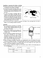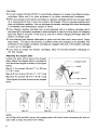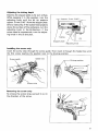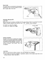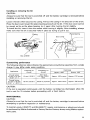
1
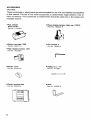
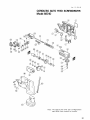
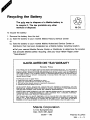
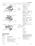
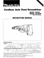
Cordless Auto Feed Screwdriver
MODEL 6831D
MODEL 6831DW
With Fast Charger
INSTRUCTION MANUAL
SPECIFICATIONS
68310
No load speed
Drywall screw size
(RPMI
4 mm x 25, 28. 32,40 mm
15/32"x l", 1-118".1.114". 1-9/16")
Battery Cartridge 1200
Voltage
12
v
2,000
Overall length
Net weight
340 mm ( 1 3.318")
2.1 kg (4.6Ibs)
Model DC1201 Fast Charger
I
Input
A.C. only 50 Hz - 60 Hz
I
output
I
Charging time
45 min. (For Battery cartridge 1200)
D.C. 9.6 V, 12 V
1 hour (For Batterv cartridae 1201)
~
Manufacturer reserves the right to change specifications w i t h o u t notice.
* Note: Specifications may differ f r o m country t o country.
WARNING: For your personal safety, READ and UNDERSTAND before using.
SAVE THESE INSTRUCTIONS FOR FUTURE REFERENCE.
IMPORTANT
SAFETY INSTRUCTIONS
(For All Tools)
WARNING: WHEN USING ELECTRIC TOOLS, BASIC SAFETY
PRECAUTIONS SHOULD ALWAYS BE FOLLOWED TO REDUCE
THE RISK OF FIRE, ELECTRIC SHOCK, AND PERSONAL
INJURY, INCLUDING THE FOLLOWING:
READ ALL INSTRUCTIONS.
1. KEEP WORK AREA CLEAN. Cluttered areas and benches invite injuries.
2. CONSIDER WORK AREA ENVIRONMENT. Don't use power tools in damp
or wet locations. Keep work area well lit. Don't expose power tools t o rain.
Don't use tool in presence of flammable liquids or gases.
3. KEEP CHILDREN AWAY. All visitors should be kept away from work area.
Don't let visitors contact tool or extension cord.
4. STORE IDLE TOOLS. When not in use, tools should be stored in dry, and high
or locked-up place - out of reach of children.
5. DON'T FORCE TOOL. It will do the job better and safer at the rate for which
it was intended.
6. USE RIGHT TOOL. Don't force small tool or attachment t o do the job of a
heavy-duty tool. Don't use tool for purpose not intended; for example, don't
use circular saw for cutting tree limbs or logs.
7 . DRESS PROPERLY. Don't wear loose clothing or jewelry. They can be caught
in moving parts. Rubber gloves and non-skid footwear are recommended
when working outdoors. Wear protective hair covering t o contain long hair.
8. USE SAFETY GLASSES. Also use face or dust mask if cutting operation is
dusty.
9. DON'T ABUSE CORD. Never carry tool by cord or yank it to disconnect from
receptacle. Keep cord from heat, oil, and sharp edges.
I O . SECURE WORK. Use clamps or a vise t o hold work. It's safer than using
your hand and it frees both hands t o operate tool.
11. DON'T OVERREACH. Keep proper footing and balance at all times.
12. MAINTAIN TOOLS WITH CARE. Keep tools sharp and clean for better and
safer performance. Follow instructions for lubricating and changing accessories. Inspect tool cords periodically and if damaged, have repaired by authorized service facility. Inspect extension cords periodically and replace if
damaged. Keep handles dry, clean, and free from oil and grease.
13. DISCONNECT TOOLS. When not in use, before servicing, and when changing accessories, such as blades, bits, cutters.
2
14. REMOVE ADJUSTING KEYS AND WRENCHES. Form habit of checking to
see that keys and adjusting wrenches are removed from tool before turning
it on.
15. AVOID UNINTENTIONAL STARTING. Don't carry tool with finger on switch.
Be sure switch is OFF when plugging in.
16. EXTENSION CORDS. Make sure your extension cord is in good condition.
When using an extension cord, be sure t o use one heavy enough t o carry
the current your product will draw. An undersized cord will cause a drop
in line voltage resulting in loss of power and overheating. Table 1 shows the
correct size to use depending on cord length and nameplate ampere rating.
If in doubt, use the next heavier gage. The smaller the gage number, the
heavier the cord.
TABLE 1 MINIMUM GAGE FOR CORD SETS
I
I
Total Length of Cord in Feet
0
~
25
I
26 - 50
Ampere Rating
More
Not More
Than
Than
0
6
10
12
-
-
6
10
12
16
I
51 - 100
I
101
-
150
A W G
18
18
16
14
16
16
16
12
;:
1
14
12
14
12
Not Recommended
17. OUTDOOR USE EXTENSION CORDS. When tool is used outdoors, use only
extension cords intended for use outdoors and so marked.
18. STAY ALERT. Watch what you are doing, use common sense. Don't operate
tool when you are tired.
19. CHECK DAMAGED PARTS. Before further use of the tool, a guard or other
part that is damaged should be carefully checked to determine that it will
operate properly and perform its intended function. Check for alignment of
moving parts, bindingof moving parts, breakage of parts, mounting, and any
other conditions that may affect its operation. A guard or other part that
is damaged should be properly repaired or replaced by an authorized service center unless otherwise indicated elsewhere in this instruction manual.
Have defective switches replaced by authorized service center. Don't use
tool if switch does not turn it on and off.
20. GUARD AGAINST ELECTRIC SHOCK. Prevent body contact with grounded
surfaces. For example; pipes, radiators, ranges, refrigerator enclosures.
21. REPLACEMENT PARTS. When servicing, use only identical replacement parts.
22. POLARIZED PLUGS. To reduce the risk of electric shock, this equipment has
a polarized plug (one blade is wider than the other). This plug will fit in a
polarized outlet only one way. If the plug does not fit fully in the outlet,
reverse the plug. If it still does not fit, contact a qualified electrician to install
the proper outlet. Do not change the plug in any way.
3
VOLTAGE WARNING: Before connecting the tool t o a power source (receptacle,
outlet, etc.) be sure the voltage supplied is the same as that specified on the
nameplate of the tool. A power source with voltage greater than that specified
for the tool can result in SERIOUS INJURY t o the user - as well as damage t o
the tool. If in doubt, DO NOT PLUG IN THE TOOL. Using a power source with
voltage less than the nameplate rating is harmful t o the motor.
4
IMPORTANT SAFETY INSTRUCTIONS
FOR CHARGER &
BATTERY CARTRIDGE
1.
SAVE THESE INSTRUCTIONS - This manual
Length of Cord (Feet)
AWG Size of Cord
25
18
50
100
150
18
18
16
9. Do not operate charger with damaged cord or plug - replace them immediately.
I O . Do not operate charger if it has received a sharp blow, been dropped, or otherwise damaged in any way; take it to a qualified serviceman.
11. Do not disassemble charger or battery cartridge; take it to a qualified
serviceman when service or repair is required. Incorrect reassembly may
result in a risk of electric shock or fire.
12. To reduce risk of electric shock, unplug charger from outlet before attempting any maintenance or cleaning. Turning off controls will not reduce this risk.
5
ADDITIONAL SAFETY RULES
FOR CHARGER & BATTERY CARTRIDGE
1. Do not charge Battery Cartridge when temperature is BELOW 10°C (5OOF)
or ABOVE 4OoC (104OF).
2. Do not attempt t o use a step-up transformer, an engine generator or DC power
receptacle.
3.Do not allow anything t o cover or clog the charger vents.
4. Always cover the battery terminals with the battery cover when the battery
cartridge is not used.
5. A battery short can cause a large current flow, overheating, possible burns
and even a breakdown.
(11 Do not touch the terminals with any conductive material.
(2)Avoid storing battery cartridge in a container with other metal objects such
as nails, coins, etc.
(3)Do not expose battery cartridge t o water or rain.
6. Do not store the tool and Battery Cartridge in locations where the temperature may reach or exceed 5OoC (122OF).
7. Do not incinerate the Battery Cartridge even if it is severely damaged or is
completely worn out. The battery cartridge can explode in a fire.
ADDITIONAL SAFETY RULES
1. Use only Makita genuine driver bits and drywall screw strips specified for this
tool.
2. Always be sure that the tool is switched off and unplugged before carrying
out any work on the tool.
3.Hold the tool firmly and squarely against the workpiece.
4. Be sure no one is below when using the tool in high locations.
5. Do not touch any metal parts of the tool t o prevent electrical shock if you
drive into a "live" wire.
6. Never lubricate the moving parts such as the feeder box. Malfunction of the
tool may result.
SAVE THESE INSTRUCTIONS.
6
Always switch off the tool before insertion
or removal of the battery cartridge.
To remove the battery cartridge, pull out the
set plate on the tool and grasp both sides
of the cartridge while withdrawing it from
the tool.
*To insert the battery cartridge, align the
tongue on the battery cartridge with the
groove in the housing and slip it into place.
Snap the set plate back into place. Be sure
to close the set plate fully before using the
tool to prevent the battery cartridge from
accidentally falling out of the tool.
Charging
Your new battery cartridge is not charged.
You will need t o charge it before use. Use
the fast charger Model DC1201 to charge
the battery cartridge.
Plug the fast charger into the proper A/C
voltage source The charging light will flash
in green color.
Insert the battery cartridge so that the plus
and minus terminals on the battery
cartridge are on the same sides as their
respective markings on the fast charger.
Insert the cartridge fully into the port so
that it rests on the charger port floor.
Battery cartridge
:artridge
charger
7
When the battery cartridge is inserted, the charging light color will change from green
to red and charging will begin. The charging light will remain lit steadily during chrging.
When charging is completed, the charging light color will change from red t o green and
a tone will sound steadily for about 5 seconds.
After charging, unplug the charger from the power source. Refer to the table below for
the charging time.
Fast charger
DC1201
Battery cartridge
1 2 0 1 or 1201A
Approx. 60 min.
1200
Approx. 45 min.
7
CAUTION:
The fast charger Model DC1201 is specifically designed to charge only Makita battery
cartridges. Never use it for other purposes or for other manufacturer's batteries.
When you charge a new battery cartridge or a battery cartridge which has not been used
for a long period of time, it may not accept a full charge. This is a normal condition and
does not indicate a problem. You can recharge the battery cartridge fully after discharging
it completely and recharging a couple of times.
If you charge a battery cartridge from a just-operated tool or a battery cartridge which
has been left in a location exposed to direct sunlight or heat for a long time, the charging
light may flash in red color. If this occurs, wait for a while. Charging will begin after the
battery cartridge cools.
If the charging light flashes alternately in green and red color and a tone sound "beep,
beep, beep,..." for about 20 seconds, a problem exists and charging is not possible. The
terminals on the charger or battery cartridge are clogged with dust or the battery cartridge
is worn out or damaged.
If you wish to charge t w o battery cartridges, allow 15 minutes between chargings on
the fast charger.
Adjusting the stopper plate
Loosen the bolts which secure the stopper
plate. Adjust the stopper plate in accordance
with the screw length as shown in the figure
below.
Fig. A - I : For screws 25 mm (1"1 or 28 mm
( 1- 118") long
/---
Stopper
Fig. A-2: For screws 32 mm (1-114") long
Fig. A-3: For screws 40 mm (1-9/16") long
Then tighten the bolts to secure the stopper
plate.
L.----Pins
Fig. A-I
/A I
T
Pin
Fig. A-2
Fig. A-3
NOTE:
As for Fig. A-2 and A-3, secure the stopper plate with both ends contacting the pins on
each side to keep the plate from tilting.
8
Adjusting the driving depth
Depress the stopper plate as far as it will go.
While keeping it in this position, turn the
adjusting knob until the bit tip projects
from the stopper plate.
approx. 5 mm (3/16")
Drive a trial screw. If the screw head projects
above the surface of the workpiece, turn the
adjusting knob in the Wdirection; if the
screw head is countersunk, turn the adjusting knob in the B direction.
Approx. 5 mm (3/16")
c
Casing
Stopper plate
Adjusting knob
Installing the screw strip
Insert the screw strip through the screw guide. Then insert it through the feeder box until
the first screw reaches the position next to the driving position.
Screw guide
p e d e r box
Driving position
Removing the screw strip
To remove the screw strip, just pull it out in
the direction of the arrow.
9
Carry hook
The carry hook is convenient for temporarily
hanging the tool. It can be installed on either
left or right side of the tool.
Hook
Switching ON and OFF
CAUTlON:
Before inserting the battery cartridge into the tool, always check to see that the switch
trigger actuates properly and returns to the "OFF" position when released.
To switch on, press the trigger.
To switch off, release the trigger.
Switch trigger
\
Driving operation
Switch on the tool by pressing the trigger.
Hold the tool squarely against the workpiece
and apply forward pressure to the tool. The
screw will be automatically carried to the
driving position and driven into the
workpiece.
CAUTION:
Do not fire the tool without screws. This will damage the workpiece.
If the feeder box becomes sluggish in operation, spray car wax (spray type wax) on its
sliding surfaces. Never lubricate it.
10
Installing or removing the bit
CAUTION:
Always be sure that the tool is switched off and the battery cartridge is removed before
installing or removing the bit.
Loosen the bolt which secures the casing. Pull out the casing in the direction of the arrow.
Press the dust cover toward the plane bearing and pull out the bit. If the dust cover cannot
be moved as far as the plane bearing, try it again after turning the bit slightly.
To install the bit, insert it into the socket while turning it slightly. After installing, always
make sure that the bit is securely held in place by trying t o pull it out.
7asing
Plane bearing
Dust cover
I
Hex wrench
Screwdriving performance
The following reference table indicates the approximate screwdriving capacities from a single
charge. It may differ under some condition.
1
Application
Thickness of
drywall
Foundation for
drywall
Fastenings
Battery 1200
Battery 1201
Drywall screw
4.0 mm x 25 mm
15/32" x 1")
12 mm (15/32")
Steel stud
0.5 mm (1/64")
thick
Approx. 430 screws
Approx. 610 screws
Drywall screw
4.0 m m x 4 0 mm
(5/32" x 1-9/16")
18 mm (23/32")
Wood or plywood
Approx. 230 screws
Approx. 330 screws
CAUTIO N:
If the tool is operated continuously until the battery cartridge has discharged, allow the
tool to rest for 15 minutes before proceeding with a fresh battery.
MAINTENANCE
CAUTlON:
Always be sure that the tool is switched off and the battery cartridge is removed before
attempting to perform inspection or maintenance.
To maintain product SAFETY and RELIABILITY, repairs, maintenance or adjustment should
be performed by Makita Authorized or Factory Service Centers, always using Makita replacement parts.
11
ACCESSORIES
CAUTION:
These accessories or attachments are recommendedfor use with your Makita tool specified
in this manual. The use of any other accessories or attachments might present a risk of
injury to persons. The accessories or attachments should be used only in the proper and
intended manner.
Fast charger
Model DC1201
Part No. 1 13126-0
Power display battery (High cap.) 1201A
Part No. 192407-5
QI
Battery cartridge 1200
Hex wrench 3
Part No. 192271-4
Part No. 783201-2
High capacity battery 1201
Part No. 192296-8
-
Battery cover
Phillips bit 2 - 117
Part No. 824421-0
Part No. A-1 2697
Plastic carrying case
Hook
Part No. 824421-0
Part No. 344056-6
12
Apr
- 12-'95
US
CORDLESS AUTO FEED SCREWDRIVER
Model 6831D
Note: The switch and other part configurations
may differ from country to country.
13
MODEL 6831D
;d,' "
DESCRIPTION
1
2
3
4
5
6
?
8
9
10
11
12
13
14
15
16
17
18
19
20
21
22
23
24
25
26
14
Apr.-12-'95
1
1
1
1
1
1
1
1
1
1
1
1
1
1
1
1
1
1
2
2
1
1
1
1
1
1
Name Plate
Housing Set (With Item 481
Switch Lever
Compression Spring 4
Swntch
Set Plate
Battery Holder
casmg
Shifter Pin
Dm1 Cover
Compression Spring 21
Phillips Bit 2 - 1 17
Feeder Box
Pin3
Stopper
Leaf Spring
nox cover
stopper Plate
Hex Socket Head Bolt M4x8
Hex Socket Head Bolt M4x8
Pan Head Screw M4x18 IWiIh Washerl
Flat Head Screw M3x5
Sleeve 4
Leaf s p m g
Ratchet Disc
Ratchet Wheel
'i\M
27
28
29
30
31
32
33
34
35
36
37
38
39
40
41
42
43
44
45
46
47
48
49
50
51
52
$FD
1
1
1
1
1
1
3
1
1
1
1
1
1
1
1
1
1
1
1
1
1
1
7
1
1
1
DESCRIPTION
Plate
Plane Beamg 1 4
Steel Ball 3 5
Spindle
Compression Spring 22
Helical Gear 55
PI" 4
Thrust Needle Bearing 821
Plane Bearing 8
Hex Socket Head Bolt M4x25 IWith Washer)
Knob 4 0
Compression Spring 12
Flat Washer 6
Countersunk Head Screw M4x12
Rubber Sleeve 1 0
Plane Bearing 5
Gear Complete 1 6 - 4 9
Flat Washer 5
Plane Bearing 5
Rubber Sleeve 1 0
DC Motor 12 V
Housing Set [With Item 21
Tapping scww 4 x 1 8
Makita Label
Battery 1200
Hand Strap
US
Recycling the Battery
The only way to dispose of a Makita battery is
to recycle it. The law prohibits any other
method of disposal.
I
Ni-Cd
1
To recycle the battery:
1. Remove the battery from the tool.
2. a). Take the battery to your nearest Makita Factory Service Center
or
b). Take the battery to your nearest Makita Authorized Service Center or
Distributor that has been designated as a Makita battery recycling location.
Call your nearest Makita Service Center or Distributor to determine the location
that provides Makita battery recycling. See your local Yellow Pages under
”Tools-Electric’
MAKITA LIMITED ONE YEAR WARRANTY
Warranty Policy
Every Makita tool is thoroughly inspected and tested before leaving the factory. It is warranted t o
be free of defects from workmanship and materials for the period of ONE YEAR from the date of
original purchase. Should any trouble develop during this one-year period, return the COMPLETE
tool, freight prepaid, to one of Makita’s Factory or Authorized Service Centers. If inspection shows
the trouble is caused by defective workmanship or material, Makita will repair (or at our option,
replace) without charge.
This Warranty does not apply where:
0 repairs have been made or attempted by others:
0 repairs are required because of normal wear and tear:
0 The tool has been abused, misused or improperly maintained;
0 alterations have been made to the tool.
IN NO EVENT SHALL MAKITA BE LIABLE FOR ANY INDIRECT, INCIDENTAL OR CONSEQUENTIAL DAMAGES FROM THE SALE OR USE OF THE PRODUCT. THIS DISCLAIMER
APPLIES BOTH DURING AND AFTER THE TERM O F THIS WARRANTY.
MAKITA DISCLAIMS LIABILITY FOR ANY IMPLIED WARRANTIES, INCLUDING IMPLIED
WARRANTIES O F “MERCHANTABILITY” AND “FITNESS FOR A SPECIFIC PURPOSE.”
AFTER THE ONE-YEAR TERM O F THIS WARRANTY.
This Warranty gives you specific legal rights, and you may also have other rights which vary from
state to state. Some states do not allow the exclusion or limitation of incidental or consequential
damages, so the above limitation or exclusion may not apply to you. Some states do not allow
limitation on how long an implied warranty lasts, so the above limitation may not apply to you.
Makita Corporation
3-11-8, Sumiyoshi-cho,
Anjo, Aichi 446 Japan
003097 - 062
PRINTED IN JAPAN
1995 - 5 - N