1
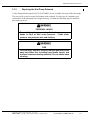
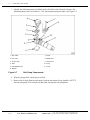
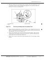
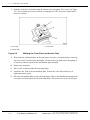
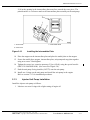
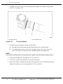
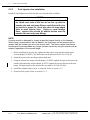
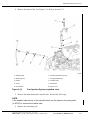
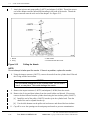
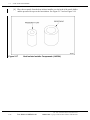
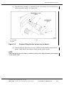
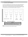
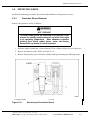
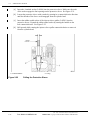
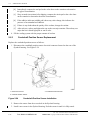
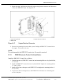
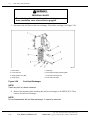
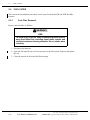
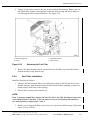
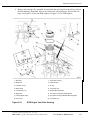
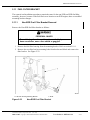
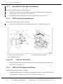
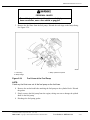
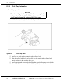
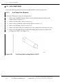
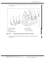
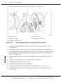
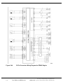
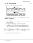
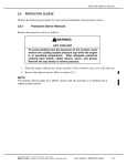
2
FUEL SYSTEM
Section
Page
2.1
INJECTOR UNIT PUMP ...........................................................................
2- 3
2.2
EGR INJECTOR UNIT PUMP ..................................................................
2-16
2.3
FUEL INJECTOR LINE ............................................................................
2-18
2.4
FUEL INJECTOR NOZZLE ......................................................................
2-22
2.5
EGR FUEL INJECTOR NOZZLE .............................................................
2-30
2.6
PROTECTIVE SLEEVE ...........................................................................
2-31
2.7
DDEC-ELECTRONIC CONTROL UNIT ...................................................
2-36
2.8
FUEL HEAT EXCHANGER ......................................................................
2-41
2.9
FUEL FILTER ...........................................................................................
2-44
2.10
FUEL FILTER HOUSING .........................................................................
2-47
2.11
FUEL FILTER BRACKET .........................................................................
2-51
2.12
FUEL PUMP .............................................................................................
2-54
2.13
FUEL PUMP DRIVE .................................................................................
2-58
2.14
FUEL SYSTEM INSPECTION .................................................................
2-62
2.A
ADDITIONAL INFORMATION ..................................................................
2-71
(Rev. 3/04)
2-2
From Bulletin 2–MBE4000–06
All information subject to change without notice.
6SE412 0403 Copyright © 2006 DETROIT DIESEL CORPORATION
MBE4000 SERVICE MANUAL
2.1
INJECTOR UNIT PUMP
A special tool is required for this procedure.
2.1.1
Injector Unit Pump Removal
Remove the injector unit pump as follows:
1. Remove the engine trim cover.
2. Unscrew the fuel filter cap. See Figure 2-1.
1. Fuel Filter Cap
3. Filter Element
2. O-ring
Figure 2-1
Main Fuel Filter (exploded view)
NOTE:
Unscrewing the fuel filter cap releases pressure in the fuel system, causing fuel to flow
through the return lines and back into the tank.
All information subject to change without notice.
(Rev. 3/04)
6SE412 0403 Copyright © 2006 DETROIT DIESEL CORPORATION
From Bulletin 2–MBE4000–06
2-3
2.1
INJECTOR UNIT PUMP
3. Disconnect the engine wiring harness from the injector unit pump. See Figure 2-2.
1. Engine Wiring Harness
3. Terminal Screw
2. Terminal
4. Injector Unit Pump
Figure 2-2
Unit Pump Electrical Wires
PERSONAL INJURY
To avoid injury from the sudden release of a high-pressure
hose connection, wear a face shield or goggles.
4. Remove the high-pressure fuel injector line. Refer to section 2.3.1.
5. Disconnect the fuel line at the fuel gallery inlet. Have a suitable container ready to catch
any fuel that comes out of the cylinder block or fuel line.
(Rev. 3/04)
2-4
From Bulletin 2–MBE4000–06
All information subject to change without notice.
6SE412 0403 Copyright © 2006 DETROIT DIESEL CORPORATION
MBE4000 SERVICE MANUAL
6. Drain fuel from the engine through the fuel gallery outlet on the return lines. See Figure
2-3.
1. High-Pressure Fuel Injector Line
4. Banjo Fitting
2. Hollow-Core Banjo Bolt
5. Pressure Limiting Valve
3. Seal Rings
6. Fuel Gallery Outlet
Figure 2-3
Drain Fuel from the Return Lines
[a]
Remove the outer banjo bolt and fitting from the pressure limiting valve. Discard
the seal rings.
[b]
Have a suitable container ready to catch any fuel that runs out of the cylinder block
or return lines.
[c]
Unscrew the threaded end of the pressure limiting valve from the fuel gallery outlet.
[d]
Remove the inner banjo fitting from the pressure limiting valve. Discard the seal
rings.
[e]
Mark the fasteners with a paint pen for ease of installation.
[f]
Clean out the fuel gallery outlet with compressed air.
NOTE:
This step is necessary to prevent fuel from contaminating the engine oil in the block.
7. Remove the end cover from the lower right side of the flywheel housing, then attach
the engine barring tool (J-46392).
All information subject to change without notice.
(Rev. 3/04)
6SE412 0403 Copyright © 2006 DETROIT DIESEL CORPORATION
From Bulletin 2–MBE4000–06
2-5
2.1
INJECTOR UNIT PUMP
EYE INJURY
To avoid injury from flying parts when working with
components under spring tension, wear adequate eye
protection (face shield or safety goggles).
8. Carefully loosen the injector unit pump mounting bolts about 6 mm (1/4 inch), but do not
remove them yet. See Figure 2-4.
1. Mounting Bolt
Figure 2-4
2. Head of Unit Pump
Loosen the Mounting Bolts
9. Using the engine barring tool (J-46392), rotate the crankshaft until the cam pushes the
unit pump upwards.
(Rev. 3/04)
2-6
From Bulletin 2–MBE4000–06
All information subject to change without notice.
6SE412 0403 Copyright © 2006 DETROIT DIESEL CORPORATION
MBE4000 SERVICE MANUAL
NOTICE:
If the injector unit pump doesn't come out easily, do not try
to pry up on the body of the pump. This will damage it.
10. If the injector unit pump is locked up, or frozen, in its seat, release it using the blade
of a small screwdriver under the flange where the mounting bolt attaches. See arrow
in Figure 2-5.
Figure 2-5
Releasing a Locked-up Pump
All information subject to change without notice.
(Rev. 3/04)
6SE412 0403 Copyright © 2006 DETROIT DIESEL CORPORATION
From Bulletin 2–MBE4000–06
2-7
2.1
INJECTOR UNIT PUMP
11. Remove both mounting bolts completely. Carefully pull the unit pump out of the cylinder
block. See Figure 2-6.
1. Mounting Bolt
3. Cylinder Block
2. Unit Pump
Figure 2-6
Removing the Unit Pump
12. Check the injector unit pump for fuel leakage at the solenoid. If leakage is
found, refer to section 2.1.2.
13. Check the injector unit pump for wear or damage. If any is found replace unit
pump. Refer to section 2.1.3.
14. Remove and discard the two O-rings on the unit pump shaft.
(Rev. 3/04)
2-8
From Bulletin 2–MBE4000–06
All information subject to change without notice.
6SE412 0403 Copyright © 2006 DETROIT DIESEL CORPORATION
MBE4000 SERVICE MANUAL
2.1.2
Repairing the Unit Pump Solenoid
A Unit Pump Solenoid repair kit (P/N: 0120740001) is now available for repair of the unit pump.
This service kit is used to repair fuel leakage at the solenoid. For this type of complaint, total
replacement of the unit pump is no longer necessary. Perform the following steps to install the
unit pump repair kit.
PERSONAL INJURY
To avoid injury from penetrating fluids, do not put your
hands in front of fluid under pressure. Fluids under
pressure can penetrate skin and clothing.
FIRE
To avoid injury from fire, keep all potential ignition sources
away from diesel fuel, including open flames, sparks, and
electrical resistance heating elements. Do not smoke when
refueling.
All information subject to change without notice.
(Rev. 3/04)
6SE412 0403 Copyright © 2006 DETROIT DIESEL CORPORATION
From Bulletin 2–MBE4000–06
2-9
2.1
INJECTOR UNIT PUMP
1. Identify the failed unit pump and failure mode (fuel leak at the solenoid). Remove the
failed unit pump. Refer to section 2.1.1 for unit pump removal procedure. See Figure 2-7.
1. Stop Plate
7. Screw
2. Unit Pump
8. Model Plate
3. Anchor Plate
9. Cross Piece
4. Seal
10. O-ring
5. Intermediate Plate
11. O-ring
6. Magnet
Figure 2-7
Unit Pump Components
2. Wipe the pump clean, removing excess fuel.
3. Remove the O-rings from the unit pump. Push the unit pump O-ring installer (J-45373)
onto the unit pump. This will prevent dirt from entering the unit pump holes.
(Rev. 3/04)
2-10
From Bulletin 2–MBE4000–06
All information subject to change without notice.
6SE412 0403 Copyright © 2006 DETROIT DIESEL CORPORATION
MBE4000 SERVICE MANUAL
4. Mark the position of the intermediate plate in relation to the unit pump body (See arrow
A of Figure 2-8) and rest the unit pump on the stop plate. Use a pencil or scriber for
marking. Do not use any stamping tools.
1. Intermediate Plate
3. Special Torx Bit
2. Screw
Figure 2-8
Removing the Magnet and Intermediate Plate
5. Remove all traces of paint from screw heads. Remove screws using the special torx bit
(DDC P/N: 9045890210/00) and lift off the magnet together with the intermediate plate
and model plate. (See arrow B of Figure 2-8).
6. Remove the intermediate plate and the model plate from the magnet. Wipe clean the
sealing surface on the magnet, removing any excess fuel. Clean the model plate and
remove paint from the screw heads contact area.
7. Remove the two spacer seals and clean the intermediate plate. Do not damage sealing
surfaces.
All information subject to change without notice.
(Rev. 3/04)
6SE412 0403 Copyright © 2006 DETROIT DIESEL CORPORATION
From Bulletin 2–MBE4000–06
2-11
2.1
INJECTOR UNIT PUMP
8. Mark the cross piece and anchor plate in relation to the unit pump. (See arrow C of Figure
2-9). Use a marker; do not use a scriber or stamping tool. The cross piece should not be
moved or twisted.
1. Unit Pump
3. Cross Piece
2. Anchor Plate
Figure 2-9
Marking the Cross Piece and Anchor Plate
9. Wipe clean the sealing surfaces on the unit pump, cross piece, and anchor plate, removing
any excess fuel. Clean the parts thoroughly. Do not remove the paint on the unit pump; it
is used as a reference point for the intermediate plate assembly.
10. Remove the stop plate.
11. Place a new stop plate under the unit pump body.
12. Install the new seals in the intermediate plate. Protect the seals with a thin layer of
high-temperature grease.
13. Place the intermediate plate on the unit pump body. Observe the identification mark on the
cross piece and anchor plate for the unit pump body. The cutouts (see arrows D of Figure
(Rev. 3/04)
2-12
From Bulletin 2–MBE4000–06
All information subject to change without notice.
6SE412 0403 Copyright © 2006 DETROIT DIESEL CORPORATION
MBE4000 SERVICE MANUAL
2-10) at the opening in the intermediate plate must face towards the cross piece. The
painted surface is a reference mark to the intermediate plate assembly on the unit pump.
1. Anchor Plate
3. Intermediate Plate
2. Cross Piece
Figure 2-10
Installing the Intermediate Plate
14. Place the magnet on the intermediate plate and place the model plate on the magnet.
15. Secure the model plate, magnet, intermediate plate, unit pump and stop plate together
using new screws. Hand tighten.
16. Tighten the screws in a crosswise pattern to 5 N·m (4 lb·ft), using the special torx bit
(DDC P/N: 9045890210/00). (See arrow B of Figure 2-8).
17. Push the unit pump O-ring installer (J-45373) onto the unit pump.
18. Install new O-rings on the unit pump and install the unit pump in the engine.
Refer to section 2.1.3 for installation procedures.
2.1.3
Injector Unit Pump Installation
Install the injector unit pump as follows:
1. Lubricate two new O-rings with a light coating of engine oil.
All information subject to change without notice.
(Rev. 3/04)
6SE412 0403 Copyright © 2006 DETROIT DIESEL CORPORATION
From Bulletin 2–MBE4000–06
2-13
2.1
INJECTOR UNIT PUMP
2. Install the two new O-rings on the unit pump shaft using the Unit Pump O-ring installer
(J-45373). See Figure 2-11.
1. Inner (larger) O-ring
Figure 2-11
2. Outer (smaller) O-ring
O-ring Installation
3. Install the injector unit pump into the cylinder block.
[a]
Insert the injector unit pump into the mounting hole in the cylinder block.
[b]
Use light hand pressure to push in the unit pump until it seats, about 4 mm (0.16
inch). If it won't seat easily, rotate the crankshaft until the unit pump seats.
NOTE:
Use the bolt mounting holes on the engine as a guide for positioning the injector pump.
4. Install the mounting bolts, and tighten to 65 N·m (48 lb·ft).
5. Connect the engine wiring harness to the injector unit pump.
6. Remove the engine cranking tool and replace the inspection cover on the flywheel housing.
Tighten the inspection cover mounting bolts to 25 N·m (18 lb·ft).
(Rev. 3/04)
2-14
From Bulletin 2–MBE4000–06
All information subject to change without notice.
6SE412 0403 Copyright © 2006 DETROIT DIESEL CORPORATION
MBE4000 SERVICE MANUAL
PERSONAL INJURY
To avoid injury from the sudden release of a high-pressure
hose connection, wear a face shield or goggles.
7. Connect the fuel line at the fuel gallery inlet. Tighten the fitting to 50 N·m (37 lb·ft).
8. Install the fuel lines and pressure limiting valve on the fuel gallery outlet. Tighten all
fasteners to 50 N·m (37 lb·ft).
[a]
Install the inner banjo fitting, and two new seal rings, on the pressure limiting valve,
as marked on removal.
[b]
Install the threaded end of the pressure limiting valve in the fuel gallery outlet. When
the valve is firmly seated, tighten to 50 N·m (37 lb·ft).
[c]
Install the outer banjo fitting, again with two new seal rings, on the banjo bolt, as
marked on removal.
[d]
Install the banjo bolt on the pressure limiting valve and tighten to 40-50 N·m (30-37
lb·ft).
9. Install the fuel filter cap. Inspect the O-ring in the fuel filter and replace it if worn. Tighten
the cap nut to 25 N·m (18 lb·ft).
10. Install the high-pressure fuel injector line. Refer to section 2.3.2.
PERSONAL INJURY
Diesel engine exhaust and some of its constituents are
known to the State of California to cause cancer, birth
defects, and other reproductive harm.
□ Always start and operate an engine in a well ventilated
area.
□ If operating an engine in an enclosed area, vent the
exhaust to the outside.
□ Do not modify or tamper with the exhaust system or
emission control system.
11. Prime the fuel system. Refer to section 11.1.5.
12. Start the engine and check for leaks. Tighten connections as needed.
13. Install the engine trim cover.
All information subject to change without notice.
(Rev. 3/04)
6SE412 0403 Copyright © 2006 DETROIT DIESEL CORPORATION
From Bulletin 2–MBE4000–06
2-15
2.2
EGR INJECTOR UNIT PUMP
2.2
EGR INJECTOR UNIT PUMP
The removal and installation of the EGR injector unit pump is the same as the non-EGR engine;
however, the EGR injector unit pump must be programmed to coordinate with the DDEC-ECU
(formerly PLD-MR).
2.2.1
EGR Injector Unit Pump Programming
When replacing and before installing a new EPA 04 EGR unit pump, the unit pump identification
code number must be programmed into the DDEC-ECU (PLD-MR). Perform the following
procedures to insert this code into the unit pump:
NOTE:
On the top surface of each EGR unit pump, there is a unit pump identification code
number. This is the number that is programmed into the DDEC-ECU (formerly PLD-MR)
to coordinate the operation of the unit pumps. See Figure 2-12.
1. Injector Unit Pump
Figure 2-12
2. Injector Unit Pump Identification Number
Injector Unit Pump Identification Number
1. Consult the minidiag2 manual for service routines.
2. Select routine number 006 – Pump Line Nozzle Change.
3. Enter the unit pump identification Number found on the top of the unit pump.
4. Press enter.
5. Press double-arrow back key.
(Rev. 3/04)
2-16
From Bulletin 2–MBE4000–06
All information subject to change without notice.
6SE412 0403 Copyright © 2006 DETROIT DIESEL CORPORATION
MBE4000 SERVICE MANUAL
6. Turn off key and unplug minidiag2.
7. Install the unit pump. Refer to section 2.1.3.
All information subject to change without notice.
(Rev. 3/04)
6SE412 0403 Copyright © 2006 DETROIT DIESEL CORPORATION
From Bulletin 2–MBE4000–06
2-17
2.3
FUEL INJECTOR LINE
2.3
FUEL INJECTOR LINE
Perform the following procedures for removal and installation of the fuel injector line. The
following procedures will also explain how to repair a leaking or broken fuel injector line.
2.3.1
Fuel Injector Line Removal
Remove the fuel injector line as follows:
FIRE
To avoid injury from fire, keep all potential ignition sources
away from diesel fuel, including open flames, sparks, and
electrical resistance heating elements. Do not smoke when
refueling.
FIRE
To avoid injury from fire caused by heated diesel-fuel
vapors:
□ Keep those people who are not directly involved in
servicing away from the engine.
□ Stop the engine immediately if a fuel leak is detected.
□ Do not smoke or allow open flames when working on
an operating engine.
□ Wear adequate protective clothing (face shield,
insulated gloves and apron, etc.).
□ To prevent a buildup of potentially volatile vapors, keep
the engine area well ventilated during operation.
1. Remove both engine trim covers and identify the leaking line.
NOTE:
The MBE4000 engine has individual heads for each cylinder. To remove the injector line
from one cylinder, follow these procedures step by step. To remove all the injector lines,
repeat each step in these instructions, as applicable, for all six cylinders.
NOTE:
Remove only leaking lines. Do not attempt to service good lines that are not leaking.
2. Remove the cylinder head cover for each cylinder head, as required. Refer to section 1.1.1.
(Rev. 3/04)
2-18
From Bulletin 2–MBE4000–06
All information subject to change without notice.
6SE412 0403 Copyright © 2006 DETROIT DIESEL CORPORATION
MBE4000 SERVICE MANUAL
3. From the topside of the engine use the injector line torque wrench adaptor (J-45062) and
loosen the injector line nut at the transfer tube. See Figure 2-13.
1. Injector Line Nut, Unit Pump Fitting
3. Injector Line Nut, Transfer Tube Fitting
2. Injector Line
4. Thrust Bolt
Figure 2-13
High-Pressure Injector Line Removal / Installation
NOTICE:
Do not crimp or nick the injector line tubing. Overbending
the tubing can close the passage or restrict the flow of fuel.
Nicks can cause weak spots that could lead to injector line
failure.
PERSONAL INJURY
To avoid injury from the sudden release of a high-pressure
hose connection, wear a face shield or goggles.
4. Using wrench adaptor (J-46371) loosen the injection line at the injector unit pump.
Remove and discard the injector line.
5. Remove the transfer tube. Use the wrench adaptor (J-45063) to loosen the thrust bolt.
NOTE:
Discard the failed high-pressure fuel line and transfer tube. Do not re-use them!
All information subject to change without notice.
(Rev. 3/04)
6SE412 0403 Copyright © 2006 DETROIT DIESEL CORPORATION
From Bulletin 2–MBE4000–06
2-19
2.3
FUEL INJECTOR LINE
2.3.2
Fuel Injector Line Installation
Install the fuel high pressure fuel line and a new transfer tube as follows:
NOTICE:
New injector lines are supplied ready for installation. If
the flared cone ends of the line do not line up with the
transfer-tube and unit-pump fittings, carefully bend the line
by hand for a proper fit. Never use pliers or sharp-edged
tools to bend injector lines. Doing so could damage
them. Injector lines should fit without tension over the
transfer-tube and unit-pump fittings.
NOTE:
A torque wrench is designed to a apply a specified torque directly on the fastener.
When using a torque wrench with an adaptor, the final torque on the fastener will be
greater than the number you set on the wrench itself. The torque values listed below
are designed to accommodate any torque variation caused by using the wrench with an
adaptor, regardless of the wrench length.
1. Before installing the injector line, tighten the thrust bolt, using the thrust bolt torque
wrench adaptor, (J-45063). The final torque on the bolt must be 45 N·m (33 lb·ft ).
2. Install the injector line nuts finger-tight at both ends.
3. Using the injector line torque wrench adaptor, (J-45062), tighten the injector line nut at the
transfer tube and using wrench adaptor (J-46371) tighten the injector line nut at the unit
pump. The final torque on the injector line nuts must be 30 N·m (22 lb·ft).
4. Install the cylinder head cover(s), as removed. Refer to section 1.1.2.
5. Prime the fuel system. Refer to section 11.1.5.
(Rev. 3/04)
2-20
From Bulletin 2–MBE4000–06
All information subject to change without notice.
6SE412 0403 Copyright © 2006 DETROIT DIESEL CORPORATION
MBE4000 SERVICE MANUAL
PERSONAL INJURY
Diesel engine exhaust and some of its constituents are
known to the State of California to cause cancer, birth
defects, and other reproductive harm.
□ Always start and operate an engine in a well ventilated
area.
□ If operating an engine in an enclosed area, vent the
exhaust to the outside.
□ Do not modify or tamper with the exhaust system or
emission control system.
6. Run the engine and check for leaks. Tighten the connections as needed.
7. Shut down the engine and install the remaining components.
All information subject to change without notice.
(Rev. 3/04)
6SE412 0403 Copyright © 2006 DETROIT DIESEL CORPORATION
From Bulletin 2–MBE4000–06
2-21
2.4
FUEL INJECTOR NOZZLE
2.4
FUEL INJECTOR NOZZLE
Perform the following procedures for removal and installation of the fuel injector nozzle.
2.4.1
Fuel Injector Nozzle Removal
Remove the fuel injector nozzle as follows:
1. Remove the engine trim covers.
NOTE:
The MBE4000 engine has individual heads for each cylinder. To remove the injector
nozzle for one cylinder, do these procedures step by step. To remove all the injector
nozzles, repeat each step in these instructions, as applicable, for all six cylinders.
2. Remove the cylinder head cover for each cylinder head, as required. Refer to section 1.1.1.
3. Remove the charge-air manifold. Refer to section 6.1.1.
FIRE
To avoid injury from fire, keep all potential ignition sources
away from diesel fuel, including open flames, sparks, and
electrical resistance heating elements. Do not smoke when
refueling.
FIRE
To avoid injury from fire caused by heated diesel-fuel
vapors:
□ Keep those people who are not directly involved in
servicing away from the engine.
□ Stop the engine immediately if a fuel leak is detected.
□ Do not smoke or allow open flames when working on
an operating engine.
□ Wear adequate protective clothing (face shield,
insulated gloves and apron, etc.).
□ To prevent a buildup of potentially volatile vapors, keep
the engine area well ventilated during operation.
(Rev. 3/04)
2-22
From Bulletin 2–MBE4000–06
All information subject to change without notice.
6SE412 0403 Copyright © 2006 DETROIT DIESEL CORPORATION
MBE4000 SERVICE MANUAL
4. Remove the injector line. See Figure 2-14. Refer to section 2.3.1.
1. Retaining Bolt
6. Constant-Throttle End Cover
2. Tensioning Arm
7. O-ring (transfer tube)
3. Nozzle
8. Transfer Tube
4. O-ring
9. Thrust Bolt
10. Injector Line
5. Heat Isolator
Figure 2-14
Fuel Injection System (exploded view)
5. Remove the thrust bolt and the transfer tube. Discard the old O-ring.
NOTE:
If the transfer tube is stuck in the cylinder head, use the injector unit pump puller
(J–46375) to remove the transfer tube.
6. Remove the tensioning arm.
All information subject to change without notice.
(Rev. 3/04)
6SE412 0403 Copyright © 2006 DETROIT DIESEL CORPORATION
From Bulletin 2–MBE4000–06
2-23
2.4
FUEL INJECTOR NOZZLE
7. Attach the injector unit pump puller (J-46375) and adaptor (J-46384). Thread the narrow
end of the adaptor onto the internal M8 threading in the head of the nozzle. Thread the
impact extractor onto the wide end of the adaptor. See Figure 2-15.
1. Nozzle
3. Heat Isolator
2. O-ring
4. Constant-Throttle End Cover
Figure 2-15
Pulling the Nozzle
NOTE:
Do not attempt to take apart the nozzle. If there is a problem, replace the nozzle.
8. Using the impact extractor (J-46375), remove the nozzle from the cylinder head. Discard
the O-ring and the heat isolator.
NOTICE:
Pull the nozzle straight out of the cylinder head. Do not twist it,
turn it, or use pliers. This could damage the nozzle.
9. Remove the impact extractor (J-46375) and adaptor (J-46384) from the nozzle.
10. Remove the O-ring and heat isolator from the nozzle holder and discard. If necessary,
remove the heat isolator from the cylinder head using the heat isolator puller (J-46933).
[a]
Install the end of the puller (J-46933) into the tip in the cylinder head. Turn the
shaft of the tool to expand into the tip.
[b]
Use the slide hammer on the puller tool and remove and discard the heat isolator.
11. Cap off or cover the openings on the unit pump and nozzle to prevent contamination.
(Rev. 3/04)
2-24
From Bulletin 2–MBE4000–06
All information subject to change without notice.
6SE412 0403 Copyright © 2006 DETROIT DIESEL CORPORATION
MBE4000 SERVICE MANUAL
2.4.2
Fuel Injector Nozzle Installation
Install the fuel injector nozzle as follows:
1. Using a dial caliper, measure the length, of the tensioning arm M10 retaining bolt, from
the end of the bolt to the bottom of the flange. See Figure 2-16. The acceptable lengths
are listed in Table 2-1. Replace any bolt which does not meet these specifications.
1. Dial Caliper
3. Bottom of Flange
2. End of Retaining Bolt
Figure 2-16
Measuring the Tensioning Arm Retaining Bolt
Description
Length, mm (in.)
Shaft length when new
90.0 mm (3.54 inches)
Maximum shaft length
91.0 mm (3.58 inches)
Table 2-1
M10 Tensioning Arm Retaining Bolt, Length
2. Lubricate a new nozzle O-ring with a light coating of engine oil and install it on the nozzle.
3. Using the heat isolator installer (J-46384), press the new heat isolator onto the nozzle.
[a]
Position the new heat isolator over the nozzle.
All information subject to change without notice.
(Rev. 3/04)
6SE412 0403 Copyright © 2006 DETROIT DIESEL CORPORATION
From Bulletin 2–MBE4000–06
2-25
2.4
FUEL INJECTOR NOZZLE
[b]
Place the receptacle from the heat isolator installer over the head of the nozzle holder
and the pressure-fit cap over the heat isolator. See Figure 2-17 and see Figure 2-18.
Figure 2-17
Heat Isolator Installer Components (J-46384)
(Rev. 3/04)
2-26
From Bulletin 2–MBE4000–06
All information subject to change without notice.
6SE412 0403 Copyright © 2006 DETROIT DIESEL CORPORATION
MBE4000 SERVICE MANUAL
[c]
Place this entire assembly in a vise and close the vise enough to pressure-fit the heat
isolator around the nozzle. See Figure 2-18.
1. Heat Isolator
3. Vise
2. Nozzle
Figure 2-18
[d]
Pressure-Fitting the Heat Isolator onto the Nozzle
Open the vise and remove the two parts of the heat isolator installer from the nozzle
holder. Check that the heat isolator is firmly pressed onto the nozzle.
NOTE:
Take care that the nozzle holder is installed correctly and is aligned properly with respect
to the transfer tube.
All information subject to change without notice.
(Rev. 3/04)
6SE412 0403 Copyright © 2006 DETROIT DIESEL CORPORATION
From Bulletin 2–MBE4000–06
2-27
2.4
FUEL INJECTOR NOZZLE
4. Install the nozzle in the cylinder head. Align the notch in the tensioning arm with the pin
on the top of the nozzle.See arrow in Figure 2-19.
1. Injector Line Fitting
7. Retaining Bolt
2. Thrust Bolt
8. Tensioning Arm
3. O-ring (transfer tube)
9. End Cover (Constant-Throttle)
4. Transfer Tube
10. Heat Isolator
5. Nozzle
11. Protective Sleeve
6. O-ring (nozzle)
Figure 2-19
Positioning the Nozzle
5. Install the retaining bolt in the tensioning arm. Tighten the bolt 50 N·m (37 lb·ft).
NOTE:
The tensioning arm insures the correct positioning of the nozzle.
(Rev. 3/04)
2-28
From Bulletin 2–MBE4000–06
All information subject to change without notice.
6SE412 0403 Copyright © 2006 DETROIT DIESEL CORPORATION
MBE4000 SERVICE MANUAL
6. Lubricate a new transfer-tube O-ring with a light coating of engine oil and install it on the
transfer tube.
NOTE:
Do not tighten the thrust bolt until after the tensioning arm has been fully tightened to
the correct torque value.
7. Install the transfer tube in the cylinder head. Tighten the thrust bolt 45 N·m (33 lb·ft).
8. Install the injector line. Refer to section 2.3.2.
9. Install the charge-air manifold. Refer to section 6.1.2.
10. Install the cylinder head cover(s), as removed. Refer to section 1.1.2.
11. Install the engine trim covers.
All information subject to change without notice.
(Rev. 3/04)
6SE412 0403 Copyright © 2006 DETROIT DIESEL CORPORATION
From Bulletin 2–MBE4000–06
2-29
2.5
2.5
EGR FUEL INJECTOR NOZZLE
EGR FUEL INJECTOR NOZZLE
The removal and installation procedures remain the same for the non-EGR and EGR fuel injector
nozzle. There are minor differences in the injector nozzles for the two engines. The EPA 98
engine uses injector nozzle #1070 until engine series number 744382 and from engine series
number 744383 on, the 98 engine uses injector nozzle #1281. The EPA 04 EGR engine now has
two injector nozzles – one for low HP and the other for high HP. Each injector nozzle is stamped
with a production number for the EPA 98 and EPA 04 engines. See Figure 2-20.
Figure 2-20
Injector Nozzle Identification
NOTICE:
EPA 98 injector nozzles may not be used in an EPA 04 EGR
engine. Verify correct nozzle before insertion into engine.
NOTE:
There is no fuel return hole on EPA 04 EGR fuel nozzles.
(Rev. 3/04)
2-30
From Bulletin 2–MBE4000–06
All information subject to change without notice.
6SE412 0403 Copyright © 2006 DETROIT DIESEL CORPORATION
MBE4000 SERVICE MANUAL
2.6
PROTECTIVE SLEEVE
Perform the following procedures for removal and installation of the protective sleeve.
2.6.1
Protective Sleeve Removal
Remove the protective sleeve as follows:
HOT COOLANT
To avoid scalding from the expulsion of hot coolant, never
remove the cooling system pressure cap while the engine
is at operating temperature. Wear adequate protective
clothing (face shield, rubber gloves, apron, and boots).
Remove the cap slowly to relieve pressure.
1. Drain the engine coolant into a clean container. If the coolant is clean, save it for later use.
2. Remove the injector nozzle. Refer to section 2.4.1.
3. Remove the protective sleeve from the cylinder head by performing the following steps:
1. Protective Sleeve
Figure 2-21
2. O-ring
Removing the Protective Sleeve
All information subject to change without notice.
(Rev. 3/04)
6SE412 0403 Copyright © 2006 DETROIT DIESEL CORPORATION
From Bulletin 2–MBE4000–06
2-31
2.6
PROTECTIVE SLEEVE
[a]
Insert the 4-toothed socket (J-46186) into the protective sleeve. Make sure the teeth
of the socket engage the four openings on the protective sleeve. See Figure 2-21.
[b]
Loosen the protective sleeve with a ratchet by turning in a counterclockwise direction
until the threads of the sleeve are disengaged from the cylinder head.
[c]
Insert the rubber-ended socket of the injector sleeve puller (J-46381) into the
protective sleeve. Expand the rubber-ended socket by turning the handle on the
tool counterclockwise. See Figure 2-22
[d]
Pull upward while rotating the injector sleeve puller counterclockwise to remove it
from the cylinder head.
1. Protective Sleeve
Figure 2-22
2. O-ring
Pulling the Protective Sleeve
(Rev. 3/04)
2-32
From Bulletin 2–MBE4000–06
All information subject to change without notice.
6SE412 0403 Copyright © 2006 DETROIT DIESEL CORPORATION
MBE4000 SERVICE MANUAL
4. Remove the O-ring from the cylinder head. See Figure 2-23.
1. Nozzle
3. Protective Sleeve
2. Heat Isolator
4. O-ring
Figure 2-23
Removing the O-ring
NOTE:
Replace the O-ring whenever the protective sleeve is removed.
2.6.2
Protective Sleeve Installation
Install the protective sleeve as follows:
1. Clean the sealing surfaces of the protective sleeve and the cylinder head.
2. Lubricate the new O-ring with a light coating of engine oil. Install the O-ring in the
cylinder head.
3. Install the protective sleeve into the cylinder head. Using the 4-toothed socket (J-46186)
and turning in a clockwise direction, torque the protective sleeve to 45 N·m (33 lb·ft).
4. Install the nozzle. Refer to section 2.4.2.
Use Detroit Diesel POWER Trac® 3–way Coolant Test Strips to measure nitrite and glycol
concentrations. If the test indicates the coolant is acceptable reuse the coolant. If the test indicates
the coolant is not within specifications, discard the coolant and replace with new.
5. Check the coolant inhibitor level as follows:
[a]
Dip the test strip into the coolant for one second, then remove it. Shake the strip
vigorously to remove excess liquid.
All information subject to change without notice.
(Rev. 3/04)
6SE412 0403 Copyright © 2006 DETROIT DIESEL CORPORATION
From Bulletin 2–MBE4000–06
2-33
2.6
PROTECTIVE SLEEVE
[b]
Immediately compare the end pad to the color chart on the container to determine
the glycol concentration.
[c]
Sixty-seconds (one minute) after dipping, compare the nitrite pad to the color chart
on the container to determine the nitrite concentration.
[d]
If the additive indicator (middle pad) shows any color change, this indicates the
presence of an unauthorized inhibitor.
[e]
If there is any doubt about the quality of the coolant, change the coolant.
[f]
After each use, replace and tighten the cap on the test strip container. Discard any test
strips that have turned light pink or tan in color.
6. Fill the cooling system with the proper amount of coolant.
2.6.3
Crankshaft Position Sensor Replacement
Replace the crankshaft position sensor as follows:
1. Disconnect the crankshaft position sensor electrical connector located on the rear of the
flywheel housing. See Figure 2-24.
1. Electrical Connector
3. Crankshaft Position Sensor
2. Camshaft Position Sensor
Figure 2-24
Crankshaft Position Sensor Installation
2. Remove the sensor from the access hole in the flywheel housing.
3. Install a new sensor in the flywheel housing. Push the sensor in until it is fully seated.
(Rev. 3/04)
2-34
From Bulletin 2–MBE4000–06
All information subject to change without notice.
6SE412 0403 Copyright © 2006 DETROIT DIESEL CORPORATION
MBE4000 SERVICE MANUAL
4. Connect the electrical connector.
NOTE:
Be sure that the correct electrical connector is connected to the sensor.
All information subject to change without notice.
(Rev. 3/04)
6SE412 0403 Copyright © 2006 DETROIT DIESEL CORPORATION
From Bulletin 2–MBE4000–06
2-35
2.7
DDEC-ELECTRONIC CONTROL UNIT
2.7
DDEC-ELECTRONIC CONTROL UNIT
Perform the following procedures for removal and installation of the DDEC-ECU.
2.7.1
DDEC-Electronic Control Unit Removal
Remove the DDEC-ECU as follows:
1. Disconnect the batteries.
2. Open the hood.
(Rev. 3/04)
2-36
From Bulletin 2–MBE4000–06
All information subject to change without notice.
6SE412 0403 Copyright © 2006 DETROIT DIESEL CORPORATION
MBE4000 SERVICE MANUAL
3. Remove the heat exchanger mounting bolts, but do not disconnect the fuel lines to the
heat exchanger. See Figure 2-25.
1. DDEC-ECU
8. Fuel Heat Exchanger Mounting Bolt
2. Engine Electrical Connector
9. Fuel Heat Exchanger Inlet
3. Vehicle Electrical Connector
10. Banjo (Hollow-Core) Bolt
4. Spacer
11. Banjo Fitting
5. DDEC-ECU Mounting Bolt
12. Fuel Heat Exchanger
6. Engine Wiring Harness
13. Heat Exchanger Case Bolt
7. Fuel Feed Line
14. DDEC-ECU Case Bolt
Figure 2-25
DDEC-ECU Control Unit
All information subject to change without notice.
(Rev. 3/04)
6SE412 0403 Copyright © 2006 DETROIT DIESEL CORPORATION
From Bulletin 2–MBE4000–06
2-37
2.7
DDEC-ELECTRONIC CONTROL UNIT
4. Lift up the slide on the locking unit to release the vehicle wiring harness connector and
disconnect it from the DDEC-ECU unit. See Figure 2-26.
1. Vehicle Electrical Connector
Figure 2-26
2. Vehicle Wiring Harness
Vehicle Electrical Connector
(Rev. 3/04)
2-38
From Bulletin 2–MBE4000–06
All information subject to change without notice.
6SE412 0403 Copyright © 2006 DETROIT DIESEL CORPORATION
MBE4000 SERVICE MANUAL
5. Rotate the safety latch down to release the engine wiring harness connector and disconnect
it from the DDEC-ECU unit. See Figure 2-27.
1. Engine Wiring Harness
3. Engine Electrical Connector
2. Safety Latch
Figure 2-27
Engine Electrical Connector
6. Remove the mounting bolts and rubber spacers holding the DDEC-ECU control unit to
the engine. Then remove the unit.
NOTE:
Do not disassemble the DDEC-ECU control unit. It cannot be serviced.
2.7.2
DDEC Electronic Control Unit Installation
Install the DDEC-ECU Control Unit as follows:
1. Position the spacers, DDEC-ECU control unit, and mounting bolts on the cylinder block,
as removed.
2. Install the DDEC-ECU control unit on the cylinder block. Tighten the mounting bolts to
15 N·m (11 lb·ft).
3. Install the fuel heat exchanger on the DDEC-ECU and tighten the mounting bolts to 8
N·m (6 lb·ft).
4. Connect the vehicle wiring harness to the DDEC-ECU. Pull down on the locking unit
to lock it in place.
All information subject to change without notice.
(Rev. 3/04)
6SE412 0403 Copyright © 2006 DETROIT DIESEL CORPORATION
From Bulletin 2–MBE4000–06
2-39
2.7
DDEC-ELECTRONIC CONTROL UNIT
5. Connect the engine wiring harness to the DDEC-ECU. Rotate the safety latch upward
to lock it in place.
6. If a new DDEC-ECU control unit was installed, transfer the customer parameter list to
it, using minidiag2.
7. Connect the batteries.
PERSONAL INJURY
Diesel engine exhaust and some of its constituents are
known to the State of California to cause cancer, birth
defects, and other reproductive harm.
□ Always start and operate an engine in a well ventilated
area.
□ If operating an engine in an enclosed area, vent the
exhaust to the outside.
□ Do not modify or tamper with the exhaust system or
emission control system.
8. Close the hood. Then check for normal operation.
(Rev. 3/04)
2-40
From Bulletin 2–MBE4000–06
All information subject to change without notice.
6SE412 0403 Copyright © 2006 DETROIT DIESEL CORPORATION
MBE4000 SERVICE MANUAL
2.8
FUEL HEAT EXCHANGER
Perform the following procedures for removal and installation of the fuel heat exchanger.
2.8.1
Fuel Heat Exchanger Removal
Remove the fuel heat exchanger as follows:
FIRE
To avoid injury from fire, keep all potential ignition sources
away from diesel fuel, including open flames, sparks, and
electrical resistance heating elements. Do not smoke when
refueling.
1. Disconnect the batteries.
2. Open the hood.
All information subject to change without notice.
(Rev. 3/04)
6SE412 0403 Copyright © 2006 DETROIT DIESEL CORPORATION
From Bulletin 2–MBE4000–06
2-41
2.8
FUEL HEAT EXCHANGER
PERSONAL INJURY
To avoid injury from the sudden release of a high-pressure
hose connection, wear a face shield or goggles.
3. Disconnect the fuel lines on the heat exchanger. Discard the seal rings. See Figure 2-28.
1. DDEC-ECU
5. Seal Ring
2. Fuel Feed Line
6. Fuel Heat Exchanger Mounting Bolt
3. Banjo (Hollow-core) Bolt
7. Fuel Heat Exchanger Inlet
4. Banjo Fitting
8. Fuel Heat Exchanger
Figure 2-28
Fuel Heat Exchanger
NOTE:
Catch any fuel in a clean container.
4. Remove the mounting bolts attaching the fuel heat exchanger to the DDEC-ECU. Then
remove the fuel heat exchanger.
NOTE:
Do not disassemble the fuel heat exchanger. It cannot be serviced.
(Rev. 3/04)
2-42
From Bulletin 2–MBE4000–06
All information subject to change without notice.
6SE412 0403 Copyright © 2006 DETROIT DIESEL CORPORATION
MBE4000 SERVICE MANUAL
2.8.2
Fuel Heat Exchanger Installation
Install the fuel heat exchanger as follows:
1. Attach the fuel heat exchanger to the DDEC-ECU with the mounting bolts. Tighten the
bolts to 8 N·m (6 lb·ft).
2. Connect the fuel lines to the fuel heat exchanger. Use new seal rings. Tighten the fuel
lines to 50 N·m (37 lb·ft).
3. Close the hood.
4. Connect the batteries.
5. Prime the fuel system. Refer to section 11.1.5.
All information subject to change without notice.
(Rev. 3/04)
6SE412 0403 Copyright © 2006 DETROIT DIESEL CORPORATION
From Bulletin 2–MBE4000–06
2-43
2.9
FUEL FILTER
2.9
FUEL FILTER
The removal and installation procedures are the same for the non-EGR and EGR fuel filter
element.
2.9.1
Fuel Filter Removal
Remove the fuel filter as follows:
FIRE
To avoid injury from fire, keep all potential ignition sources
away from diesel fuel, including open flames, sparks, and
electrical resistance heating elements. Do not smoke when
refueling.
1. Disconnect the batteries.
2. Open the fuel tank fill cap to release pressure in the fuel system. Replace and tighten
the cap.
3. Clean the outside of the main fuel filter housing.
(Rev. 3/04)
2-44
From Bulletin 2–MBE4000–06
All information subject to change without notice.
6SE412 0403 Copyright © 2006 DETROIT DIESEL CORPORATION
MBE4000 SERVICE MANUAL
4. Using a 36-mm socket, unscrew the cap on the main fuel filter housing. Remove the cap
and lift the filter element a short distance within the filter housing and wait a minute or
two allowing the fuel to drain off the filter. See Figure 2-29.
1. Filter Housing Cap
3. Fuel Filter Element
2. O-ring
4. Filter housing
Figure 2-29
Removing the Fuel Filter
5. Remove the filter element from the cap and clean the fuel filter cap. Discard the filter
element and the O-ring from the cap.
2.9.2
Fuel Filter Installation
Install the fuel filter as follows:
1. Lubricate the filter element rubber seal with a light coating of fuel oil and insert it into
the filter housing. Push down and rotate the filter element while installing to ensure it is
seated properly at the base of the housing.
2. Fill fuel filter housing with clean fuel oil.
NOTE:
Note: A properly seated filter element will hold the fuel in the filter housing and prevent it
from draining back to the tank. If the fuel does not stay in the housing the element is
not seated properly, repeat steps 1 and 2.
3. Install a new O-ring on the filter cap and screw the cap onto the filter housing. Tighten the
cap to 25 N·m (18 lb·ft).
All information subject to change without notice.
(Rev. 3/04)
6SE412 0403 Copyright © 2006 DETROIT DIESEL CORPORATION
From Bulletin 2–MBE4000–06
2-45
2.9
FUEL FILTER
4. If equipped with a hand pump on the fuel/water separator, work the hand pump until
resistance is felt.
NOTE:
There should be a strong resistance in the hand pump, caused by the pressure build-up
within the fuel system.
5. Connect the batteries.
6. Crank the engine for 30 seconds at a time, but no longer. Before cranking the engine
again, wait at least two minutes. The engine should start within four 30-second attempts.
PERSONAL INJURY
To avoid injury before starting and running the engine,
ensure the vehicle is parked on a level surface, parking
brake is set, and the wheels are blocked.
PERSONAL INJURY
Diesel engine exhaust and some of its constituents are
known to the State of California to cause cancer, birth
defects, and other reproductive harm.
□ Always start and operate an engine in a well ventilated
area.
□ If operating an engine in an enclosed area, vent the
exhaust to the outside.
□ Do not modify or tamper with the exhaust system or
emission control system.
7. Once the engine starts allow it to idle for at least one minute or until idle is smooth before
applying the throttle. Check the fuel filter housing for leaks.
8. If the engine will not start and run smoothly, prime the fuel system. Refer to section 11.1.5.
NOTE:
DDC does not recommend opening the high-pressure fuel lines and bleeding the air from
the fuel system as part of the priming process.
NOTE:
MBE4000 engines in March 2005 will be equipped with a fuel priming valve which is
located in the secondary filter. Engines built before March 2005 require the installation of
a fuel priming valve before using the Diesel Fuel System Primer tool (J-47912).
(Rev. 3/04)
2-46
From Bulletin 2–MBE4000–06
All information subject to change without notice.
6SE412 0403 Copyright © 2006 DETROIT DIESEL CORPORATION
MBE4000 SERVICE MANUAL
2.10 FUEL FILTER HOUSING
Perform the following procedures for removal and installation of the fuel filter housing.
2.10.1
Fuel Filter Housing Removal
Remove the fuel filter housing as follows:
FIRE
To avoid injury from fire, keep all potential ignition sources
away from diesel fuel, including open flames, sparks, and
electrical resistance heating elements. Do not smoke when
refueling.
1. Disconnect the batteries.
2. Open the fuel tank fill cap to release pressure in the fuel system. Replace and tighten
the cap.
3. Using a 36-mm socket, unscrew the cap on the fuel filter. Lift both the cap and the filter
element a short distance above the filter housing. See Figure 2-30 for non-EGR engines
All information subject to change without notice.
(Rev. 3/04)
6SE412 0403 Copyright © 2006 DETROIT DIESEL CORPORATION
From Bulletin 2–MBE4000–06
2-47
2.10
FUEL FILTER HOUSING
or Figure 2-31 for EGR engines. Allow the fuel to drain off the filter into the housing
before removing.
1. Fuel Filter Housing Mounting Bracket
9. Seal Ring
2. Fuel Filter Housing
10. Banjo Fitting
3. Filter Element
11. Fuel Delivery Line
4. O-ring
12. Banjo Bolt
5. Fuel Filter Cap
13. Fuel Return Line
6. Banjo Bolt
14. Fuel Drain Line
7. Priming Nipple Valve
15. Bolts
8. Dust Cover
16. Bolts
Figure 2-30
Non-EGR Engine Fuel Filter Housing
(Rev. 3/04)
2-48
From Bulletin 2–MBE4000–06
All information subject to change without notice.
6SE412 0403 Copyright © 2006 DETROIT DIESEL CORPORATION
MBE4000 SERVICE MANUAL
4. Remove the priming valve assembly or banjo bolt and seal rings from the delivery line on
the filter housing. Mark both sides of the connection with a paint pen. Discard the seal
rings. See Figure 2-30 for non-EGR engines or Figure 2-31 for EGR engines.
1. Seal Ring
9. Fuel Filter Housing
2. Banjo Bolt
10. Filter Element
3. Fuel Return Line
11. O-ring
4. Banjo Fitting
12. Fuel Filter Cap
5. Fuel Delivery Line
13. Bracket Mounting Bolts
6. Banjo Bolt
14. Fuel Filter Housing Mounting Bracket
7. Priming Nipple Valve
15. Fuel Filter Housing-to-Bracket Mounting Bolts
8. Dust Cover
16. Fuel Drain Line
Figure 2-31
EGR Engine Fuel Filter Housing
All information subject to change without notice.
(Rev. 3/04)
6SE412 0403 Copyright © 2006 DETROIT DIESEL CORPORATION
From Bulletin 2–MBE4000–06
2-49
2.10
FUEL FILTER HOUSING
NOTE:
MBE4000 engines built in March 2005 will be equipped with a fuel priming valve which is
located in secondary filter. Engines built before March 2005 require the installation of a
fuel priming valve before using the Diesel Fuel System Primer tool (J-47912).
5. Disconnect the fuel return line from the filter housing. Mark both sides of the connection
with a paint pen. Discard the seal rings.
NOTE:
In a suitable container, catch any fuel that runs out of the filter housing or fuel return line.
6. Remove the drain line from the filter housing. Mark both sides of each connection with a
paint pen. Discard the seal rings.
NOTE:
In a suitable container, catch any fuel that runs out of the filter housing or fuel lines.
7. Remove the two bolts attaching the filter housing to the mounting bracket.
8. Remove the filter housing from the engine.
9. Clean the fuel filter cap. Discard the filter element.
2.10.2
Fuel Filter Housing Installation
Install the fuel filter housing as follows:
1. For non-EGR engines install the fuel filter housing on the mounting bracket. Tighten the
mounting bolts to 25 N·m (18 lb·ft). For EGR engines install the fuel filter housing on the
mounting bracket. Tighten the mounting bolts to 60 N·m (44 lb·ft). See Figure 2-30 for
non-EGR engines or Figure 2-31 for EGR engines.
2. Install the drain line, as removed. Install new seal rings on the banjo fitting. Tighten
the banjo bolt to 40–50 N·m (30–37 lb·ft).
3. Install the delivery line, as removed. Install a new seal rings on the priming valve or banjo
bolt. Tighten the banjo bolt to 40–50 N·m (30–37 lb·ft). If removed, install priming nipple
valve and torque to 15–16 N·m (11–12 lb·ft).
4. Install the return line, as removed. Install new seal rings on the banjo fitting. Tighten
the banjo bolt to 40–50 N·m (30–37 lb·ft).
5. Install a new filter element. Refer to section 2.9.2.
(Rev. 3/04)
2-50
From Bulletin 2–MBE4000–06
All information subject to change without notice.
6SE412 0403 Copyright © 2006 DETROIT DIESEL CORPORATION
MBE4000 SERVICE MANUAL
2.11 FUEL FILTER BRACKET
The removal and installation procedures remain the same for the non-EGR and EGR fuel filter
assembly; however, because of the fuel filter's new location on an EGR engine, there are modified
mounting bracket changes.
2.11.1
Non-EGR Fuel Filter Bracket Removal
Remove the Non-EGR fuel filter bracket as follows:
PERSONAL INJURY
To avoid injury from the sudden release of a high-pressure
hose connection, wear a face shield or goggles.
1. Remove the fuel filter housing from the mounting bracket. Refer to section 2.10.1.
2. Remove the two filter bracket mounting bolts from bracket and block and remove the
filter bracket. See Figure 2-32.
1. Fuel Filter Housing Mounting Bracket
Figure 2-32
2. Bolts
Non-EGR Fuel Filter Bracket
All information subject to change without notice.
(Rev. 3/04)
6SE412 0403 Copyright © 2006 DETROIT DIESEL CORPORATION
From Bulletin 2–MBE4000–06
2-51
2.11
FUEL FILTER BRACKET
2.11.2
Non-EGR Fuel Filter Bracket Installation
Install the non-EGR fuel filter bracket as follows:
1. Install the fuel filter bracket to the block using two fuel filter bracket mounting bolts.
Torque bolts to 50 N·m (37 lb·ft). See Figure 2-32.
2. Install the fuel filter housing to the mounting bracket. Refer to section 2.10.2.
2.11.3
EGR Fuel Filter Bracket Removal
Remove the EGR fuel filter bracket as follows:
1. Remove the fuel filter housing from the mounting bracket. Refer to section 2.10.1.
1. Fuel Filter-to-Bracket Mounting Bolts
3. Fuel Filter Bracket Mounting Bolts
2. Fuel Filter Mounting Bracket
Figure 2-33
EGR Fuel Filter Bracket
2. Remove the three filter bracket mounting bolts from bracket and block and remove the
filter bracket. See figure 2-33.
2.11.4
EGR Fuel Filter Bracket Installation
Install the EGR fuel filter bracket as follows:
1. Install the fuel filter bracket to the block using the three 8 mm x 90 mm fuel filter bracket
mounting bolts. Torque the bolts to 25 N·m (18 lb·ft). See figure 2-33.
(Rev. 3/04)
2-52
From Bulletin 2–MBE4000–06
All information subject to change without notice.
6SE412 0403 Copyright © 2006 DETROIT DIESEL CORPORATION
MBE4000 SERVICE MANUAL
2. Install the fuel filter housing to the mounting bracket. Refer to section 2.10.2.
All information subject to change without notice.
(Rev. 3/04)
6SE412 0403 Copyright © 2006 DETROIT DIESEL CORPORATION
From Bulletin 2–MBE4000–06
2-53
2.12
FUEL PUMP
2.12 FUEL PUMP
Perform the following procedures for removal and installation of the fuel pump.
2.12.1
Fuel Pump Removal
Remove the fuel pump as follows:
FIRE
To avoid injury from fire, keep all potential ignition sources
away from diesel fuel, including open flames, sparks, and
electrical resistance heating elements. Do not smoke when
refueling.
1. Disconnect the batteries.
2. Open the fuel tank fill cap to release the pressure in the fuel system. Replace and tighten
the cap.
(Rev. 3/04)
2-54
From Bulletin 2–MBE4000–06
All information subject to change without notice.
6SE412 0403 Copyright © 2006 DETROIT DIESEL CORPORATION
MBE4000 SERVICE MANUAL
PERSONAL INJURY
To avoid injury from the sudden release of a high-pressure
hose connection, wear a face shield or goggles.
3. Remove the fuel lines from the fuel pump. Discard the seal rings on the banjo fitting.
See Figure 2-34.
1. Fuel Pump
3. Banjo (Hollow-Core) Bolt
2. Banjo Fittings
Figure 2-34
Fuel Lines at the Fuel Pump
NOTE:
Catch any fuel that runs out of the fuel pump or the fuel lines.
4. Remove the socket-head bolts attaching the fuel pump to the cylinder block. Discard
the gasket.
5. Slowly remove the fuel pump from the engine, taking care not to damage the splined
shaft on the fuel pump.
6. Discharge the fuel pump gasket.
All information subject to change without notice.
(Rev. 3/04)
6SE412 0403 Copyright © 2006 DETROIT DIESEL CORPORATION
From Bulletin 2–MBE4000–06
2-55
2.12
FUEL PUMP
2.12.2
Fuel Pump Installation
Install the fuel pump as follows:
NOTICE:
When inserting the fuel pump into the opening in the
cylinder block directly behind the front camshaft cover, be
careful not to damage the splined shaft of the pump.
1. Install the fuel pump on the cylinder block. See Figure 2-35.
1. Splined Shaft
Figure 2-35
2. Fuel Pump
Fuel Pump Shaft
[a]
Install a new gasket on the connection to the cylinder block.
[b]
Work the splined shaft slowly and carefully into the opening in the cylinder block
until it meshes with the camshaft drive gear.
[c]
Install and tighten the three socket-head bolts that attach the fuel pump to the cylinder
block. Tighten the socket-head bolts to 25 N·m (18 lb·ft).
(Rev. 3/04)
2-56
From Bulletin 2–MBE4000–06
All information subject to change without notice.
6SE412 0403 Copyright © 2006 DETROIT DIESEL CORPORATION
MBE4000 SERVICE MANUAL
PERSONAL INJURY
To avoid injury from the sudden release of a high-pressure
hose connection, wear a face shield or goggles.
2. Install the fuel lines, as removed. Install new seal rings on the banjo fittings. Tighten
the banjo bolts to 40-50 N·m (30-37 lb·ft).
3. Connect the batteries.
PERSONAL INJURY
Diesel engine exhaust and some of its constituents are
known to the State of California to cause cancer, birth
defects, and other reproductive harm.
□ Always start and operate an engine in a well ventilated
area.
□ If operating an engine in an enclosed area, vent the
exhaust to the outside.
□ Do not modify or tamper with the exhaust system or
emission control system.
4. Prime the fuel system. Refer to section 11.1.5.
5. With the engine running, check the fuel pump and the rest of the fuel system for leaks.
Shut down the engine.
All information subject to change without notice.
(Rev. 3/04)
6SE412 0403 Copyright © 2006 DETROIT DIESEL CORPORATION
From Bulletin 2–MBE4000–06
2-57
2.13
FUEL PUMP DRIVE
2.13 FUEL PUMP DRIVE
Perform the following procedures for removal and installation of the fuel pump drive.
2.13.1
Fuel Pump Drive Removal
Perform the following to remove the fuel pump drive.
1. Remove the crankshaft vibration damper from the engine through the opening in the
bumper. Refer to section 1.11.1.
2. Remove the idler pulley. Refer to section 8.1.9.
3. Remove the air conditioner compressor pad. Refer to section 8.1.11.
4. Remove the fuel pump. Refer to section 2.12.1.
5. Remove the bolts securing the camshaft cover to the cylinder block and remove the cover.
6. Remove the fuel pump driven gear bolt while holding the fuel pump drive splines with
locking tool (J-46187). See Figure 2-36.
Figure 2-36
Fuel Pump Gear Locking Device J-46187
(Rev. 3/04)
2-58
From Bulletin 2–MBE4000–06
All information subject to change without notice.
6SE412 0403 Copyright © 2006 DETROIT DIESEL CORPORATION
MBE4000 SERVICE MANUAL
7. Remove the bolt from the fuel pump driven gear and use a puller to remove the gear.
See Figure 2-37.
1. Drive Gear Mounting Bolt
5. Fuel Pump Gasket
2. Fuel Pump Driven Gear
6. Fuel Pump Assembly
3. Retaining Ring (2)
7. Fuel Pump Mounting Bolts
4. Fuel Pump Drive Assembly
Figure 2-37
Removing/Installing Fuel Pump Drive Assembly
8. Remove the snap ring from the front of the cylinder block and inside the the drive
assembly bore.
All information subject to change without notice.
(Rev. 3/04)
6SE412 0403 Copyright © 2006 DETROIT DIESEL CORPORATION
From Bulletin 2–MBE4000–06
2-59
2.13
FUEL PUMP DRIVE
9. Using fuel pump bearing driver (J-47073), drive the bearing out from the rear to the front
of engine. see Figure 2-38. If bearing is bad replace the bearing, Refer to section 2.13.2.
Figure 2-38
2.13.2
Fuel Pump Bearing Driver J-47073
Fuel Pump Drive Installation
Perform the following to install the fuel pump drive.
1. Install the snap ring in the backside of the cylinder block fuel pump drive bore. See Figure
2-37.
(Rev. 3/04)
2-60
From Bulletin 2–MBE4000–06
All information subject to change without notice.
6SE412 0403 Copyright © 2006 DETROIT DIESEL CORPORATION
MBE4000 SERVICE MANUAL
2. From the front of the engine and using fuel pump bearing driver (J–47073), drive the fuel
pump drive assembly into the housing until it contacts the snap ring. See Figure 2-38.
1. Torque Wrench
3. Fuel Pump
2. Fuel Pump Drive Gear Splines
4. Fuel Pump Gasket
Figure 2-39
Torquing Fuel Pump Drive Gear
3. Install the snap ring in the front side of the cylinder block fuel pump drive bore to secure
the the fuel pump drive. See Figure 2-37.
4. Install fuel pump driven gear and bolt. Apply Loctite® 271 sealant to the bolt threads
and install gear and bolt. Install the fuel pump gear locking device (J–46187) to the fuel
pump drive splines and secure the shaft from turning while torquing bolt. See Figure
2-39 and Figure 2-36.
5. Torque the driven gear bolt to 35 N·m (26 lb·ft).
6. Install the camshaft cover. Torque the bolts to 50 N·m (37 lb·ft).
7. Install the fuel pump and a new fuel pump gasket. Refer to section 2.12.2.
8. Install camshaft front cover and secure with eight bolts. Torque the bolts to 50 N·m (37
lb·ft).
9. Install the air conditioner compressor pad. Refer to section 8.1.12.
10. Install idler pulley. Refer to section 8.1.10.
11. Install the alternator and electrical connections.
12. Install the crankshaft vibration damper on the crankshaft. Refer to section 1.11.2.
All information subject to change without notice.
(Rev. 3/04)
6SE412 0403 Copyright © 2006 DETROIT DIESEL CORPORATION
From Bulletin 2–MBE4000–06
2-61
2.14
FUEL SYSTEM INSPECTION
2.14 FUEL SYSTEM INSPECTION
Perform the following steps to inspect the fuel system for damage:
PERSONAL INJURY
To avoid injury from penetrating fluids, do not put your
hands in front of fluid under pressure. Fluids under
pressure can penetrate skin and clothing.
FIRE
To avoid injury from fire, keep all potential ignition sources
away from diesel fuel, including open flames, sparks, and
electrical resistance heating elements. Do not smoke when
refueling.
NOTE:
For additional safety precautions, refer to the General Information section of the
MBE4000 Service Manual (6SE412).
1. Check fuel delivery lines looking for deformation or bent lines, creating restriction and/or
obstruction of the flow.
2. Check suction lines and connections looking for damage or under torque, allowing air
to enter the fuel system.
3. Check the fuel tank installation. Look for bent/blocked lines, and leaks.
4. Check high-pressure lines for leaks. Look for connector nut leaks at the unit pump
and at the transfer tube on the cylinder head. In the event of leaks, disassemble and
inspect the high-pressure lines/transfer tube. For proper torque specifications, see those
listed in Table 2-2.
Table 2-2
Component
Torque
Thrust Bolt
45 N·m (33 lb·ft)
High Pressure Line Nuts
30 N·m (22 lb·ft)
Torque Specifications for Fuel Line Nuts
5. Perform a fuel pressure test. Refer to section 2.14.1.
(Rev. 3/04)
2-62
From Bulletin 2–MBE4000–06
All information subject to change without notice.
6SE412 0403 Copyright © 2006 DETROIT DIESEL CORPORATION
MBE4000 SERVICE MANUAL
2.14.1
Performing a Fuel Pressure Test
Perform the following steps to conduct a fuel pressure test:
1. Install the pressure gauge on the fuel system. There are two possible setups for this
installation. Setup 1 has the gauge installed after the fuel filter. See Figure 2-40. Setup 2
has the gauge installed before the fuel filter. See Figure 2-41.
All information subject to change without notice.
(Rev. 3/04)
6SE412 0403 Copyright © 2006 DETROIT DIESEL CORPORATION
From Bulletin 2–MBE4000–06
2-63
2.14
FUEL SYSTEM INSPECTION
1. Fitting
4. Fuel Outlet Line
2. Fuel Filter Housing
5. Unit Pump
3. Mechanical Gauge
Figure 2-40
Gauge Installation – After the Fuel Filter
1. Fuel Pump
4. Fuel Outlet Line
2. Fitting
5. Mechanical Gauge
3. Fuel Filter Housing
Figure 2-41
Gauge Installation – Before the Fuel Filter
NOTE:
The fitting applied in both setups is not a special tool and it is not included in the
Mercedes-Benz kit or SPX kit. This fitting is a component and it can be ordered from
Canton PDC under part number 915039012205.
(Rev. 3/04)
2-64
From Bulletin 2–MBE4000–06
All information subject to change without notice.
6SE412 0403 Copyright © 2006 DETROIT DIESEL CORPORATION
MBE4000 SERVICE MANUAL
PERSONAL INJURY
To avoid injury before starting and running the engine,
ensure the vehicle is parked on a level surface, parking
brake is set, and the wheels are blocked.
PERSONAL INJURY
Diesel engine exhaust and some of its constituents are
known to the State of California to cause cancer, birth
defects, and other reproductive harm.
□ Always start and operate an engine in a well ventilated
area.
□ If operating an engine in an enclosed area, vent the
exhaust to the outside.
□ Do not modify or tamper with the exhaust system or
emission control system.
2. Start the engine and warm it up to working temperatures: 80°-95°C (176°-203°F).
3. Check the fuel pressure at two points: idle speed and rated speed.
4. Compare the test results with the fuel systems specifications for pressure listed in Table
2-3. If any of the readings are out of spec, follow the proper troubleshooting steps.
Speed
Pressure
Fuel Pressure Test at idle rpm
2 bar (29 psi) – minimum
Fuel Pressure Test at rated rpm
5.5 – 6.5 bar (80 – 94 psi)
Maximum difference between fuel filter housing
inlet and outlet pressure
0.3 bar (4 psi)
Table 2-3
2.14.1.1
Fuel System Specifications for Pressure
Fuel Pressure Test Troubleshooting Procedures
For results out of specs on the fuel pressure test, check the following appropriate steps:
1. At idle rpm, with fuel pressure lower than 2 bar (29 psi), check the following:
□ Check the pressure valve at the end of the fuel gallery. Look for opening pressure 2
bar (29 psi).
□ Check the fuel pump assembly (bearing and/or driven gear).
□ Check to see if the fuel system is drawing air.
All information subject to change without notice.
(Rev. 3/04)
6SE412 0403 Copyright © 2006 DETROIT DIESEL CORPORATION
From Bulletin 2–MBE4000–06
2-65
2.14
FUEL SYSTEM INSPECTION
2. At rated rpm, for fuel pressure lower than 5.5 bar (80 psi), check the following:
□ Check the water separator filter condition.
□ Check for restriction at the check valve on the DDEC-ECU heat exchange plate.
□ Check the main fuel filter condition, looking for saturation or any damaged seal
allowing flow of fuel from the pressure side to the return side.
□ Check for leaks at the suction lines from the tank.
□ Check the fuel pump assembly (bearing and/or driven gear).
□ Look for leaks and/or a damaged fuel pump.
□ Check for restriction at the check valve on the fuel filter return line to tank.
3. At rated rpm, for fuel pressure higher than 6.5 bar (94 psi), check the following:
□ Check the return line and injector spill line, looking for restrictions or bent lines.
□ Check the fuel pressure valve for a blocked or restricted regulator orifice.
2.14.2
Performing a Fuel System Test using minidiag2
To perform a fuel system test using minidiag2, perform the following steps:
PERSONAL INJURY
To avoid injury when working near or on an operating
engine, remove loose items of clothing and jewelry. Tie
back or contain long hair that could be caught in any
moving part causing injury.
PERSONAL INJURY
Diesel engine exhaust and some of its constituents are
known to the State of California to cause cancer, birth
defects, and other reproductive harm.
□ Always start and operate an engine in a well ventilated
area.
□ If operating an engine in an enclosed area, vent the
exhaust to the outside.
□ Do not modify or tamper with the exhaust system or
emission control system.
NOTE:
Before running the test, warm the engine to normal operating temperatures: 80°-95°C
(176°-203°F).
1. Plug your minidiag2 into the truck diagnostic connector and follow the instructions in the
minidiag2 Supplement Manual to connect to the VCU/DDEC-ECU system.
(Rev. 3/04)
2-66
From Bulletin 2–MBE4000–06
All information subject to change without notice.
6SE412 0403 Copyright © 2006 DETROIT DIESEL CORPORATION
MBE4000 SERVICE MANUAL
2. After establishing the connection with the truck, choose option 4 – Routines.
3. Under Routines section, select option 4 – Idle Smoothly Balance.
4. Check each cylinder value for this routine and compare your results with the
troubleshooting and proceed as described for any results out of spec. Refer to section
2.14.2.1.
5. Still connected to truck, look for option 5 – Impact Time Delay, under the Routines section.
6. Select it and check each cylinder value for this routine and compare your results with the
troubleshooting and proceed as described for results out of spec.
2.14.2.1
Idle Smoothly Balance Troubleshooting
This test measures the percentage of fuel delivery for each cylinder in order to maintain a smooth
operation at idle. Operational range for this test: from -3% (negative) to 3% (positive).
Identify the cylinder with the biggest absolute value – highest positive or lowest negative. The
troubleshooting steps for both conditions are:
For Highest Positive:
1. Check torque at all the thrust bolts (45 N·m [33 lb·ft]). Run the test again. If the results are
out of operational range, proceed to next step.
2. Find the cylinder with the result closest to zero. Swap the injector nozzle holder and the
transfer tube between this cylinder and the cylinder with the highest result. Run the test
again. If the highest result follows the injector nozzle holder, replace the nozzle holder.
If not, proceed to the next step.
NOTE:
After removing the injector nozzle holders and transfer tubes, check the coupling area
between both components and the seal rings. If any defect or damage is found, replace
the damaged parts.
3. Return both injector nozzle holders and transfer tubes to their original positions and run
the impact delay time and compression test routines.
For Lowest Negative:
1. Check torque at all the thrust bolts (45 N·m [33 lb·ft]). Run the test again. If the results
are out of the operational range, proceed to the next step.
2. Find the cylinder with the lowest result, remove the injector nozzle holder and check the
opening pressure. If the pressure is lower than the minimum spec (275 bar [3989 psi]),
replace the injector nozzle holder. If the pressure is within the spec, proceed to the next
step.
3. Run a compression test using minidiag2, ProLink reader, or DDDL 5.0 (refer to the
Diagnostic Tool Manual for instructions to run this test). The readings must be 75% or
higher. For readings lower than 75%, remove the oil pan and cylinder head and check
for damaged components.
All information subject to change without notice.
(Rev. 3/04)
6SE412 0403 Copyright © 2006 DETROIT DIESEL CORPORATION
From Bulletin 2–MBE4000–06
2-67
2.14
FUEL SYSTEM INSPECTION
2.14.2.2
Impact Delay Time Troubleshooting
This test measures the reaction time of the unit pumps. The operation range is from 1.2 to 2.1
milliseconds. Perform the following troubleshooting procedure for values out of the operating
range:
1. Check the engine harness from the DDEC-ECU to the suspected unit pump – connectors
and wire. Look for bad or loose connections and broken wires. If there are none, proceed
to the next step.
2. Swap the suspect unit pump with one operating properly and run the test again.
Refer to section 2.1.1 for unit pump removal and refer to section 2.1.3 for unit pump
installation. If the condition follows the unit pump, replace the unit pump.
2.14.2.3
Checking the Fuel Pump Driven Gear Bolt Torque
This procedure describes how to check the fuel pump driven gear bolt torque. Insufficient torque
on the bolt will impact engine performance.
1. Remove the fuel pump.
2. Set a clicker-type torque wrench to 30 N·m (22 lb·ft).
(Rev. 3/04)
2-68
From Bulletin 2–MBE4000–06
All information subject to change without notice.
6SE412 0403 Copyright © 2006 DETROIT DIESEL CORPORATION
MBE4000 SERVICE MANUAL
NOTICE:
Do not apply a torque over 30 N·m (22 lb·ft). Excessive torque
can cause the bolt/gear failure.
3. Turn the torque wrench as shown by the arrow in until the torque wrench “clicks.” This
resistance ensures that the fuel pump drive gear bolt is in good condition. In the event of
NO resistance found with shaft turning freely, proceed to step 4. See Figure 2-42.
1. Torque Wrench
3. Fuel Pump
2. Fuel Pump Drive Gear Splines
4. Fuel Pump Gasket
Figure 2-42
Checking Fuel Pump Drive Gear
4. Remove the crankshaft vibration damper from the engine through the opening in the
bumper. Refer to section 1.11.1.
5. Remove the idler pulley. Refer to section 8.1.9.
6. Remove the air conditioner compressor pad. Refer to section 8.1.11.
7. Remove the camshaft gear cover. See Figure 2-43.
All information subject to change without notice.
(Rev. 3/04)
6SE412 0403 Copyright © 2006 DETROIT DIESEL CORPORATION
From Bulletin 2–MBE4000–06
2-69
2.14
FUEL SYSTEM INSPECTION
8. Remove the bolt and use a puller to remove the gear. See Figure 2-43.
1. Camshaft Gear Cover
4. Fuel Pump Drive Gear
2. Drive Gear Mounting Bolt
5. Camshaft Gear Cover Gasket
3. Fuel Pump Drive Bearing Shaft
Figure 2-43
Removing/Installing Fuel Pump Drive Gear and Bolt
9. Check the mounting between bolt, gear, and shaft. Look for damaged parts. Replace
damaged parts.
10. Install gear and bolt. Apply Loctite® 271 sealant to the bolt threads and install gear and
bolt. Install the fuel pump gear locking device (J-46187) into the fuel pump drive splines
and secure the shaft from turning while torquing bolt. Torque the bolt to 35 N·m (26
lb·ft). See Figure 2-42.
11. Install camshaft front cover and secure with eight bolts. Torque the bolts to 50 N·m (37
lb·ft).
12. Install the air conditioner compressor pad. Refer to section 8.1.12.
13. Install idler pulley. Refer to section 8.1.10.
14. Install the alternator and electrical connections.
15. Install the crankshaft vibration damper on the crankshaft. Refer to section 1.11.2.
16. Install the fuel pump and a new fuel pump gasket. Torque the fuel pump bolts to 25
N·m (18 lb·ft).
(Rev. 3/04)
2-70
From Bulletin 2–MBE4000–06
All information subject to change without notice.
6SE412 0403 Copyright © 2006 DETROIT DIESEL CORPORATION
MBE4000 SERVICE MANUAL
2.A ADDITIONAL INFORMATION
Description
Page
SPECIFICATIONS .............................................................................................
2-71
Fuel Injectors ..................................................................................................
2-71
Engine Brake Harness ...................................................................................
2-72
Fuel and Fuel Control .....................................................................................
2-73
Fuel System Inspection ..................................................................................
2-76
SPECIFICATIONS
This section contains the specifications for servicing the engine.
Fuel Injectors
The fuel injection system torque values are listed in Table 2-4. The torque values for the injector
lines are listed in Table 2-5.
Fastener Type
N·m (lb·ft)
Fuel Filter Cap Nut
25 (18)
Fuel Return Line Fittings (at fuel gallery inlet)
50 (37)
Hollow-Core Banjo Bolts
40-50 (30-37)
Pressure Limiting Valve (at fuel gallery outlet)
50 (37)
Protective Sleeve
45 (33)
Tensioning Arm Retaining Bolt
50 (37)
Unit Pump Mounting Bolts
65 (48)
Table 2-4
Fuel Injection System Torque Values
N·m (lb·ft)
Using a 12-in. torque
wrench
Using a 24-in. torque
wrench
Required Torque on
Fastener
Injector Line Nuts
27 (20)
25 (18)
30 (22)
Transfer Tube Thrust Bolt
40 (30)
36 (27)
45 (33)
Table 2-5
Injector Lines Torque Values
All information subject to change without notice.
(Rev. 3/04)
6SE412 0403 Copyright © 2006 DETROIT DIESEL CORPORATION
From Bulletin 2–MBE4000–06
2-71
Engine Brake Harness
The former 8-pin Engine Harness Connector is identified with part number A460 150 00 33, and
it is used in the engines that have one solenoid air valve for the engine brakes. Beginning with the
engine serial number 739080, these current engines will have an 8-pin Engine Harness Connector
with part number A460 150 01 33. The changes in the harness connections between the former
and current 8-pin harness connector are Listed in Table 2-6 and listed in Table 2-7.
Description
8-Pin Engine Harness Connector
DDEC-ECU 55-Pin Connector
Fan Control 1, switch to Bat- (PV3)
A
41
Fan Control 2, switch to Bat- (PV4)
B
43
Output Ground (PV)
C
11
Fan and Wastegate/E-Flap Voltage
Supply (PV1, 3, 4)
D
12
Exhaust Flap/Wastegate Control,
switch to Bat- (PV1)
E
51
Fan and Wastegate/E-Flap Voltage
Supply (PV1, 3, 4)
F
12
Turbo Brake Control, switch to Bat(PV6)
G
40
Turbo Brake Voltage Supply (PV6)
H
42
Table 2-6
Former Harness Connector A460 150 00 33
Description
8-Pin Engine Harness Connector
DDEC-ECU 55-Pin Connector
Fan Control #1, switch to Bat- (PV3)
A
41
Fan Control #2, switch to Bat- (PV4)
B
43
Compression Brake Control, switch
to Bat- (PV2)
C
50
Fan and Wastegate/E-Flap Voltage
Supply (PV1, 3, 4)
D
12
Exhaust Flap/Wastegate Control,
switch to Bat- (PV1)
E
51
Compression Brake Voltage Supply
(PV2)
F
52
Turbo Brake Control, switch to Bat(PV6)
G
40
Turbo Brake Voltage Supply (PV6)
H
42
Table 2-7
Current Harness Connector A460 150 01 33
(Rev. 3/04)
2-72
From Bulletin 2–MBE4000–06
All information subject to change without notice.
6SE412 0403 Copyright © 2006 DETROIT DIESEL CORPORATION
MBE4000 SERVICE MANUAL
Fuel and Fuel Control
The fuel control torque values are listed in Table 2-8. Listed in Table 2-9 and listed in Table
2-10 are the fuel system torque values. For a detailed wiring diagram of the 55-pin connector
for the EPA98 (non-EGR) engine, see Figure 2-44 and for a wiring diagram of the EPA04 EGR
engine, see Figure 2-45.
Fastener Type
Fuel Heat Exchanger Mounting Bolts
N·m (lb·ft)
8 (6)
Fuel Lines
50 (37)
DDEC-ECU Control Unit Mounting Bolts
15 (11)
Table 2-8
Fuel Control Torque Values
Fastener
Torque Value, N·m (lb·ft)
Fuel Filter Cap
25 (18)
Fuel Line Banjo Bolts
50 (37)
Fuel Line Pipe Fittings
50 (37)
High-Pressure Fuel Lines
30 (22)
Fuel/Water Separator Mounting Nuts
50 (37)
Fuel Filter Housing Mounting Bolts
25 (18)
Fuel Pump Mounting Bolts
25 (18)
Table 2-9
Fuel System Torque Values
Fastener
Torque Value, N·m (lb·ft)
Fuel Spill Line Banjo Bolt
15 (11)
Fuel Pump Driven Gear Bolt
30 (22)
Fuel Temperature Sensor to Engine Block
30 (22)
Table 2-10
Fuel System Torque Values
All information subject to change without notice.
(Rev. 3/04)
6SE412 0403 Copyright © 2006 DETROIT DIESEL CORPORATION
From Bulletin 2–MBE4000–06
2-73
Figure 2-44
55-Pin Connector Wiring Diagram for EPA98 Engine
(Rev. 3/04)
2-74
From Bulletin 2–MBE4000–06
All information subject to change without notice.
6SE412 0403 Copyright © 2006 DETROIT DIESEL CORPORATION
MBE4000 SERVICE MANUAL
Figure 2-45
55-Pin Connector Wiring Diagram for EPA04 (EGR) Engine
All information subject to change without notice.
(Rev. 3/04)
6SE412 0403 Copyright © 2006 DETROIT DIESEL CORPORATION
From Bulletin 2–MBE4000–06
2-75
Fuel System Inspection
The torque specifications for fuel line nuts are listed in Table 2-11. The fuel system specifications
for pressure are listed in Table 2-12.
Table 2-11
Component
Torque
Transfer Tube Nut
45 N·m (33 lb·ft)
High Pressure Line Nuts
30 N·m (22 lb·ft)
Torque Specifications for Fuel Line Nuts
Speed
Pressure
Fuel Pressure Test at idle rpm
2 bar (29 psi) – minimum
Fuel Pressure Test at rated rpm
5.5 – 6.5 bar (80 – 94 psi)
Maximum difference between fuel filter housing
inlet and outlet pressure
0.3 bar (4 psi)
Table 2-12
Fuel System Specifications for Pressure
(Rev. 3/04)
2-76
From Bulletin 2–MBE4000–06
All information subject to change without notice.
6SE412 0403 Copyright © 2006 DETROIT DIESEL CORPORATION