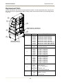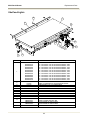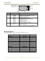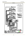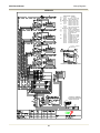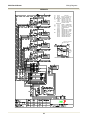
1
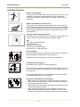
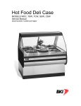
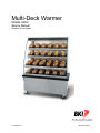
Multi-Deck Warmer
MODEL MDW
Service Manual
Revision C and Higher
CS-TM-002.02
Revised 07/03/12
BKI LIMITED WARRANTY
2812 Grandview Dr. • Simpsonville, SC 29680 • USA
(864) 963-3471 • Toll Free: (800) 927-6887 • Fax: (864) 963-5316
WHAT IS COVERED
This warranty covers defects in material and workmanship under normal use, and applies only
to the original purchaser providing that:
អ The equipment has not been accidentally or intentionally damaged, altered or misused;
អ The equipment is properly installed, adjusted, operated and maintained in accordance with
national and local codes, and in accordance with the installation and operating instructions
provided with this product.
អ The serial number rating plate affixed to the equipment has not been defaced or removed.
WHO IS COVERED
This warranty is extended to the original purchaser and applies only to equipment
purchased for use in the U.S.A.
COVERAGE PERIOD
អ Warranty claims must be received in writing by BKI within one (1) year from date
of installation or within one (1) year and three (3) months from data of shipment from
the factory, whichever comes first.
អ COB Models: One (1) Year limited parts and labor.
អ COM Models: Two (2) Year limited parts and labor. COM convection ovens also have a
two (2) year door warranty.
អ CO1 Models: Two (2) Year limited parts and labor. Five (5) Year limited door
warranty.
អ BevLes Products: Two (2) Year limited parts and labor.
អ Warranty period begins the date of dealer invoice to customer or ninety (90) days
after shipment date from BKI, whichever comes first.
WARRANTY COVERAGE This warranty covers on-site labor, parts and reasonable travel time and travel expenses
of the authorized service representative up to (100) miles round trip and (2) hours travel
time and performed during regular, weekday business hours.
EXCEPTIONS
Any exceptions must be pre-approved in advance and in writing by BKI. The extended door
warranty on convection ovens years 3 through 5 is a parts only warranty and does not include
labor, travel, mileage or any other charges.
EXCLUSIONS
អ Negligence or acts of God,
អ Thermostat calibrations after (30) days from equipment installation date,
អ Air and gas adjustments,
អ Light bulbs,
អ Glass doors and door adjustments,
អ Fuses,
អ Adjustments to burner flames and cleaning of pilot burners,
អ Tightening of screws or fasteners,
អ Failures caused by erratic voltages or gas suppliers,
អ Unauthorized repair by anyone other than a BKI Factory Authorized Service Center,
អ Damage in shipment,
អ Alteration, misuse or improper installation,
អ Thermostats and safety valves with broken capillary tubes,
អ Freight – other than normal UPS charges,
អ Ordinary wear and tear,
អ Failure to follow installation and/or operating instructions,
អ Events beyond control of the company.
INSTALLATION
Leveling, as well as proper installation and check out of all new equipment - per
appropriate installation and use materials – is the responsibility of the dealer or installer,
not the manufacturer.
REPLACEMENT PARTS
BKI genuine Factory OEM parts receive a (90) day materials warranty effective from the
date of installation by a BKI Factory Authorized Service Center.
Warranty is in lieu of all other warranties, expressed or implied, and all other obligations or liabilities on the
manufacturer’s part. BKI shall in no event be liable for any special, indirect or consequential damages, or in any
event for damages in excess of the purchase price of the unit. The repair or replacement of proven defective
parts shall constitute a fulfillment of all obligations under the terms of this warranty.
CS-TM-002.02
Revised 07/03/12
Multi-Deck Warmer
Table of Contents
Table of Contents
Table of Contents ........................................................................................................................................ 1
Introduction.................................................................................................................................................. 2
Safety Precautions .................................................................................................................................... 2
Safety Signs and Messages ................................................................................................................. 2
Safe Work Practices ............................................................................................................................. 3
Operation...................................................................................................................................................... 4
Controls and Indicators ............................................................................................................................. 4
Hardware Controls ................................................................................................................................ 4
Shelf Temperature ................................................................................................................................ 5
Power Up and Preheating ......................................................................................................................... 5
Temperature Adjustment .......................................................................................................................... 5
Operational Guidelines ............................................................................................................................. 5
Unit Shutdown ........................................................................................................................................... 5
Installation.................................................................................................................................................... 6
Unpacking and Handling ........................................................................................................................... 6
Floor Model ............................................................................................................................................... 6
Counter Model........................................................................................................................................... 8
Caster Model ............................................................................................................................................. 8
Wiring ........................................................................................................................................................ 8
Dimensions & Weights .............................................................................................................................. 8
Maintenance ................................................................................................................................................. 9
Scheduled Maintenance ......................................................................................................................... 10
Cleaning .............................................................................................................................................. 10
Troubleshooting ...................................................................................................................................... 11
Replacement Parts .................................................................................................................................... 12
Shelf and Lights ...................................................................................................................................... 13
Switch Plate ............................................................................................................................................ 14
Ballasts .................................................................................................................................................... 14
Wiring Diagrams ........................................................................................................................................ 15
1
Multi-Deck Warmer
Introduction
Introduction
The MDW is a multi-tier, self-serve hot food merchandiser. It consists of heated shelves, individual shelf
lighting, and electronics for powering the shelves, lighting the shelves and controlling the temperature of
each shelf. This unit is for use with prepackaged foods only.
This unit is manufactured by BKI which assures you of the finest in design and engineering -- that it has been
built with care and dedication -- using the best materials available. Attention to the operating instructions
regarding proper installation, operation, and maintenance will result in long lasting dependability to insure the
highest profitable return on your investment.
PLEASE READ THIS ENTIRE MANUAL BEFORE OPERATING THE UNIT. If
you have any questions, please contact your BKI Distributor. If they are unable to
answer your questions, contact the BKI Technical Service Department, toll free:
1-800-927-6887. Outside the U.S., call 1-864-963-3471.
Floor and counter units must be sealed to the mounting surface after installation
to conform to NSF requirements. (Dow Corning RTV #732 Multi-purpose
Sealant.)
Safety Precautions
Always follow recommended safety precautions listed in this manual. Below is the safety alert symbol. When
you see this symbol on your equipment, be alert to the potential for personal injury or property damage.
Safety Signs and Messages
The following Safety signs and messages are placed in this manual to provide instructions and identify
specific areas where potential hazards exist and special precautions should be taken. Know and understand
the meaning of these instructions, signs, and messages. Damage to the equipment, death or serious injury to
you or other persons may result if these messages are not followed.
This message indicates an imminently hazardous situation which, if not avoided,
will result in death or serious injury.
This message indicates a potentially hazardous situation, which, if not avoided,
could result in death or serious injury.
This message indicates a potentially hazardous situation, which, if not avoided,
may result in minor or moderate injury. It may also be used to alert against unsafe
practices.
This message is used when special information, instructions or identification are
required relating to procedures, equipment, tools, capacities and other special
data.
2
Multi-Deck Warmer
Introduction
Safe Work Practices
Beware of High Voltage
This equipment uses high voltage. Serious injury can occur if you or any
untrained or unauthorized person installs, services, or repairs this
equipment. Always Use an Authorized Service agent to Service Your
Equipment
Beware of Hot Surfaces. Do Not Touch.
The shelves in this unit reach temperatures that can cause burns. Use
caution when placing product on and removing product from the shelves.
Do not touch any of the shelves when they are energized. A CAUTION
HOT message is embossed on the front of each shelf to alert you of a
potential hazard.
Keep this manual with the Equipment
This manual is an important part of your equipment. Always keep it near
for easy access. If you need to replace this manual, contact:
BKI
Technical Services Department
2812 Grandview Dr.
Simpsonville, S.C. 29680
Or call toll free: 1-800-927-6887
Outside the U.S., call 864-963-3471
Protect Children
Keep children away from this equipment. Children may not understand
that this equipment is dangerous for them and others.
NEVER allow children to play near or operate your equipment.
Be Prepared for Emergencies
Be prepared for fires, injuries, or other emergencies.
911
Keep a first aid kit and a fire extinguisher near the equipment. You must
use a 40-pound Type BC fire extinguisher and keep it within 25 feet of
your equipment.
Keep emergency numbers for doctors, ambulance services, hospitals,
and the fire department near your telephone.
Know your responsibilities as an Employer
• Make certain your employees know how to operate the equipment.
• Make certain your employees are aware of the safety precautions on
the equipment and in this manual.
• Make certain that you have thoroughly trained your employees about
operating the equipment safely.
• Make certain the equipment is in proper working condition. If you
make unauthorized modifications to the equipment, you will reduce
the function and safety of the equipment as well as void the warranty.
3
Multi-Deck Warmer
Operation
Operation
Controls and Indicators
4
SHELF THERMOSTAT
SOLID BACK UNITS ACCESS FROM FRONT
PASS-THRU UNITS ACCESS FROM BACK
POWER
LIGHTS
OFF
OFF
ON
ON
2
1
3
POWER & LIGHT SWITCH PLATE
SOLID BACK UNITS - LOCATED ON FRONT
PASS-THRU UNITS - LOCATED ON BACK
Figure 1
Hardware Controls
Item #
1
Description
Main Power Switch
2
Lights Circuit Breaker
3
Thermostat for Base
Warmer (Bottom
Shelf)
Thermostat for
Individual Shelf
4
Function
Turns power On or Off to the entire unit. When placed in the On position, the
shelf heaters are powered and the lights illuminate. When placed in the Off
position, power is removed from the entire unit.
Provides circuit protection for the Lights. When placed in the On position
(with the Power Switch in the On position) the illuminate. When placed in
the Off position (with the Power Switch in the On position) power is removed
from lights. If an overload occurs in the light circuit, the Circuit Breaker will
trip causing the actuator to move to the Off position.
Controls the surface temperature of the Base Warmer (Bottom Shelf). Set
the Thermostat dial to a larger number setting to increase the temperature or
a lower number setting to decrease the temperature.
Controls the surface temperature of the individual Shelf. Set the Thermostat
dial to a larger number setting to increase the temperature or a lower
number setting to decrease the temperature.
4
Multi-Deck Warmer
Operation
Shelf Temperature
The temperature of the shelves is controlled by a thermostat on each shelf and on the base of the unit (see
Figure 1). Set each shelf thermostat on “9” for the initial start up of the unit.
Power Up and Preheating
1. Ensure that the power supply cord is connected to an appropriate power receptacle.
2. Place the POWER ON/OFF switch in the ON position.
3. Place the LIGHTS ON/OFF circuit breaker in the ON position.
4. Allow the unit to preheat for a minimum of 30 minutes before loading it with product.
Check Federal and State Health and Sanitation Regulations for internal temperature required for holding
cooked foods for sale. Maintaining these temperatures often tends to allow continued cooking of certain
products. Therefore, smaller amounts of bulk foods should be displayed at non-peak periods and the unit
refilled as needed.
This equipment is not designed to heat-up or cook food. All meat and vegetable products should be
preheated to a minimum of 160°F (70°C) before being placed in the unit.
Temperature Adjustment
After placing the product onto the shelves, it may be necessary to adjust the individual thermostats in order
to maintain the proper internal temperature for the product on display. A thermometer should be used to read
the internal temperature of each product. The thermostats should be adjusted to the lowest possible setting
that will maintain the proper product temperature.
Operational Guidelines
Only use product packaging suitable for the application.
Keep portable meat thermometers on hand. Check the food temperatures hourly. Rotate the food products.
Foods loaded in first should be served first as much as is practical.
Foods held for long periods of time are more difficult to maintain at proper temperature. Also, freshness and
product quality diminish if foods are held too long. Most areas of the country have sanitation regulations
governing how long foods can be held. Make certain to check with your local authorities.
Unit Shutdown
1. Remove product from the unit.
2. Place the POWER ON/OFF circuit breaker in the OFF position.
3. Place the LIGHTS ON/OFF circuit breaker in the OFF position.
4. After the unit has cooled down, remove any residue from the shelves and clean the unit thoroughly.
5
Multi-Deck Warmer
Installation
Installation
Unpacking and Handling
YOU are responsible for filling all freight claims with the delivering truck line. Inspect all cartons and crates
for damage as soon as they arrive. If damage to cartons or crates is found, or if a shortage is found, note this
on the bill of lading (all copies) prior to signing.
If damage is found when the equipment is opened, immediately call the delivering truck line and follow up the
call with a written report indicating concealed damage to your shipment. Ask for an immediate inspection of
your concealed damage item. Packaging material MUST be retained to show the inspector from the truck
line.
Do not place heavy objects on top of the unit or damage could occur. The units
are not structurally designed to support excessive external loading.
Move the unit as close as possible to its permanent location before moving it off of the shipping pallet. Make
certain there are no separately packed accessories before discarding packaging.
Floor Model
Follow the procedure below to level the unit and mount the kick plates. See Error! Reference source not
found..
1. Slide kick plates, ends first, between the base frame and outer panels. Secure in raised position with
tape. Make sure that the end kick plates fit behind the front and rear kick plates.
2. Using a carpenter’s level on the lowest shelf, level the unit by adjusting the leg levelers at the
corners of the unit.
3. Raise the low end of the unit to level it, do not lower the high end.
4. Check for level side-to-side and front-to-back.
5. Remove the tape holding the kick plates in raised position.
6. Make certain that the kick plates are flush to the floor.
7. Drill 9/64” diameter holes in the base frame to match the pre-drilled holes in the kick plates.
8. Attach the kick plates to the base frame with the #8x1/2” black sheet metal screws provided
(SCR355).
9. Seal kick plates to floor using a silicone-type sealant (Dow Corning RTV #732 or equivalent).
6
Multi-Deck Warmer
Installation
Figure 2
7
Multi-Deck Warmer
Installation
Counter Model
Counter mounted units must be mounted on a level surface that can support the weight of the unit and its
contents. Use a carpenter’s level to level the unit.
These units are to be sealed to the counter if required by local health codes. Seal the perimeter of the units
to the counter using a silicone-type sealant (Dow Corning RTV #732 or equivalent).
Caster Model
Caster mounted units must be moved to a permanent location and the two swivel casters locked before
using.
Wiring
A wiring diagram for your specific model is included in this manual. The wiring diagram provides electrical
specifications, an electrical schematic and a parts list. Refer to this wiring diagram and the unit rating plate
for electrical information.
All electrical connections should be in compliance with the NEC and all applicable local codes by a licensed
electrician. Refer to the wiring diagram furnished with your unit for the electrical specifications.
Dimensions & Weights
Electrical Specifications – refer Wiring Diagram listed for each model.
WIDTH + 1/2 in [13 mm]
10 1/2 in
41 1/8 in [266 mm]
[1045 mm]
Counter
Model
10 5/16 in
[263 mm]
10 5/8 in
[269 mm]
56 3/16 in
[1426 mm]
Floor
Model
20 5/8 in
[525 mm]
10 5/8 in
[269 mm]
20 5/8 in
[523 mm]
8 1/16 in
[205 mm]
23 1/8 in
[587 mm]
25 15/16 in
[659 mm]
CASCADE
16 in
[407 mm]
VERTICAL
25 15/16 in
[659 mm]
WIDE VERTICAL
WIDTH + 2 9/16 in [65 mm]
WIDTH + 4 13/16 in [122 mm]
Figure 3
3 Shelf Merchandisers
Model
MDW36-3C
MDW36-3V
MDW36-3WV
MDW48-3C
MDW48-3V
MDW48-3WV
Diagram
CASCADE
VERTICAL
WIDE VERTICAL
CASCADE
VERTICAL
WIDE VERTICAL
Width
36 in [914 mm]
36 in [914 mm]
36 in [914 mm]
48 in [1219 mm]
48 in [1219 mm]
48 in [1219 mm]
8
Wiring Diagram
EB68694600
EB68694700
EB68694800
EB68693600
EB68693700
EB68693800
Shipping Wt.
Counter
Floor
300 lb [136 kg] 360 lb [163 kg]
200 lb [91 kg]
240 lb [163 kg]
330 lb [150 kg] 390 lb [177 kg]
380 lb [172 kg] 440 lb [200 kg]
280 lb [127 kg] 320 lb [145 kg]
420 lb [190 kg] 480 lb [218 kg]
Multi-Deck Warmer
WIDTH + 1/2 in [13 mm]
9 in
[229 mm]
10 5/8 in
[269 mm]
50 1/8 in
[1273 mm]
10 1/2 in
Counter
[266 mm]
Model
10 5/16 in
[263 mm]
65 3/16 in
[1655 mm]
Floor
Model
20 5/8 in
[523 mm]
10 5/8 in
[269 mm]
20 5/8 in
[523 mm]
8 1/16 in
[205 mm]
23 1/8 in
[587 mm]
25 15/16 in
[659 mm]
16 in
[407 mm]
25 15/16 in
[659 mm]
CASCADE
VERTICAL
WIDE VERTICAL
WIDTH + 2 9/16 in [65 mm]
WIDTH + 4 13/16 in [122 mm]
Figure 4
4 Shelf Merchandisers
Model
MDW36-4C
MDW36-4V
MDW36-4WV
MDW48-4C
MDW48-4V
MDW48-4WV
Diagram
CASCADE
VERTICAL
WIDE VERTICAL
CASCADE
VERTICAL
WIDE VERTICAL
Width
36 in [914 mm]
36 in [914 mm]
36 in [914 mm]
48 in [1219 mm]
48 in [1219 mm]
48 in [1219 mm]
Wiring Diagram
EB68694300
EB68694400
EB68694500
EB68693300
EB68693400
EB68693500
Shipping Wt.
Counter
Floor
480 lb [218 kg] 540 lb [245 kg]
380 lb [172 kg] 420 lb [191 kg]
510 lb [231 kg] 570 lb [258 kg]
560 lb [245 kg] 620 lb [281 kg]
460 lb [208 kg] 500 lb [227 kg]
600 lb [272 kg] 660 lb [299 kg]
WIDTH + 1/2 in [13 mm]
9 in
[229 mm]
9 in
59 1/8 in [229 mm]
[1502 mm]
Counter
Model
10 1/2 in
[266 mm]
10 5/16 in
[263 mm]
74 3/16 in
[1884 mm]
Floor
Model
20 5/8 in
[523 mm]
10 5/8 in
[269 mm]
20 5/8 in
[523 mm]
8 1/16 in
[205 mm]
23 1/8 in
[587 mm]
16 in
[407 mm]
25 15/16 in
[659 mm]
CASCADE
25 15/16 in
[659 mm]
WIDTH + 2 9/16 in [65 mm]
WIDTH + 4 13/16 in [122 mm]
Figure 5
5 Shelf Merchandisers
Model
MDW36-5C
MDW36-5V
MDW36-5WV
MDW48-5C
MDW48-5V
MDW48-5WV
Diagram
CASCADE
VERTICAL
WIDE VERTICAL
CASCADE
VERTICAL
WIDE VERTICAL
Width
36 in [914 mm]
36 in [914 mm]
36 in [914 mm]
48 in [1219 mm]
48 in [1219 mm]
48 in [1219 mm]
9
Wiring Diagram
EB68694000
EB68694100
EB68694200
EB68693000
EB68693100
EB68693200
Shipping Wt.
Counter
Floor
480 lb [218 kg] 540 lb [245 kg]
380 lb [172 kg] 420 lb [191 kg]
510 lb [231 kg] 570 lb [258 kg]
560 lb [245 kg] 620 lb [281 kg]
460 lb [208 kg] 500 lb [227 kg]
600 lb [272 kg] 660 lb [299 kg]
Multi-Deck Warmer
Maintenance
Maintenance
Failure to comply with the maintenance below could result in a serious accident.
Electrocution, equipment failure or property damage could result if an unlicensed
electrician performs electrical repair. Ensure that a licensed electrician performs
electrical repair.
Scheduled Maintenance
Use the following table to help manage scheduled maintenance activities.
Frequency
Performed By
Part
Activity
Daily
User
Unit
Clean the entire Unit. Refer to the cleaning
procedure below.
Monthly
User
Shelf Power
ON/OFF Circuit
Breaker
Press push-to-test button to test overload,
short circuit and ground fault protection
capability.
Cleaning
This unit should be cleaned at the end of each day. Use the following procedure:
Failure to remove power from this unit may cause severe electrical shock. This
unit may have more than one disconnect switch.
1. Place the POWER ON/OFF circuit breaker in the OFF position.
2. Place the LIGHTS ON/OFF circuit breaker in the OFF position.
3. Allow unit to cool down.
4. Disconnect power from the unit by unplugging it from the power receptacle.
5. Remove product from the shelves.
Always wear appropriate personal protection equipment during the cleaning process
to guard against possible injury.
Using abrasive cleaners may damage the cabinet finish. Use mild soap and water
only.
DO NOT USE OVEN CLEANER on this machine. Caustic cleaners will damage the
equipment.
Never get excess water on the unit as this can cause damage to the unit.
This equipment is not intended to be cleaned with a water jet.
6. Use a mild soap and water solution to clean the unit.
7. Sponge the inside and outside with a mild soap and water solution.
8. Wipe the unit dry with a soft, clean cloth.
10
Multi-Deck Warmer
Maintenance
Troubleshooting
Refer to the table below for troubleshooting information.
Problem
Shelves Not Heating and
Lights Not On
Cause
Possible Solution
Unit not plugged into power
receptacle.
Ensure unit power cord is
connected to appropriate power
receptacle.
Check circuit breaker or fuses at
building power panel. If problem
persists, contact an authorized
BKI service agent for corrective
action.
Place the Power circuit breaker
ON and the Lights circuit breaker
ON.
Contact an authorized BKI service
agent for corrective action.
Replace lamp only with BKI
shatter-proof lamp.
Contact an authorized BKI service
agent for corrective action.
Refer to the preheating section on
page 5. If problem persists,
contact an authorized BKI service
agent for corrective action.
Check product temperature
before loading the unit.
No Power to the unit.
Power switch is OFF and Lights
circuit breaker is OFF.
No Heat to Single Shelf
Failed shelf component.
Individual Light is not On
Failed Fluorescent Lamp.
Fail Lamp Ballast
Holding Temperature Not
Adequate
Unit has not been preheated.
Product is below 160° F when
loaded.
Shelf temperature control not
set properly.
Failed shelf component.
11
Adjust the shelf temperature
control. Refer to the section
entitled Temperature Adjustment
on page 5.
Contact an authorized BKI service
agent for corrective action.
Multi-Deck Warmer
Replacement Parts
Replacement Parts
Use the information in this section to identify replacement parts. To order replacement parts, call your local
BKI sales and service representative. Before calling, please note the serial number on the rating tag affixed
to the unit.
2
1
4
SWITCH PLATE – LOCATED IN
FRONT ON SOLID BACK UNITS
3
5
ITEM #
1.
6
REMOVE COVER TO
ACCESS BALLAST(S)
2.
3.
4.
5.
6.
PART #
DESCRIPTION
GL0325
GL0326
GL0327
GL0328
GL0329
GL0330
GL0331
GL0332
GL0333
END GLASS, 3 SHELF VERTICAL
END GLASS, 4 SHELF VERTICAL
END GLASS, 5 SHELF VERTICAL
END GLASS, 3 SHELF CASCADE
END GLASS, 4 SHELF CASCADE
END GLASS, 5 SHELF CASCADE
END GLASS, 3 SHELF WIDE VERTICAL
END GLASS, 4 SHELF WIDE VERTICAL
END GLASS, 5 SHELF WIDE VERTICAL
BLT261
B0233
BOLT, 1/4”-20 x 23 mm JOINT
CYLINDER BEARING
D0380*
D0382*
D0384*
D0386*
D0388*
D0390*
LEFT INSIDE DOOR –
36” WIDE x 5 SHELVES
36” WIDE x 4 SHELVES
36” WIDE x 3 SHELVES
48” WIDE x 5 SHELVES
48” WIDE x 4 SHELVES
48” WIDE x 3 SHELVES
D0381*
D0383*
D0385*
D0387*
D0389*
D0391*
RIGHT OUTSIDE DOOR –
36” WIDE x 5 SHELVES
36” WIDE x 4 SHELVES
36” WIDE x 3 SHELVES
48” WIDE x 5 SHELVES
48” WIDE x 4 SHELVES
48” WIDE x 3 SHELVES
EB68692700
F0157
NUT271
or
EB68692800
F0160
CORDSET, 208V – 230V
CORD GRIP, 90°
NUT, 1/2” ELECTRICAL
or
CORDSET, 120V
STRAIN RELIEF BUSHING
C0415
C0426
or
L0151
CASTER, 3” SWIVEL
CASTER, 3” RIGID
or
LEG LEVELER
* ADD “S” SUFFIX TO PART NUMBER FOR REFLECTIVE DOORS
12
Multi-Deck Warmer
Replacement Parts
Shelf and Lights
13
1
11
12
10
8
7
3
ITEM #
1.
2.
3.
4.
5.
6.
7.
8.
9.
10.
11.
12.
13.
5
9
6
4
2
PART #
AN6865800S
AN6865810S
AN6865820S
AN6865830S
AN6865840S
AN6865850S
AN6865860S
AN6865870S
AN6865880S
AN6865890S
AN6865900S
AN6865910S
FL0041
FL0042
FL0100
T0109
T0175
T0174
K0040
N0621
SP0048
NUT253
FB68632203
FB68632403
FB68632303
FB68632503
SCR121
DESCRIPTION
10" X 36" SHELF TOP w/ HEATING ELEMENT, 120V
10" X 36" SHELF TOP w/ HEATING ELEMENT, 208V
10" X 36" SHELF TOP w/ HEATING ELEMENT, 230V
20" X 36" SHELF TOP w/ HEATING ELEMENT, 120V
20" X 36" SHELF TOP w/ HEATING ELEMENT, 208V
20" X 36" SHELF TOP w/ HEATING ELEMENT, 230V
10" X 48" SHELF TOP w/ HEATING ELEMENT, 120V
10" X 48" SHELF TOP w/ HEATING ELEMENT, 208V
10" X 48" SHELF TOP w/ HEATING ELEMENT, 230V
20" X 48" SHELF TOP w/ HEATING ELEMENT, 120V
20" X 48" SHELF TOP w/ HEATING ELEMENT, 208V
20" X 48" SHELF TOP w/ HEATING ELEMENT, 230V
LAMP, FLUORESCENT F25T8 SHATTER-PROOF
LAMP, FLUORESCENT F32T8 SHATTER-PROOF
LAMPHOLDER CAP, (FLUORESCENT)
THERMOSTAT, 150F – 250F
POTENTIOMETER with LEADS
PROBE, THERMISTOR with LEADS
KNOB 1 1/2” INSTRUMENT
DECAL, SHELF THERMOSTAT
SPACER, #6 x 3/16” NYLON
NUT, #6-32 LOCK
FRONT GUARD 36" SHELF MDW
FRONT GUARD 48"SHELF MD
BACK GUARD 36" SHELF MDW
BACK GUARD 48" SHELF MDW
SCREW, #10-24 x 3/4” THUMB
13
Multi-Deck Warmer
Replacement Parts
Switch Plate
10
2
1
11
3
9
8
6
ITEM #
1.
2.
3.
4.
5.
6.
7.
8.
9.
10.
11.
7
4
5
PART #
T0109
T0175
T0174
CB0065
S0356
DESCRIPTION
THERMOSTAT, 150F – 250F
POTENTIOMETER with LEADS
PROBE, THERMISTOR with LEADS
CIRCUIT BREAKER, 2.5A, 2P
SWITCH, ILLUMINATED ROCKER
N0507
N0508
K0040
N0621
SP0047
NUT253
DECAL, POWER
DECAL, LIGHTS
KNOB 1 ½” INSTRUMENT
DECAL, SHELF THERMOSTAT
SPACER, #6 x 5/16” NYLON
NUT, #6-32 LOCK
Ballasts
14
Multi-Deck Warmer
Wiring Diagrams
REMOVE COVER ON
BACK OF UNIT TO
ACCESS BALLAST(S)
3
2
4
1
ITEM #
1.
PART #
B0095
DESCRIPTION
BALLAST, 3 LAMP T8, 120/277V
2.
TB0065
TB0067
TB0068
TERM BLOCK 4 CONDUCTOR W/MTG FOOT
TERM BLOCK 2 CONDUCTOR
TERM BLOCK END PLATE
3.
TB0100
TB0101
TB0102
TB0109
TB0106
TERMINAL SECTION, 3 POLE
TERMINAL SECTION, 3 POLE GROUND
TERMINAL END PLATE
TERMINAL END STOP
TERMINAL JUMPER, 2 POSITION
SCR091
SP0031
Screw, #10-24 x ¾” Nylon Pan Head
Spacer, ∅3/8” x 3/16”
Do Not use metallic hardware to mount Ballasts
4.
Wiring Diagrams
Refer to the table below to find the wiring diagram associated with your unit.
Model
MDW36-3C
MDW36-3V
MDW36-3VW
MDW36-4C
MDW36-4V
MDW36-4VW
MDW36-5C
MDW36-5V
MDW36-5VW
MDW48-3C
MDW48-3V
MDW48-3VW
MDW48-4C
MDW48-4V
MDW48-4VW
MDW48-5C
MDW48-5V
MDW48-5VW
Drawing #
SB68696600
SB68696700
SB68696800
SB68696300
SB68696400
SB68696500
SB68696000
SB68696100
SB68696200
SB68695600
SB68695700
SB68695800
SB68695300
SB68695400
SB68695500
SB68695000
SB68695100
SB68695200
15
Page #
16
17
18
19
20
21
22
23
24
25
26
27
28
29
30
31
32
33
Multi-Deck Warmer
Wiring Diagrams
MDW36-3C
COMPONENT LEGEND
Key
Part No.
B1
B0084
CB1
CB0065
EB68692700
CS1
EB68692800
H1
C0362
C0363
C0364
H2
C0359
C0360
C0361
L1
FL0041
MA68653400
P1
T0174
SW1
S0356
T1
T0109
T0175
K0040
TB1
TB0067
TB0065
TB0068
TB2
TB0100
TB0101
TB0106
TB0102
TB0109
Description
BALLAST, T8, 120V-240V
CIRCUIT BREAKER, 2P
CORDSET, 250V (USA)
CORDSET, 120V (USA)
HEATER, 20"x36", 120V
HEATER, 20"x36", 208V
HEATER, 20"x36", 230V
HEATER, 10"x36", 120V
HEATER, 10"x36", 208V
HEATER, 10"x36", 230V
LAMP, SHATTER-PROOF
SHROUD, T8 LAMP
PROBE, 3" THERMISTOR
SWITCH, ROCKER, DPST
THERMOSTAT, 150F-250F
POTENTIOMETER
KNOB
TERMINAL SEC, 2 COND
TERMINAL SEC, 4 COND
TERMINAL END PLATE
TERMINAL SEC, 3P
TERMINAL SEC, 3P GND
JUMPER, 2 POSITION
TERMINAL END PLATE
TERMINAL END STOP
COM 24/100 24/120 240
Relay
TO
HEATER
120V UNITS - CONNECT
WIRE #1 HERE
Relay
POT
Aux 1
Ext Pot
Aux 3
Probe
Aux 2
THERMOSTAT CONNECTION DIAGRAM
COM 24/100 24/120 240
Aux 3
16
Relay
Aux 1
Aux 2
Probe
Relay
Multi-Deck Warmer
Wiring Diagrams
MDW36-3V
Key
Part No.
B1
B0084
CB1
CB0065
CS1 EB68692700
EB68692800
H1
C0359
C0360
C0361
L1
FL0041
MA68653400
P1
T0174
SW1
S0356
T1
T0109
T0175
K0040
TB1
TB0067
TB0065
TB0068
TB2
TB0100
TB0101
TB0106
TB0102
TB0109
Description
BALLAST, T8, 120V-240V
CIRCUIT BREAKER, 2P
CORDSET, 250V (USA)
CORDSET, 120V (USA)
HEATER, 10"x36", 120V
HEATER, 10"x36", 208V
HEATER, 10"x36", 230V
LAMP, SHATTER-PROOF
SHROUD, T8 LAMP
PROBE, 3" THERMISTOR
SWITCH, ROCKER, DPST
THERMOSTAT, 150F-250F
POTENTIOMETER
KNOB
TERMINAL SEC, 2 COND
TERMINAL SEC, 4 COND
TERMINAL END PLATE
TERMINAL SEC, 3P
TERMINAL SEC, 3P GND
JUMPER, 2 POSITION
TERMINAL END PLATE
TERMINAL END STOP
COM 24/100 24/120 240
Relay
TO
HEATER
120V UNITS - CONNECT
WIRE #1 HERE
Relay
POT
Aux 1
Ext Pot
Aux 3
Probe
Aux 2
THERMOSTAT CONNECTION DIAGRAM
COM 24/100 24/120 240
Aux 3
17
Relay
Aux 1
Aux 2
Probe
Relay
Multi-Deck Warmer
Wiring Diagrams
MDW36-3WV
COMPONENT LEGEND
Key
Part No.
B1
B0084
CB1
CB0065
CS1 EB68692700
EB68692800
H1
C0362
C0363
C0364
L1
FL0041
MA68653400
P1
T0174
SW1
S0356
T1
T0109
T0175
K0040
TB1
TB0067
TB0065
TB0068
TB2
TB0100
TB0101
TB0106
TB0102
TB0109
Description
BALLAST, T8, 120V-240V
CIRCUIT BREAKER, 2P
CORDSET, 250V (USA)
CORDSET, 120V (USA)
HEATER, 20"x36", 120V
HEATER, 20"x36", 208V
HEATER, 20"x36", 230V
LAMP, SHATTER-PROOF
SHROUD, T8 LAMP
PROBE, 3" THERMISTOR
SWITCH, ROCKER, DPST
THERMOSTAT, 150F-250F
POTENTIOMETER
KNOB
TERMINAL SEC, 2 COND
TERMINAL SEC, 4 COND
TERMINAL END PLATE
TERMINAL SEC, 3P
TERMINAL SEC, 3P GND
JUMPER, 2 POSITION
TERMINAL END PLATE
TERMINAL END STOP
COM 24/100 24/120 240
Relay
TO
HEATER
120V UNITS - CONNECT
WIRE #1 HERE
Relay
POT
Aux 1
Ext Pot
Aux 3
Probe
Aux 2
THERMOSTAT CONNECTION DIAGRAM
COM 24/100 24/120 240
Aux 3
18
Relay
Aux 1
Aux 2
Probe
Relay
Multi-Deck Warmer
Wiring Diagrams
MDW36-4C
COMPONENT LEGEND
Key
Part No.
B0084
B1
CB1
CB0065
CS1 EB68692700
EB68692800
C0362
H1
C0363
C0364
H2
C0359
C0360
C0361
L1
FL0041
MA68653400
P1
T0174
SW1
S0356
T1
T0109
T0175
K0040
TB1
TB0067
TB0065
TB0068
TB2
TB0100
TB0101
TB0106
TB0102
TB0109
Description
BALLAST, T8, 120V-240V
CIRCUIT BREAKER, 2P
CORDSET, 250V (USA)
CORDSET, 120V (USA)
HEATER, 20"x36", 120V
HEATER, 20"x36", 208V
HEATER, 20"x36", 230V
HEATER, 10"x36", 120V
HEATER, 10"x36", 208V
HEATER, 10"x36", 230V
LAMP, SHATTER-PROOF
SHROUD, T8 LAMP
PROBE, 3" THERMISTOR
SWITCH, ROCKER, DPST
THERMOSTAT, 150F-250F
POTENTIOMETER
KNOB
TERMINAL SEC, 2 COND
TERMINAL SEC, 4 COND
TERMINAL END PLATE
TERMINAL SEC, 3P
TERMINAL SEC, 3P GND
JUMPER, 2 POSITION
TERMINAL END PLATE
TERMINAL END STOP
COM 24/100 24/120 240
Relay
TO
HEATER
120V UNITS - CONNECT
WIRE #1 HERE
Relay
POT
Aux 1
Ext Pot
Aux 3
Probe
Aux 2
THERMOSTAT CONNECTION DIAGRAM
COM 24/100 24/120 240
Aux 3
19
Relay
Aux 1
Aux 2
Probe
Relay
Multi-Deck Warmer
Wiring Diagrams
MDW36-4V
COMPONENT LEGEND
Key
Part No.
B0084
B1
CB1
CB0065
EB68692700
CS1
EB68692800
H1
C0359
C0360
C0361
L1
FL0041
MA68653400
P1
T0174
SW1
S0356
T1
T0109
T0175
K0040
TB1
TB0067
TB0065
TB0068
TB2
TB0100
TB0101
TB0106
TB0102
TB0109
Description
BALLAST, T8, 120V-240V
CIRCUIT BREAKER, 2P
CORDSET, 250V (USA)
CORDSET, 120V (USA)
HEATER, 10"x36", 120V
HEATER, 10"x36", 208V
HEATER, 10"x36", 230V
LAMP, SHATTER-PROOF
SHROUD, T8 LAMP
PROBE, 3" THERMISTOR
SWITCH, ROCKER, DPST
THERMOSTAT, 150F-250F
POTENTIOMETER
KNOB
TERMINAL SEC, 2 COND
TERMINAL SEC, 4 COND
TERMINAL END PLATE
TERMINAL SEC, 3P
TERMINAL SEC, 3P GND
JUMPER, 2 POSITION
TERMINAL END PLATE
TERMINAL END STOP
COM 24/100 24/120 240
Relay
TO
HEATER
120V UNITS - CONNECT
WIRE #1 HERE
Relay
POT
Aux 1
Ext Pot
Aux 3
Probe
Aux 2
THERMOSTAT CONNECTION DIAGRAM
COM 24/100 24/120 240
Aux 3
20
Relay
Aux 1
Aux 2
Probe
Relay
Multi-Deck Warmer
Wiring Diagrams
MDW36-4WV
COMPONENT LEGEND
Description
Key
Part No.
BALLAST, T8, 120V-240V
B1
B0084
CIRCUIT
BREAKER, 2P
CB1
CB0065
CS1 EB68692700 CORDSET, 250V (USA)
HEATER, 20"x36", 208V
H1
C0363
HEATER, 20"x36", 230V
C0364
LAMP, SHATTER-PROOF
L1
FL0041
MA68653400 SHROUD, T8 LAMP
P1
PROBE, 3" THERMISTOR
T0174
SW1
SWITCH, ROCKER, DPST
S0356
T1
T0109
THERMOSTAT, 150F-250F
T0175
POTENTIOMETER
K0040
KNOB
TB1
TB0067
TERMINAL SEC, 2 COND
TB0065
TERMINAL SEC, 4 COND
TB0068
TERMINAL END PLATE
TB2
TB0100
TERMINAL SEC, 3P
TB0101
TERMINAL SEC, 3P GND
TB0106
JUMPER, 2 POSITION
TB0102
TERMINAL END PLATE
TB0109
TERMINAL END STOP
COM 24/100 24/120 240
Relay
TO
HEATER
120V UNITS - CONNECT
WIRE #1 HERE
Relay
POT
Aux 1
Ext Pot
Aux 3
Probe
Aux 2
THERMOSTAT CONNECTION DIAGRAM
COM 24/100 24/120 240
Aux 3
21
Relay
Aux 1
Aux 2
Probe
Relay
Multi-Deck Warmer
Wiring Diagrams
MDW36-5C
Description
Key
Part No.
BALLAST, T8, 120V-240V
B1
B0084
CIRCUIT
BREAKER, 2P
CB1
CB0065
CS1 EB68692700 CORDSET, 250V (USA)
HEATER, 20"x36", 208V
H1
C0363
HEATER, 20"x36", 230V
C0364
HEATER, 10"x36", 208V
H2
C0360
HEATER, 10"x36", 230V
C0361
LAMP, SHATTER-PROOF
L1
FL0041
MA68653400 SHROUD, T8 LAMP
P1
PROBE, 3" THERMISTOR
T0174
SW1
SWITCH, ROCKER, DPST
S0356
T1
THERMOSTAT, 150F-250F
T0109
POTENTIOMETER
T0175
K0040
KNOB
TB1
TB0067
TERMINAL SEC, 2 COND
TB0065
TERMINAL SEC, 4 COND
TB0068
TERMINAL END PLATE
TB2
TB0100
TERMINAL SEC, 3P
TB0101
TERMINAL SEC, 3P GND
TB0106
JUMPER, 2 POSITION
TB0102
TERMINAL END PLATE
TB0109
TERMINAL END STOP
COM 24/100 24/120 240
Relay
TO
HEATER
120V UNITS - CONNECT
WIRE #1 HERE
Relay
POT
Aux 1
Ext Pot
Aux 3
Probe
Aux 2
THERMOSTAT CONNECTION DIAGRAM
COM 24/100 24/120 240
Aux 3
22
Relay
Aux 1
Aux 2
Probe
Relay
Multi-Deck Warmer
Wiring Diagrams
MDW36-5V
COMPONENT LEGEND
Key
Part No.
B0084
B1
CB1
CB0065
EB68692700
CS1
EB68692800
H1
C0359
C0360
C0361
L1
FL0041
MA68653400
P1
T0174
SW1
S0356
T1
T0109
T0175
K0040
TB1
TB0067
TB0065
TB0068
TB2
TB0100
TB0101
TB0106
TB0102
TB0109
Description
BALLAST, T8, 120V-240V
CIRCUIT BREAKER, 2P
CORDSET, 250V (USA)
CORDSET, 120V (USA)
HEATER, 10"x36", 120V
HEATER, 10"x36", 208V
HEATER, 10"x36", 230V
LAMP, SHATTER-PROOF
SHROUD, T8 LAMP
PROBE, 3" THERMISTOR
SWITCH, ROCKER, DPST
THERMOSTAT, 150F-250F
POTENTIOMETER
KNOB
TERMINAL SEC, 2 COND
TERMINAL SEC, 4 COND
TERMINAL END PLATE
TERMINAL SEC, 3P
TERMINAL SEC, 3P GND
JUMPER, 2 POSITION
TERMINAL END PLATE
TERMINAL END STOP
COM 24/100 24/120 240
Relay
TO
HEATER
120V UNITS - CONNECT
WIRE #1 HERE
Relay
POT
Aux 1
Ext Pot
Aux 3
Probe
Aux 2
THERMOSTAT CONNECTION DIAGRAM
COM 24/100 24/120 240
Aux 3
23
Relay
Aux 1
Aux 2
Probe
Relay
Multi-Deck Warmer
Wiring Diagrams
MDW36-5WV
COMPONENT LEGEND
Description
Key
Part No.
BALLAST, T8, 120V-240V
B1
B0084
CIRCUIT BREAKER, 2P
CB1
CB0065
CS1 EB68692700 CORDSET, 250V (USA)
HEATER, 20"x36", 208V
H1
C0363
HEATER, 20"x36", 230V
C0364
LAMP, SHATTER-PROOF
L1
FL0041
MA68653400 SHROUD, T8 LAMP
P1
PROBE, 3" THERMISTOR
T0174
SWITCH, ROCKER, DPST
SW1
S0356
T1
THERMOSTAT, 150F-250F
T0109
T0175
POTENTIOMETER
K0040
KNOB
TB1
TB0067
TERMINAL SEC, 2 COND
TB0065
TERMINAL SEC, 4 COND
TB0068
TERMINAL END PLATE
TB2
TB0100
TERMINAL SEC, 3P
TB0101
TERMINAL SEC, 3P GND
TB0106
JUMPER, 2 POSITION
TB0102
TERMINAL END PLATE
TB0109
TERMINAL END STOP
COM 24/100 24/120 240
Relay
TO
HEATER
120V UNITS - CONNECT
WIRE #1 HERE
Relay
POT
Aux 1
Ext Pot
Aux 3
Probe
Aux 2
THERMOSTAT CONNECTION DIAGRAM
COM 24/100 24/120 240
Aux 3
24
Relay
Aux 1
Aux 2
Probe
Relay
Multi-Deck Warmer
Wiring Diagrams
MDW48-3C
COMPONENT LEGEND
Key
Part No.
B0084
B1
CB1
CB0065
CS1 EB68692700
EB68692800
C0368
H1
C0369
C0370
H2
C0365
C0366
C0367
L1
FL0042
MA68653400
P1
T0174
SW1
S0356
T1
T0109
T0175
K0040
TB1
TB0067
TB0065
TB0068
TB2
TB0100
TB0101
TB0106
TB0102
TB0109
Description
BALLAST, T8, 120V-240V
CIRCUIT BREAKER, 2P
CORDSET, 250V (USA)
CORDSET, 120V (USA)
HEATER, 20"x48", 120V
HEATER, 20"x48", 208V
HEATER, 20"x48", 230V
HEATER, 10"x48", 120V
HEATER, 10"x48", 208V
HEATER, 10"x48", 230V
LAMP, SHATTER-PROOF
SHROUD, T8 LAMP
PROBE, 3" THERMISTOR
SWITCH, ROCKER, DPST
THERMOSTAT, 150F-250F
POTENTIOMETER
KNOB
TERMINAL SEC, 2 COND
TERMINAL SEC, 4 COND
TERMINAL END PLATE
TERMINAL SEC, 3P
TERMINAL SEC, 3P GND
JUMPER, 2 POSITION
TERMINAL END PLATE
TERMINAL END STOP
COM 24/100 24/120 240
Relay
TO
HEATER
120V UNITS - CONNECT
WIRE #1 HERE
Relay
POT
Aux 1
Ext Pot
Aux 3
Probe
Aux 2
THERMOSTAT CONNECTION DIAGRAM
COM 24/100 24/120 240
Aux 3
25
Relay
Aux 1
Probe
Aux 2
Relay
Multi-Deck Warmer
Wiring Diagrams
MDW48-3V
COMPONENT LEGEND
Key
Part No.
B1
B0084
CB1
CB0065
CS1 EB68692700
EB68692800
H1
C0359
C0360
C0361
L1
FL0042
MA68653400
P1
T0174
SW1
S0356
T1
T0109
T0175
K0040
TB1
TB0067
TB0065
TB0068
TB2
TB0100
TB0101
TB0106
TB0102
TB0109
Description
BALLAST, T8, 120V-240V
CIRCUIT BREAKER, 2P
CORDSET, 250V (USA)
CORDSET, 120V (USA)
HEATER, 10"x36", 120V
HEATER, 10"x36", 208V
HEATER, 10"x36", 230V
LAMP, SHATTER-PROOF
SHROUD, T8 LAMP
PROBE, 3" THERMISTOR
SWITCH, ROCKER, DPST
THERMOSTAT, 150F-250F
POTENTIOMETER
KNOB
TERMINAL SEC, 2 COND
TERMINAL SEC, 4 COND
TERMINAL END PLATE
TERMINAL SEC, 3P
TERMINAL SEC, 3P GND
JUMPER, 2 POSITION
TERMINAL END PLATE
TERMINAL END STOP
COM 24/100 24/120 240
Relay
TO
HEATER
120V UNITS - CONNECT
WIRE #1 HERE
Relay
POT
Aux 1
Ext Pot
Aux 3
Probe
Aux 2
THERMOSTAT CONNECTION DIAGRAM
COM 24/100 24/120 240
Aux 3
26
Relay
Aux 1
Aux 2
Probe
Relay
Multi-Deck Warmer
Wiring Diagrams
MDW48-3WV
COMPONENT LEGEND
Description
Key
Part No.
BALLAST, T8, 120V-240V
B1
B0084
CIRCUIT
BREAKER, 2P
CB1
CB0065
CS1 EB68692700 CORDSET, 250V (USA)
HEATER, 20"x48", 208V
H1
C0369
HEATER, 20"x48", 230V
C0370
LAMP, SHATTER-PROOF
L1
FL0042
MA68653400 SHROUD, T8 LAMP
P1
T0174
PROBE, 3" THERMISTOR
SW1
SWITCH, ROCKER, DPST
S0356
T1
T0109
THERMOSTAT, 150F-250F
T0175
POTENTIOMETER
K0040
KNOB
TB1
TB0067
TERMINAL SEC, 2 COND
TB0065
TERMINAL SEC, 4 COND
TB0068
TERMINAL END PLATE
TB2
TB0100
TERMINAL SEC, 3P
TB0101
TERMINAL SEC, 3P GND
TB0106
JUMPER, 2 POSITION
TB0102
TERMINAL END PLATE
TB0109
TERMINAL END STOP
COM 24/100 24/120 240
Relay
TO
HEATER
120V UNITS - CONNECT
WIRE #1 HERE
Relay
POT
Aux 1
Ext Pot
Aux 3
Probe
Aux 2
THERMOSTAT CONNECTION DIAGRAM
COM 24/100 24/120 240
Aux 3
27
Relay
Aux 1
Aux 2
Probe
Relay
Multi-Deck Warmer
Wiring Diagrams
MDW48-4C
COMPONENT LEGEND
Description
Key
Part No.
BALLAST, T8, 120V-240V
B1
B0084
CIRCUIT
BREAKER, 2P
CB1
CB0065
CS1 EB68692700 CORDSET, 250V (USA)
HEATER, 20"x48", 208V
H1
C0369
HEATER, 20"x48", 230V
C0370
HEATER, 10"x48", 208V
H2
C0366
HEATER, 10"x48", 230V
C0367
LAMP, SHATTER-PROOF
L1
FL0042
MA68653400 SHROUD, T8 LAMP
P1
PROBE, 3" THERMISTOR
T0174
SW1
SWITCH, ROCKER, DPST
S0356
T1
THERMOSTAT, 150F-250F
T0109
POTENTIOMETER
T0175
K0040
KNOB
TB1
TB0067
TERMINAL SEC, 2 COND
TB0065
TERMINAL SEC, 4 COND
TB0068
TERMINAL END PLATE
TB2
TB0100
TERMINAL SEC, 3P
TB0101
TERMINAL SEC, 3P GND
TB0106
JUMPER, 2 POSITION
TB0102
TERMINAL END PLATE
TB0109
TERMINAL END STOP
COM 24/100 24/120 240
Relay
TO
HEATER
120V UNITS - CONNECT
WIRE #1 HERE
Relay
POT
Aux 1
Ext Pot
Aux 3
Probe
Aux 2
THERMOSTAT CONNECTION DIAGRAM
COM 24/100 24/120 240
Aux 3
28
Relay
Aux 1
Aux 2
Probe
Relay
Multi-Deck Warmer
Wiring Diagrams
MDW48-4V
COMPONENT LEGEND
Key
Part No.
B0084
B1
CB1
CB0065
EB68692700
CS1
EB68692800
H1
C0365
C0366
C0367
L1
FL0042
MA68653400
P1
T0174
SW1
S0356
T1
T0109
T0175
K0040
TB1
TB0067
TB0065
TB0068
TB2
TB0100
TB0101
TB0106
TB0102
TB0109
Description
BALLAST, T8, 120V-240V
CIRCUIT BREAKER, 2P
CORDSET, 250V (USA)
CORDSET, 120V (USA)
HEATER, 10"x48", 120V
HEATER, 10"x48", 208V
HEATER, 10"x48", 230V
LAMP, SHATTER-PROOF
SHROUD, T8 LAMP
PROBE, 3" THERMISTOR
SWITCH, ROCKER, DPST
THERMOSTAT, 150F-250F
POTENTIOMETER
KNOB
TERMINAL SEC, 2 COND
TERMINAL SEC, 4 COND
TERMINAL END PLATE
TERMINAL SEC, 3P
TERMINAL SEC, 3P GND
JUMPER, 2 POSITION
TERMINAL END PLATE
TERMINAL END STOP
COM 24/100 24/120 240
Relay
TO
HEATER
120V UNITS - CONNECT
WIRE #1 HERE
Relay
POT
Aux 1
Ext Pot
Aux 3
Probe
Aux 2
THERMOSTAT CONNECTION DIAGRAM
COM 24/100 24/120 240
Aux 3
29
Relay
Aux 1
Aux 2
Probe
Relay
Multi-Deck Warmer
Wiring Diagrams
MDW48-4WV
COMPONENT LEGEND
Description
Key
Part No.
BALLAST, T8, 120V-240V
B1
B0084
CIRCUIT
BREAKER, 2P
CB1
CB0065
CS1 EB68692700 CORDSET, 250V (USA)
HEATER, 20"x48", 208V
H1
C0369
HEATER, 20"x48", 230V
C0370
LAMP, SHATTER-PROOF
L1
FL0042
MA68653400 SHROUD, T8 LAMP
P1
PROBE, 3" THERMISTOR
T0174
SW1
SWITCH, ROCKER, DPST
S0356
T1
T0109
THERMOSTAT, 150F-250F
T0175
POTENTIOMETER
K0040
KNOB
TB1
TB0067
TERMINAL SEC, 2 COND
TB0065
TERMINAL SEC, 4 COND
TB0068
TERMINAL END PLATE
TB2
TB0100
TERMINAL SEC, 3P
TB0101
TERMINAL SEC, 3P GND
TB0106
JUMPER, 2 POSITION
TB0102
TERMINAL END PLATE
TB0109
TERMINAL END STOP
COM 24/100 24/120 240
Relay
TO
HEATER
120V UNITS - CONNECT
WIRE #1 HERE
Relay
POT
Aux 1
Ext Pot
Aux 3
Probe
Aux 2
THERMOSTAT CONNECTION DIAGRAM
COM 24/100 24/120 240
Aux 3
30
Relay
Aux 1
Aux 2
Probe
Relay
Multi-Deck Warmer
Wiring Diagrams
MDW48-5C
COMPONENT LEGEND
Description
Key
Part No.
BALLAST, T8, 120V-240V
B1
B0084
CIRCUIT
BREAKER, 2P
CB1
CB0065
CS1 EB68692700 CORDSET, 250V (USA)
HEATER, 20"x48", 208V
H1
C0764
HEATER, 20"x48", 230V
C0765
HEATER, 10"x48", 208V
H2
C0171
HEATER, 10"x48", 230V
C0178
LAMP, SHATTER-PROOF
L1
FL0042
MA68653400 SHROUD, T8 LAMP
P1
PROBE, 3" THERMISTOR
T0174
SW1
SWITCH, ROCKER, DPST
S0356
THERMOSTAT, 150F-250F
T1
T0109
POTENTIOMETER
T0175
K0040
KNOB
TB1
TERMINAL SEC, 2 COND
TB0067
TB0065
TERMINAL SEC, 4 COND
TB0068
TERMINAL END PLATE
TB2
TB0100
TERMINAL SEC, 3P
TB0101
TERMINAL SEC, 3P GND
TB0106
JUMPER, 2 POSITION
TB0102
TERMINAL END PLATE
TB0109
TERMINAL END STOP
COM 24/100 24/120 240
Relay
TO
HEATER
120V UNITS - CONNECT
WIRE #1 HERE
Relay
POT
Aux 1
Ext Pot
Aux 3
Probe
Aux 2
THERMOSTAT CONNECTION DIAGRAM
COM 24/100 24/120 240
Aux 3
31
Probe
Relay
Aux 1
Aux 2
Relay
ALTERNATE TERMINAL
BLOCK FOR NON-CORD
CONNECTED UNITS
Multi-Deck Warmer
Wiring Diagrams
MDW48-5V
Description
Key
Part No.
BALLAST, T8, 120V-240V
B1
B0084
CIRCUIT
BREAKER, 2P
CB1
CB0065
CS1 EB68692700 CORDSET, 250V (USA)
HEATER, 10"x48", 208V
H1
C0366
HEATER, 10"x48", 230V
C0367
LAMP, SHATTER-PROOF
L1
FL0042
MA68653400 SHROUD, T8 LAMP
P1
T0174
PROBE, 3" THERMISTOR
SW1
SWITCH, ROCKER, DPST
S0356
T1
T0109
THERMOSTAT, 150F-250F
T0175
POTENTIOMETER
K0040
KNOB
TB1
TB0067
TERMINAL SEC, 2 COND
TB0065
TERMINAL SEC, 4 COND
TB0068
TERMINAL END PLATE
TB2
TB0100
TERMINAL SEC, 3P
TB0101
TERMINAL SEC, 3P GND
TB0106
JUMPER, 2 POSITION
TB0102
TERMINAL END PLATE
TB0109
TERMINAL END STOP
COM 24/100 24/120 240
Relay
TO
HEATER
120V UNITS - CONNECT
WIRE #1 HERE
Relay
POT
Aux 1
Ext Pot
Aux 3
Probe
Aux 2
THERMOSTAT CONNECTION DIAGRAM
COM 24/100 24/120 240
Aux 3
32
Relay
Aux 1
Aux 2
Probe
Relay
Multi-Deck Warmer
Wiring Diagrams
MDW48-5WV
COMPONENT LEGEND
Description
Key
Part No.
BALLAST, T8, 120V-240V
B1
B0084
CIRCUIT BREAKER, 2P
CB1
CB0065
CS1 EB68692700 CORDSET, 250V (USA)
HEATER, 20"x48", 208V
H1
C0369
HEATER, 20"x48", 230V
C0370
LAMP, SHATTER-PROOF
L1
FL0042
MA68653400 SHROUD, T8 LAMP
PROBE, 3" THERMISTOR
P1
T0174
SWITCH, ROCKER, DPST
SW1
S0356
T1
THERMOSTAT, 150F-250F
T0109
T0175
POTENTIOMETER
K0040
KNOB
TB1
TB0067
TERMINAL SEC, 2 COND
TB0065
TERMINAL SEC, 4 COND
TB0068
TERMINAL END PLATE
TB2
TB0100
TERMINAL SEC, 3P
TB0101
TERMINAL SEC, 3P GND
TB0106
JUMPER, 2 POSITION
TB0102
TERMINAL END PLATE
TB0109
TERMINAL END STOP
COM 24/100 24/120 240
Relay
TO
HEATER
120V UNITS - CONNECT
WIRE #1 HERE
Relay
POT
Aux 1
Ext Pot
Aux 3
Probe
Aux 2
THERMOSTAT CONNECTION DIAGRAM
COM 24/100 24/120 240
Aux 3
33
Relay
Aux 1
Aux 2
Probe
Relay
NOTES
2812 Grandview Dr., Simpsonville, S.C. 29680, USA
http://www.bkideas.com
Made and printed in the U.S.A
CS-TM-002.02
Revised 07/03/12