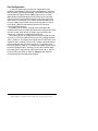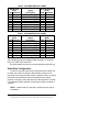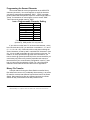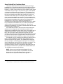
1
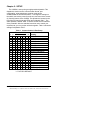
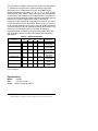
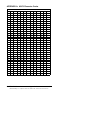
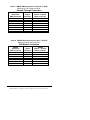
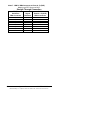
Smart Switch Model 232SS2 Document No. 232SS21600 This product Designed and Manufactured of domestic and imported parts by International Headquarters B&B Electronics Mfg. Co. Inc. 707 Dayton Road -- P.O. Box 1040 -- Ottawa, IL 61350 USA Phone (815) 433-5100 -- General Fax (815) 433-5105 Home Page: www.bb-elec.com Sales e-mail: [email protected] -- Fax (815) 433-5109 [email protected] -- Fax (815) 433-5104 Technical Support e-mail: 1992 B&B Electronics -- Revised April 2000 232SS21600 Manual Cover Page B&B Electronics Mfg Co Inc – 707 Dayton Rd - PO Box 1040 - Ottawa IL 61350 - Ph 815-433-5100 - Fax 815-433-5104 B&B Electronics RESERVED. No part of this publication may be reproduced or transmitted in any form or by any means, electronic or mechanical, including photography, recording, or any information storage and retrieval system without written consent. Information in this manual is subject to change without notice, and does not represent a commitment on the part of B&B Electronics. B&B Electronics shall not be liable for incidental or consequential damages resulting from the furnishing, performance, or use of this manual. All brand names used in this manual are the registered trademarks of their respective owners. The use of trademarks or other designations in this publication is for reference purposes only and does not constitute an endorsement by the trademark holder. TABLE OF CONTENTS Chapter 1: INTRODUCTION...............................................1 Checklist.................................................................................2 Chapter 2: SETUP ...............................................................3 Port Configuration ..................................................................4 Serial Data Configuration .......................................................5 Smart Switch Operation .........................................................6 Programming the Second Character .....................................7 Binary File Transfer................................................................7 Smart Switch/Port Combiner Mode........................................8 Specifications .......................................................................11 Chapter 3: SOFTWARE....................................................12 Introduction ..........................................................................12 Windows SSwitch.................................................................12 DOS SSTSR ........................................................................13 Parameters...........................................................................15 Default Values......................................................................16 Help Screen .........................................................................16 Un-Install ..............................................................................16 Selecting Ports .....................................................................16 Hot Key Method....................................................................17 Command Line Method........................................................17 APPENDIX A: ASCII Character Codes ........................... A-1 APPENDIX B: Cable Charts ............................................B-1 232SS21600 Manual Table of Contents B&B Electronics Mfg Co Inc – 707 Dayton Rd - PO Box 1040 - Ottawa IL 61350 - Ph 815-433-5100 - Fax 815-433-5104 i Chapter 1: INTRODUCTION The RS-232 Four Port Smart Switch/Port Combiner, Model 232SS2, allows one RS-232 host device to connect to as many as four RS-232 devices. The switch can be controlled in two different ways. The first way is referred to as smart switch mode. In this mode, the switch is controlled by sending a programmable preamble code to the "Master" port of the 232SS2. The other way the switch can be controlled is referred to as port combiner mode. In port combiner mode, a slave port can gain access to the master port by asserting a handshake line. If none of the slave ports have their handshake line asserted, the switch can be controlled using the preamble code. The master port can be configured as a DTE or DCE port by an internal switch setting. If the master port is configured as a DTE port, the four slave ports will become DCE ports. The 232SS2 supports the following signals: TD, RD, RTS, CTS, DSR, DCD, and DTR. The 232SS2 has an enhanced mode which offers special timer features. The timer features can be used to prevent slave devices from receiving preamble commands, inadvertently switching from binary/graphic file transfers, and inactive slave devices from holding control of the master port. The 232SS2 will work with baud rates from 1200 to 115,200 bps; 7 or 8 data bits; even, odd or no parity; and 1 or 2 stop bits (7,N,1 is not allowed). NOTE: The data format and rates mentioned are used to switch the 232SS2. The communication between the devices can use any format or data rate. There are four LED's on the 232SS2 to indicate which port is connected to the master port. The master port has a DB-25S female connector and the slave ports have DB-25S female connectors. The 232SS2 requires 12Vdc at 100ma. which is provided through a 2.5mm power jack. 232SS21600Manual B&B Electronics Mfg Co Inc – 707 Dayton Rd - PO Box 1040 - Ottawa IL 61350 - Ph 815-433-5100 - Fax 815-433-5104 1 Checklist Examine the shipping carton and contents for physical damage. If damage is found, file a claim with the shipper immediately. The following equipment should be in the shipping carton: 1. RS-232 Smart Switch 2. Instruction Manual 3. (2) 3.5" floppy disks If any of the items above are not in the shipping carton contact the shipper immediately. 2 232SS21600 Manual B&B Electronics Mfg Co Inc – 707 Dayton Rd - PO Box 1040 - Ottawa IL 61350 - Ph 815-433-5100 - Fax 815-433-5104 Chapter 2: SETUP The 232SS2 is set up using an eight-position dipswitch. This dipswitch is used to set the communication format, port configuration, smart switch/port combiner mode and to enable/disable the enhanced features. To change the settings on the switch, remove the power from the unit, and remove the screws (2) from the bottom of the 232SS2. The dipswitch is located on the top of the PC board (side with LEDs) and is labeled “SW1.” The other dipswitch, labeled “SW2” is used to set the second character of the preamble. After the switches have been set to match your requirements, you can put the unit back together. Table 1 shows the settings for dipswitch “SW1”. 1 0 1 0 1 0 1 0 1 X X X X X X X X X X Table 1. Communication & Port Setup Dipswitch SW1 2 3 4 5 6 7 8 Setting 0 0 X X X X X 1200 Baud 0 0 X X X X X 2400 Baud 1 0 X X X X X 4800 Baud 1 0 X X X X X 9600 Baud * 0 1 X X X X X 19.2K Baud 0 1 X X X X X 38.4K Baud 1 1 X X X X X 57.6K Baud 1 1 X X X X X 115.2K Baud X X 0 X X X X Enhanced Disabled * X X 1 X X X X Enhanced Enable X X X 0 X X X 8 Data Bits * X X X 1 X X X 7 Data Bits X X X X 0 X X Parity Disabled * X X X X 1 X X Parity Enabled X X X X X 0 X Smart Switch Mode* X X X X X 1 X Port Combiner Mode X X X X X X 0 DCE master port * X X X X X X 1 DTE master port 0 = OFF 1 = ON X = DON'T CARE * = FACTORY DEFAULT 232SS21600Manual B&B Electronics Mfg Co Inc – 707 Dayton Rd - PO Box 1040 - Ottawa IL 61350 - Ph 815-433-5100 - Fax 815-433-5104 3 Port Configuration In order to determine the proper port configuration of the 232SS2, it is necessary to have a basic understanding of the terms DCE and DTE. RS-232 was designed, using DB-25 connectors, for connecting a DTE (Data Terminal Equipment) device to a DCE (Data Communication Equipment) device. Each device will have inputs on pins that correspond to outputs on the same pins of the other device. For example, a DTE device will transmit data out on pin 2 (on a DB-25) and a DCE device will receive data in on pin 2 (on a DB-25). IBM PCs and serial printers are DTE devices, modems are DCE devices. If an IBM PC (DTE device) is going to be connected to the 232SS2 master port, the master port should be configured as a DCE port. If a modem (DCE device) is going to be connected to the master port, it should be configured as a DTE port. The master port can be configured as a DCE port (data received on pin 2) or a DTE port (data received on pin 3) by setting dipswitch “SW1”, position 8. To configure the master port as a DCE port, move dipswitch “SW1”, position 8, to the "OFF" position. When the master port is configured as a DCE port, ports A, B, C, & D will become DTE ports (Refer to Table 2). To configure the master port as a DTE port move dipswitch “SW1”, position 8, to the "ON" position. When the master port is configured as a DTE port, ports A, B, C, & D will become DCE ports (Refer to Table 3). Always power down the smart switch when changing switch settings. 4 232SS21600 Manual B&B Electronics Mfg Co Inc – 707 Dayton Rd - PO Box 1040 - Ottawa IL 61350 - Ph 815-433-5100 - Fax 815-433-5104 Table 2. DCE MASTER PORT CHART Master Port A,B,C & D Ports (DCE) Signal (DTE) Pin# Direction Description Pin# Direction 2 Input Transmit Data (TD) 2 Output 3 Output Receive Data (RD) 3 Input 4 Input Request to Send (RTS) 4 Output 5 Output Clear to Send (CTS) 5 Input 6 Input DCE Ready (DSR) 6 Output 7 GROUND Signal Ground (SG) 7 GROUND 8 Output Recv. Line Detect (DCD) 8 Input 20 Input DTE Ready (DTR) 20 Output Table 3. DTE MASTER PORT CHART Master Port A,B,C & D Ports (DTE) Signal (DCE) Pin# Direction Description Pin# Direction 2 Output Transmit Data (TD) 2 Input 3 Input Receive Data (RD) 3 Output 4 Output Request to Send (RTS) 4 Input 5 Input Clear to Send (CTS) 5 Output 6 Output DCE Ready (DSR) 6 Input 7 GROUND Signal Ground (SG) 7 GROUND 8 Input Recv. Line Detect (DCD) 8 Output 20 Output DTE Ready (DTR) 20 Input The 232SS2 supports the following RS-232 signals: TD, RD, SG, RTS, CTS, DSR, DCD, and DTR. The Smart Switch selects port A as the default port at power up. Serial Data Configuration In order for the host device that is connected to the master port to select any of the four ports, the Smart Switch must be set to match the host's communication format. Dipswitch “SW1” is used to select the communication format of the Smart Switch. Switch positions 1 through 3 select the baud rate. Switch position 5 selects 7 or 8 data bits. Switch position 6 determines if parity is enabled or disabled. NOTE: A data format of 7 data bits, no parity and one stop is not allowed. 232SS21600Manual B&B Electronics Mfg Co Inc – 707 Dayton Rd - PO Box 1040 - Ottawa IL 61350 - Ph 815-433-5100 - Fax 815-433-5104 5 Switch position 8 selects the port configuration, see section titled "Port Configuration". Refer to Table 1. Always power down the smart switch when changing switch settings. Smart Switch Operation Smart Switch mode is selected when dipswitch “SW1” position 7 is “Off.” In Smart Switch mode, the 232SS2 is constantly looking for the three character preamble code by monitoring the data that is being received on the master port from the host device. The 232SS2 requires a three character preamble code to turn on and off a port. The first character must be the ASCII escape character (decimal 27). The second character is user programmable by setting dipswitch “SW2”. “SW2” comes from the factory programmed to the ASCII character STX (decimal 2). The third character should be the ASCII upper case letters "A", "B", "C" or "D" (decimal 65, 66, 67, or 68 respectively) to select those ports. To turn off the selected port the third character should be the ASCII EOT character (decimal 4). For instance, to turn on port B you would send: ESC STX B If you were writing a program in BASIC to control the Smart Switch you would form a string like this: SWB$ = CHR$(27) + CHR$(2) + "B" You could then send SWB$ to select port B. Similar strings could be used for turning on the other ports. To turn off the ports the string might look like this: TOFF$ = CHR$(27) + CHR$(2) + CHR$(4) When you are done with a port you can either select a new one directly or turn off the selected port and then turn on the next one. We recommend that you turn off the selected port before selecting the next one. The turn off command consists of three characters that are non-printing (ESC STX EOT). If port A is selected and you send the command to select port B, all three characters (ESC STX B) will pass through the A port since it is still selected and the letter B will show up on your port A device. For information on preventing command codes from being received by slave devices, refer to the Enhance Mode section. NOTE: There is no delay through the Smart Switch and the data is not buffered. 6 232SS21600 Manual B&B Electronics Mfg Co Inc – 707 Dayton Rd - PO Box 1040 - Ottawa IL 61350 - Ph 815-433-5100 - Fax 815-433-5104 Programming the Second Character The second character comes programmed as the ASCII STX character (decimal 2). You can change this to any 8-bit character you wish by reprogramming dipswitch “SW2”. “SW2” is an eightposition switch with each position equal to a certain weight. Refer to “Setup” for instructions on removing the cover to access “SW2”. Table 4 shows the weight chart for “SW2”. Table 4. Programmable Character Setting Dipswitch SW2* WEIGHT 1 1 2 2 3 4 4 8 5 16 6 32 7 64 8 128 *Factory Default -- ASCII “STX” character (decimal 2), SW2 position 2 is only one ON. If you wish to use the letter "U" as the second character, which has a decimal value of 85, you would turn on switches 1, 3, 5, and 7 (1 + 4 + 16 + 64 = 85). Caution should be used when selecting the second character, so that by itself, or with the ESC character in front of it, it is not a valid command to any of the devices on the port. For instance, on some printers ESC @ is the reset command. If you tried to use the @ symbol (decimal 64) for the second character you could reset your printer every time the preamble code was sent. Note also that if your communication configuration is set for 7 data bits you cannot use the eighth bit of SW2. For a list of the ASCII character codes and their decimal values refer to Appendix A. Binary File Transfer A simple method of using the Smart Switch to transfer binary files without the concern of it accidentally disconnecting, is to set the file transfer at a baud rate different from the baud rate of the Smart Switch. When transferring files at a different baud rate, the Smart Switch will stay connected from the last preamble code. 232SS21600Manual B&B Electronics Mfg Co Inc – 707 Dayton Rd - PO Box 1040 - Ottawa IL 61350 - Ph 815-433-5100 - Fax 815-433-5104 7 Smart Switch/Port Combiner Mode This mode allow Ports A-D to select the master port using a handshake line. It also allows selection from the master port via the preamble code described in the Smart Switch Only Mode section. Position 7 of “SW1” must be ON to be in port combiner mode. When a handshake line goes high on any of the four ports, it will establish a connection from that port to the master port. This works on firstcome-first-serve basis. If multiple ports have their handshake lines high, the port that has been waiting the longest will be next to be connected to the master port. For example, (Initial conditions -- no slave ports with handshake lines asserted.) in chronological order, Port C asserts its handshake line, Port A asserts its handshake line, Port D asserts its handshake line and then Port C disasserts its handshake line. When Port C asserts its handshake line, a connection will be made between the master port and Port C. When Port C disasserts its handshake line, Port C will be disconnected and Port A will be connected to the master port. When Port A disasserts its handshake, Port A will be disconnected and Port D will be connected to the master port. The handshake line that is used to connect to the master port depends on the configuration of the master port (which in turn determines the configuration of the slave ports). If the master port is configured as a DTE port, then the slave ports are configured as DCE, and RTS must be raised by the device (which is DTE) to connect to the master port. If the master port is configured as a DCE port, then the slave ports are configured as DTE and CTS must be raised by the device (which is DCE) to connect to the master port. For example, port A is configured as a DCE port (slave device is DTE), in order to establish a connection to the master port, the device must set RTS high (assert). The 232SS2 would recognize this as a prompt for connection to the master port. The connection would be dropped as soon as RTS from the device is lowered. The devices on ports B-D may raise RTS at any time to request a connection. However, if port A is connected to the master port, any data sent from the devices on ports B-D to the 232SS2 will be lost. The 232SS2 does not have any buffering. NOTE: When a port is selected via the Master Port, the handshake lines will be ignored until the Master Port sends the turn off code. When the Master Port is selected by a handshake line, all preamble codes will be ignored. 8 232SS21600 Manual B&B Electronics Mfg Co Inc – 707 Dayton Rd - PO Box 1040 - Ottawa IL 61350 - Ph 815-433-5100 - Fax 815-433-5104 A typical application would be to have RTS and CTS tied together on the master port. When RTS (assuming DTE slave device) on port A (configured as DCE) is asserted, CTS on port A will be asserted when a connection is established. If a port is not connected to the master port, then CTS on that port will remain low. Therefore, a port can monitor the handshake line to determine if a connection has been established. Enhanced Mode -- Timer Features The 232SS2 has an enhanced mode, which offers special timer features. The timer features can be used to prevent slave devices from receiving preamble commands, inadvertent switching from binary/graphic file transfers, and inactive slave devices from holding control of the master port. The timer has two different modes: an inactivity mode and an inadvertent switch mode. When in inactivity mode, the 232SS2 will monitor the data lines. If there is no activity for the specified time, the selected slave port will be disconnected from the master port. When in inadvertent switch mode, the 232SS2 will ignore switching commands for the specified period of time. After this time has expired, the selected slave port will be disconnected from the master port. The timer functions are enabled via a dipswitch setting and through software commands. Dipswitch SW1 position 4 must be ON for the 232SS2 to be in enhanced mode. The software commands follow the same format as preamble codes used for switching. There are two commands used to set the timer functions: Set Timer Mode and Set Timer Value. These commands require an additional byte for data. The Set Timer Value command requires the third byte to be an ASCII “T” character. The data byte (fourth byte) must be a value between ASCII “0” and ASCII “9”. A value of “0” is used to disable the timer. Refer to Table 3 for timer values. For example, sending the following string to the 232SS2 will set the timer value to 5 seconds (assuming programmable character is the factory default of 2). SetTV$ = CHR$(27) + CHR$(2) +”T” + “6” The “T” tells the 232SS2 it is the set timer value command and the “6” indicates which timer value to use. 232SS21600Manual B&B Electronics Mfg Co Inc – 707 Dayton Rd - PO Box 1040 - Ottawa IL 61350 - Ph 815-433-5100 - Fax 815-433-5104 9 Table 3 - Timer Values Data Byte Value 0 1 2 3 4 5 6 7 8 9 timer disabled 10ms 25ms 100ms 500ms 1s 5s 30 s 1 min. 5 min. The Set Timer Mode command requires the third byte to be an ASCII “M”. If the data byte (fourth byte) is an ASCII “0”, zero (default), the timer will be setup as an inactivity timer. For example: Sending the following string to the 232SS2 will set up the timer as an inactivity timer (assuming programmable character is the factory default of 2). SetTM$ = CHR$(27) + CHR$(2) +”M” + “0” The “M” tells the 232SS2 it is the set timer mode command and the “0” indicates to set up the timer as a inactivity timer. When the timer is configured as an inactivity timer, the 232SS2 will monitor the data lines (TD & RD) for data. If there is no activity for the specified timer value, the slave port that is connected to the master port will be disconnected. In smart switch mode, the inactivity timer can be used to prevent the preamble codes from being received by the slave devices. In port combiner mode, the inactivity timer can be used to prevent devices from tying up the master port. For example (port combiner mode), all the slave ports have their handshake lines asserted. The device on Port C has its handshake line asserted and is currently connected to the master port, but has not been transmitting or receiving data. When the inactivity timer expires, Port C will be disconnected and the next slave port will then be connected to the master port (following the first-come-first-serve rule). Port C will then be placed at the “end of the line”. If the data byte of the Set Timer Mode command is an ASCII “1”, the timer will be setup to ignore switching commands. Sending the following string to the 232SS2 will set up the timer to ignore switching commands. (Assuming programmable character is the factory default of 2). SetTM$ = CHR$(27) + CHR$(2) +”M” + “1” 10 232SS21600 Manual B&B Electronics Mfg Co Inc – 707 Dayton Rd - PO Box 1040 - Ottawa IL 61350 - Ph 815-433-5100 - Fax 815-433-5104 The “M” tells the 232SS2 it is the set timer mode command and the “1” indicates to set up the timer to ignore switching commands. When the timer is configured in this mode, the 232SS2 will not accept any switching commands (“A”, ”B”, ”C”, ”D”, or “EOT”) for the specified timer value. After the timer has expired, the slave port that is connected to the master port will be disconnected. This feature is useful to prevent inadvertent switching during binary/graphic type file transfers. For example (smart switch mode): The timer is configured to ignore switching commands for 5 seconds. The select Port D command is sent to the 232SS2. Once Port D is connected a file of unknown data type (so file may or may not contain a switching command sequence) is to be transferred through the 232SS2. For a period of 5 seconds after Port D is connected, no switching commands will be accepted. As long as the file transfer takes less than 5 seconds, there is no chance the 232SS2 will inadvertently switch ports. Table 4 - 232SS2 Commands Command Characters 2nd 3rd 4th Function 1st Select Port A ESC X* “A” Comments NU** Switching Command Select Port B ESC X* “B” NU** Switching Command Select Port C ESC X* “C” NU** Switching Command Select Port D ESC X* “D” NU** Switching Command Deselect Port ESC X* EOT NU** Switching Command Set Timer Value ESC X* “T” “0”-”9” Enhanced Mode Set Timer Mode ESC X* “M” “0”,”1” Enhanced Mode *X represents the programmable character set by dipswitch SW2 **NU = Not Used Specifications 232SS2 Model: 6.2 x 8.0 x 2.5hin Size: Power: 12Vdc to 16Vdc @ 100mA 232SS21600Manual B&B Electronics Mfg Co Inc – 707 Dayton Rd - PO Box 1040 - Ottawa IL 61350 - Ph 815-433-5100 - Fax 815-433-5104 11 Chapter 3: SOFTWARE Introduction The 232M`SS2 comes with two application programs that can be used to switch between ports. Each comes on a separate floppy disk. Either can be used independently as the final application or for testing the functionality of the hardware. The SSwitch program is a Windows program that allows you to switch ports with buttons on a Windows interface, or from the DOS command line. It will run on Windows 95, 98, or Windows NT 4.0 with service pack 3 installed. When the software is installed, an example file, SSWVb6.txt, is also placed in the same directory. This is a text file with Visual Basic sample code. It gives examples on how to open the port, assemble switching commands, and send them out the port. It can be accessed by selecting START/PROGRAMS/B&B Electronics/SSWITCH/Sample Code. The Smart Switch, Terminate and Stay Resident (SSTSR) Program (IBM PC or Compatible), is a DOS only application which allows the user to change Smart Switch ports either through the command line or by hitting a sequence of keys at the same time, referred to as hot keys. SSTSR program requires 1K of memory. Windows SSwitch Installation To install the SSwitch Program (Windows 95/98 & NT) • From START/ SETTINGS/ CONTROL PANEL • Select Add/Remove Programs • Insert the Smart Switch for Windows disk and select Install • Follow the Installation prompts to complete the installation Running SSwitch The SSwitch program can be launched from the desktop shortcut or from the Start/Programs/B&B Electronics/SSwitch directory if the default directory was selected during installation. The Smart Switch software configuration can be changed in the SSwitch program by selecting Ports/Configuration from the menu. You change port selection by clicking on the option box or by using the up/down arrow keys. The port selection can also be changed at the command line by typing SSwitch and the letter representing that port. For example, to change to port B you would enter SSwitch B at the command line. The letter N (none) is used to close all the ports. 12 232SS21600 Manual B&B Electronics Mfg Co Inc – 707 Dayton Rd - PO Box 1040 - Ottawa IL 61350 - Ph 815-433-5100 - Fax 815-433-5104 To Uninstall SSwitch.exe • • • • From START/ SETTINGS/ CONTROL PANEL Select Add/ Remove Programs Select SSwitch from the list of programs Click on the Add/Remove button DOS SSTSR Installation To Install the SSTSR Program (DOS) If A drive is your floppy drive: • • • Place the Smart Switch for DOS disk in drive A At the DOS prompt Type a:\INSTALL.exe and press the ENTER key. The following files will be located on your hard drive: 1)SSTSR.EXE - The executable file for the Smart Switch. 2)SETUP.EXE - Configuration program for the SSTSR. There are two methods to begin the SSTSR program. The first and preferred way is to use the SETUP.EXE program and the second is through the SSTSR.COM file. 1) SETUP.EXE Method (preferred) If the software was installed on your hard drive follow these steps: • Type C: and press the ENTER key. • Type CD\SS and press the ENTER key. To begin the SSTSR program follow these steps: • Type SETUP and press the ENTER key. You will be prompted for parameters (for a description refer to the Parameters section) that are necessary for the SSTSR to communicate with the Smart Switch. The value in [ ] are the default values. If this value is desired, just press the ENTER key. 232SS21600 Manual B&B Electronics Mfg Co Inc – 707 Dayton Rd - PO Box 1040 - Ottawa IL 61350 - Ph 815-433-5100 - Fax 815-433-5104 13 Enter Port Address [02F8]: Enter Baud Rate ( 1 = 150 2 = 300 3 = 600 4 = 1200 5 = 24006 = 4800 7 = 9600 8 = 19200) [7]: Enter Parity (0 = No 1 = Odd 2 = Even) [0]: Enter Number of Data Bits ( 7 = Seven Data Bits 8 = Eight Data Bits) [8]: Enter Smart Switch Second Char (Decimal Value) [2]: Enter Hot Key Sequence (1 = <LftShift><Alt><A|B|C|D|N> 2 = <Rht Shift><Alt><A|B|C|D|N> 3 = <Lft Shift><Alt><1|2|3|4|N> 4 = <Rht Shift><Alt><1|2|3|4|N> 5 = <CTRL><ALT><A|B|C|D|N> 6 =<CTRL><ALT><1|2|3|4|N>)[1]: At this point a file called GO.BAT will be created. • Type GO and press the ENTER key. Once the GO.BAT file is created, every time you wish to begin the SSTSR all that you need to do is type GO and press the ENTER key. If you need to change any of the settings of the SSTSR simply run the SETUP.EXE program again to create a new GO.BAT file. 2) SSTSR.EXE Method The SSTSR.EXE method requires the same parameters (for a description refer to the Parameters section) as the SETUP.EXE method, except that they are all specified through the command line. Each of these parameters begins with a command symbol followed by an option as defined in the following table. Command Description Options A or a B or b Port Address Baud Rate D or d Number of Data Bits Parity User Defined Char. Hot Key P or p U or u H or h 14 Hexadecimal Address (0 - FFFFh) 1 = 150 2 = 300 3 = 600 4 = 1200 5 = 2400 6 = 4800 7 = 9600 8 = 19200 7 = 7 Data Bits 8 = 8 Data Bits 0 = No 1 = Odd 2 = Even Decimal (0 - 255) 1 = <Left Shift><ALT><A|B|C|D|N> 2 = <Right Shift><ALT><A|B|C|D|N> 3 = <Left Shift><ALT><1|2|3|4|N> 4 = <Right Shift><ALT><1|2|3|4|N> 5 = <CTRL><ALT><A|B|C|D|N> 6 = <CTRL><ALT><1|2|3|4|N> 232SS21600 Manual B&B Electronics Mfg Co Inc – 707 Dayton Rd - PO Box 1040 - Ottawa IL 61350 - Ph 815-433-5100 - Fax 815-433-5104 If the software was installed in the default directory: • At the DOS prompt Type C: and press the ENTER key. • Type CD\232MSS2 and press the ENTER key. To begin the SSTSR program (the following will be used as an example): Port Address = 03F8 Parity = Odd Baud = 9600 User Defined Char. = 8 Data Bits = 8 Hot Key Sequence = 4 • Type SSTSR A03F8 B7 D8 P1 U8 H6 and press the ENTER key. Using this method, every time you want to install the SSTSR with different parameter settings than the default (refer to the Default Values section), the missing parameter must be specified. Parameters The Port Address is the address where the serial communications port is located. Some of the typical port addresses are as follows: Port Address COM 1 03F8h COM 2 02F8h COM 3 03E8h COM 4 02E8h The Baud Rate is the speed at which communication takes place between the SSTSR and the Smart Switch. It must be specified so that it is equal to SW1 on the Smart Switch. The Number of Data Bits is the length of each character that gets sent from the SSTSR to the Smart Switch. This value must be specified so that it is equal to SW2 on the Smart Switch. The Parity is a method of error detection that takes place during the transmission of data between the SSTSR and the Smart Switch. This value must be specified so that it is equal to SW2 on the Smart Switch. The User Defined Character must be set so that it is equal to SW3 on the Smart Switch. 232SS21600 Manual B&B Electronics Mfg Co Inc – 707 Dayton Rd - PO Box 1040 - Ottawa IL 61350 - Ph 815-433-5100 - Fax 815-433-5104 15 The Hot Key is a sequence of three keys that must be pressed simultaneously to switch from one Smart Switch Port to another. For example, the hot key sequence, <Left Shift> <ALT> <A|B|C|D|N> states that the left shift, Alt, and either A, B, C, D, or N must be pressed at the same time to select the corresponding Smart Switch Port. N turns off all Smart Switch ports. Default Values If you type SSTSR on the command line with no parameters, or omit any parameters, the default value of the missing parameter will be used. The default values are: Description Default Value 02F8h (COM 2) Port Address 7 = 9600 Baud Rate 0 = No Parity Parity 8 = 8 Data Bits Data Bits 2 = STX (CTRL B) Second Character Hot Key Sequence 1 = <Left Shift><ALT><A|B|C|D|N> Help Screen If you are installing the SSTSR using the SSTSR.COM method, you can type SSTSR ? and press the ENTER key to obtain a list of the commands and their options. Un-Install The SSTSR may be un-installed easily by typing SSTSR - and pressing the ENTER key. In some cases the SSTSR will not uninstall. This may be caused by another terminate and stay resident (TSR) being installed after it. To un-install the SSTSR when this occurs, the other TSR must first be un-installed, then the SSTSR can be un-installed normally. Selecting Ports There are two different ways in which a Smart Switch port is selected, either through the command line or by pressing the predefined hot key sequence after the SSTSR was installed. When a request to change ports is made, using either method, first the current port is turned off, then the port selected is turned on. The two methods are described as follows: 16 232SS21600 Manual B&B Electronics Mfg Co Inc – 707 Dayton Rd - PO Box 1040 - Ottawa IL 61350 - Ph 815-433-5100 - Fax 815-433-5104 Hot Key Method This method enables the user to select any Smart Switch port by pressing a predefined sequence of keys at the same time after the SSTSR is installed (refer to Program Installation). Example: If Hot Key sequence <Lft Shift><Alt><A|B|C|D|N> was selected, to change ports you would press at the same time: Left Shift - Alt - A ..... to select port A Left Shift - Alt - B ..... to select port B Left Shift - Alt - C ..... to select port C Left Shift - Alt - D ..... to select port D Left Shift - Alt - N ..... to turn off all ports Command Line Method This method enables the user to select any Smart Switch port through the command line. To specify a Smart Switch port through the command line, you would type SSTSR followed by the X command symbol and the letter of the port. Example: To change to Smart Switch port '"C" you would type SSTSR XC at the Dos prompt and press the ENTER key. Before a Smart Switch port is changed, a check is made to determine if the port is busy transmitting. If the port is busy the STSR will generate a tone to notify you that the port is busy and that a port change cannot be made. CAUTION: If the software package you are using for transmission is running at a fast baud rate (57600), the SSTSR may not detect the Smart Switch port as busy and the transmission could be interrupted. The SSTSR does not detect when the Smart Switch port is receiving data. Therefore, if data is being received, the Smart Switch port may still be changed. 232SS21600 Manual B&B Electronics Mfg Co Inc – 707 Dayton Rd - PO Box 1040 - Ottawa IL 61350 - Ph 815-433-5100 - Fax 815-433-5104 17 APPENDIX A: ASCII Character Codes DECIMAL to HEX to ASCII CONVERSION TABLE DEC HEX ASCII KEY DEC HEX ASCII DEC HEX ASCII DEC HEX ASCII 0 0 NUL ctrl @ 32 20 SP 64 40 @ 96 60 ` 1 1 SOH ctrl A 33 21 ! 65 41 A 97 61 a 2 2 STX ctrl B 34 22 “ 66 42 B 98 62 b 3 3 ETX ctrl C 35 23 # 67 43 C 99 63 c 4 4 EOT ctrl D 36 24 $ 68 44 D 100 64 d 5 5 ENQ ctrl E 37 25 % 69 45 E 101 65 e 6 6 ACK ctrl F 38 26 & 70 46 F 102 66 f 7 7 BEL ctrl G 39 27 ' 71 47 G 103 67 g 8 8 BS ctrl H 40 28 ( 72 48 H 104 68 h 9 9 HT ctrl I 41 29 ) 73 49 I 105 69 i 10 A LF ctrl J 42 2A * 74 4A J 106 6A j 11 B VT ctrl K 43 2B + 75 4B K 107 6B k 12 C FF ctrl L 44 2C , 76 4C L 108 6C l 13 D CR ctrl M 45 2D - 77 4D M 109 6D m 14 E SO ctrl N 46 2E . 78 4E N 110 6E n 15 F SI ctrl O 47 2F / 79 4F O 111 6F o 16 10 DLE ctrl P 48 30 0 80 50 P 112 70 p 17 11 DC1 ctrl Q 49 31 1 81 51 Q 113 71 q 18 12 DC2 ctrl R 50 32 2 82 52 R 114 72 r 19 13 DC3 ctrl S 51 33 3 83 53 S 115 73 s 20 14 DC4 ctrl T 52 34 4 84 54 T 116 74 t 21 15 NAK ctrl U 53 35 5 85 55 U 117 75 u 22 16 SYN ctrl V 54 36 6 86 56 V 118 76 v 23 17 ETB ctrl W 55 37 7 87 57 W 119 77 w 24 18 CAN ctrl X 56 38 8 88 58 X 120 78 x 25 19 EM ctrl Y 57 39 9 89 59 Y 121 79 y 26 1A SUB ctrl Z 58 3A : 90 5A Z 122 7A z 27 1B ESC ctrl [ 59 3B ; 91 5B [ 123 7B { 28 1C FS ctrl \ 60 3C < 92 5C \ 124 7C | 29 1D GS ctrl ] 61 3D = 93 5D ] 125 7D } 30 1E RS ctrl ^ 62 3E > 94 5E ^ 126 7E ~ 31 1F US ctrl _ 63 3F ? 95 5F _ 127 7F DEL 232SS21600 Manual Appendix A B&B Electronics Mfg Co Inc – 707 Dayton Rd - PO Box 1040 - Ottawa IL 61350 - Ph 815-433-5100 - Fax 815-433-5104 A-1 APPENDIX B: Cable Charts All charts will indicate if the Master Port of the 232SS2 should be configured as a DCE port or a DTE port. Refer to the Port Configuration section of the manual for information on Master Port configurations. Chart 1. IBM PC DB25 Connector to Master Port Straight Through Connection IBM PC Serial Port DB25 Connector 2 3 4 5 6 7 8 20 Signal Direction -----------> <---------------------> <----------<----------GROUND <---------------------> 232SS2 Master Port (DCE) DB25 Connector 2 3 4 5 6 7 8 20 Chart 2. IBM PC DB9 Connector to Master Port Straight Through Connection IBM PC Serial Port DB9 Connector 1 2 3 4 5 6 7 8 232SS21600 Manual Signal Direction <----------<---------------------> -----------> GROUND <---------------------> <----------- 232SS2 Master Port (DCE) DB25 Connector 8 3 2 20 7 6 4 5 Appendix C B&B Electronics Mfg Co Inc – 707 Dayton Rd - PO Box 1040 - Ottawa IL 61350 - Ph 815-433-5100 - Fax 815-433-5104 C-1 Chart 3. Modem DB25 Connector to Master Port Straight Through Connection Async Modem Serial Port DB25 Connector 2 3 4 5 7 8 20 Signal Direction <---------------------> <---------------------> GROUND -----------> <----------- 232SS2 Master Port (DTE) DB25 Connector 2 3 4 5 7 8 20 Chart 4. IBM PC DB25 Connector to Ports A - D (DTE) Master port DCE, Slave port DTE. Null Modem Connection IBM PC Serial Port DB25 Connector 2 3 4 5 6&8 7 20 C-2 Signal Direction -----------> <---------------------> <---------<---------GROUND -----------> Appendix C 232SS2 Ports A - D (DTE) DB25 Connector 3 2 5 4 20 7 6&8 232SS21600 Manual B&B Electronics Mfg Co Inc – 707 Dayton Rd - PO Box 1040 - Ottawa IL 61350 - Ph 815-433-5100 - Fax 815-433-5104 Chart 5. IBM PC DB25 Connector to Ports A - D (DCE) Master port DTE, Slave ports DCE. Straight Through Connection IBM PC Serial Port DB25 Connector 2 3 4 5 6 7 8 20 Signal Direction -----------> <---------------------> <----------<----------GROUND <---------------------> 232SS2 Ports A - D (DCE) DB25 Connector 2 3 4 5 6 7 8 20 . Chart 6. IBM PC DB9 Connector to Ports A - D (DTE) Master port DCE, Slave port DTE. Null Modem Connection IBM PC Serial Port DB9 Connector 1&6 2 3 4 5 7 8 232SS21600 Manual Signal Direction <----------<---------------------> -----------> GROUND -----------> <----------- 232SS2 Ports A – D (DTE) DB25 Connector 20 2 3 6&8 7 5 4 Appendix C B&B Electronics Mfg Co Inc – 707 Dayton Rd - PO Box 1040 - Ottawa IL 61350 - Ph 815-433-5100 - Fax 815-433-5104 C-3 Chart 7. IBM PC DB9 Connector to Ports A - D (DCE) Master port DTE, Slave port DCE. Straight Through Connection IBM PC Serial Port DB9 Connector 1 2 3 4 5 6 7 8 C-4 Signal Direction <----------<---------------------> -----------> GROUND <---------------------> <----------- Appendix C 232SS2 Ports A – D (DCE) DB25 Connector 8 3 2 20 7 6 4 5 232SS21600 Manual B&B Electronics Mfg Co Inc – 707 Dayton Rd - PO Box 1040 - Ottawa IL 61350 - Ph 815-433-5100 - Fax 815-433-5104 FEDERAL COMMUNICATIONS COMMISSION RADIO FREQUENCY INTERFACE STATEMENT Class A Equipment This equipment has been tested and found to comply with the limits for Class A digital device, pursuant to Part 15 of the FCC Rules. These limits are designed to provide reasonable protection against harmful interference when the equipment is operated in a commercial environment. This equipment generates, uses, and can radiate radio frequency energy and, if not installed and used in accordance with the instructions, may cause harmful interference to radio communications. Operation of this equipment in a residential area is likely to cause harmful interference, in which case the user will be required to correct the interference at personal expense. FCC Class A Equipment Statement