1
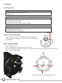
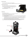
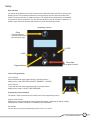
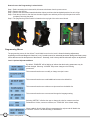
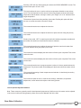
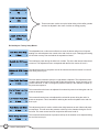
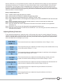
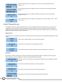
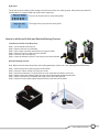
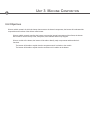
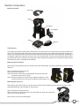
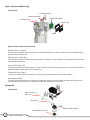
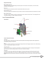
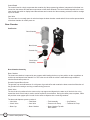
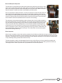
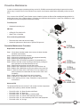
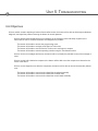
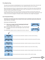
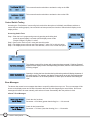
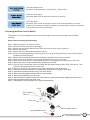
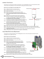
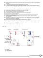
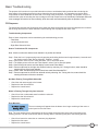
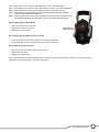
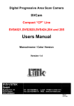
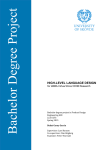
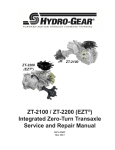
BUNN® TECHNICAL TRAINING
trifecta™
Index
Unit 1: Installation
Site Requirements............................................................................................................... 4
Location of the Serial Number........................................................................................... 4
Water Supply Installation.................................................................................................... 4
Electrical Install................................................................................................................... 5
Initial Start-Up...................................................................................................................... 5
Unit 2: Setup
User Interface....................................................................................................................... 7
Levels of Programming....................................................................................................... 7
Programming Lockout Switch..................................................................................... 7
Level 1 Programming................................................................................................... 8
Level 2 Programming................................................................................................... 9
Brew Water Calibration....................................................................................................... 11
Adjusting Brew Parameters................................................................................................ 11
Brewing Process................................................................................................................. 12
Wetting Phase............................................................................................................... 12
Extraction...................................................................................................................... 12
Hydrolysis...................................................................................................................... 13
How to Load Ground Coffee............................................................................................... 13
How to Start the Brewing Process..................................................................................... 13
Unit 3: Machine Composition
Exterior Overview................................................................................................................ 15
The Enclosure............................................................................................................... 15
Removing the Front Panel........................................................................................... 15
Removing Top Cover.................................................................................................... 15
Upper Component Mounting Assembly............................................................................ 16
Sprayhead Assembly.......................................................................................................... 16
Lower Component Mounting Assembly............................................................................ 17
Brew Chamber Assembly................................................................................................... 18
Brew & Dispense Sequence . ...................................................................................... 18
Rinse Sequence............................................................................................................ 19
Unit 4: Preventive Maintenance
PM Parts............................................................................................................................... 21
Preventive Maintenance Procedure................................................................................... 21
Replacement of the O-Rings........................................................................................ 21
Advanced PM................................................................................................................ 21
Unit 5: Troubleshooting
Load Component Testing................................................................................................... 23
Control Switch Testing........................................................................................................ 24
Error Messages.................................................................................................................... 24
Accessing the Brew Lockout Switch................................................................................. 25
Hot Water Tank Removal..................................................................................................... 26
Control Board Removal and Replacement........................................................................ 26
Triac Map.............................................................................................................................. 27
Schematic Wiring Diagram................................................................................................. 28
Fill Sequence Components................................................................................................ 29
Turbulent Brew Time Sequence Components.................................................................. 30
Press-Out Sequence Components.................................................................................... 30
Rev. A
© 2009 Bunn-O-Matic Corporation. All Rights Reserved
Unit 1 Installation
Unit Objectives
Given a realistic scenario depicting a new site install, the learner will be able to install and setup the trifecta coffee
brewer for customer turnover without error.
Given a new trifecta, all the necessary tools and safety equipment, the learner will be able to install the brewer without error.
The learner will be able to verify that the site requirements have been met.
The learner will be able to locate and document the serial number.
The learner will be able to hook up the water supply.
The learner will be able to hook up the electrical supply.
The learner will be able to power on the brewer.
The learner will be able to perform initial setup.
Installation
Site Requirements
Space
• trifecta dimensions are 23” H x 12” W x 12” D
• Weight 35 lbs
Plumbing
• 1/4 male flare fitting
• Dedicated water supply with shut-off
• Connected to cold water supply
• Water pressure 20-90psi, 50psi if regulator is needed
Electrical
• 120VAC, 2 wire plus ground
• Dedicated 15Amp circuit breaker
• Receptacle within 5 feet of the brewer
Number
DataSerial
Plate/Serial
Number
Location of the Serial Number
The serial number is located on the data plate which is located on the
inside of the brewer. The serial number half tag can be found underneath
the switch panel.
Water Supply Installation
Step 1: Flush water lines.
Step 2: Securely attach 1/4” water supply line to the elbow.
Step 3: Secure the water supply line and power cord under the retainer strap in any of the three locations as needed.
Step 4: Turn on the water supply.
3
1
2
Water Line and Power Cord Entrance Locations
4
trifecta™ Training Manual
Electrical Install
Step 1: Use a voltmeter to verify the correct voltage supply.
Step 2: The brewer must be disconnected or unplugged until specified in the initial setup section.
Optional Drain Hook-up
Step 1: Remove the drip tray and the chrome plug from the base.
Step 2: Drill out the auxiliary outlet on the drip tray with a 1/2” drill bit.
Step 3: Secure a 5/8” hose to the drip tray; routing it through the
opening in the base assembly.
Step 4: Connect the hose to the drain line as needed.
Step 5: Install the drip tray.
Initial Setup
Step 1: Install the check valve.
Step 2: Install the clear brew chamber, brew cup and then lock into position.
Step 3: Place an empty container under the brew chamber.
Step 4: Connect the brewer to the power source.
Step 5: Press the brew start switch and allow the water to flow into the brew tank. Some excess water will flow into the receiving container.
Step 6: Wait approximately five minutes for the water in the tank to heat to the proper temperature. The display will read “HEATING” until the tank reaches it’s operating temperature. Some water will drip from the brew
chamber during this time; this is due to expansion and should not occur thereafter. Any excess water in the brew chamber will be purged automatically at the end of the initial setup.
Step 7: Water volumes and flow settings have been preset at factory default. Refer to the “Adjusting Brewing
Parameters” section of the “Installation & Operating Guide” if the parameters need to be adjusted.
Step 8: If the instruction in this section was followed correctly, the brewer is now ready for use.
Brew Chamber
Check Valve
Brew Cup
5
Bunn-O-Matic Corporation
Unit 2 Setup
Unit Objectives
Given a realistic scenario depicting a new site install, the learner will be able to install and setup the trifecta coffee
brewer for customer turnover without error.
Given an installed trifecta, all the necessary tools and safety equipment, the learner will be able to setup the brewer for initial operation.
The learner will be able operate the switch controls.
The learner will be able to enter the programming menus.
The learner will be able to perform the flow-rate calibration of the brew water.
The learner will be able to adjust the brewing parameters and perform a brew process.
The learner will be able to adjust optional program menu settings.
Setup
User Interface
The switch decal adheres to the front housing over the electronic switch and LCD (Liquid Crystal
Display) board. The mechanical switches are mounted directly onto the electronic board with a
button mounted on the stem for product actuation. The switch decal overlay buttons are identified
by symbols for button recognition. The user interface allows the user to program the brewer for a
product recipe, start brew process and to perform a rinse after the brew process.
Operating Controls
Rinse
Press this button to
rinse the brew chamber
after each brew cycle.
(+)/YES
(-)/NO
Brew Start
Program/Select
Press again to cancel.
Levels of Programming
Level 1 Access
Press and hold both arrows approximately 3 seconds until the
display screen reads “RECIPE CHANGES” “ENABLED - LOCKED”.
Level 2 Access
Press and hold both arrows approximately 10 seconds until the
display screen reads “ PAUSE % BEFORE BUBB”.
Programming Lockout Switch
The switch is used to prevent access to both levels of the programming menus.
Program Lock Position
When trying to access either level of the programming menus, a message will display reading
“MEMORY IS LOCKED CONSTANT CHANGE IS NOT POSSIBLE”.
Set Position
You are able to access the programming menus in level 1 or level 2.
7
Bunn-O-Matic Corporation
How to Access the Programming Lockout Switch
Step 1: Before accessing the lockout switch, disconnect the brewer from the power source.
Step 2: Remove the drip tray.
Step 3: Remove the two screws located behind the drip tray and lower the backsplash panel as far as it will go.
Step 4: Push the top down to clear the brew chamber support arm and then pull the top of the panel out before
completely removing the panel.
Step 5: The programming lockout switch is located on the top right of the main control board.
Programming Menus
The programming menus for the trifecta™ are divided into two levels. Level 1 allows for brewing adjustments,
supporting services and diagnostic functions. Level 2 contains menus for advanced parameter settings and factory setup
menus that are used in development of the trifecta™. Generally, level 2 factory default values will require no adjustment.
Level 1 Optional Adjustment Menus
By default, “ENABLED” will be flashing to indicate that the brewing parameters may be accessed and changed. Selecting “LOCKED” will prevent changes to the brewing
parameters.
This screen allows the user to modify or change a recipe’s name.
This screen allows the user to add additional names to the default list.
This screen allows the user to delete a recipe name from the default list.
This screen allows the user to access and change the language setting.
Selecting “METRIC” will allow the user to change the units for measurement from
Fahrenheit to Celsius; ounces to milliliters; etc. “ENGLISH” is the default setting.
When enabled, this will allow different temperatures for recipes and will disable the “BREW LOCKOUT” screen. The default setting is “DISABLED”.
8
trifecta™ Training Manual
Selecting “YES” will only allow brewing at or above the “READY DEGREES” screen. The default of this option is set to “YES”.
The screen allows the user to set the minimum temperature allowable to start a brew cycle. The set temperature on this screen is how many degrees under the tank target temperature that the brewer can begin a brew cycle. Range of 2° to 20° below the tank target temperature.
The amount of press time during auxiliary rinse mode. Enabling this option will allow the user to set the seconds for rinse time. Range
This screen allows the user to adjust the rinse time.
This screen allows the user to adjust the amount of press out time during the primary rinse mode.
Primary rinse mode. “OFF” is equal to push and hold. Numbers represent seconds and the brewer will continue to rinse when the button is released.
This screen allows the user to adjust the amount of pressure used to exit water from the brew chamber during the primary rinse mode.
This screen will track and display the total number of brew cycles completed. This screen cannot be reset.
This screen will track and display the total number of brew cycles completed. This screen can be reset.
This screen allows the user to program a phone number of a factory authorized service department. This phone number will be displayed if the brewer should encounter a fault code.
This screen allows testing of load components and switches. It should only be used by
trained technicians.
This screen will allow the user to reset all brew settings, calibrations, temperature
adjustments, coffee names and recipes to the factory presets.
Level 2 Optional Adjustment Menus
Note: These menus are generally used for developmental purposes only. While some of the menus can be adjusted
in the event of coffee not mixing properly, others are not to be adjusted at all in the field.
Brew Water Calibration
9
Bunn-O-Matic Corporation
These menus are used to set up the initial mixing of the coffee grounds
and can be adjusted in the event of coffee not mixing properly.
Do Not Adjust: Factory Setup Menus
The adjustable time on this screen effects how soon the brewer will go from full power heating to a reduced power triac control at the end of a brew cycle. Changing this setting will slow the recovery time and reduce the expansion of water.
The turbulence power during the initial mix of coffee. This is the first interval when the air comes on. This adjustment menu corresponds with the first four menus in Level 2.
This adjustment menu is the power level of the turbulence when the brewer is in the off time during a brew cycle.
The time that the turbulence pump is on right before a dispense. This adjustment menu is used to help clear the brew screen and aid the initial press-out. It also can work in con
junction with items 11 and 12 to begin the pressure build up in the chamber to speed up the press-out sequence.
This screen allows the time to be adjusted for reduced air power level during the end of a press-out sequence.
This screen allows the time to be adjusted for reduced air power during the end of a press-out sequence. This is intended for reducing the amount of splatter at the end of a brew cycle.
This adjustment menu is used to minimize the delay between an end of brew and press-
out sequence. This will cause the pressure to build up in the chamber during the end of the brew. This menu screen works in conjunction with items 8 and 12.
This screen allows the amount of pressure build up in the chamber to be adjusted during the end of a brew cycle.
10
trifecta™ Training Manual
After the initial setup, it is recommended to perform a brew water calibration before making any recipe adjustments
and starting a brew process. The purpose is to ensure that the brew volume or portion dispense is accurate upon
a finished brew. The recipe brew volume is adjustable and is calculated from the flow counts produced from the
flow meter. The default calibration value is 10 ounces during the calibration routine. Once the actual flow amount is
captured, measured and entered into programming, the brewer will automatically adjust the flow count number (flow
meter) to achieve a 10 ounce dispense.
How to Calibrate Water Flow
Step 1: Install the water supply and power to the brewer.
Step 2: Verify that the brew chamber is installed and locked into position.
Step 3: Gain access into programming and scroll to “SERVICE TOOLS” menu.
Step 4: Under “SERVICE TOOLS”, scroll through until the display screen reads “CALIBRATE FLOW” and select this option.
Step 5: Place a graduated measuring cup that can hold at least 10 ounces of water under the coffee outlet.
Step 6: Follow the instruction on the display.
Step 7: Allow the calibrate flow routine to dispense all of the water from the brew chamber into the graduated
measuring cup.
Step 8: Record the ounces of water that dispensed into the graduated measuring cup.
Step 9: Enter the number of ounces recorded into the “ENTER OZ. 10.0” menu using plus and minus switches, then press done when finished.
Adjusting Brewing Parameters
To set up specific parameters for a particular recipe, verify that the recipe name is currently displayed. Then press
“SELECT” and the display screen will take the user to the first adjustment option. If the specific brewing parameters
need to be adjusted after selecting the coffee name, then you will need to scroll through all of the recipe parameter
menus and adjust them accordingly to your recipe.
This screen allows the user to adjust the desired brew volume. Range: 2 -16 oz.
This screen allows the user to adjust the seconds for the pre-wet of ambient water on top of the coffee grounds. Range: 0 - 1.0 sec.
This screen allows the user to adjust the percentage of overall brew volume during the pre- infusion stage. Range: OFF/ 1-100%.
This screen allows the user to adjust the timed delay after pre-infusion, when the remaining water is introduced and the brewing process continues. Range: 1-25 sec.
This screen allows the user to adjust the seconds of extraction time that starts after the total brew water is added to the brew chamber. Range: 20-250 sec.
This screen allows the user to adjust how long the turbulence air ON time is.
Range: OFF/ 1-25 sec.
This screen allows the user to adjust how long the turbulence air off time is.
Range: OFF/ 1-20 sec.
11
Bunn-O-Matic Corporation
This screen allows the user to adjust the force of the air pump during turbulence.
Range: 1-14
This screen allows the user to adjust the force of the press-out air pump during finish.
Range: 1-7
This screen allows the user to adjust the length of the press-out time during finish.
Range: 20-70 sec.
This screen allows the user to adjust the temperature of the tank. Range: 165°F - 205°F.
(74°C - 96°C)
trifecta™ Brewing Process
The trifecta™ offers the barista the opportunity to create an individual experience while producing a unique, deep,
amplified coffee beverage by utilizing the parameters in three phases. Using an air infusion process, the brewer
heightens the quality of coffee. This unique process allows the barista to develop a distinct single cup of coffee with
the flavor profile to elevate the coffee experience.
Wetting Phase
The saturation of the coffee grounds can be controlled to get the percentage of water and pause appropriate for that
coffee.
The pre-wet of ambient water on top of the coffee grounds.
The percent of overall brew volume during pre-infusion.
The timed delay after pre-infusion and before the remaining water is introduced.
Extraction
By utilizing air infusion technology, air will be injected into the pressurized chamber to agitate the coffee grounds.
This will result in a uniform extraction to create a complex full flavored beverage.
The amount of time for extraction to start after the total brew water is added to the brew chamber.
The amount time that the air pump is on during turbulence.
The amount of time that the air pump is off during turbulence.
The amount of force that the air pump generates during turbulence.
12
trifecta™ Training Manual
Hydrolysis
The air will press the coffee product through a metal screen to filter out coffee grounds, while preserving coffee oils
and aromatics for a deep bodied and unique coffee experience.
The force of the press-out air pump during finish.
The length of the press-out time during finish. How to Load Ground Coffee and Start the Brewing Process
Load Ground Coffee in the Brew Cup
Step 1: Lift the handle all the way up.
Step 2: Remove the brew cup assembly.
Step 3: Fill the brew cup with a desired amount of ground coffee.
Step 4: Place the brew cup under the brew chamber.
Step 5: Place the cup on the drip tray.
Step 6: Lower the handle to secure it over the top of the brew chamber.
Start the Brewing Process
Note: Before the user starts this process, the brewing parameters must be set. See “Adjusting Brew Parameters”.
Step 1: Scroll through the recipes using the arrow buttons.
Step 2: Press the “select” button to choose your recipe.
Step 3: Press the brew button. To cancel the brew cycle, press the brew button once more.
Step 4: When brewing has finished, place an empty cup on the drip tray and then press rinse.
Step 5: Remove the brew cup assembly and empty out the wet coffee grounds.
Step 6: Rinse the brew cup thoroughly and place it back under the brew chamber.
13
Bunn-O-Matic Corporation
Unit 3 Machine Composition
Unit Objectives
Given a realistic scenario in which the learner has access to the internal components, the learner will understand the
composition and functions of the trifecta coffee brewer.
Given a realistic scenario requiring the learner to access the internal components of the trifecta, the learner will be able to remove the top cover, front panel, brew chamber and arm cup support.
Given a module of the brewer, the learner will be able to identify major components and describe their
functions.
The learner will be able to explain how the components work in relation to the module.
The learner will be able to explain how the modules work in relation to the brewer.
Machine Composition
Exterior Overview
Top Cover
Trunk
Front Panel
Cup Support
Base
Drip Tray
The Enclosure
The majority of the service work done to the trifecta™ will require the service technician to access the inside of the
brewer. The components that make up the enclosure are the top cover, cup support and front panel. Once the enclosure is removed, there will be access to the hot water tank, CBA and other electrical components. Depending on
the repair, the technician may have to remove one or all of these panels. In order to work safely, the power should
be disconnected prior to removal of any body panel. Once the panels and drip tray are removed, the power can be
reconnected in order to troubleshoot the machine.
Removing the Front Panel
Removing the front panel will give you access to the main control board, vent valve, flow meter, hot water tank and
drain line.
Step 1: Disconnect the power source.
Step 2: Remove the drip tray.
Step 3: Remove the two screws located behind the drip tray and lower
the front cover as far as it will go.
Step 4: Push the top down to clear the brew chamber support arm, then
pull the top of the cover out before completely removing the cover.
Removing the Top Cover
Removing the top cover will give you access to the dual inlet valve, turbulent air pump, press out air pump, LED,
sprayhead assembly, and the display or switch board.
Step 1: Disconnect the power source.
Step 2: Remove the 2 slotted screws next to each LED from under the trunk frame.
Step 3: Lift up on the top cover.
Note: The top cover may be fitted tightly.
15
Bunn-O-Matic Corporation
Upper Component Mounting
Parts Review
Turbulent Air Pump
Press Out Air Pump
Dual Inlet Valve
Display/Switch Board
Switch Decal
Bezel
Upper Component Mounting Assembly
Dual Inlet Valve - Left Valve
The left valve is the brew water or know as the inlet to the brew tank. The water is restricted by a flow washer within
the valve on the left side only.
Dual Inlet Valve - Right Valve
The right valve is the rinse water for the brew chamber. The water is not restricted by a flow washer and travels to the
brew chamber’s top fitting.
Press Out Air Pump (Left)
The pump is know as the coffee press out. The air vent valve will close; the air pump will turn on and create pressure
above the coffee to press out into the receiving cup.
Turbulent Air Pump (Right)
The pump is used to create the turbulence or rolling of the coffee particles within the brew chamber.
Display/Switch Board
The user interface allows the user to program or adjust the brewer for product recipes and begin the brew process
and finish with a rinse process. An overlay is used with the description of the buttons.
Sprayhead
Parts Review
Brew Chamber
Vent Line
Rinse Line
Sprayhead/Rinse Cone
16
trifecta™ Training Manual
Brew Chamber Switch
Sprayhead Assembly
Brew Chamber Vent Line
The brew chamber top is vented through a normally open vent line which is interrupted by a vent valve when
activated for coffee press out.
Rinse Line
The rinse line directs cold water to the left rinse outlet hole above the rinse cone.
Sprayhead/Rinse Cone
The rinse cone deflects the cold water evenly to achieve a uniform rinse flow around the brew chamber’s inner wall.
Brew Chamber Switch
The switch is used to display a reminder message after a brew or used as a brew lockout. The message will read
“Check Brew Chamber” or “Brew Chamber Not In Place”.
Lower Component Mounting
Parts Review
Thermister
Vent Valve
Tank
Control Board
Limit Thermostat
Flow Meter
Lower Component Assembly
Thermistor
A thermally sensitive resistor that will monitor the tank temperature and change resistance when subjected to a
corresponding change in temperature.
Tank
A vessel or container used with a non-serviceable heating element and will supply hot water for the coffee brewing
process. The approximate capacity is 20 ounces.
Limit Thermostat
A safety device made up of contacts on a bimetallic arm, which bends when heated, causing the contact points to
open. The device acts as a safety protection in the event of a tank over heating.
Flow Meter
A volumetric meter using a paddle wheel with magnets. The wheel rotates when water flows through the meter
generating a pulse signal for every amount of milliliters passing through. The flow meter is used as a dry plug in
prevention and used as the primary component for determining the amount of brew water, also referred to as a flow
count.
17
Bunn-O-Matic Corporation
Control Board
The control board is a single component that contains all of the programming software, interprets all of the data it receives from the sensors and activates components to fulfill those demands. The control board responds to the users
input through the switch or display board that activates and controls all of the necessary processes to deliver a single
cup of hot coffee.
Vent Valve
The vent valve is a normally open air valve that keeps the brew chamber vented and will close to allow pressurization
of the brew chamber for coffee press out.
Brew Chamber
Part Review
Brew Chamber
Brew Screen
Grounds Cup
Check Valve
Assembly
Brew Chamber Assembly
Brew Chamber
The clear brew chamber is captured by arm supports while loading the brew cup into position on the cup platform to
seal the top and bottom brew chamber rim. This is the area in which the coffee is extracted through enhanced
turbulence and coffee press out.
Grounds Cup and Brew Screen
The grounds cup can hold between 12 to 40 grams of ground coffee and contains the brew screen that filters the coffee grounds from entering a receiving container during press out.
Check Valve
The check valve is positioned in the center on the cup support and aligned to the water or air inlet hole. An o-ring
around the check valve’s body is used to seal off around its circumference. During the coffee press-out phase, coffee
will push the center poppet open in order for the coffee to dispense into a receiving container.
The brew and dispense system consists of:
• Inlet Valve
• Flow Meter
• Tank Assembly
• Cup Platform
• Check Valve
• Vent Valve
• Press-out Air Pump
• Turbulent Air Pump
• Brew Cup
• Brew Chamber
• Brew Chamber Top with Micro Switch
18
trifecta™ Training Manual
Brew and Dispense Sequence
The brew tank is initially filled upon startup and monitored by the flow counts from the flow
meter. Once the tank has met its flow count number, the brew tank will begin heating. At this
point, the incoming recipe brew water will displace the recipe hot water. Water in the brew
tank will maintain a certain level when commanded by the brew switch.
Once you depress the brew start button, a series of recipe brew events can take place during the brew process depending upon how the selected coffee parameter menus are set.
Pre-wetting of the coffee grounds (ambient water), pre-infusion (percentage of overall brew
volume), fill pause (delay after pre-infusion before remaining brew water is introduced and
brew turbulence intervals associated with the brew time menu setting).
The turbulence is the newest technology used to enhance the roll of the coffee grounds in
the brew chamber during the coffee extraction. Once all the recipe parameters have timed
out, the brewer will begin pressing out the coffee in the brew chamber using an air pump.
The air vent valve will close, shutting off the vent to the brew chamber and the press out
air pump will turn on for the amount of time set in the recipe parameter setting. The coffee
exits out through the center of the stream guide/check valve by pressure created within the
brew chamber that pushes the check valve open. The coffee flows over the stream guide
and into the receiving coffee cup.
Rinse Sequence
After a brew is complete, remove the receiving container from the drip tray and place an empty container onto the
drip tray under the brew chamber. You will press the rinse button on the control panel identified by the water symbol
at the top. The purpose of the rinse before removing the brew chamber assembly is to rinse the brew chamber wall
of any remaining coffee grounds and into the brew cup.
The brew chamber is ready to be disengaged from the brew cup by lifting up on the top handle and rotating the
brew top upwards. Remove the brew cup from the cup support base and empty the coffee grounds from the cup.
Thoroughly rinse the brew cup and screen in preparation for the next brew process.
19
Bunn-O-Matic Corporation
Unit 4 Preventive Maintenance
Unit Objectives
Given a realistic scenario depicting a trifecta coffee brewer requiring a preventive maintenance, the learner will be
able to identify which elements of a component need to be serviced without error.
Given a trifecta brewer, all the necessary tools and safety equipment, the learner will be able to identify the
components that need to be serviced for each PM cycle.
Based on the cycle count the learner will be able to locate in the PM section of the manual the
appropriate PM procedures.
The learner will be able to use the manual to match the part and cycle count to the correct procedure.
Preventive Maintenance
In order to maintain proper operation and long service life, BUNN® recommends performing the preventive maintenance every 6 months. Some of the PM items may require more frequent maintenance depending on the site conditions.
If the customer has a BUNN® water filtration system installed, replace the filter or filter cartridge and purge before installing the brewer. Once a PM procedure is complete, the technician should perform a water flow calibration in order
to set the brew volume and portion dispense accurately.
Tools Required
• Graduated measuring cup
PM Parts
• O-Ring Kit PN: 43292.1000
• Water Filter or Cartridge
Prior to Servicing the Brewer
• Disconnect the water and electrical supply.
• Assess the placement of the brewer to perform PM process.
Preventive Maintenance Procedure
Replacement of the O-Rings
Step 1: Lift the brew chamber handle, then remove the brew chamber
and brew cup assembly.
Step 2: Wash and rinse the brew chamber.
Step 3: Unscrew the sprayhead cone from the sprayhead assembly.
Step 4: Wash and rinse the sprayhead cone.
Step 5: Replace PN: 42774.0000 o-ring above the sprayhead cone.
Step 6: Remove the filter screen from the grounds cup by pushing the
stem upwards from underneath the brew cup.
Step 7: Wash and rinse the brew cup and filter screen.
Step 8: Replace PN: 42264.0000 o-ring on the top of the brew cup.
Step 9: Replace PN: 42665.0000 o-ring on the bottom of the brew cup.
Step 10: Locate the check valve in the center of the cup support, then
push it upwards from underneath and remove the check valve
completely.
Step 11: Wash and rinse the check valve and cup support.
Step 12: Replace PN: 43004.0000 o-ring on the check valve.
Step 13: After replacing all four o-rings, reinstall the components back
to the brewer.
Advanced PM
O-Ring
PN: 42774.0000
O-Ring
PN: 42264.0000
O-Ring
PN: 42665.0000
O-Ring
PN: 43004.0000
The advanced PM Kits for the trifecta™ will consist of all the components
needed when replacing a brew chamber assembly.
•
•
•
•
•
•
PN: 43279.1000 - Kit, Brew Chamber with Decal
PN: 42383.1000 - Kit, Brew Cup
PN: 42508.1000 - Kit, Wave Spring 3.37ODX2.94ID
PN: 42610.1000 - Kit, Check Valve Assembly with O-ring
PN: 42784.1000 - Kit, Cone Assembly with Screen and Sprayhead
PN: 43292.1000 - Kit, O-rings
21
Bunn-O-Matic Corporation
Unit 5 Troubleshooting
Unit Objectives
Given a realistic scenario depicting a broken trifecta coffee brewer, the learner will be able to effectively troubleshoot,
diagnosis, and repair the problem returning the brewer to normal operation.
Given a trifecta brewer displaying an error message, all the necessary tools and safety equipment, the learner will be able to access the software and diagnosis the problem.
The learner will be able to access the programming menu.
The learner will be able to navigate to the Service Tools menu.
The learner will be able to use the Service Tools menu to test inputs or outputs.
The learner will be able to test the operating controls using the Test Switches menu.
Given a list of error messages and issues, the learner will be to identify the probable cause of the message or issue.
Given a module with a defective component, the learner will be able to test the component to determine the cause of the defect.
Given a correct diagnosis on a defective component, the learner will be able to remove the assembly without error.
The learner will be able to remove and re-install the sprayhead assembly.
The learner will be able to remove and re-install the hot water tank.
The learner will be able to remove and re-install the control board assembly.
Troubleshooting
The trifecta™ brewer features on-board diagnostics in level 1 programming under “Service Tools”. This feature will
allow the repair technician to activate and test many of the components directly from the user interface.
Many of the issues with the trifecta™ will generate an error message. The CPU has many sensors throughout the
machine that will allow it to engage its functions; if it does not get an input signal from one of those sensors, it will
generate a trouble code that is shown on the display.
It is always a good idea to do some quick checks prior to working on the brewer. Check the water supply to the
brewer, make sure the water system output pressure is good and make sure all of the supply valves are open. Check
to make sure the brewer is plugged in, the breaker turned on, and that the correct voltage is being supplied.
Load Component Testing
Accessing the “Test Outputs” menus will give the technician the option to individually test the output voltage to the
load components by switching them on/off. A voltmeter can be used to test the load components and measure the
output voltage when commanded.
Accessing Load Component Tests
Step 1: Enter the level 1 programming menus by pressing and holding both
arrows for approximately 3 seconds until the display screen reads
“Recipe Changes” “Enabled - Locked”.
Step 2: Scroll to the “Service Tools” menu and select “Yes” to enter this option.
Step 3: The display screen will now read “Test Outputs”, select “Yes” to enter
this option.
The following load component menus correspond with the actual component
This screen allows the technician to switch the vent valve on/off for testing.
This screen allows the technician to switch the turbulent air pump on/off for testing.
This screen allows the technician to switch the press-out air pump on/off for testing.
This screen allows the technician to switch the rinse valve on/off for testing.
This screen allows the technician to switch the brew chamber fill valve on/off for testing.
This screen allows the technician to switch the LEDs on/off for testing.
23
Bunn-O-Matic Corporation
This screen allows the technician to activate the relay on the CBA.
This screen allows the technician to activate the triac on the CBA.
Control Switch Testing
Accessing the “Test Switches” menus will give the technician the option to individually test different switches to
ensure they are working properly. Once a switch has been pressed, the function of that switch will display on the
display screen.
Accessing Switch Tests
Step 1: Enter the level 1 programming menus by pressing and holding both
arrows for approximately 3 seconds until the display screen reads
“Recipe Changes” “Enabled - Locked”.
Step 2: Scroll to the “Service Tools” menu and enter this option.
Step 3: The display screen will now read “Test Outputs?”, select “No” to skip this option.
Step 4: The display screen will now read “Test Switches”, select “Yes” to enter this option.
This display screen will be shown until a button has been pressed. If “Nothing Pressed” appears on the display screen while depressing the switch, then the control board is not receiving a signal.
Opening or closing the brew chamber during this testing mode will display the status of the safety switch. For example, the display screen shown to the left would indicate that the brew chamber is in the closed position. If it were open, the status would change to “Out”.
Error Messages
The brewer has several error messages that relate to a specific problem that may occur. The error message will be
shown on the display screen and is basic information that can help with diagnosing the actual failure. Some error
messages will need to be reset manually, while others will reset automatically after the problem is fixed.
trifecta™ Error Messages
Check the wire for shorts.
Parameter: < 254 Ohms (greater than boiling) for > = 3.0 seconds.
Check for bad connections.
Parameter: < 72 Ohms (Less than freezing) for > = 3.0 seconds.
24
trifecta™ Training Manual
Check the heating circuit.
Parameter: Tank heater relay on (full heat) for > 180 seconds.
Check the water supply.
Parameter: Water inlet on and no flow counts for 5 seconds.
Check the switch.
Parameter: After a brew, the chamber must be removed and reinserted. If a brew is
activated 3 times without opening the chamber, it assumes that the operator removed the brew chamber and it must be the switch.
Accessing the Brew Lockout Switch
The purpose is to be knowledgeable on how to access and replace the brew lockout switch in the sprayhead
assembly.
How to Remove the Sprayhead Assembly
Step 1: Unplug the brewer from its power source.
Step 2: Disconnect the brewer from its water supply.
Step 3: Remove the two screws located next the LEDs and remove the top cover by lifting up.
Step 4: Remove the drip tray.
Step 5: Remove the two screws located behind the drip tray.
Step 6: Remove the backsplash panel by lowering it as far as it will go and then pull the top of the panel out before
completely removing the panel.
Step 7: Remove the two screws that secure the cup support arm and move the arm to one side.
Step 8: Disconnect the brew chamber vent line (long sprayhead hose) from the vent valve.
Step 9: Disconnect the rinse line (short sprayhead hose) from the tee fitting that is connected to the inlet valve.
Step 10: Disconnect the J11-2 pin connector switch harness from the CBA.
Step 11: Remove the four screws that secure the sprayhead and handle assembly with a 5/32” Allen wrench. Then remove the sprayhead assembly from the trunk.
Step 12: Remove one of the C-clips and then remove the pivot shaft from the guide blocks.
Note: The direction and position of the brew chamber lifter clamp before removing the pivot shaft.
Step 13: Separate the handle assembly using a 5/32” Allen wrench.
Step 14: Remove the spreayhead assembly from the cap assembly.
Step 15: Disconnect the harness from the switch.
Step 16: Remove the brew chamber switch from the bracket by squeezing the two tabs together. Be careful not to lose the switch actuator pin while the switch it out.
Step 17: Reassembly of the sprayhead is the opposite of disassembly.
C-Clip
Brew Chamber
Vent Line
Rinse Line
Sprayhead/Rinse Cone
Brew Chamber Switch
25
Bunn-O-Matic Corporation
Hot Water Tank Removal
The purpose of removing the hot water tank assembly is to be knowledgeable of the non-serviceable tank heater.
The hot water tank assembly will come with the built-in heating element with wire leads.
How to Access and Remove the How Water Tank
Tank Outlet
Thermistor Fitting
Step 1: Unplug the brewer from its power source.
Step 2: Disconnect the brewer from its water supply.
Step 2: Remove the drip tray.
Step 3: Remove the two screws located behind the drip tray.
Step 4: Remove the backsplash panel by lowering it as far as it will
go and then pull the top section out before completely removing
the panel.
Step 5: Remove the two screws that secure the cup support arm.
Step 6: Move the cup support arm upward while pulling the bottom
out and then pull downward in a single motion to release the
cup support arm from the trunk assembly.
Tank Heater with
Step 6: Locate and disconnect both silicone plumbing lines that are
Tank Inlet
Wire Leads
connected to two separate T-fittings behind the cup support arm.
Step 7: Locate and follow the red and black wire from the LED and
disconnect them at the black 2-pin connector. The cup support
arm is now released and can be set aside.
Step 8: Disconnect the top black snap clamp that holds the thermistor
in position and remove the thermistor by pulling upwards and out.
Step 9: Disconnect the blue wire going to one side of the limit thermostat.
Step 10: Disconnect the white wire at the bottom of the control board that goes to one side of the tank heater.
Step 11: Remove the two screws from the tank holding bracket and remove the tank assembly with the inlet hose connected on the bottom.
Step 12: Remove the inlet hose from the bottom of the tank fitting and discard the tank assembly.
Step 13: Reassembly of the hot water tank is the opposite of disassembly.
Control Board Removal and Replacement
The purpose of removing the CBA is to be knowledgeable of how to remove and replace the CBA during the
reinstallation of the replacement CBA.
How to Remove the Control Board
Step 1: Unplug the brewer from its power source.
Step 2: Disconnect the brewer from its water supply.
Step 2: Remove the drip tray.
Step 3: Remove the two screws located behind the drip tray.
Control Board
Step 4: Remove the backsplash panel by lowering it as far as
it will go and then pull the top of the panel out before
completely removing the panel.
Step 5: Remove the two screws that secure the cup support arm.
Step 6: Move the cup support arm upward while pulling the bottom
out and then pull downward in a single motion to release
the cup support arm from the trunk assembly.
Step 6: Locate and disconnect both silicone plumbing lines that are
connected to two separate T-fittings behind the cup support arm.
Step 7: Locate and follow the red and black wire from the LED and
J8 Connector & Terminal
disconnect them at the black 2-pin connector. The cup support
Connections
arm is now released and can be set aside.
Step 8: Disconnect all of the pin connectors on the CBA except for the
4-pin J8 connector that is located to the right of the transformer on the CBA.
Step 9: Disconnect the four spade terminal connections at the top left section of the CBA.
26
trifecta™ Training Manual
Note: There are two sets of white wires and you may want to mark one of the sets with a marker for the reinstallation of the CBA.
Step 10: Remove the six screws that secure the CBA to the mounting bracket.
Step 11: Remove the CBA at an angle. Once the CBA clears the copper tube, then remove the remaining 4-pin J8
connector from the CBA and the four spade terminal connections at the bottom of the CBA.
How to Install the Control Board
Step 1: Connect the 4-pin J8 connector that is located to the right of the transformer.
Step 2: Connect the four spade terminal connections at the bottom of the CBA.
Step 3: Secure the CBA with six screws to the mounting bracket.
Step 4: Connect the four spade terminal connections to the top left section of the CBA.
Step 5: Connect the pin connectors on the CBA.
Step 6: Reinstall the cup support arm assembly; first Locate the red and black wire from the LED and connect them at the black 2-pin connector.
Step 6: Locate and connect both silicone plumbing lines that connect to two separate T-fittings behind the cup support arm.
Step 8: Reinstall the cup support arm by placing the top end in first, while sliding the arm upward and pushing the bottom inward against the trunk assembly.
Step 9: Secure the cup support arm by fastening the two screws to the trunk assembly.
Step 10. Reinstall the backsplash panel by inserting the bottom end of the panel first. Push the top end of the panel towards the trunk while guiding it under the cup support arm. Lift up on the lower half of the panel to secure it over the lower component assembly.
Step 11: Fasten the two screws located behind the drip tray.
Step 12: Place the drip tray back over the drain area.
Triac Map
Thermistor
Switch/Display
Press-Out Pump
TH3
J6
TH2
LEDs
Vent Valve
Turbulent Pump
Rinse Solenoid
J8
J1
Brew Lockout
Switch
TH4
J12
J2
Brew Solenoid
J5
TH1
J11
J7
J3
J4
Flow Meter
•
•
•
•
Heater Relay
TH1 - Heater
TH2 - Rinse Solenoid
TH3 - Not Used
TH4 - Brew Solenoid
27
Bunn-O-Matic Corporation
28
trifecta™ Training Manual
Basic Troubleshooting
The purpose of this section is to provide information on how to troubleshoot basic problems that exist during the
three stages of the brewing process in order to determine the correct solution. It is important to recognize which
components are associated with the issue that is occurring during a sequence. Accessing “Test Outputs” will give a
technician the option of switching the output voltage to the load components on/off individually. Remember that some
error messages will need to be reset manually, while others will reset automatically after the problem is fixed.
Fill Sequence
The start button activates the fill solenoid, which water then flows through the flow meter and displaces the hot water
that is being delivered to the brew chamber’s bottom through the cup support and check valve.
Troubleshooting Components
Each of these components can be tested during the troubleshooting process.
• Flow Meter
• Left Inlet Solenoid Valve
• Right Rinse Solenoid Valve
How to Troubleshoot Fill Components
Note: Check to make sure that the brew chamber is in position and locked.
Step 1: Enter the level 1 programming menus by pressing and holding both arrows for approximately 3 seconds until the display screen reads “Recipe Changes” “Enabled - Locked”.
Step 2: Scroll to the “Service Tools” menu and select “Yes” to enter this option.
Step 3: The display screen will now read “Test Outputs”, select “Yes” to enter this option.
Step 4: Scroll through the menus until the display screen reads “Rinse Water”.
Step 5: Run an output test for the right rinse solenoid valve by selecting “On”. During this time, water should be
entering the top of the brew chamber.
Step 6: Select “Next” and the display screen should now read “BrewChamberFILL”.
Step 7: Run an output test for the left inlet solenoid valve by selecting “On”. During this time, water should be
entering the bottom of the brew chamber.
No Water Flowing Through Both Solenoids
• Check the main water supply to the brewer.
• Replace the dual inlet solenoid.
• Replace the control board.
Water is Flowing Through Only One Solenoid
• Check for a kink or obstructed water line after the solenoid.
• Replace the dual inlet solenoid.
• Replace the control board.
Error Message
The error message will appear when the brewer is no longer receiving a flow count or pulse input from the flow meter.
Note: The count number that is generated by the flow of water through the flow meter can be seen during the
brewing process. The flow count number will be counting down to zero during this part of the brewing process.
• Check for a loose wire connection or connector plug alignment.
• Replace the flow meter.
• Replace the control board.
29
Bunn-O-Matic Corporation
Turbulent Brew Time Sequence
After the fill sequence is complete, air enters the brew chamber around the check valve to agitate the brew
substance. The force of air through the turbulent pump is adjustable along with the pulse duration.
Troubleshooting Components
Each of these components can be tested during the troubleshooting process.
• Brew Chamber
• Check Valve
• Cup Support
• Brew Cup
• Sprayhead Assembly
• Turbulent Air Pump
How to Troubleshoot the Turbulent Brew Time Components
Note: Check to make sure that the brew chamber is in position and locked.
Step 1: Enter the level 1 programming menus by pressing and holding both arrows for approximately 3 seconds until the display screen reads “Recipe Changes” “Enabled - Locked”.
Step 2: Scroll to the “Service Tools” menu and select “Yes” to enter this option.
Step 3: The display screen will now read “Test Outputs”, select “Yes” to enter this option.
Step 4: Scroll through the menus until the display screen reads “Rinse Water”.
Step 5: Select “On” to fill the brew chamber 1/3 full.
Step 6: Select “Next” until the display screen reads “Bubble Air Pump”.
Step 7: Run an output test for the bubble air pump by selecting “On”. During this time, air should be entering the
bottom of the brew chamber.
No Bubbles During Output Test
• Replace the turbulent air pump.
• Replace the control board.
No Bubbles During the Brew Process
•
•
•
•
•
Check the turbulence power setting in the brewing parameter menus to see if it’s Off or set at low power.
Follow the procedure for testing the turbulent air pump in “Service Tools”.
Check the o-ring on the bottom of the brew cup.
Replace the turbulent air pump.
Replace the control board.
Press-Out Sequence
After the fill and turbulent brew time sequence is complete, the brewer will close the vent valve to the brew chamber
and turn on the press-out air pump to begin the process of pressurizing the brew chamber. Pressure coming from
above the sprayhead cone will press the beverage out through the center of the check valve and into the
receiving container.
Troubleshooting Components
Each of these components can be tested during the troubleshooting process.
• Cup Support
• Check Valve
• Brew Cup with Screen
• Brew Chamber
• Sprayhead Assembly
• Press-Out Air Pump
How to Troubleshoot Press-Out Components
Step 1: Enter the level 1 programming menus by pressing and holding both arrows for approximately 3 seconds until the display screen reads “Recipe Changes” “Enabled - Locked”.
30
trifecta™ Training Manual
Step 2: Scroll to the “Service Tools” menu and select “Yes” to enter this option.
Step 3: The display screen will now read “Test Outputs”, select “Yes” to enter this option.
Step 4: Scroll through the menus until the display screen reads “Press Out Air”.
Step 5: Unscrew the sprayhead cone to access the rinse and air outlet hole located
on the left of the center threaded hole.
Step 5: Run an output test for the press-out air pump by selecting “On”. During this time,
air should be exiting the air outlet hole. Listen for the press-out pump motor.
No Air Coming Out or Motor Noise
• Check for a loose wire connection.
• Replace the press-out air pump.
• Replace the control board.
Rinse and Air
Outlet Hole
Air is Coming Out and Motor Noise is Present
• Check and make sure the brew chamber is in position and locked.
• Activate the rinse feature and watch the rinse water for press-out.
Rinse Water is Not Pressing Out
• Check for a loose wire connection to the vent valve.
• Replace the vent valve.
• Replace the control board.
Note: If the rinse water is leaking around the brew chamber top, this indicates that an air leak is occurring during the
press-out process. Replace the o-ring PN: 42264.0000.
31
Bunn-O-Matic Corporation