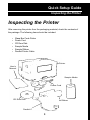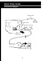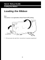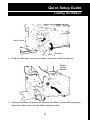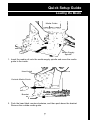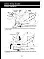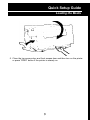
1
W-600 Thermal Label Printer
User’s Guide
for Wasp Bar Code Technologies®
DT/TT Printer
© Copyright Wasp Technologies 2002.
All rights reser ved.
No part of this publication may be reproduced or transmitted in any
form or by any means without the written permission of Wasp
Technologies. The information contained in this document is subject
to change without notice.
Wasp is a trademark of Wasp Technologies. All other trademarks or registered trademarks are the
property of their respective owners.
Table of Contents
Quick Setup Guide
Inspecting the Printer ..............................................................1
Connection Diagram................................................................2
Connecting the Printer ............................................................3
Loading the Ribbon..............................................................4-6
Loading the Media................................................................7-9
Calibrating the Printer............................................................10
Chapter 1
Operator Controls..................................................................11
Chapter 2
Resetting the Printer..............................................................12
Chapter 3
Printer Driver..........................................................................13
Chapter 4
Setting Printer Properties ................................................14-15
Chapter 5
Troubleshooting ................................................................16-18
Chapter 6
Printer Maintenance ..............................................................19
Chapter 7
Technical Specifications ........................................................20
Chapter 8
Product Support & Warranty Information ..............................21
Quick Setup Guide
Inspecting the Printer
Inspecting the Printer
After removing the printer from the packaging material, check the contents of
the package. The following items should be included:
•
•
•
•
•
•
Wasp Bar Code Printer
Power Cord
CD Rom Disk
Sample Media
Sample Ribbon
Parallel Printer Cable
Printer
User’s
Manual
Sample Media
Power Cord
CD Rom Disk
Sample Ribbon
Parallel Cable
1
Quick Setup Guide
Connection Diagram
Parallel Cable
Power Switch
AC Power Connector
Power Jack
AC Electrical Outlet
2
Quick Setup Guide
Connecting the Printer
Power Supply
Note: Before setting up the printer you should consider the following:
1. Find a flat surface with adequate room for the printer. Make sure there is
enough room on the top side for media and ribbon access.
2. The location should be near the PC. consider the distance between PC and
printer for the communication cable (parallel cable).
Parallel Interface Requirements
Note: This printer complies with FCC “Rules and Regulations”, Part 15, for
Class B Equipment, using fully shielded six-foot data cables. Use of longer
cables or unshielded cables may increase radiated emissions above the
Class B limits.
The included cable (IEE 1284-compliant) has a standard 36-pin parallel connector
on one end, which is plugged into the parallel port located on the back of the
printer. The other end of the parallel interface cable connects to the parallel port
on the host computer.
Data cables must be of fully shielded construction and fitted with metal or
metalized connector shells. Shielded cables and connectors are required to
prevent radiation and reception of electrical noise.
To minimize electric noise pickup in the cable:
1. Keep data cables as short as possible (6 feet recommended).
2. Do not tightly bundle the data cables with power cords.
3. Do not tie the data cables to power wire conduits.
3
Quick Setup Guide
Loading the Ribbon
Loading the Ribbon
Note:
This section is not applicable to Direct Thermal (DT) printing.
Top Cover
Front
Access Door
1. Lift top access door and front access door to expose compartment.
4
Quick Setup Guide
Loading the Ribbon
Loading the Ribbon
Head Latch
Bracket
2. Push the head latch counter-clockwise, then push down the bracket.
Ribbon
Supply
Spindle
3. Unwrap the ribbon roll pack and separate the ribbon roll and the empty core.
Insert the ribbon core onto the ribbon supply spindle.
5
Quick Setup Guide
Loading the Ribbon
Print Head Module
Empty Core
4. Attach the edge of the ribbon onto the empty core and wind a few turns.
Lead the empty core through print head module.
Note:
The dull side of the ribbon should face down.
Ribbon Pick-up
Spindle
5. Insert the empty core onto the ribbon pick-up spindle. Turn the pick-up
spindle to insure the ribbon is tightly wound.
6
Quick Setup Guide
Loading the Media
Media Guide
Media Supply
Spindle
1. Insert the media roll onto the media supply spindle and move the media
guide to the inside.
Head Latch
Outside Media Guide
Bracket
2. Push the head latch counter-clockwise, and then push down the bracket.
Remove the outside media guide.
7
Quick Setup Guide
Loading the Media
Print Head
Module
Paper Sensor
Guide
3. Lead the media through the print head module and under the paper
sensor guide.
Head Latch
Bracket
Outside Media Guide
4. Reconnect the outside media guide, close the bracket, and close the
head latch.
8
Quick Setup Guide
Loading the Media
5. Close the top access door and front access door and then turn on the printer
or press “FEED” button if the printer is already on.
9
Quick Setup Guide
Calibrating the Printer
Performing Calibration
Note: This step is very important and must always be carried out whenever
media is being changed. Failure to do so will result in mis-detection of
the label size.
1. Press and hold the “PAUSE” button.
2. Turn on power.
3. When the message “CALIBRATION” is displayed on the LCD, both READY
and MEDIA indicators will blink. At this point, release the button.
4. The printer will then feed 12 inches of label media.
5. When the “READY” message is displayed, the READY and MEDIA indicators
will stop blinking and remain illuminated.
Printing Configuration Report
1. Turn off the printer. Press and hold the FEED button.
2. Turn on the power.
3. When the message “SELF TESTING....” is displayed on the LCD and the
READY indicator blinks, then release the button.
4. The printer will print out a configuration report.
5. When the “READY” message is displayed and the READY indicator stops
blinking and lights up, then the following information will be printed:
• Font list
• DIP switch settings
• Hardware configuration status
• Label parameters
• Firmware version
10
Chapter 1
Operator Controls
Operator Controls
Power Switch - Controls printer power
On - normal operation
Off - the power should be turned off before connecting or
disconnecting the communication cables and
power cables
Feed Button - Advances the media to the printing position
Press - to advance a label
Press - takes the printer out of a “pause” condition
Press and hold while turning on the power to print out the
configuration profile
Pause Button - Stops the printing process
Press - to resume printing process
Press - to perform media calibration
Cancel Button - Terminates the printing process
Press - to force printer to continue after an error
Press - to reset to factory defaults
LED Indicators
Ready - The Ready indicator is illuminated at all times
except:
1.The printer is in a PAUSE state
2. Error condition
Media - The Media indicator will remain on under normal
operating conditions except when blinking = out of media
Ribbon - The Ribbon indicator is illuminated under
thermal transfer mode with ribbon installed except when in
direct thermal mode with no ribbon installed
Blinking = out of ribbon
11
Chapter 2
Resetting the Printer
Resetting the Printer to Factory
Default Settings
1. Turn off the printer. Press and hold the CANCEL button.
2. Turn on the printer.
3. When the message “E2PROM RESET...” is displayed on the LCD and READY
indicator blinks, release the button.
4. When the “Ready” message is displayed, the READY indicator will stop
blinking and light up.
5. The following parameters automatically reset:
• Label parameters
• Heat (Darkness)
• Speed
• Symbol set (language)
• Others for specific emulation
Note:
1. All settings are stored in non-volatile EPROM and cannot be erased when
the printer is turned off.
2. The DIP switch settings cannot be reset.
3. It is necessary to perform a label sensitivity calibration after resetting.
4. The printed label count cannot be reset.
12
Chapter 3
Printer Driver
Printer Driver
The bundled printer driver is compatible with Windows 9x, 2000, ME, XP, and
Windows NT. Through this driver you may print using any Windows software
application that supports Windows printing.
Installing Driver
1. Click the Start, point to Settings, click
Printers, and then double-click Add Printer.
2. Click Network or Local and then click Next.
3. Click Have Disk, click the pull-down menu to select CD ROM (or floppy
disk) drive path.
4. Click Browse.
5. Select the proper operating system for installation:
–WIN9x
–WIN2000
–WINME
–WINXP
–NT4.0
6. The driver name will appear in the “List of Printers,” click Next.
7. Select the communication port for the label printer. For parallel port, select
“LPT1:”, “LPT2:” or “LPT3:”, for serial port, select “COM1:” or “COM2:”.
8. After the related files have been copied to your system, the installation is
complete.
13
Chapter 4
Setting Printer Properties
Setting Printer Properties
After installing the driver, follow the steps below to modify the printer properties:
1. Click Start, point to Settings, and then click Printers.
2. Right-click the icon for the printer you are using and then click Properties.
The properties include:
Ports
Select the IO port you are printing to. This port may be parallel (LPT), serial
(COM), network port or file.
Paper Size
Select your label size from the menu. If your size is not listed, select “Custom” to
define your paper size.
Orientation
Set portrait or landscape according to the print direction.
Paper source (Media type)
T/T stands for Thermal Transfer (ribbon) mode and D/T for Direct Thermal mode
(without ribbon).
14
Chapter 4
Setting Printer Properties (cont.)
Media choice (Darkness)
Some printing applications require changes to the darkness setting.This setting
actually controls the heat intensity of the printhead.The lowest setting is 0;the
highest intensity setting is 15.
Note: In most cases, direct thermal media requires a higher printhead heat than
thermal transfer printing.
Note: Use the lowest intensity setting possible for your application.Printing at the
lowest intensity will reduce the printhead wear.
Copies
This function designates the number of printed copies of each page.
Device options (Speed)
Use the pull down menu to choose the appropriate speed for your printing
application. Speed is measured in inches per second from 1.0 ips to 6.0 ips.
Note: Speed will directly affect print quality: the slower the speed the longer the
media will travel under the print head. For example, direct thermal media is
heat activated; therefore, the label will be more reactive the longer the
print head makes contact with the media.
Note: In most cases, use the slowest speed to achieve the highest print quality.
15
Chapter 5
Troubleshooting
Troubleshooting
Normally, when the printer has an error, the “Ready” LED indicator will blink.
To understand the problem, please check LEDs first:
A. Ready and Media LEDs blink at the same time
Possible
Problems
Solutions
Refer to Pages
Mis-detected
the label gap.
• Check the label path
• Check the label sensor
10-14
Label stock
empty
• Reload labels
10-14
Label stock
not installed
properly
• Reinstall the label roll
10-14
Label jam
• Check media path and
print head for possible
media errors
10-14
16
Chapter 5
Troubleshooting
B. Ready and Ribbon LEDs blink alternately
Possible
Problems
Solutions
Refer to Pages
Ribbon empty
• Reload ribbon
5-9
Ribbon jam
• Reload labels
• Check media and ribbon
5-9
Ribbon sensor
error
• Call tech support
C. Only the Power LED blinks
Possible
Problems
Solutions
Serial IO error
• Check the baud rate
Memory full
• Close all applications
that are not needed
for printing
Hardware error
• Call tech support
17
214-547-4100
Chapter 5
Troubleshooting
D. Miscellaneous
The PC says “Printer Time Out”
1. Make sure the communications cable (parallel or serial) is connected
securely to the parallel or serial port on the PC and the printer.
2. Make sure the printer power is turned on.
If the data has been sent, but here is no output from the printer
Check the active printer driver and make sure the label printer has been
selected.
Vertical streaks in the printout usually indicate a dirty or faulty print head
Example:
Clean the print head first.If the lines still persist, then the print head may need
to be replaced.
Poor print quality
1. Adjust the Darkness (heat temperature)
in the Windows printer driver.
2. Slow down the print speed.
3. Refer to the next chapter and clean
the related spare parts.
18
Chapter 6
Printer Maintenance
Clean the following areas of the printer after 8 rolls of labels have been used. In
each case, use a cotton swab dampened with alcohol. Do not soak the cotton
swab excessively. These supplies can be purchased from Wasp Bar Code
Technologies. Please call 214-547-4100 for details.
Note: Always switch off the power before cleaning.
Cleaning
Thermal Print Head
Thermal paper stock and ribbons will release debris on the print head and
degrade printing quality. Clean the print head with methanol or isopropyl
alcohol with a cotton swab. Do not touch the heater element with your fingers.
Paper Sensor
Debris or dirt on the paper sensor will cause a mis-read or incorrect detection
of the label gap. Clean with a cotton swab dampened with alcohol.
Print Head
Paper Sensor
Guide
19
Chapter 7
Technical Specifications
Model
W-600 Thermal Transfer Printer
Print Method
Direct Thermal or Thermal Transfer
Resolution
203 DPI
Print Width
Up to 4.09”
Maximum Length
45”
Print Speed
6 IPS (Inches Per Second)
Memory
2M of DRAM, 1M Flash ROM Standard
CPU
32 bit RISC Microprocessor
Dimensions
9.8” W x 16” D x 10.2” H
Weight
24.6 lbs
Electrical
FCC Class A/B
110/220 VAC 50/60 Hz
(CE, UL and CUL Approved)
Operating Temperature
40ºF – 100ºF (4ºC – 38ºC)
Storage Temperature
-40ºF – 140ºF (-4ºC – 60ºC)
Humidity
15 – 85% RH
Ribbons
Wax, Wax Resin, and Resin
Labels
Direct Thermal and Thermal Transfer (various)
Label Sensor
Gap and black stripe
20
Chapter 8
Product Support & Warranty Information
Product Support
If you experience any problems with your Wasp W-600 Printer that you are
unable to resolve, call for technical assistance at (214) 547-4100, Monday
through Friday, 8:00 AM - 5:00 PM Central Standard Time. Our web site is
www.waspbarcode.com
You may also contact us in writing at:
Wasp Bar Code Technologies
1400 10th Street
Plano, TX 75074
(214) 547-4100
(214) 547-4101 Fax
Warranty Information
Wasp W-600 Printer is warranted against defects in workmanship and materials
for a period of one year from the date of shipment, provided that the product
remains unmodified and is operated under normal and proper conditions.
Note: W-600 print heads are warranted for 90 days against defect in
workmanship. Print heads will be replaced during the 90 day period
once it is determined that the print head is defective.
This warranty is limited to repair or replacement at Wasp Technologies’ option,
with reasonable promptness after being notified. These provisions do not
prolong the original warranty term for any product which has been repaired or
replaced by Wasp Technologies.
This warranty applies to the original owner and does not extend to any product
which has been subject to misuse, neglect, accidental damage, unauthorized
repair, or tampering.
No other express warranty is given. The replacement or repair of a product is
your exclusive remedy. Any other implied warranty of merchantability or fitness
is limited to the duration of this written warranty. Some states, provinces, and
countries do not allow how long an implied warranty lasts, so the above
limitation may not apply to you.
In no event shall Wasp Technologies be liable for consequential damages. Some
states, provinces, and countries do not allow the exclusion or limitation of incidental
or consequential damages, so the above limitations may not apply to you.
21