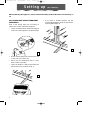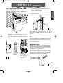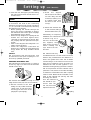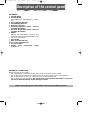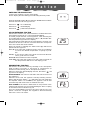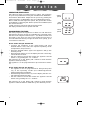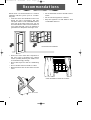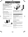
1
FX160/400ECO GB
20-06-2002
16:51
Pagina 21
• This appliance has been manufactured to cool and de-humidify domestic environments and
should not be used for other purposes.
• It is dangerous to alter or modify the unit's characteristics in any way.
• The appliance must be installed in conformity with the relevant national legislation.
• Should repairs be necessary, contact the nearest authorised Repair Service Centre. Unauthorised servicing can be dangerous.
• This appliance is to be used by adults only; keep children away from it.
• Always ground the appliance. Have the electrical system checked by a qualified electrician.
• Avoid using extension leads with the unit.
• Before cleaning or maintenance operations, always unplug the unit from the socket.
• Do not pull on or place strain on the power cable when moving the appliance.
• The appliance should not be installed where the atmosphere may contain combustible gases,
oil or sulphur, or near heat sources.
• If the appliance is utilised in areas where there is no ventilation of air, it is necessary to take precautions to avoid that the refrigerant gases that may leak from the appliance do not remain
in the room, thereby causing a fire hazard.
• This appliance must be utilised and installed only in rooms with a total volume of 15 cubic
metres or greater (31m3 for model FX400ECO).
• Do not rest hot or heavy objects onto the appliance.
• Clean the anti-bacterial filters at least once a week.
• Avoid using heaters near the unit.
• The unit should be transported in a vertical position. If this is not possible secure the unit at an
angle, do not lie horizontally. Before transporting the unit drain the condensation collectingtray and tank. Avoid transportation, wait at least 1 hour before switching on the unit.
• The packaging materials can be recycled. You are therefore recommended to place them in
the special containers for differentiated waste collection.
• Keep the unit at least 50 cm away from inflammable substances (alcohol etc) or pressurised
containers (eg. aerosol cans).
• The appliance must be used only as indicated in this manual. These instructions are not intended to cover as many as possible conditions and situations which may arise. As with all household appliances installation, operation and conservation should be carried out prudently
and following common sense.
• In the case that the power cable becomes damaged, this must be substituted only by specialised personnel authorised by the manufacturer.
• Do not cover this appliance with bags when is not in use.
• R290 is a refrigerant complying with european directives relative to the enviroment. Do not
perforate any component of the refrigerating circuit.
• Unventilated area where the appilance using flammable refrigerants is installed shall be so
constructed that any leaked refrigerants will not stagnate so as to cause a fire or an explosion
hazard caussed by igniting stagnant refrigerants from other source such as electric heater,
stove and similar home applications.
21
ENGLISH
Important Safe-guards
FX160/400ECO GB
20-06-2002
16:51
Pagina 22
How does your pinguino work
D
uring the summer, optimum comfort is achieved with a temperature of between 24 and 27˚C
and about 50% relative humidity.
An air conditioner removes moisture and heat from the room where it is located. One advantage
of portable air conditioning units over fitted models is that they can be moved from one room to
another in the home or even transferred between different buildings.
The hot air in your room is passed through a
coil cooled by refrigerant gas, losing
excess heat and moisture before
being discharged again into the
room.
In single unit models (Pinguino),
a small part of this air is used to
cool the refrigerant gas before, hot and moist air, is being
discharged outside.
In suitcase models (SuperPinguino), the circuit is
cooled using the air outside.
For more details, contact
or visit our Internet site
www.delonghi.com
22
FX160/400ECO GB
20-06-2002
16:51
Pagina 23
Description of the appliance
Description of the Accessories
13)Stopper and flange
14)Air exhaust hose
15)Air exhaust attachment
16)Suckers
17)Wheel locks
DESCRIPTION MODEL FX400ECO
1) External Unit
2) Air discharge grill
3) Control Panel
4) Internal/external unit connection sheath
5) Wheels
6) Handles
7) Rating plate
8) Air intake grill
9) Power cord
10)Stopper for drain tube
11)Water drain tube
ENGLISH
DESCRIPTION MODEL FX160ECO
1) Air discharge grill
2) Control Panel
3) Wheels
4) Handles
5) Housing for air exhaust hose
6) Cord winder
7) Air intake grill
8) Rating plate
9) Water collection tank
10)Water drain tube
11)Stopper for drain tube
12)Power cord
Description of Accessories
1) Wall brackets
2) Support blocks for external unit
3) Belts
4) Eyes
5) Screws and plugs
6) M6 and M4 screws
7) Condensate drain coupling
8) Suckers
9) Wheel locks
10)Wheels for external unit
11)Sheath frame
23
FX160/400ECO GB
20-06-2002
16:51
Pagina 24
Setting up
(Mod. FX160ECO)
When positioning the appliance, always ensure that nothing obstructs the intake and discharge of
air
AIR CONDITIONING WITHOUT PERMANENT
INSTALLATION
Only a few simple steps are necessary to
obtain the comfort offered by Pinguino.
•
• If you have a double window, use the
suckers (16) supplied to keep the panes from
opening wide (figure 3).
Fit the air exhaust hose (14) in its housing (5)
at the rear of the appliance as shown in fig.1
1
2
3
1
• Fit the window discharge attachment (15)
to the end of the hose (14)
• Place the air-conditioning unit at a window or French window
• Open the window a little and position the
attachment (15) as shown in fig. 2.
2
24
20-06-2002
16:51
Pagina 25
Setting up
AIR CONDITIONING WITH SEMI-PERMANENT INSTALLATION
If desired, Pinguino can also be installed on a
semi-permanent basis.
(Mod. FX160ECO)
• Fit the flange (13) supplied to the hole.
• Fix the hose (14) in the housing at the rear
of the appliance (fig 1)
• Fit the end of the hose to the flange (15)
as shown in fig. 5.
MAX115 cm
30 cm
MIN 50 cm
30 cm
5
In this case it will be necessary to:
• Drill a hole in a perimeter wall or in a window pane. Observe the height limits (fig.
5) and the dimensions of the hole given in
fig.4.
When the hose (14) is not connected, the
hole can be closed off with the flange stopper (12).
N.B.
When operating the appliance with semi-permanent installation, it is advisable to leave a
door slightly ajar (even only 1cm), to ensure
free circulation of air.
DEHUMIDIFICATION
Position the appliance in the room without
inserting the air exhaust hose (14); this ensures
that the dehumidified air will be released
directly into the atmosphere.
In the windowpane
4
In the base
of the
window
frame
In the wall: we
advise you to
insulate the section of the wall
with appropriate
insulation
material.
The air emitted through the front grill will be
cold while the air from the rear will be warm
(fig. 6) thus ensuring that the room is dehumidified without variation in temperature.
6
25
ENGLISH
FX160/400ECO GB
FX160/400ECO GB
20-06-2002
16:51
Pagina 26
Setting up
(Mod. FX400ECO)
PREPARING THE INTERNAL UNIT (1)
USING THE QUICK COUPLINGS
Install the appliance inside the room to be air
As an alternative to the methods described
above, the sheath connecting the external
and internal units can be passed through a 6
cm diameter hole in an perimeter wall.
In this case, the external unit couplings must
be disconnected as follows:
conditioned, usually near a window or a perimeter wall.
The internal unit must be positioned level. Use
the wheel blocks (20) supplied. The intake
zone (intake grill (8)) and the discharge zone
(discharge grill (2)) must be kept clear of
obstacles.
NB: Leave at least 30 cm between the wall
and the appliance.
1) Unplug the appliance from the mains supply.
2) Remove the handle by removing the screw
covers and unscrewing the two fixing pins
and the two metric screws; then remove
the front panel.
SHEATH CLIP
POSITIONING THE CONNECTING SHEATH
The sheath connecting the external and internal units can be passed:
a) Through the gap in a window or door left
ajar; use the suckers (20) to prevent opening further (fig. 7).
cm
ELECTRICAL
CONNECTION
BLOCK
PROTECTION
“U”-STAY
9
30
7
3) Remove the “U” stay by unscrewing the
two metric screws (fig 9).
4) Remove the sheath clip (fig 9).
cm
30
b) Through a small hole made in the bottom
of a door or the frame of a window, using
the sheath frame (22) supplied (fig 8).
5) Using a 24 mm spanner, undo the rotating
connection on the coupling. At the same
time, using a 21 mm spanner, hold the end
of the flexible tube (fig10). (repeat for the
second connection using a 24 mm and a
19 mm spanner)
6) Disconnect the condensate tube from the
pipe fitting.
8
cm
26
10
30
20-06-2002
16:51
Pagina 27
Setting up
7) Undo the two self tapping screws holding
the guard and remove the electrical connection block.
(Mod. FX400ECO)
2) Screw
the
support
blocks (13) to the external unit using the M4
screws (17) (taking care
to position them with
the hole for the screw
on top).
AVOID TIGHT CURVES IN THE CONNECTION
SHEATH
Reconnecting the sheath
To reconnect the ends of the connecting
sheath to the internal unit, repeat operations
1, 2, 3, 4, 5, 6 and 7 in reverse order, observing
the following precautions:
• Before passing the sheath through the
hole in the wall, it is advisable to protect
the threaded ends of the quick couplings
with insulating tape or similar.
• Fit the two top refrigerant couplings to the
bottom two and hand tighten them,
checking to ensure that they fit well. Tighten properly with the spanners used previously.
• After connecting the two refrigerant couplings, attach the stays.
• Check the refrigerant connections for
leakage by covering the joints with some
soapy water. No soap bubbles should
form.
3) Attach the external unit
to the brackets, fixing it
with the M6 screws. (17)
13
ENGLISH
FX160/400ECO GB
2
14
1
Alternatively, for temporary
installation, the external unit can be suspended
as shown in fig. 15. In
this case, use the belts
(14) supplied; hook
these to the eyes (15);
before inserting the
eyes, remove the rubber seals.
15
Attention
We recommend that disconnection and
reconnection of the quick couplings be carried out by qualified personnel.
The external unit may
be installed above or at the same level as the
internal unit, provided that the difference in
level is not greater than 1.5m. the air intake
and discharge of the external unit must be
kept clear of obstacles. Leave at least 6 cm
between the wall and the appliance. Condensation forming during operation is eliminated via evaporation from the external unit. In
particular cases, if there is excessive humidity,
to eliminate condensation the drain coupling
must be used. This should be mounted on the
base of the external unit (see fig. 16) after
removing the rubber
Seal
seal. The external
16
unit should be protected from the
sun, rain, snow and
Wheel
drips from the roof.
PREPARING THE EXTERNAL UNIT
The external unit can be placed on a terrace
or balcony. (fig 11). In this case the brackets
should not be used.
11
The external unit can also be hung on a wall
using the brackets (12). Proceed as follows:
1) FFix the bracket to the wall
12
taking care to position it as indicated in fig. 12. (For the holes,
use the jig on the cover of the
polystyrene packaging);
Coupling
27
FX160/400ECO GB
20-06-2002
16:51
Pagina 28
Description of the control panel
THE DISPLAY
A. ON/OFF Button
B. Function Button
Air-conditioning, dehumidifying, ventilation
C. Air-conditioning indicator
D. dehumidifying indicator
E. Purification indicator
F. Increase temperature button / increase
operating time button
G. Decrease temperature button / Decrease
operating time button
H. Display
Displays the temperature selected, time
programmed and (Model FX400ECO only)
the room temperature.
I. Timer button
L. Timer operation indicator
M/N/O/P. Fan speed indicator
Q. Fan speed button
R. Display
room
temperature
button
(FX400ECO)
ELECTRICAL CONNECTION
Before plugging in check that:
• the mains supply corresponds to the value shown in the specifications table;
• the socket and the mains lead correspond to the power requirements of the appliance;
• the socket is suited to the plug, otherwise have the socket replaced;
• the socket is properly grounded. The manufactures cannot be held responsible for any damages due to failure in following normal safety procedures.
Replacement of the power cable must be carried out by qualified personnel.
28
FX160/400ECO GB
20-06-2002
16:51
Pagina 29
O p e r a t i o n
SWITCHING THE APPLIANCE ON
ENGLISH
Connect the appliance to the mains supply.
On the display two lines will appear indicating Stand-by mode
Press the ON/OFF button (A) and then the MODE button until the
relevant function indicator appears viz.:
Indicator C
: air-conditioning
Indicator D
: dehumidifying
Indicator E
: purification/ventilation
AIR-CONDITIONING FUNCTION
This function is ideal in hot, humid weather conditions when the
atmosphere requires to be cooled and dehumidified.
To ensure proper function of the appliance, after selecting the
air-conditioning function, press buttons + (F) or – (G) until the desired temperature appears on the display.
The temperatures most suited to the atmosphere in summer vary
between 24 and 27°C. We do not advise selection of temperatures much lower than those outside.
Select fan speed by pressing the “FAN” button (Q) until the fan
speed indicator appears:
MAX (P): if you want the maximum power of the air-conditioner
to reach the desired temperature as quickly as possible.
MIN (O): if you want to reduce the level of noise and still maintain a good level of comfort.
SILENT (N): when minimum noise is required,
AUTO (M):if you prefer the appliance to select the fan speed for
the temperature selected on the display panel.
25
DEHUMIDIFYING FUNCTION
This function is ideal for reducing humidity in the atmosphere
while avoiding increases or decreases in temperature (in
between seasons, damp places, wet spells of weather).
When you select the dehumidifying function, the letters “ ” will
appear on the display.
Model FX160ECO: the water is collected in the tank at the rear of
the appliance.
When the tank is full, the appliance will stop working and the
display will show the letters “
” (Full Tank); the tank must then
be emptied. When it is re-inserted, the appliance will re-start
automatically. N.B. remove the air exhaust hose (13).
Mod. FX400ECO: the water is eliminated via evaporation in the
external unit. However, we recommend fitting the drain coupling
to the external unit as shown in fig. 16
Once the dehumidifying function has been selected, the fan
speed cannot be changed. The appliance will automatically
select the correct fan mode.
29
FX160/400ECO GB
20-06-2002
16:51
Pagina 30
O p e r a t i o n
VENTILATION/PURIFICATION
This is ideal for dusty or polluted areas; in effect, the appliance
recycles and purifies the air using the dust filters and 3M Filtrete™
electrostatic filters fitted. Adjust the fan speed by pressing the
“FAN” (Q) button, as illustrated in the air conditioning function.
Bear in mind that the higher the speed, the greater the volume
of air filtered; by selecting the “Silent” speed, less air is filtered, but
the noise level is low.
“AUTO” function cannot be selected in this mode.
The display will show the fan speed selected.
PROGRAMMING THE TIMER
“Silent”
speed
“Min”
speed
“Max”
speed
The timer programs the appliance to switch on and switch off.
This will save electrical energy by optimizing the operating times.
The timer is set using the buttons + (F) or – (G); these increase and
decrease by one hour at a time, but if pressed for more than 2
seconds will automatically change the time more quickly, up to
a maximum of 24 hours.
How to set the delayed start function
• Connect the appliance to the mains supply and press
ON/OFF button: next, select the required operating mode
(temperature, fan speed etc.)
• Press the ON/OFF button again: the appliance will go into
stand-by mode.
• Press the timer button (1): on the display the two central segments will start to flash.
• Set the number of hours after which the appliance should
switch on, by pressing the + or – buttons.
The indicator (L) on the display will continue to flash until the
appliance starts operating.
The appliance can be programmed for up to 24 hours in advance.
How to set the delayed stop function
• The appliance can be programmed for delayed stop from
any of the operating modes (air-conditioning/dehumidifying/purification/ventilation.
• Press the Programmer button (1): on the display the two central segments will start to flash.
• Set the number of hours after which the appliance should
switch off by pressing the + or – buttons.
The indicator (L) on the display will continue to flash until the
appliance switches itself off. It will then go into Stand-by mode.
30
25
FX160/400ECO GB
20-06-2002
16:51
Pagina 31
O p e r a t i o n
When pressing this button (R), the room temperature is shown on the display for a few seconds. It
then reverts to showing the current mode. The room temperature cannot be displayed while in
Stand-by mode.
SELF-DIAGNOSIS
The appliance is equipped with a self-diagnosis system which identifies any operating problems.
IF THE DISPLAY SHOWS…
….WHAT SHOULD YOU DO?
H P HIGH PRESSURE
Insert and re-insert the plug. If the problem persists, call the service
centre.
LOW TEMPERATURE
If the machine is operating as an air-conditioner or dehumidifier, this
will prevent the formation of ice. The appliance will start up automatically once the defrosting process has ended.
F F FAN FAILURE
If either of these messages appears, call the service centre.
P F PROBE FAILURE
FULL TANK
FX160ECO
Empty the tank at the rear of the appliance and reposition correctly.
FX400ECO
Empty the internal tank (not visible) through the small drain tube
(11); replace the rubber stopper.
31
ENGLISH
ROOM TEMPERATURE BUTTON (MODEL FX400ECO)
FX160/400ECO GB
20-06-2002
16:51
Pagina 32
Recommendations
Follow these recommendations to achieve
maximum efficiency from your air conditioning unit:
• Close the doors and windows in the room
where the unit is functioning. The only
exception is in the case of installation through a hole in the wall. In this case, you are
recommended to allow a small amount of
air to enter through a door or window to
guarantee an adequate exchange of air.
• Do not install the heater in humid environments.
• Do not use the appliance outdoors.
• Keep the appliance a safe distance from
combustible surfaces
close doors and windows
• Protect the room from direct exposure to
the sun’s rays by drawing the curtains
and/or partially lowering the blinds so as
to maximise energy savings.
• Do not rest objects on the air conditioning
unit.
• Do not obstruct the air intake or outlet.
• Make sure there are no heat sources in the
room.
lower the blinds or draw the curtains
do not cover
32
FX160/400ECO GB
20-06-2002
16:51
Pagina 33
Cleaning
Before cleaning or maintenance, switch off the
appliance by pressing the ON/OFF button (A)
and always unplug it from the mains supply.
Precautions
Never clean with benzene, alcohol or solvents. Never spray with liquid insecticide or
similar.
CLEANING THE AIR FILTERS
To maintain the air-conditioning unit at peak
efficiency, we advise you to:
1. Clean the dust filter weekly.
2. Replace the air filters at the end of each
season or when necessary (follow the
instructions on the appliance near the filter).
The filters are located behind the two intake
grills. The grills contain the filters.
To clean the filters:
1. Remove the intake grills by rotating them
outwards. (fig 17)
2. Remove the 3M purification filter (white).
Dust filter
intake grille
Purification filter 3M
18
bacterial filter, use a vacuum cleaner. If very
dirty, immerse in warm water (not more than
40° C) and rinse thoroughly.
Allow the filter to dry. To replace, fit the filters
to the intake grill and attach to the appliance.
Do not try to clean the 3M filter as this could
result in a reduction of filter capacity.
BEGIN OF SEASON CHECKS
Check that the power cord and plug are
undamaged and that the appliance is properly earthed.
The installation instructions should be observed
meticulously.
END OF SEASON OPERATIONS
Empty the water from the tank.
2
1
17
3. Remove the dust filter by detaching it from
the external grill.
To remove the dust deposited on the anti-
Mod. FX160ECO:
Remove the tank (9) and empty it. To drain
any residual water from the internal circuit,
remove the stopper (11) from the drain tube
(10) and drain completely. Re-insert the stopper and re-position the tank correctly(9).
Mod. FX400ECO:
Empty the internal tank (not visible) through
the small drain tube (10); replace the rubber
stopper (11).
Clean the anti-bacteria filters and dry well
before replacing.
33
ENGLISH
CLEANING THE EXTERNAL UNIT
We recommend cleaning the appliance with
a slightly damp cloth. It should then be dried.
For safety reasons, do not wash the air-conditioner with water.
FX160/400ECO GB
20-06-2002
16:51
Pagina 34
Troubleshooting
PROBLEM
CAUSES
REMEDY
The air-conditioner
does not work
•
•
the power is off
the appliance is not plugged in
•
Plug it in
(Mod. FX160ECO).
The air-conditioner
works only for a
short time
•
•
The exhaust hose is twisted
The exhaust hose is blocked
•
•
•
The exhaust hose is bent
•
Position exhaust hose correctly
Check for obstacles blocking
the exhaust system
Straighten the hose
The air-conditioner
works but does not
cool the room.
•
•
a window is open
there is a source of heat in the room (lamp,
burner etc.) or there are many people in the
room.
the thermostat is set too high
•
•
close the window
eliminate source of heat
•
air filters are dirty
the capacity of the air-conditioner is not
adequate for the conditions or the dimensions of the room.
•
set the thermostat to a lower
temperature
clean/replace filters
Strange odour in the •
room
air filters are dirty
•
clean/replace filters
Leaking condensate from the unit
•
appliance incorrectly installed
•
•
condensate collection tank is full
•
see instructions for correct
installation of appliance
Mod. FX160ECO: empty the
tank
Mod. FX400ECO: drain the
water through the drain tube
found at the rear of the
appliance.
•
The safety mechanism has been activated
•
•
•
•
The unit does not work
for about 3 minutes
after turning on the
appliance.
wait for 3 minutes
See paragraph “Self diagnosis” if the following messages appear on the display: FF, HP, LT, FT, PF.
34
FX160/400ECO GB
20-06-2002
16:51
Pagina 35
Technical specification
TECHNICAL SPECIFICATION
Room temperature
21 - 35°C
FX400 ECO
OPERATING LIMITS
Room temperature
21 ÷ 32°C
Outside temperature
21 ÷ 43°C
Power supply
Max. absorbed power
in air conditioning
Max. absorbed power
when dehumidifying
see rating plate
“
“
Refrigerating capacity*
“
Number of fan speeds
2 + silent
Max. air flow
460 m3/h
Dimensions of internal unit:
• width
• height
• depth
• weight
452 mm
800 mm
455 mm
33 kg
Dimensions of external unit (only FX400 eco):
• width
570 mm
• height
480 mm
• depth
260 mm
• weight
18 kg
*
Standard conditions:
Room temperature
27°C
47% relative humidity
Outside temperature
35°C
41% relative humidity
ELECTRICAL CONNECTION (U.K. ONLY)
A) If your appliance comes fitted with a plug, it will incorporate a 13 Amp fuse. If it does not fit your socket, the plug should
be cut off from the mains lead, and on appropriate plug fitted, as below. warning: Very carefully dispose of the cut off
plug after removing the fuse: do not insert in a 13 Amp socket elsewhere in the house as this could cause a shock hazard.
With alternative plugs not incorporating a fuse, the circuit must be protected by a 15 Amp fuse. If the plug is a mouldedon type, the fuse cover must be re-fitted when changing the fuse using a 13 Amp Asta approved fuse to BS 1362. In the
event of losing the fuse cover, the plug must NOT be used until a replacement fuse cover can be obtained from your nearest electrical dealer. The colour of the correct replacement fuse cover is that as marked on the base of the plug.
B) If your appliance is not fitted with a plug, please follow the instructins provided below:
WARNING - THIS APPLIANCE MUST BE EARTHED
IMPORTANT
The wires in the mains lead are coloured in accordance with
the following code:
Green and yellow Earth
Blue
Neutral
Brown
Live
E
L
N
As the colours of the wires in the mains lead may not correspond with the coloured markings identifying the terminals
in your plug, proceed as follows:
The green and yellow wire must be connected to the terminal in the plug marked with the letter E or the earth symbol
or coloured green or green and yellow.
The blue wire must be connected to the terminal marked with
the letter N or coloured black.
The brown wire must be connected to the terminal marked
with the letter L or coloured red.
35
ENGLISH
FX160 ECO
OPERATING LIMITS