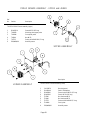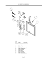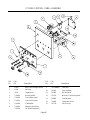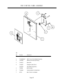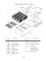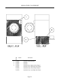
1
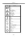
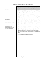
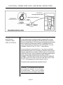
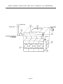
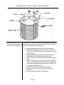
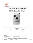
OWNER'S MANUAL
170 lb. HD LAUNDRY DRYER
Gas: Natural and LP
Steam
Technical specifications
Installation instructions
Operating instructions
Maintenance
HD170
Cissell Manufacturing Co.
831 S. First St. - P.O.Box 32270 - Louisville, Ky. - 40232-2270
Tel: (502) 587-1292 - Fax: (502) 585-2333
Sales Fax: (502) 585-3625 - Service/Parts Fax: (502) 681-1275
Page 1
THIS MANUAL MUST BE GIVEN TO THE EQUIPMENT OWNER
MANHD170
3/06
IMPORTANT NOTICES—PLEASE READ
For optimum efficiency and safety, we recommend that you read the Manual before operating the equipment. Store this manual in a file
or binder and keep for future reference.
WARNING: For your safety, the information in this manual must be followed
to minimize the risk of fire or explosion or to prevent property damage,
personal injury, or loss of life.
- Do not store or use gasoline or other flammable liquids or vapors in the
vicinity of this or any other appliance.
- WHAT TO DO IF YOU SMELL GAS
•
•
•
•
•
Do not try to light any appliances.
Do not touch any electrical switch; do not use any phone in your building.
Clear the room, building, or area of all occupants.
Immediately call your gas supplier from a neighbor's phone. Follow the
gas supplier's instructions.
If you cannot reach the gas supplier, call the fire department.
Installation and service must be performed by a qualified installer, service
agency or the gas supplier.
WARNING: In the event the user smells gas odor, instructions on what to do must be
posted in a prominent location. This information can be obtained from the local gas
supplier.
WARNING:
Wear Safety Shoes to prevent injuries.
WARNING:
Purchaser must post the following notice in a prominent location:
FOR YOUR SAFETY
Do not store or use gasoline or other flammable vapors
and liquids in the vicinity of this or any other appliance.
WARNING: A clothes dryer produces combustible lint and should be exhausted outside the
building. The dryer and the area around the dryer should be kept free of lint.
WARNING: Be safe, before servicing machine, the main power should be shut off.
Page 2
IMPORTANT NOTICES—PLEASE READ
WARNING: To avoid fire hazard, do not dry articles containing foam rubber or similar texture
materials. Do not put into this dryer flammable items such as baby bed mattresses, throw rugs,
undergarments (brassieres, etc.) and other items which use rubber as padding or backing. Rubber easily
oxidizes causing excessive heat and possible fire. These items should be air dried.
WARNING: Synthetic solvent fumes from drycleaning machines create acids when drawn through the
dryer. These fumes cause rusting of painted parts, pitting of bright or plated parts, and completely
removes the zinc from galvanized parts, such as the tumbler basket. If drycleaning machines are in the
same area as the tumbler, the tumbler's make-up air must come from a source free of solvent fumes.
WARNING: Do not operate without guards in place.
WARNING: Check the lint trap often and clean as needed but at least a minimum of once per day.
WARNING: Alterations to equipment may not be carried out without consulting with the factory and
only by a qualified engineer or technician. Only Manufacturer’s parts may be used.
WARNING: Remove clothes from dryer as soon as it stops. This keeps wrinkles from setting in and
reduces the possibility of spontaneous combustion.
WARNING: Be Safe - shut main electrical power and gas supply off externally before attempting
service.
WARNING: Never use drycleaning solvents, gasoline, kerosene, or other flammable liquids in the dryer.
FIRE AND EXPLOSION WILL OCCUR. NEVER PUT FABRICS TREATED WITH THESE
LIQUIDS INTO THE DRYER. NEVER USE THESE LIQUIDS NEAR THE DRYER..
WARNING: Do not place items exposed to cooking oils in your dryer. Items contaminated
with cooking oils may contribute to a chemical reaction that could cause a load to catch fire.
WARNING: Never let children play near or operate the dryer. Serious injury could occur if a child
should crawl inside and the dryer is turned on.
WARNING: Never tumble fiberglass materials in the dryer unless the labels say they are machine
dryable. Glass fibers break and can remain in the dryer. These fibers cause skin irritation if they
become mixed with other fabrics.
WARNING: Before operating gas ignition system - purge air from natural gas or propane gas lines
per manufacturer’s instructions.
WARNING: To reduce the risk of electric shock, disconnect this appliance from the power supply
before attempting any user maintenance other than cleaning the lint trap. Turning the controls to the
OFF position does not disconnect this appliance from the power supply.
Page 3
IMPORTANT NOTICES—PLEASE READ
ATTENTION: L’ACHETEUR DOIT PLACER L’AVERTISSEMENT
SUIVANT DANS UN ENDROIT CLAIR ET VISIBLE:
AVERTISSEMENT. Assurez-vous de bien
suivre les instructions donnees dans cette
notice pour reduire au minimum le risque
d’incendie ou d’explosion ou pour eviter tuot
dommage materiel, toute blessure ou la mort.
__ Ne pas entreposer ni utiliser d’essence ni
d’autres vapeurs ou liquides inflammables dans
le voisinage de cet appareil ou de tout autre
apparell.
__ QUE FAIRE SI VOUS SENTEZ UNE
ODEUR DE GAZ:
• Ne pas tenter d’allumer d’apparell.
• Ne touchez a aucun interrupteur. Ne pas
vous servir des telephones se trouvant dans
le batiment ou vous vous trouvez.
• Evacuez la piece, le batiment ou la zone.
• Appelez immediatement votre fournisseur de
gaz depuis un voisin. Suivez les instructions
du fournisseur.
• Si vous ne pouvez rejoindre le fournisseur
de gaz, appelez le service des incendies.
__ l’installation et l’entretien doivent etre assures
par un installateur ou un service d’entretien
qualifie ou par le fournisseur de gaz.
ATTENTION: L’ACHETEUR DOIT PLACER L’AVERTISSEMENT
SUIVANT DANS UN ENDROIT CLAIR ET VISIBLE:
POUR VOTRE SECURITE
Ne pas entreposer ni utiliser d’ essence
ni d’autres vapeurs ou liquides
inflammables dans le voisinage de cet
appareil ou de tout autre appareil.
Page 4
CISSELL WARRANTY
The Cissell Manufacturing Company (Cissell) warrants all new equipment (and the original parts thereof) to be free from defects
in material or workmanship for a period of three (3) years from the date of sale thereof to an original purchaser for use, except
as hereinafter provided. With respect to non-durable parts normally requiring replacement in less than three (3) years due to
normal wear and tear, and with respect to all new repair or replacement parts for Cissell equipment for which the three (3) year
warranty period has expired, or for all new repair or replacement parts for equipment other than Cissell equipment, the warranty
period is limited to ninety (90) days from date of sale. The warranty period on each new replacement part furnished by Cissell
in fulfillment of the warranty on new equipment or parts shall be for the unexpired portion of the original warranty period on
the part replaced.
With respect to electric motors, coin meters and other accessories furnished with the new equipment, but
not manufactured by Cissell, the warranty is limited to that provided by the respective manufacturer.
Cissell's total liability arising out of the manufacture and sale of new equipment and parts, whether under
the warranty or caused by Cissell's negligence or otherwise, shall be limited to Cissell repairing or replacing,
at its option, any defective equipment or part returned f.o.b. Cissell's factory, transportation prepaid, within
the applicable warranty period and found by Cissell to have been defective, and in no event shall Cissell be
liable for damages of any kind, whether for any injury to persons or property or for any special or
consequential damages. The liability of Cissell does not include furnishing (or paying for) any labor such
as that required to service, remove or install; to diagnose troubles; to adjust, remove or replace defective
equipment or a part; nor does it include any responsibility for transportation expense which is involved
therein.
The warranty of Cissell is contingent upon installation and use of its equipment under normal operating
conditions. The warranty is void on equipment or parts; that have been subjected to misuse, accident, or
negligent damage; operated under loads, pressures, speeds, electrical connections, plumbing, or conditions
other than those specified by Cissell; operated or repaired with other than genuine Cissell replacement
parts; damaged by fire, flood, vandalism, or such other causes beyond the control of Cissell; altered or
repaired in any way that effects the reliability or detracts from its performance, or; which have had the
identification plate, or serial number, altered, defaced, or removed.
No defective equipment or part may be returned to Cissell for repair or replacement without prior written
authorization from Cissell. Charges for unauthorized repairs will not be accepted or paid by Cissell.
CISSELL MAKES NO OTHER EXPRESS OR IMPLIED WARRANTY, STATUTORY OR OTHERWISE,
CONCERNING THE EQUIPMENT OR PARTS INCLUDING, WITHOUT LIMITATION, A WARRANTY
OF FITNESS FOR A PARTICULAR PURPOSE, OR A WARRANTY OF MERCHANTABILITY. THE
WARRANTIES GIVEN ABOVE ARE EXPRESSLY IN LIEU OF ALL OTHER WARRANTIES, EXPRESS
OR IMPLIED. CISSELL NEITHER ASSUMES, NOR AUTHORIZES ANY PERSON TO ASSUME FOR IT,
ANY OTHER WARRANTY OR LIABILITY IN CONNECTION WITH THE MANUFACTURE, USE OR SALE
OF ITS EQUIPMENT OR PARTS.
For warranty service, contact the Distributor from whom the Cissell equipment or part was purchased. If
the Distributor cannot be reached, contact Cissell.
IDENTIFICATION
NAMEPLATE
The Identification Nameplate is located on the rear wall of the dryer. It contains the dryer serial number, product
number, model number, electrical specifications and other important data that may be needed when servicing
and ordering parts, wiring diagrams, etc. Do not remove this nameplate.
Page 5
TABLE OF CONTENTS
PAGE
Model Numbers & Company Address .................................................................................. 1
Important Notices .............................................................................................................. 2-4
Dryer Warranty .................................................................................................................... 5
Table of Contents .............................................................................................................. 6-7
Warnings, Symbols ........................................................................................................... 8-9
Unpacking/General Installation ....................................................................................... 10-11
General Dimensions ....................................................................................................... 12-13
Dryer Specifications ....................................................................................................... 14-15
Electrical Connections ......................................................................................................... 16
Gas Piping ..................................................................................................................... 17-18
Gas Pipe Size Chart ............................................................................................................ 19
Gas Piping Installation ......................................................................................................... 20
Bonnet Shipped Separately - Installation Instructions ...................................................... 21-22
Steam Piping Installation ................................................................................................ 23-24
Exhaust Installation - Multiple Exhaust ............................................................................ 25-27
Dryer Make-up Air Requirements ....................................................................................... 28
Exhaust Installation - Separate Exhaust ................................................................................ 29
Dryer Air Flow Installation .................................................................................................. 30
Rules for Safe Operation of Dryer ....................................................................................... 31
Energy Saving Tips ............................................................................................................. 32
Operating Instructions -Two Timer Models .................................................................... 33-35
Service Savers .................................................................................................................... 36
Troubleshooting Charts .................................................................................................. 37-39
Direct-Spark Ignition Operation ..................................................................................... 40-41
General Maintenance .......................................................................................................... 42
Burner Air Inlet Adjustment ................................................................................................ 43
Basket Alignment (TM200 Gear Reducer) ..................................................................... 44-45
Basket Alignment (Gear Motor) .......................................................................................... 46
Shimming the Basket and Spider Assembly ......................................................................... 47
Air Switch Adjustment ........................................................................................................ 48
Dryers with Reversing Control Timer .............................................................................. 49-50
Large Gear Reducer Maintenance ....................................................................................... 51
Front Exploded View ......................................................................................................... 52
Rear View (TM200 Gear Reducer) ............................................................................... 53-54
Rear View (Gear Motor) ...............................................................................................55-56
Front Panel and Door Assembly ......................................................................................... 57
Two Timer Thermostat Assembly ........................................................................................ 58
Burner Access Door ........................................................................................................... 59
Lint Door Assembly ............................................................................................................ 60
DMP Sensor Assembly ...................................................................................................... 61
Two Timer Sensor Assembly .............................................................................................. 62
Pro Sensor Assembly ......................................................................................................... 63
ProHc Sensor Assembly ..................................................................................................... 64
Page 6
TABLE OF CONTENTS
Air Switch Assembly .......................................................................................................... 65
Two Timer Control Panel Assembly .................................................................................... 66
DMP Control Panel Assembly ............................................................................................ 67
Pro Control Panel Assembly ............................................................................................... 68
ProHC Control Panel Assembly .......................................................................................... 69
Rear Motor Control Assembly ............................................................................................ 70
Parts - TM200 Gear Reducer ............................................................................................. 71
Gas Bonnet Assembly ......................................................................................................... 72
Steam Bonnet Assembly - TU14027 ................................................................................... 73
Insulation and Covers ......................................................................................................... 74
Page 7
SYMBOLS
The following symbols are used in this manual and/or on the machine.
Symbol
Description
NOTE!
Hot! Do Not Touch
Heiß! Nicht Beruhren
Haute temperature! Ne pas
toucher
Caliente! no tocar
dangerous voltage
tension dangereuse
Gefährliche elektrische
Spannung
tension peligrosa
on
marche
Ein
conectado
off
arrêt
Aus
desconectado
start
demarrage
Start
arranque de un movimiento
emission of heat in general
êmission de chaleur en
general
Warmeabgabe allgemein
emisión de calor
cooling
refroidissement
Kühlen
enfriamiento
Page 8
SYMBOLS
Symbol
Description
rotation in two directions
rotation dans les deux sens
Drehbewigung in zwei Richtungen
movimiento rotativo en los dos
sentidos
direction of rotation
sens de mouvement continu de rotation
Drehbewegung in Pfeilrichtung
movimiento giratorio o rotatorio
en el sentido de la flecha
End of Cycle
caution
attention
Achtung
atencion; precaucion
Page 9
UNPACKING/GENERAL INSTALLATION (ALL DRYERS)
UNPACKING
This dryer is packed in a large wooden crate.
Upon arrival of the equipment, any damage in shipment should
be reported to the carrier immediately.
Upon locating permanent location of a unit, care should be taken
in movement and placement of equipment.
See outline clearance diagrams for correct dimensions.
Remove all packing material such as: tape, manuals, skid, etc.
Leveling: Use spirit level on top of dryer. The use of shims are acceptable
for this procedure.
GENERAL
INSTALLATION
(ALL DRYERS)
Check voltage and amperes on rating plate before installing the
dryer.
The construction of the dryers permits installation side-by-side
to save space or to provide a wall arrangement. Position dryer
for the least amount of exhaust piping and elbows, and allow
free access to the rear of dryer for future servicing of belts,
pulleys and motors. Installation clearance from all combustable
material is 0” ceiling clearance, 0” rear clearance, and 0” side
clearance.
IMPORTANT
Opening the clothes loading door deactivates the
door switch to shut off the motors, fan, gas, steam, or
electric element. To restart the dryer, close the door
and press in the push to start button and hold briefly.
IMPORTANT
This dryer is designed for a capacity maximum load.
Overloading it will result in long drying times and
damp spots on some clothes.
IMPORTANT
Maximum operating efficiency is dependent upon
proper air curculation. The lint screen must be kept
cleaned daily to insure proper air circulation
throughout the dryer.
Page 10
GENERAL INSTALLATION (ALL DRYERS)
IMPORTANT
Provide adequate clearance for air openings into the
combustion chamber.
GENERAL
Replacement parts for this dryer are available from your distributor
or by contacting the factory at the address or phone number printed
on the cover of this manual.
1 . Unscrew two (2) front cover panel hold-down screws and
open the front cover panel. If wires enclosed are not color
coded or numbered, mark wires before disconnecting. Refer
to the wiring diagram.
IMPORTANT
REPLACEMENT PARTS
PROCEDURE FOR
DISASSEMBLING THE
TOP OF THE DRYER
2 . Disconnect the wire plugs in the right and left control boxes.
Unscrew the two (2) hold-down bolts from the bottom of the
boxes and one screw from the outside rear of the boxes.
Remove the two (2) screws that hold the conduit plate to the
boxes. Remove the boxes and the top brace as one assembly.
3 . Unscrew the six (6) bolts that hold down the heating unit.
4 . Remove the air switch box on the rear of the dryer and
disconnect the two (2) wires and the box from the rear of
the dryer. Leave the air switch fastened to the dryer rear
wall.
5 . To re-assemble, reverse this procedure.
Page 11
GAS DRYER DIMENSIONS
Page 12
STEAM DRYER DIMENSIONS
Page 13
DRYER SPECIFICATIONS
GENERAL
SPECIFICATIONS
FOR 150 lb. DRYERS
Floor Space ............................................ 64” (1626 mm) Deep x 54”
(1372 mm) Wide x 96”
(2439 mm) High
Doors .................................................... 31-1/4” (794 mm) Diameter
Basket Size .......................................... 50” (1270 mm) Diameter x
42” (1067 mm) Deep
Basket Capacity (Dry Weight) ........ 150 lbs. (68.0 kg) Dryweight
Basket Motor ...................................... 1-1/2 HP (1.12 kW)
Fan Motor ............................................ 1-1/2 HP (1.12 kW)
Basket RPM (Reversing) ................. 28 - 3.2 reversals per min.
(Non-Reversing) ................................. 3 0
Exhaust Duct ..................................... 12” (305 mm) Diameter
Maximum Air Displacement ........... 2,250 cfm (3825 m 3/h)
Recommended Operating ................ 1,900 - 2,100 cfm
Range
(3230 - 3570 m3/h)
Net Weight (Gas) ............................... 1,740 lbs. (789 kg) approx.
(Steam) ................................................. 1,754 lbs. (796 kg) approx.
Shipping Weight (Gas) ..................... 1,890 lbs. (857 kg) approx.
(Steam) ................................................. 1,944 lbs. (882 kg) approx.
Export Shipping Dimensions .......... 104” H (2642 mm) x 60” W
(1524 mm) x 74” L (1880 mm)
Export Crate (Gas) ............................ 254.5 ft³ (7.21 m³)
(Steam) ................................................. 261.1 ft³ (7.40 m³)
Load Weight on Floor Area ............. .69 lb./sq. in. (48.5 lb./sq. in.)
BTU Input Rating *
(see next page) ...............
370,000 Btu per hour
(93,240 kcal/h)
(Nat., Mixed, Mfg., Butane and
Propane Gases)
Steam Consumption ......................... 12.5 bhp - 419 lbs.
(418,187 Btu/h)
Operating Steam Pressure .............. 100 psi (6.9 bar) max
Gas Supply .......................................... 1” (3 mm) Pipe Connection
Manifold Pressure ............................. 3.5”w.c. (8.7 mbar) (Natural Gas)
11”w.c. (27 mbar) (LP Gas)
Electric Ignition ................................. Direct Spark Ignition System
Page 14
DRYER SPECIFICATIONS
STEAM HEATED DRYERS ONLY
Operating Steam Pressure
100 psig (6.9 bar) Maximum
Boiler HP
12.5 HP (9.33 kW)
Heat Capacity
8 Coil
Steam Coils
(4) 6”(153 mm) x 10 1/4” (261 mm)
x 40 1/2”(1029 mm)
Steam Supply Connection
3/4” (20 mm)
Steam Return Connection
3/4” (20 mm)
Trap Connection
(2) 3/4” (20 mm)
Maximum Air Displacement
2250 cfm (63.7 m³/h)
Page 15
ELECTRICAL CONNECTIONS (WITH GROUNDING INSTRUCTIONS
ELECTRICAL
CONNECTIONS
FOR ALL DRYERS
Dryers must be electrically grounded by a separate #14 or larger
green wire from the grounding terminal within the service connection
box, to a cold water pipe. In all cases, the grounding method must comply
with local electrical code requirements; or in the absence of local
codes, with the National Electrical Code, ANSI/NFPA 70 or the
Canadian Electrical Code, CA C22.1—Latest Edition.
See wiring diagram furnished with dryer. Your dryer is completely
wired at the factory and it is only necessary for the electrician to connect
the power leads to the wire connectors within the service connection box
on the rear of the dryer. Do not change wiring without consulting the
factory, as you may void the factory warranty. DO NOT
CONNECT THE DRYER TO ANY VOLTAGE OR CURRENT
OTHER THAN THAT SPECIFIED ON THE DRYER RATING
PLATE. (Wiring diagram is located on rear wall of dryer.)
All panels must be in position before operation of dryer.
«Attention. Lors des opérations d’entretien
des commandes, ètiqueter tous les fils avant
de les dèconnecter. Toute erreur de câblage
peut être une source de danger et de panne»
Page 16
GAS PIPING
GAS SERVICE
INSTALLATION
INFORMATION
The size of the gas service pipe is dependant upon many variables, such
as tees, lengths, etc. Specific pipe size should be obtained from the gas
supplier. Refer to the Gas Pipe Size Chart in this manual for general gas
pipe size information.
CAUTION
Gas loop piping must be installed as shown in Illustration, to
maintain equal gas pressure for all dryers connected to a
single gas service.
Other gas using appliances should be connected upstream
from the loop.
WARNING
(LIQUIFIED PETROLEUM GASES ONLY)
A Gas Pressure Regulator for Liquified Petroleum Gases is
not furnished on Gas Heated Clothes Dryers. This regulator
is normally furnished by the installer. In accordance with
American Gas Association (AGA) standards, a gas pressure
regulator, when installed indoors, must be equipped with a
vent limiter, or a vent line must be installed from the gas
pressure regulator vent to the outdoors.
Page 17
GAS PIPING INSTALLATION (ILLUSTRATION)
Page 18
GAS PIPE SIZE CHART
TOTAL BTU/HR
(for LP Gas correct
total Btu/h below by
multiplying by .6)
TOTAL
KCAL
HOUR
GAS PIPE SIZE FOR 1000 Btu (252 kcal/h) NATURAL GAS
AT 7” w. c. (17.5 bar) PRESSURE
In figuring total length of pipe, make allowance for tees and elbows.
(25 ft.)
(50 ft.)
(75 ft.)
(100 ft.)
(125 ft.)
(150 ft.)
7,62 m
15,24 m
22,86 m
30,48 m
38,1 m
45,72 m
60,000
15000
3/4
3/4
3/4
3/4
3/4
3/4
80,000
20000
3/4
3/4
3/4
1
1
1
100,000
25200
3/4
3/4
1
1
1
1
120,000
30200
3/4
1
1
1
1
1
140,000
35200
3/4
1
1
1
1
1 1/4
160,000
40300
3/4
1
1
1 1/4
1 1/4
1 1/4
180,000
45300
1
1
1
1 1/4
1 1/4
1 1/4
200,000
50400
1
1
1 1/4
1 1/4
1 1/4
1 1/2
300,000
75600
1
1 1/4
1 1/4
1 1/2
1 1/2
1 1/2
400,000
100800
1 1/4
1 1/4
1 1/2
1 1/2
1 1/2
2
500,000
126000
1 1/4
1 1/2
1 1/2
2
2
2
600,000
151200
1 1/2
1 1/2
2
2
2
2
700,000
176400
1 1/2
2
2
2
2
2 1/2
800,000
202000
1 1/2
2
2
2
2 1/2
2 1/2
900,000
230000
2
2
2
2 1/2
2 1/2
2 1/2
1,000,000
250000
2
2
2
2 1/2
2 1/2
2 1/2
1,100,000
270000
2
2
2 1/2
2 1/2
2 1/2
2 1/2
1,200,000
300000
2
2
2 1/2
2 1/2
2 1/2
2 1/2
1,300,000
330000
2
2 1/2
2 1/2
2 1/2
2 1/2
3
1,400,000
350000
2
2 1/2
2 1/2
2 1/2
3
3
1,500,000
380000
2
2 1/2
2 1/2
2 1/2
3
3
1,600,000
400000
2
2 1/2
2 1/2
3
3
3
1,700,000
430000
2
2 1/2
2 1/2
3
3
3
1,800,000
450000
2 1/2
2 1/2
3
3
3
3
1,900,000
480000
2 1/2
2 1/2
3
3
3
3
2,000,000
504000
2 1/2
2 1/2
3
3
3
3 1/2
2,200,000
550000
2 1/2
3
3
3
3 1/2
3 1/2
2,400,000
605000
2 1/2
3
3
3
3 1/2
3 1/2
2,600,000
650000
2 1/2
3
3
3 1/2
3 1/2
3 1/2
2,800,000
705000
2 1/2
3
3
3 1/2
3 1/2
3 1/2
3,000,000
750000
2 1/2
3
3 1/2
3 1/2
3 1/2
4
3,200,000
806000
3
3
3 1/2
3 1/2
3 1/2
4
3,400,000
850000
3
3 1/2
3 1/2
3 1/2
4
4
3,600,000
907000
3
3 1/2
3 1/2
3 1/2
4
4
3,800,000
960000
3
3 1/2
3 1/2
4
4
4
4,000,000
1000000
3
3 1/2
3 1/2
4
4
4
Page 19
GAS PIPING INSTALLATION
GAS PIPING
INSTALLATION
1. The installation must conform to local codes or in absence of local
codes, with the National Fuel Gas Code, ANSI Z223.1 or
the CAN/CGA-B149, Installation Codes.
2. Check with utilities for proper gas pressure and gas supply line.
3. Check the altitude elevation of dryer.
4. The dryer and its individual shut-off valve must be disconnected
from the gas supply piping system at test pressures in excess of 1/
2 psig (.04 bar).
5. The dryer must be isolated from the gas supply piping system by
closing its individual manual shut-off valve during any pressure
testing of the gas supply piping system, at test pressures equal to
or less than 1/2 psig (.04 bar).
NATURAL GAS ONLY
Check the gas pressure inlet supply to the dryer, 11”w.c.
(27.4 bar) pressure maximum. Check the manifold pressure,
3.5”w.c. (8.8 bar) pressure inside the dryer.
CAUTION
Low gas pressure and intermittent gas will cause gas ignition
problems and inadequate drying of the clothes load.
Page 20
Steam Dryers - Option Installation Instructions (When The Steam Bonnet Is Shipped Separate)
STEAM DRYERS -OPTION
INSTALLATION
INSTRUCTIONS
1. The dryer comes in two wood crates:
A - Very large crate
B - Smaller crate
2 . Open Crate A and lift dryer off the skid and set in place.
3 . Open Crate B. It contains two assemblies:
I - Control Box Assembly
II - Steam Bonnet Assembly
4 . Place II - Steam Bonnet Assembly on top of the dryer and
slide piped end to rear of dryer. Bolt to top with six
3/8” ( 10 mm) bolts, flat washers and lockwashers provided.
Attach Solenoid Conduits (2) to the Right Front Control
Box. Then connect the wires as per diagram on the rear
wall of dryer.
5 . Place I - Control Box Assembly on top front of the dryer and
bolt in place with six 3/8” (10 mm) bolts, flat washers and
lockwashers. Snap the electrical connections together.
6 . Proceed with steam piping, electrical services and duct
work, as specified in technical manual.
Page 21
I - Control Box Assembly and II - Steam Bonnet Assembly
(When The Steam Bonnet Is Shipped Seperate)
I - Control Box Assembly
II - Steam Bonnet Assembly
Page 22
STEAM PIPING - INSTALLATION INSTRUCTIONS
STEAM PIPING INSTALLATION
INSTRUCTIONS
1.
Set and anchor dryer in position. Machine should be level
assure proper steam circulation.
2. To prevent condensate draining from headers to dryer,
piping should have a minimum 12” (305 mm)above respective
header. Do not make steam connection to header with a
horizontal or downwardly facing tee or elbow.
3. Whenever possible, horizontal runs of steam lines must
drain, by gravity, to respective steam header. Water
pockets, or an improperly drained steam header will
provide wet steam, causing improper operation of dryer. If
pockets or improper drainage cannot be eliminated, install
a by-pass trap to drain condensate from the low point in the
steam supply header to the return.
4. In both steam supply and steam return line, it is
recommended that each have a 3/4”(20 mm) union and 3/4”
(20 mm) globe valve. This will enable you to disconnect the
steam connections and service the dryer while your plant is in
operation.
5. Before connecting trap and check valve to dryer, open globe
valve in steam supply line and allow steam to flow through
dryer to flush out any dirt and scale from dryer. This will
assure proper operation of trap when connected.
6. After flushing system, install bucket trap (with built-in
strainer) and check valve. For successful operation of dryer,
install trap 18" (458 mm) below coil and as near to the dryer as
possible. Inspect trap carefully for inlet and outlet
markings and install according to trap manufacturer's
instructions. If steam is gravity returned to boiler, omit
trap but install check valve in return line near dryer.
7. Install union and globe valve in return line and make final
pipe connections to return header.
PIPING
RECOMMENDATIONS
1. Trap each dryer individually. Always keep the trap clean
and in good working condition.
2. When dryer is on the end of a line of equipment, extend header
at least 4 feet (2 m)beyond dryer. Install gloge valve, union,
check valve and by-pass trap at end of line. If gravity return to
boiler, omit trap.
3. Insulate steam supply and return line for safety of operator and
safety while servicing dryer.
4. Keep dryer in good working condition. Repair or replace any
worn or defective parts.
Page 23
STEAM PIPING INSTALLATION
INDIVIDUALLY TRAPPED COILS ARE RECOMMENDED RATHER THAN MANFOLDING RETURN INTO ONE TRAP.
Page 24
DRYER INSTALLATION WITH MULTIPLE EXHAUST
For Exhaust Duct less than 14 feet (5 m) and 2 elbows
equivalent and less than 0.3 inches (.8 mbar) static pressure.
DRYER EXHAUSTS
Area of section “A-A” must be equal to the sum of dryer exhaust pipes
entering multiple exhaust pipe. (See chart below.)
MODELS: HD150
No. of Dryers
Duct Diameter
(in inches)
12 17 21 24 27 30 32 34 36 38 40 42
(in CM)
30 43 53 61 68 76 81 86 91 97 100 106
1
2 3
4
5
6
7
8
9 10 11 12
Page 25
DRYER INSTALLATION WITH MULTIPLE EXHAUST (ILLUSTRATION)
Page 26
DRYER INSTALLATION WITH MULTIPLE EXHAUST
EXHAUST
INSTALLATION—
MULTIPLE MANIFOLD
DUCT
For Exhaust Duct more than 14 feet (5 m) and 2 elbows equivalent
and more than 0.3 inches (8 mm) static pressure.
1. Make-up air from outside building may enter enclosure from top
or side walls. (See Dryer Make-Up Air Requirements Chart)
2. Use constant diameter duct with area equal to the sum of dryer
duct areas.
EXAMPLE: 6-8 in. (153-204 mm) diameter duct = 1-19.6 in.
(26-498 mm) diameter duct in area. Use 20 in. (508 mm)
diameter duct or diameter to match tube-axial fan.
3. Enclosure (plenum) with service door. This separates the dryer air
from room comfort air. If dryers use room air instead of outside
air, the heat loss can be another 25 Btu/h
(6.3 kcal/h) for each cubic foot per minute (cfm) used.
EXAMPLE: 110 lb. dryer, 2000 cfm (3400 m3/h) =
50,000 Btu/h (12,600 kcal/h) loss.
4. Zero inches clearance to combustible material allowed on sides
and at points within 4 inches (102 mm) of front on top.
5. Heat loss into laundry room from dryer fronts only is about
60 Btu/h (16 kcal/h) per square foot.
6. Flange mounted, belt driven tube-axial fan. Fan must run when
one or more dryers are running. See suggested Automatic
Electrical Control Wiring Diagram on page 23. Must meet
local electrical codes. Fan air flow (cfm) is equal to sum of dryer
air flows, but static pressure (SP) is dependent on length of pipe
and number of elbows.
7. Barometric bypass damper—Adjust to closed flutter position
with all dryers and exhaust fan running. Must be located within
enclosure.
CAUTION
Never install hot water heaters or other gas appliances in the
same room as dryers. Never install cooling exhaust fans in the
same room as dryers.
CAUTION
Never exhaust dryers with other types of equipment.
Page 27
SUGGESTED MINIMUM DRYER MAKE-UP AIR REQUIREMENTS
Dryer
Model
Dryer Pocket
Capacity
lb
kg
HD30 ST
30
13.6
HD75 ST
75
34
HD110.1
110
50
HD110.1 E/S
110
50
HD125.1
125
56.7
HD150.1
150
68
HD175.1
175
79.4
HD190.1
190
86.2
HD20.1
20
9.1
HD30SL
30
13.6
HD30.1
30
13.6
HD50.1
50
22.7
HD75.1
75
34
HD80.1
80
36.3
Maximum Air Flow Duct Size For
Required Make-up
Rate per Pocket
Service Connection
Air Area per Pocket
cfm
m3/h
inch
mm
sq. inch cm2
450
765
6
153
87
561
1000
1700
12
305
192
1240
2200
3740
12
305
422
2723
850
1445
8
203
163
1052
2000
3400
12
305
384
2477
2250
3825
12
305
432
2787
2780
4726
12
305
534
3445
3000
5100
12
305
576
3716
450
765
6
153
87
561
600
1020
8
203
116
748
625
1063
8
203
120
774
850
1445
8
203
164
1058
1000
1700
8
203
192
1240
1000
1700
10
254
192
1240
Notes:
1) The Model HD30 ST has 2 pockets per dryer, each pocket has the above listed characteristics;
each pocket is exhausted separately with a 6" (153mm) duct.
2) The Model HD75 ST has 2 pockets per dryer, each pocket has the above listed characteristics;
both pockets have one 8" (203mm) exhaust manifolded into one 12" (305mm) exhaust duct for
exhaust connection.
3) For the HD30 ST and the HD75 ST Models, the Required Make-up Air Area shown in the table
should be doubled since it is shown per pocket,only.
Page 28
DRYER INSTALLATION WITH SEPARATE EXHAUST (PREFERRED)
DRYER INSTALLATION
WITH SEPARATE
EXHAUST (PREFERRED)
DRYER INSTALLATION WITH SEPARATE EXHAUST
(PREFERRED)
For Exhaust Duct less than 14 feet (5 m) and 2 elbows equivalent
and less than 0.3 (8 mm) inches static pressure.
NEVER exhaust the dryer into a chimney.
NEVER install wire mesh screen over the exhaust or make-up
air area.
NEVER exhaust into a wall, ceiling, or concealed space.
1. Make-up air opening from outside the building may enter the
enclosure from the top or side walls. (See Dryer Make-Up Air
Requirements Chart)
2. Enclosure (plenum) with service door. This separates the dryer air
from the room comfort air. If dryers use room air instead of
outside air, the heat loss can be another 25 Btu/h (6.3 kcal/h) for
each cubic foot per minute (cfm) used.
EXAMPLE: A 125 lb. dryer with 2000 cfm (3400 m3/h) = heat
loss of 50,000 Btu/h (12,600 kcal/h).
3. Zero inches clearance to combustible material allowed on sides
and at points within 4 inches (102 mm) of front on top.
4. Heat loss into laundry room from dryer fronts only is about
60 Btu/h (15.2 kcal/h) per square foot.
Page 29
DRYER AIR FLOW INSTALLATION
DRYER AIR FLOW
INSTALLATION
Nothing is more important than air flow for the proper operation of a clothes dryer. A
dryer is a pump which draws make-up air from the out-of-doors, through the heater,
through the clothes and then forces the air through the exhaust duct back to the out-ofdoors. Just as in a fluid water pump, there must be a fluid air flow to the inlet of the dryer,
if there is to be the proper fluid air flow out of the exhaust duct.
In summary, there must be the proper size out-of-doors inlet air opening (4-6 times the
combined areas of the air outlet) and an exhaust duct, size and length of which allows flow
through the dryer with no more than 0.3 inches water column (.8 mbar) static pressure in
the exhaust duct.
In some instances, special fans are required to supply make-up air, and/or boost exhaust
fans are required for both regular and energy saving models.
EXHAUST
DUCT
FOR BEST DRYING:
1.
Exhaust duct maximum length 14 feet (5 m) of straight duct and maximum of two
90° bends.
2.
Use 45° and 30° elbows wherever possible.
3.
Exhaust each dryer separately.
4.
Do not install wire mesh or other restrictions in the exhaust duct.
5.
Use clean-outs in the exhaust duct and clean periodically when needed.
6.
Never exceed 0.3 inches water column (.8 mbar) static pressure in the exhaust
duct without a booster fan.
MAKE-UPAIR
7.
Inside surface of the duct must be smooth.
8.
Recommend pop rivets for duct assembly.
FOR BEST DRYING:
1.
Provide opening to the out-of-doors in accordance with the following:
For each dryer—
8 inches (204 mm) diameter exhaust requires 2 square feet (.1858 m²) make-up
air.
12 inches (305 mm)diameter exhaust requires 4 square feet (.3716 m²) make-up
air.
2.
OTHERRECOMMENDATIONS
TROUBLESHOOTING
Use barometric shutters in the inlet air opening to control air when dryers are not
running.
Other Recommendations
To assure compliance, consult local building code requirements.
Troubleshooting
Hot dryer surfaces, scorched clothes, slow drying, lint accumulations, or air switch
malfunction are indicators of exhaust duct and/or make-up air problems.
Page 30
RULES FOR SAFE OPERATION OF DRYER
RULES FOR SAFE
OPERATION OF DRYER
1. Be sure your dryer is installed properly in accordance with the
recommended instructions.
2. CAUTION
Be safe—shut main electrical power supply and gas supply off
externally before attempting service.
3. CAUTION
Never use drycleaning solvents: gasoline, kerosene, or other
flammable liquids in the dryer. Fire and explosion will occur.
Never put fabrics treated with these liquids into the dryer.
Never use these liquids near the dryer.
Always keep the lint screen clean.
Never use heat to dry items that contain plastic, foam or sponge
rubber, or rags coated with oils, waxes or paints. The heat may
damage the material or create a fire hazard. Rubber easily
oxidizes, causing excessive heat and possible fire.
Never dry the above items in the dryer.
4. Never let children play near or operate the dryer. Serious injury
will occur if a child should crawl inside and the dryer is turned on.
5. Never use dryer door opening and top as a step stool.
6. Read and follow manufacturer's instructions on packages of
laundry and cleaning aids. Heed any warnings or precautions.
7. Never tumble fiberglass materials in the dryer unless the labels
say they are machine dryable. Glass fibers break and can remain
in the dryer and could cause skin irritation if they become mixed
into other fabrics.
8. Reference
Lighting and shut-down instructions and wiring diagrams are
located on the rear wall of the dryer cabinet.
9. The dryer must not be installed or stored in an area where it will
be exposed to water and/or weather.
Page 31
ENERGY SAVING TIPS
ENERGY SAVING TIPS
1.
Install dryer so that you can use short, straight venting. Turned
elbows and long vent tubing tend to increase drying time.
Longer drying time means the use of more energy and higher
operating costs.
2.
Operate dryer using full-size loads. Very large loads use extra
energy. Very small loads waste energy.
3.
Dry light-weight fabrics separately from heavy fabrics. You will
use less energy and get more even drying results by drying
fabrics of similar weight together.
4.
Clean the lint screen area daily. A clean lint screen helps give
faster, more economical drying.
5.
Do not open the dryer door while drying. You let warm air
escape from the dryer into the room.
6.
Unload the dryer as soon as it stops. This saves having to restart your dryer to remove wrinkles.
NOTE
It is best to run a properly sized bag of rags and/or old towels
through one or two cycles prior to drying in service. This
process will remove any films or residual coatings left by the
manufacturing process.
CAUTION
Synthetic solvent fumes from dry cleaning machines create
acids when drawn through the dryer. These acid fumes cause
rusting of painted parts, pitting of bright plated parts and
completely removes the zinc from galvanized metal parts,
such as the tumbler basket.
If the dry cleaning machines are in the same area as the
tumbler, then the tumbler make-up air must come from a
source free of solvent fumes.
ABOVE 2,000 FEET
(610 M)
ELEVATIONS ABOVE 2,000 FEET (610 M)
Input ratings shown on the rating plate (serial tag) are for elevations up
to 2,000 feet (610 m). For elevations above 2,000 feet (610 m), rating
should be reduced at a rate of 4% for each 1,000 feet (305 m) above
sea level.
Page 32
OPERATING INSTRUCTIONS—TWO TIMER MODELS
Page 33
OPERATING INSTRUCTIONS—TWO TIMER MODELS
OPERATING
INSTRUCTIONS—TWO
TIMER MODELS
OPERATINGINSTRUCTIONS—TWO TIMERMODELS
1. After loading the dryer with the water washed clothes load,
close the loading door. For better drying, do not load dryer with
combination of garments that twist.
2. Turn the 60-minute drying timer to the desired drying time. The
drying cycle light will be on and indicate the drying. The light
shuts off when drying time is complete. (figure 1 on page 31.)
3. Turn the 15-minute cooling cycle timer to the desired cool down
time. After the drying cycle is completed, then the cooling cycle
time will automatically operate. The cooling light will be on and
indicate the cooling of the clothes load. The light shuts off when
cooling time is completed. (figure 1 on page 31.)
4. Temperature Selector—Select temperature per type of load
being dried in the dryer. (figure 2 on page 26.)
High Heat—Mixed and heavy fabrics, set dial to 195°F
(77°C).
Normal—Cottons and linens, set dial to 170°F (77°C).
Permanent Press Heat—Poly knit synthetics, blends, lightweight fabrics, set dial to 150°F (66°C).
Low Heat—Delicate, sheer fabrics, easy-to-dry, set dial to
135°F (58°C).
5. Thermometer—Use this with your temperature selection. Note
what temperature is too hot or too cold. (figure 3 on page 31.)
6. Turn switch to “ON” or “I” position. (figure 1 on
page 31.)
7. Close the dryer door, but the basket will not rotate until the
PUSH-TO-START BUTTON is pressed. Press in the PUSHTO-START BUTTON (approximately 2 seconds) until the
dryer starts running and then release button. (figure 1 on page
31.)
Page 34
OPERATING INSTRUCTIONS—TWO TIMER MODELS
OPERATING
INSTRUCTIONS—TWO
TIMER MODELS
OPERATINGINSTRUCTIONS—TWO TIMERMODELS
(continued)
What is happening to the drying operation:
a. The fan motor will operate.
b. The basket will rotate.
c. The heat source will be energized.
d. The heated air will mix with the water washed clothes to
evaporate the moisture from the garments.
e. The thermostats will function to maintain a safe
temperature throughout the drying cycle.
f. The heat will be shut off and the motor will continue to
run to cool the dry load to a desired handling
temperature.
8. When the drying timer completes its time, then the cooling timer
will be energized and the cooling light will be “On”. When the
cooling timer completes its time, the cooling light will turn “Off”
and the “End-of-Cycle” light will be “On”. The “End-of-Cycle”
light will go off when the “Start/Stop” switch is turned to “Off” or
“O”. At the end of the cool-down cycle, the clothes load is dry.
9. To shut the dryer “Off”, move the “Start/Stop” switch to “Off”
or “O” position. This switch is a safety switch to immediately
stop the dryer's operation.
Special Reversing Feature—Set the “Reversing/Nonreversing” switch to “Reversing”. See service manual for setting
of time of each reversal. Reversing of the basket is designed for
loads that twist (example—bed sheets and large mixed loads).
“Non-reversing” is for small or medium-size items that don't
twist.
Page 35
SERVICE SAVERS
TROUBLESHOOTING
DRYER WON’T START
To help you troubleshoot the dryer, listed below are the most common
reasons for service calls and some answers to the problems. Before you
call service, please review the following items:
1.
2.
3.
4.
5.
6.
Is the door completely closed?
Are the controls set to the “ON” or “I” position?
Did you push the “start” control?
Has a fuse blown or a circuit breaker tripped?
Are the fuses tight?
Check for low voltage.
DRYER WON’T HEAT
1. Is the dryer set for “cooling time” rather than “drying time”?
2. Are the gas valves in the dryer and the valve on the main gas
line turned on?
3. Check for low or intermittant gas pressure.
CLOTHES ARE NOT
SATISFACTORILY DRY
1. Timed cycle—Did you allow enough heating time before the
cool-down part of the cycle?
2. Is the lint screen blocked?
3. Is the exhaust duct to the outside clean and not blocked? (A
blocked exhaust will cause slow drying and other
problems.)
GAS DRYER IGNITION
The dryer has a safety device which automatically shuts off the gas if the
burner fails to light in a short time. If this happens, turn the dryer off.
Check and see if the manual gas valve is open. Wait 5 minutes for the
safety device to reset. Then reset the dryer controls. If the dryer still fails
to heat, call for service. All panels, covers and doors must be in place
and closed before starting the dryer.
VERY IMPORTANT
When calling the factory for service, always refer to the
model number and serial number.
Page 36
TROUBLESHOOTING CHART
TROUBLE
Motor will not start.
CAUSE
REMEDY
Check fuses on circuit breakers. Make sure main control
switch is ON.
Check power source; voltage, phase and frequency must be
the same as specified on electrical rating plate.
Turn timer clockwise to desired time setting.
Check wire connections in electrical box on rear of dryer.
No power.
Incorrect power.
Motor tripping on thermal
overload.
Time off.
Loose wiring
connections.
Defective starting
relay.
Low voltage.
Check coils and contacts.
Inadequate wiring.
Loose connections.
Inadequate air.
Basket motor will not run.
Motor runs, but basket will
not revolve.
Dryer noisy or vibrating.
Poor housekeeing.
Loading door OPEN.
Door Switch out of
adjustment.
Defective Door
Switch.
Defective Basket
Motor Contractor.
V-Belt broken.
V-Belt loose.
Motor Pulley loose.
Basket overloaded.
Not leveled.
Fan out of balance.
Basket rubbing.
V-Belt sheaves.
Belt.
Foreign objects.
Check voltage at motor terminals. Voltage must be within
+ 10% of voltage shown on motor rating plate. If not, Check
with local power company for recommended
corrective measures.
Check with local power company to insure that wiring is
adequately sized for load.
Check all electrical connections and tighten any loose
connections.
Check Installation sheet in service section for
recommended make-up air openings.
Clean lint accumulation on and around motors.
Close door.
Adjust switch by removing cover and bend Actuator Lever
to clear Switch Button 3/8" (10mm) with cover in place.
Replace switch.
Replace contactor.
Replace V-Belt.
Adjust belt tension.
Tighten set screw.
Remove load.
Check manual for proper leveling procedures.
Accidental damage to the fan blade can change the dynamic
balance. Damaged fans should be replaced.
Adjust basket clearance.
Tighten set screws. Make sure sheaves are in proper
alignment.
Adjust belt tension.
Occcasionally screws, nails, etc., will hang in the basket
perforations and drag against the sweep sheets surrounding
the basket. Such foreign objects should be removed
immediately.
Page 37
TROUBLESHOOTING CHART
TROUBLE
Dryer runs, but no heat.
CAUSE
Incorrect voltage.
No voltage.
Lint Door open.
Defective gas valve.
Gas turned off.
Line fuse or heater
circuit fuse blown to
unit.
Defective door switch.
Spark igniter not
igniting gas.
Air switch not operating.
Air switch out of
adjustment.
Air switch defective.
Gas pressure too low.
Improper orifice.
Electric power to
heating unit turned off.
Defective relay.
Defective
thermostat.
Defective safety
Overload
Thermostat.
Lint compartment door
open.
REMEDY
Check for correct control voltage - 24V.
Check power supply, check secondary voltage on transformer
and check wiring and wiring diagram.
Close lint door.
Replace valve assembly.
Turn manual gas valve on.
Replace fuse.
Replace door switch.
Check ground.
Clean out lint compartment daily. Check back draft damper for
foreign objects, lint accumulation or other causes that may
prevent damper from operating. Check duct work for lint buildup. Check installation sheet to insure that duct work and makeup air openings are adequately sized. Check exhaust outlet. If a
screen has been improperly installed on the outlet, it may be
clogged with lint or frozen over in winter. Never install a screen
on the exhaust outlet. Vacuum within dryer drops to .09 inches or
water column, or less, for normal operation of dryer, vacuum
reading can be made with a vacuum U-Gauge by removing a sheet
metal screw in the front panel of dryer, and inserting the rubber
tube of the vacuum gauge into screw opening.
See Air Switch Adjustment Sheet in Service Manual.
Replace Air Switch.
Check manifold pressure and adjust to pressure specified on
Rating Plate. If this pressure cannot be obtained, have gas
supplier check main pressure.
Dryer is orificed for type of gas specified on rating plate. Check
with gas supplier to determine specifications for gas being used.
If different from rating plate, contact factory and obtain proper
orifices.
Turn power ON.
Replace relay.
Replace thermostat.
Replace thermostat.
Open door.
Page 38
TROUBLESHOOTING CHART
TROUBLE
Main burners burning
improperly.
Main burner cycles on and
off.
Low or high gas flame.
Dryer too hot.
Dryer does not stop at end
of time period (6).
Dryer runs no steam to coils.
CAUSE
REMEDY
Dirt in burner.
High gas pressure.
Orifice too large.
Restricted or blocked
exhaust.
Defective ground.
Blow out.
Adjust gas pressure per rating plate.
Send to factory for correct orifices.
Clean exhaust.
Incorrect main burner
orifices.
Incorrect main burner
orifice.
Inadequate make-up
air.
Lint accumulated.
Exhaust duct
dampers.
High gas pressure.
Partially restricted or
inadequately sized
exhaust system.
Defective thermostat.
Defective timer.
Replace orifices. Check factory for correct size.
Valve closed.
Steam Trap blocked.
Solenoid Valve.
Thermostat.
Check valve installed
incorrectly.
Strainer clogged.
Water in steam line.
Steam piping installed
incorrectly.
Trap not functioning.
Check ground.
Replace orifices. Check factory for correct size.
Make-up air must be 4 to 6 times the exhaust area of the dryer.
Remove lint.
Must be full open or replace.
Adjust gas pressure as specified on Rating Plate.
Check Service section for recommended sizes. Remove
obstructions or lint build up from duct work. NEVER use
smaller size exhaust duct. ALWAYS use larger size.
Replace thermostat.
Replace timer.
Check all valves in steam supply and return. Make sure
they are OPEN.
Remove and clean. Replace if defective.
On dryers using solenoid temperature control, thermostat
controls operation of solenoid valve by advancing
thermostat.
On dryers using solenoid temperature control, thermostat
controls operation of solenoid valve. If defective, replace
thermostat.
Check for inlet and outlet marking on Check Valve and invert if
neccessary.
Remove plug and blow down Strainer or remove and clean
thoroughly if heavily clogged.
Check piping per steam installation instructions.
Check trap for size and capacity. If dirty and sluggish, clean
thoroughly or replace. Check return line for high back pressure, or another trap charging against the trap
functioning improperly.
Page 39
DIRECT-SPARK IGNITION OPERATION
DIRECT SPARK
IGNITION
OPERATION
NOTE:
Some models are equipped with a dual ignition system.
The dual ignition system contains two Direct Spark
Ignition modules in parallel. Each module has its own
Flame Sense circuit and acts independently of the other.
If either Bonnet Limit Thermostat opens because of high
heat or flame impingement, the entire ignition system
will shut down.
1.
When a call for heat is received from the control supplying
24VAC to the ignition control module, the pre-purge delay
timer begins. This delay time allows any air/sediment to be
ejected prior to burner ignition. Following the pre-purge delay
period, the gas valve is energized and the spark ignitor sparks
for the trial for ignition period.
2.
When a flame is detected during the trial for ignition period, the
spark ignitor shuts off and the gas valve remains energized.
3.
If no flame is detected by the flame sense circuit, the ignition
control module will go into safety lockout. The valve will be
turned off immediately. If the module has multiple retries and
no flame is detected, the gas valve is de-energized and the
module goes into an interpurge delay. After this delay, the
module will attempt another trial for ignition period. This will
continue until the number of retries has been used up. At that
time, the module will go into safety lockout.
4.
Recovery from safety lockout requires one of the following:
a. A manual reset by opening and closing the loading door.
b. After one hour if the control thermostat is still calling for
heat, the module will automatically reset and the trial for
ignition period will start over.
5.
Opening the loading door will cause the flame to extinguish.
Closing the door and starting the dryer will restart the trial for
ignition period.
6. Once the control thermostat has been satisfied and/or the
drying timer has been timed out, the ignition control
module(s) will be de-energized, the gas valve(s) will be deenergized and the flames will extinguish.
7.
The machine will continue to run in a cooldown mode without
heat. This process will cool the load to the touch and help to
eliminate wrinkling.
Page 40
DIRECT SPARK IGNITION OPERATION FLOW CHART
Page 41
MAINTENANCE—GENERAL
DAILY
CLEAN LINT TRAP DAILY. Remove lint before starting day’s operation. A clean lint trap will increase
the efficiency of the dryer, as the moisture-laden air will be exhausted more quickly.
DRYER AREA. Keep dryer area clean and free from combustible materials, gasoline and other flammable
vapors and liquids.
SLIDING DOORS. Check track for foreign objects.
WEEKLY
UNITS HEATED BY STEAM. Keep steam coils clean. Check periodically and clean often, as required.
Remove lint and dirt build-up from fins. Dirty fins decrease the efficiency of units heated by steam.
GAS BURNERS. Keep burners clean. Check periodically and clean often.
AIR PRESSURE. Check airlines for water. Check/service any air regulator/filter per manufactures
information. May need to do this check more often, depending on air quality.
MONTHLY
FIRE DECTECTION AND SUPPRESSION SYSTEM (FDS). Check FDS to make sure the system is
working properly. See manuals for details.
THREE
MONTHS
CLEAN BASKET AND SWEEP SHEETS. Clean periodically and/or as often as required. The basket and
sweep sheets are easily accessible by removing the front panel of the dryer.
EXHAUST SYSTEM. Check and clean.
GEAR MOTORS. Check oil level. See separate information on gear motor for maintenance
GEAR REDUCER. Maintain the correct oil level. See separate page on gear reducer operation and
maintenance, for detailed information.
SIX
MONTHS
PULLEYS AND BELTS. Keep belts clean. Oil and dirt will shorten the useful life of the belt. Never allow a
belt to run against the belt guard. Check periodically for alignment. Pulley shafts must be parallel and the
grooves must be aligned. Check and re-tighten pulley set screws periodically. Check belt tension periodically. Lower motor to increase tension by adjusting the nuts fastening the motor plate to the rod connected to the gear reducer.
MAKE-UP AIR. Do not obstruct the flow of combustion (make-up) air and ventilating air. Check ducting
for obstructions.
GAS PRESSURE. Check gas pressure.
DRYER VOLTAGE. Check dryer voltage per dryer Rating Plate.
AIR SWITCH. Check air switch alignment. Some models do not have air switches.
YEARLY
ELECTRIC MOTORS. Keep motors clean and dry.
LOADING DOOR GASKET. Check for tears, rips, gashes, etc. Replace if damaged.
Page 42
BURNER AIR INLET ADJUSTMENT
BURNER AIR INLET
ADJUSTMENT
Page 43
BASKET ALIGNMENT FOR DRYERS WITH TM200 GEAR REDUCER
Page 44
BASKET ALIGNMENT FOR DRYERS WITH TM200 GEAR REDUCER
INSTRUCTIONS FOR
ALIGNING BASKETS ON
110 LB. DRYERS
INSTRUCTIONS
1. Loosen bolts number one (1) through five (5).
2. Place pin “A” in position shown in figures 1 and 2.
3. Check pins “B” at position shown in figures 1 and 2 for equal
clearance.
4. If pin “B” clearance is unequal, adjust at nut #6.
5. When clearance at pin “B” is correct, tighten bolts #1 in the
following order, as viewed from rear of dryer, top right, bottom
left, top left and bottom right.
6. Tighten bolts #5 until flush against back of dryer. Tighten lock
nut #4 to secure bolt #5 in position.
7. Tighten bolts #2 and #3.
8. Remove pin “A” and check for proper clearance at points “A”
and “B”. If clearance is incorrect, repeat the above steps.
NOTE
Use short sections of round steel rod for pins or drill bits may
be used in place of round rod.
Page 45
BASKET ALIGNMENT FOR DRYERS WITH GEAR MOTOR
Jacket Rear View
BASKET TOO LOW
If there are shims under Bearing B;
1. Loosen bolts
2. Remove shim(s).
3. Tighten bolts - check alignment.
If there are no shims under B;
1. Loosen bolts on bearing A.
2. Add shim(s) under bearing A.
3. Tighten bolts - check alignment
4. Repeat until aligned.
BASKET TOO HIGH
If there are shims under A;
1. Loosen bolts
2. Remove shim(s).
3. Tighten bolts - check alignment.
If there are no shims under A;
1. Loosen bolts on bearing B.
2. Add shim(s) under bearing B.
3. Tighten bolts - check alignment
4. Repeat until aligned
Page 46
SHIMMING THE BASKET AND SPIDER ASSEMBLY
This procedure is normally necessary when replacing either the basket
INSTRUCTIONS FOR
SHIMMING THE BASKET or the spider assembly on any dryer. The alignment of these two parts
AND SPIDER ASSEMBLY are crucial in assuring a true running basket.
A. Align the basket as per instructions on the previous page.
B. Rotate the basket to determine where the most out-of-round
point is (where the basket scrapes or comes closest to scraping
the sweep sheet).
C. Mark this position and the nearest rib to this position. If it is
between two ribs, both ribs may need to be shimmed.
D. Remove the basket from the dryer (do not loosen the alignment
bolts).
E. With the basket on the floor (spider up), loosen the cap screws
and tie rod nuts enough to insert one or two shims between the
spider leg and the basket at the marked position. With shims in
place, tighten the screws and nuts.
F. Install spider and basket assembly and check again.
G. If basket is still out-of-round, start at Step B and repeat
procedure.
H. When shimming is completed, re-align basket.
Page 47
AIR SWITCH ADJUSTMENT
AIR SWITCH
ADJUSTMENT
1. Shut off current; disconnect leads and remove air switch.
2. Lay air switch assembly on flat surface. Adjust air blade at “A”
(figure 1) so that air blade lays flat and surface “B” is parallel to
the flat surface.
3. Place 3/8” x 5/8” (10 mm x 16 mm) spacer bar or equivalent
“C” (figure 2) under air blade in position shown; hold switch
mounting bracket firmly and adjust switch actuator “D” with
needle nose pliers at “E” by twisting actuator right or left,
whichever is needed, so that switch closes when end of air blade
engages bar “C”.
4. Maximum opening of air switch must be no greater than
3/4” (20 mm) (figure 3). Bend tab “F” in or out to maintain this
dimension.
5. Re-install air switch assembly on rear of dryer.
6. Re-check operation of air blade. Switch must close before air
blade engages face of opening and re-open before stop “F”
engages.
Page 48
DRYERS WITH REVERSING CONTROL TIMER
INSTRUCTIONS FOR
DRYERS WITH
REVERSING CONTROL
TIMER
Instructions
In operation, coasting of basket increases, making it necessary to
readjust reversing timer.
CAUTION
Failure to do this will cause the thermal overload units for the
basket to cut-out unnecessarily and probably damage the
gear reducer.
Adjustment of reversing timer dwell time
CAUTION
Dryer power supply must be shut off before adjusting timer.
The dwell time is the time from when the motor turns “off”, to when it
turns “on” again in the opposite direction.
Turning the dwell adjustment knob counter-clockwise increases the
dwell time and turning it clockwise decreases the dwell time.
Recommended dwell time for the basket to stop completely is 5 to 7
seconds. Minimum basket stopping time is
4 seconds.
NOTE
Select non-reversing or reversing before starting dryer.
NOTE
Fan rotates counter-clockwise as viewed from back end of
motor. See arrow on motor support. tochangerotation,reverse
power leads L1 and L2.
Page 49
DRYERS WITH REVERSING CONTROL
INSTRUCTIONS FOR
DRYERS WITHOUT
REVERSING CONTROL
FAN AND BASKET
ROTATION
Instructions
NOTE
Fan rotates counter-clockwise as viewed from back end of
motor. See arrow on motor support.
Basket rotates counter-clockwise as viewed from back end of motor.
See arrow on motor support.
Basket rotates clockwise as viewed from front of tumbler.
To change rotation of both fan and basket, reverse power leads L1 and
L2.
To change rotation of fan only, reverse motor leads F1 and F2.
To change rotation of basket only, reverse motor leads B1 and B2.
Page 50
LARGE GEAR REDUCER MAINTENANCE
LARGE GEAR
REDUCER
MAINTENANCE
LARGE GEAR REDUCER MAINTENANCE
Before placing the dryer in operation, check the oil level. If the oil level
is correct, it can be checked by removing the fill overflow plug on the
right hand side of the gear reducer (facing rear).
If oil must be added, remove the pop-off valve at the top of the gear
reducer and add as needed.
CHANGE OIL ONCE EVERY 6 MONTHS.
WARNING:
Oil level shall not exceed 52 oz.
Please drain oil to oil level plug if required.
Page 51
FRONT VIEW
Ref.
No.
2
3
4
5
6
7
8
9
10
11
12
13
14
15
Part No.
Description
TU9608
TUS9608
TU16029
TUS16029
Basket and Spider Assembly (Galvanized) (TM200 Gear Reducer)
Basket and Spider Asembly (Stainless Steel) (TM200 Gear Reducer)
Basket and Spider Assembly (Galvanized) (Gear Motor)
Basket and Spider Asembly (Stainless Steel) (Gear Motor)
TU9609
TUS9609
Basket, without Spider (Galvanized)
Basket, without Spider (Stainless Steel)
TU13340
TU16027
Spider, without Basket (TM200 Gear Reducer)
Spider, without Basket (Gear Motor)
EA-11621-0
TU15449
TU14627
TU14624
TU10345
K121
K368
430146179
TU15605
******
TU15456
TU15455
TU5674
TU9975
TUX454
Lint Door Switch
Time/Temp. Front Panel Asm. (Specify color)
Lint Door Assembly
Burner Access Door Asm. (Specify color)
Lint Trap Hood
Frame Lint Screen (only)
Screen (only)
Gasket
Control Box with Hardware (Specify color)
Control Panel Asm. (See Details)
Left Hand Control Box Asm. (Specify color)
Right Hand Control Box Asm. (Specify color)
Control Box Brace
Key (TM200 Gear Reducer)
Key (Gear Motor)
Page 52
REAR VIEW (TM200 GEAR REDUCER)
r.
oto
rM
ea
G
To
See following page for
part numbers.
Page 53
REAR VIEW (TM200 GEAR REDUCER)
1
3
5
6
7
8
9
10
11
12
13
14
15
16
18
19
20
21
22
23
24
25
26
27
28
29
31
32
TUX415
TU8206
TU9663
TU3807
TU14092
TU2363
TU9751
TU6081
TU2007
TU9615
TU470
TU6633
TM200
TU5328
TU4626
TU2473
TU6086
TU4791
TU2372
CFB2100
TU6026
TU13834
TU6028
500300644
TU7130
TU7131
SB170
TU4684
TU7733
33
34
35
36
TU7517
TU2831
TU1851
TU2195
37
38
39
40
41
TU455
TU3575
TU5312
TU4787
TU5439
43
44
45
46
47
48
49
50
52
53
Air Switch Cover
Air Switch Assembly
Gear Sheave (50/60 Hz.)
Sheave Bushing
Rear Guard Cover Plate
“V” Belt 5L500
Motor Sheave—60 Hz.
Motor Sheave—50 Hz.
Sheave Bushing
Inside Belt Guard
1 - 3/8” - 12 Hex Nut
Basket Shaft Washer
Gear Reducer
Belt Adjusting Rod
Basket Motor Mount Weldment
Gasket Set
Fan Wheel
90° Elbow Connector
Snap Bushing
1/2” Greenfield Cable - 21” Long
Top Motor Conduit
Back Motor Conduit
Power Lead Conduit
Junction Boxes (2)
1/2” Straight Connector (2 each)
3/4” Straight Connector (2 each)
Junction Box Cover (2)
Key (2 each)
#8 - 18 x 1/2” Self Tap Screw
54
55
56
57
58
59
60
61
62
63
64
65
(Pkg. of 6)
Shaft Cover “C” Only
1/2” Split Lockwasher (Pkg. of 6)
1/2” Flat Washer
1/2” - 13 x 1 3/4” Hex Head
Cap Screw (Pkg. of 6)
Cam Adjustment Nut
7/8” I.T. Lockwasher
3/8” - 16 x 3” Sq. Hd. Set Screw
3/8” - 16 Hex Nut (Pkg. of 6)
5/16” - 18 x 3/4” Hex Hd. Cap Screw
(Pkg. of 6)
42
TU2814
5/16” Split Lockwasher (Pkg. of 6)
Page 54
C249
VSB134
TU108
FB189
CFB1000
TU2846
TU2847
TU4934
TU4706
MTR100
MTR304
TU3807
TU2009
TU15793
TU3393
TU6723
TU2008
TU1693
TU16035
TU5659
TU1950
TU4787
TU5507
MTR318
5/16” - 18 Hex Nut (Pkg. of 6)
3/8” Split Lockwasher (Pkg. of 6)
Felt Seal
1/4” - 20 x 1” Hex Head Screw
1/2” Greenfield Cable—10” L
1/4” Split Lockwasher (Pkg. of 6)
1/4” Flat Washer (Pkg. of 6)
1/4” - 20 x 7/16” Hex Nut (Pkg. of 6)
Plate, MTR. Mount
Motor, 1-1/2 Hp. (600/60/3)
Motor, 1-1/2 Hp. (208-480/50/60/3)
Bushing, Sheave 3/4”
Sheave, 3.9 (60 Cycle)
Sheave, 3.4 (50 Cycle)
Belt, V
Bushing, Sheave, 1-1/8”
Sheave, 4.6
Shaft, Jack 3/4”
Bearing, Pillow Block 3/4”
Mount, Motor
Rod, Motor Support
Nut, 3/8-16 H.H.
Plate, Cover (Steam Only)
Motor, 3 Hp.
REAR VIEW (GEAR MOTOR)
r.
oto
M
ar
Ge
o
T
To
r.
oto
nM
Fa
See following page for
part numbers.
Page 55
REAR VIEW (GEAR MOTOR)
1
3
5
6
7
8
9
10
11
12
13
14
15
16
18
19
20
21
22
23
24
25
26
27
28
29
32
TUX415
TU8206
TU3418
TUX328
TU16046
TU16091
TU16085
TU16043
TU16064
TU16042
TU16021
TU16062
TUX454
TU16079
TUX575
TU2881
TU2473
TU6086
TU4791
TU2372
CFB2100
TU16092
TU13834
TU16016
500300644
TU7130
TU7131
SB170
TU7733
54
55
Air Switch Cover
Air Switch Assembly
Washer, Lock, 5/8”
Nut, Hex, 5/8-11
Beltguard
Belt, BX47 (60 Cycle)
Belt, BX46 (50 Cycle)
Pulley, 3B86 (60 Cycle)
Pulley, 3B80 (50 Cycle)
Sheave, 3B44
Bushing, SK2
Bushing, SH 1-1/4
Key, 1/2” Sq.
Gear Motor, 2 Hp.
Adjusting Rod
Nut, Hex, 5/8-18
Gasket Set
Fan Wheel
90° Elbow Connector
Snap Bushing
1/2” Greenfield Cable - 21” Long
Screw, 7/16-14 x 1 1/4" Long
Back Motor Conduit
Pillow Block Bearing, 2”
Junction Boxes (2)
1/2” Straight Connector (2 each)
3/4” Straight Connector (2 each)
Junction Box Cover (2)
#8 - 18 x 1/2” Self Tap Screw
56
57
58
59
60
61
62
63
64
65
(Pkg. of 6)
33
34
35
36
37
38
39
45
47
48
49
52
TU16099
TU16015
TU14414
TU4820
FR244
TU16100
SB-00837-0
TU108
CFB1000
TUX329
TU16030
TU4706
Washer, Lock, 7/16”
Bracket, Rotation Sensor
Sensor, Rotation
Washer, Flat, 3/16”
Screw, Thumb, #10-32
Washer, Flat, 7/16”
Screw, #8
Felt Seal
1/2” Greenfield Cable—10” L
Washer, Flat, 5/8”
Screw, 5/8-11 x 2-3/4” Long
Plate, MTR. Mount
Page 56
TU3807
TU2009
TU15793
TU3393
TU6723
TU2008
TU1693
TU16035
TU5659
TU1950
TU4787
TU5507
MTR318
Bushing, Sheave 3/4”
Sheave, 3.9 (60 Cycle)
Sheave, 3.4 (50 Cycle)
Belt, V
Bushing, Sheave, 1-1/8”
Sheave, 4.6
Shaft, Jack 3/4”
Bearing, Pillow Block 3/4”
Mount, Motor
Rod, Motor Support
Nut, 3/8-16 H.H.
Plate, Cover (Steam Only)
Motor, 3 Hp.
TU15449 FRONT PANEL ASSEMBLY
*
*
* Cover plate used for DMP and PRO HC.
Ref.
No.
Part No.
Description
1
2
3
4
5
6
7
8
9
10
11
12
EA-00652-0
SB-00975-0
PIF172
TU15448
TU14483
TU2236
TU2686
TU2687
TU2836
TU3209
TU3212
TU3785
Reed Switch
#6-32 Screw
Hinge post bearing
Front panel (Specify color)
Loading door (Specify color)
Hinge post
#8-32 Pan Hd. screw
#8 Ph. Hd. screw
5/16-18 H.H. screw
#14 Pan Hd. screw
5/16 Lock washer
#8 E.T. Cup washer
Page 57
Ref.
No.
Part No.
Description
13
14
15
16
17
18
19
20
*21
*22
TU5503
TU15966
TU15107
TUA2319H
TU5288
TU2641
TU5458
TU6030
TU7733
TU15525
Door latch spacer
Gasket
Door glass - 20 1/4”
Door latch w/keeper
Door gasket
Thermometer gasket
Temperature label
Thermostat asm.(see detail)
#8 X 1/2 Lg. Screw
Cover plate (Specify color)
THERMOSTAT ASSEMBLY - 2 TIMER
Ref.
No.
Part No.
Description
TU6030 Assembly, Thermostat
1
TU5530
Mounting Bracket
2
TU1980
Thermostat
3
TU3593
Thermometer
TU3816
Lens Replacement (Texas Gage ONLY)
TU8475
Lens Replacement (Marshaltown Inst. ONLY)
TU11193
Lens Replacement (Weiss—consult factory)
TU13213
Lens Replacement (Weiss—consult factory)
4
TU490
Thermostat Knob (Fahrenheit)
TU491
Thermostat Knob (Centigrade)
5
TU3209
#14 x 5/8” S.M.S.
6
TU7848
#14 Tinnerman Clip
Page 58
BURNER ACCESS DOOR
Ref.
No.
Part No.
Description
TU14624 - Burner Access Door complete (Specify color)
1
2
3
4
5
6
CA-13098-0
SB-00951-0
TU14622
TU14623
TU14662
TU5739
Gasket, DR dryer control doors
Screw,#8 X 7/16" Philips F.H.
Asm, Access door weld (Specify color)
Trim, Burner access door
Logo, Cissell
Rod, support arm
Page 59
LINT DOOR ASSEMBLY
Ref.
No.
Part No.
Description
TU14627 Lint Door Complete (Specify color)
1
2
3
4
4a
5
6
5
8
LA-00123-0
SB-00836-0
SB-00949-0
TU14594
TU15410
TU14626
TU14529
TU14530
TU14640
Latch
Screw, Pancake
Fastener, Kickplate
Label, English
Label, 5 Language
Lint Door Welded Asm. (Specify color).
Handle
Trim
Kickplate
Page 60
DMP SENSOR ASSEMBLY
Ref.
No.
Part No.
Description
TU15538
DMP Thermostat Assembly
1
2
3
4
5
6
7
Bracket
Switch - 220 degrees
Thermistor
Screw, #8-32
Nut, hex brass #8-32
Screw, #6-32
Nut, hex brass #6-32
TU15537
EA-00411-0
TU11991
M262
TU3266
TU3624
TU3400
Page 61
2 TIMER SENSOR ASSEMBLY
Ref.
No.
Part No.
Description
TU6029 - Thermostat Assembly
1
2
3
TU2477
TU2486
TU3801
Thermostat #AR594
Bracket
Nut, speed #C18784-010-4
Page 62
PRO SENSOR ASSEMBLY
Ref.
No.
1
2
3
4
5
6
7
Part No.
Description
ESA-00940-0
Sensor Assembly
254/00009/10
CA-23067-0
EA-00411-0
SB-00828-0
SB-00952-0
TU3266
TU3400
Thermistor
Thermostat
Switch, 220 Degrees
Screw, Mach. P.H. #8-32 X 1/2
Screw, P.H. #6-32 x 3/8
Nut, Hex #8-32
Nut, Hex #6-32
Page 63
PROHC SENSOR ASSEMBLY - UPPER and LOWER
Ref.
No.
Part No.
Description
TU14724 PROHC Sensor assembly (upper)
1
2
3
4
5
6
SB-00952-0
TU14693
TU14694
TU3400
TU7733
254/00060/00
Screw, #6-32x 3/8” long
Mounting plate upper probe
Cover plate, probe
Nut, #6-32
Screw, self drill #8-18x 1/2” long
Humidity sensor
UPPER ASSEMBLY
Ref.
No.
LOWER ASSEMBLY
Part No.
Description
TU14723 PROHC Sensor assembly (lower)
1
2
3
4
5
6
7
8
9
CA-13067-0
EA-00594-0
SB-00828-0
SB-00952-0
TU3266
TU3400
TU7733
TU14694
254/00060/10
Page 64
Bracket (sensor)
Switch, 220 degrees
Screw, machine #8-32x 1/2” long
Screw, #6-32x 3/8” long
Nut, hex brass #8-32
Nut, hex brass #6-32
Screw, self drill #8-18x 1/2” long
Cover, plate
Humidity sensor
AIR SWITCH ASSEMBLY
Ref.
No.
Part No.
Description
TU8206 Assembly, Air Switch
1
2
3
4
5
6
7
8
9
F888
TU1770
TU1771
TU2463
TU3219
TU3476
TU7733
TU8155
TU8171
E-Ring
Insulator
Tinnerman Nut, #6
Actuator Arm
Screw, #6
Decal
Screw, #8
Micro Switch
Bracket Assembly
Page 65
2 TIMER CONTROL PANEL ASSEMBLY
Ref.
No.
Part
No.
Ref.
No.
Description
Part
No.
Description
1
ET208
#6-32 x 1/4” Binding Hd Screw
9
TU15406WHT
Panel W/A
2
F1300
24V Relay
10
TU2555
Knob Assembly
3
FG147
Toggle Switch
11
TU3805
#15-32 Hex Nut
4
TU12874
Reversing Board
12
TU7733
#8-18 x 1/2” Self Drilling Screw
5
TU12932
Timer (0-60 Minutes)
13
TU8629
Terminal Board
6
TU12933
Timer (0-15 Minutes)
14
TU9028
Push Button Switch
7
TU15459
2T Nameplate
15
TUT316
24V LED Light
8
TU14435
Emergency Stop (50 Hz)
TU15724
7/8” Button Plug (60 Hz)
Page 66
DMP CONTROL PANEL ASSEMBLY
Ref
No.
Part No.
Description
1
TU14469WHT
DMP Control Panel Welded Assembly
2
TU15184
Opl Dmp, Rt-Side (Dn) Overlay
3
TU14137
Buzzer, 24V
4
TU14435
Emergency Stop (50 Hz)
TU15724
7/8” Button Plug (60 Hz)
5
TU3400
#6-32 Hex Nut
6
TU14404
Controller Opl/Coin Board, New
7
M270
#6 Int Tooth Lock Washer
Page 67
PRO CONTROL PANEL ASSEMBLY
Ref.
No.
1
2
3
4
5
6
7
8
9
10
Part No.
Description
254/00039/00
254/00070/00
M261
M270
TU14435
TU15724
TU14442WHT
TU14701
TU14727WHT
TU3400
TU15899
Overlay
Pro Control
#8-32 Screw
Lockwasher
Emergency Stop (50 Hz)
7/8” Button Plug (60 Hz)
Control Panel Welded Assembly
Spacer
Cover
#6-32 Nut
Pro / ProHC EPROM Chip (Standard program)
Page 68
PROHC CONTROL PANEL
Ref.
No.
1
2
3
4
5
6
7
8
9
Part No.
254/00018/00
254/00070/00
M261
M270
TU14435
TU15724
TU14442WHT
TU14701
TU14727WHT
TU3400
Description
Overlay
ProHC Control
#8-32 Screw
Lock Washer
Emergency Stop (50 Hz)
7/8” Button Plug (60 Hz)
Control Panel W/A
Spacer
Cover
#6-32 Nut
10
TU15899
Pro / ProHC EPROM Chip (Standard program)
Page 69
REAR MOTOR CONTROL ASSEMBLY
Ref.
No.
1
2
3
4
5
6
7
8
9
Part No.
Description
TU13700
TU13802
TU13514
TU13642
TU2973
TU13516
TU7733
EA-00685-0
TU16101
TU15962
TU14825
TU15592
TU15898
TU16034
Plate, Motor Control
Transformer, 115/208/230 75VA
Transformer, 60VA 460V/24V 60VA
Transformer, 60VA 575V/24V 60VA
Screw, #8
Contactor, 24VAC IEC 12A W/AUX
Screw, #8 self drilling
Reversing Contactor, 3 POLE/24V COIL/12A
Overload, 4.5-6.3
Overload, 2.2-3.2
Surge Suppressor
Overload, 2.8-4
Overload, 3.5-5.0
Overload, 7-10
Page 70
PARTS—TM200—LARGE GEAR REDUCER WITH BRONZE TEETH
REF
NO.
PART
NO..
DESCRIPTION
1
2
3
4
5
6
7
8
TM203
K474
TM119
TM208
TM225
IB139
TM205
TM204
Housing
Oil Level Plug Kit
1/4” Vent Plug
Small Bearing Cone & Cup
Worm & Worm Gear
3/8” - 16 x 1 1/4” Cap Screw
Small Open End Cap
Small Klozure
REF
NO.
PART
NO.
9
10
11
12
13
14
15
16
17
TM218
VSB134
TU3246
TM217
TM220
TM221
TU5312
TM211
TM212
TM225 Worm and Worm Gear Set (for TM200 ONLY) (only sold as set)
Not Illustrated—TU3465 one pint of Cissell Transmission Oil
Page 71
DESCRIPTION
Small Closed End Cap
3/8” Split Lockwasher (Pkg. of 6)
3/8” - 16 x 1” Cap Screw (Pkg. of 6)
Large Bearing Cone & Cup
Large Klozure
1/4” Pipe Plug
3/8” x 3” Set Screw
Large End Cap 10 1/2 Dia.
Small End Cap 6 3/4 Dia.
GAS BONNET AND BURNER ASSEMBLY
REF
NO.
PART
NO..
DESCRIPTION
TU15763 - Natural Gas Bonnet
TU15767 - LP Gas Bonnet
1
2
TU14058
CB36
Gas Manifold
1/4” - 20 x 1/2” Hex Head Screw
3
4
5
6
7
OP267
PT196
RC344
TUX387
TUX352
TUX435
TU6862
TU13613
GA-00764-0
TU4605
3/4” x 1/2” Steel Bushing
3/4” Strap
1/4” - 20 x 3/4” Hex Head Screw
BSI Asm. Burner
3/4” Natural Gas Valve
3/4” LP Gas Valve
Gas Manifold Nut
Bonnet Assembly
Direct Spark Ignition Electrode
3/4” Elbow
8
9
10
11
Page 72
REF
NO.
PART
NO.
12
13
14
15
16
17
18
19
20
21
22
23
24
TU4606
TU4934
TU13823
TU3539
TU2846
664946146
TU13678
TU2226
TU7733
TU13695
TU13647
TU2847
TU2735
DESCRIPTION
3/4” x 4” Nipple
1/4” - 20 Hex Nut
3/4” x 36” Nipple
Burner Orifice - 3 each
1/4” Lock Washer
Pipe, Tail
Thermostat, Man. Reset 300°
Manifold Mounting Bracket
#8 - 18 x 1/2” Self-Drill Screw
Bonnet Thermostat Bracket
Electrode Mounting Bracket
1/4” Flat Washer
Reducer
STEAM BONNET ASSEMBLY—TU14027
REF
NO.
1
2
3
4
5
6
7
8
9
10
PART
NO..
TU4610
TU4597
TU4608
TU13517
TU4620
TU4605
TU4600
TU4599
TU4791
TU1699
1 1 TU9890
12 TU2846
DESCRIPTION
3/4” x 5” Pipe Nipple
3/4” Tee
3/4” x 2” Pipe Nipple
*Steam Solenoid Valve 24V
3/4” x 4 1/2” Pipe Nipple
3/4” Elbow
3/4” Union
3/4” x 18” Pipe Nipple
Angle 90° Connector
Steam Coils
REF
NO.
PART
NO.
DESCRIPTION
13 TU2847
14 TU9953
Flat Washer (Pkg. of 6)
Air Filter 20” x 24” x 1”
1 5 TU9873
16 CB36
Steam Bonnet Weldment
1/4” - 20 x 1/2” Hex Bolt
(Pkg. of 6)
17 TU9889
18
19 TU4790
Hold Down Bracket
1/4” Split Lockwasher
(Pkg. of 6)
Page 73
Coil Support Angle
1/2” Greenfield Cable:
Right Side—72”, CFB7600
Left Side—88”, CFB8800
Straight Connector
INSULATION PLACEMENT
1
2
3
4
Ref. Part No.
No.
TU15766
TU15764
TU15765
TU15774
TU15775
TU15778
TU15779
Description
Insulation, Front Panel (Set)
Insulation
Insulation
Insulation Cover, Upper Left (Not Shown)
Insulation Cover, Upper Right (Not Shown)
Insulation Cover, Lower Left (Not Shown)
Insulation Cover, Lower Right (Not Shown)
Page 74
Page 75