1
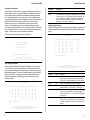
Fast SwitcHub-8mi SNMP Advanced Reference Guide ES3508-TX E0398-R01 150849-101 Copyright © 1998 by Accton Technology Corporation. All rights reserved. No part of this document may be copied or reproduced in any form or by any means without the prior written consent of Accton Technology Corporation. Advanced Reference Guide Accton makes no warranties with respect to this documentation and disclaims any implied warranties of merchantability, quality, or fitness for any particular purpose. The information in this document is subject to change without notice. Accton reserves the right to make revisions to this publication without obligation to notify any person or entity of any such changes. Fast SwitcHub-8mi SNMP Intelligent Fast Ethernet Switch with 8 10BASE-T/100BASE-TX Ports and On-board SNMP Management Agent International Headquarters No. 1 Creation Road III, Science-based Industrial Park Hsinchu 300, Taiwan, R.O.C. Phone: 886-3-5770-270 FAX: 886-3-5770-267 BBS: 886-3-5770-654 Internet: [email protected] USA Headquarters 1962 Zanker Road San Jose, CA 95112 Phone: 408-452-8900 FAX: 408-452-8988 BBS: 408-452-8828 FAST FAX: 408-452-8811 Accton is a trademark of Accton Technology Corporation. Other trademarks or brand names mentioned herein are trademarks or registered trademarks of their respective companies. ES3508-TX E0398-R01 150849-101 Fast SwitcHub-8mi SNMP Contents Advanced Reference Guide Introduction Introduction 1 Making the Connections Required for System Configuration Onsite Connection Modem Connection Telnet Connection In-Band Network Connection 1 1 1 2 2 Configuring Your System with the On-Board Program 2 The on-board management agent in the Fast SwitcHub-8mi SNMP provides the switch with advanced management capabilities. The SwitcHubs SNMP agent module includes a menu-driven configuration program that can be accessed by connecting a terminal or PC to the serial port on the rear panel. You can also access the configuration program by an in-band Telnet connection, or perform in-band management from any network management station running SNMP management software (e.g., AccView/Open). The on-board configuration program allows you to perform the following tasks: Enable/disable any port Set the communication mode for any port Set the switching mode Configure SNMP parameters Configure VLAN port grouping Enable and configure the Spanning Tree Algorithm Restart the system Using the System Configuration Program Performing Basic Configuration Changing the System Configuration Assigning SNMP Parameters Changing System Passwords Port Grouping Configuration Configuring Port Parameters Using the Spanning Tree Algorithm Configuring the Out-of Band Console 3 4 4 6 8 8 9 10 13 Displaying Statistics and Configuration Data Displaying a Description of the Switch Displaying Switch and Port Statistics Displaying the Address Table Displaying Port Status Viewing the Current Spanning Tree Configuration 14 14 14 16 16 17 Downloading System Software Using TFTP Protocol to Download over the Network Using the Serial Port to Download Out-of-Band 18 18 19 Resetting the System 19 It also describes how to access the on-board SNMP agent over the network from a network management station (NMS) using network management software. Logging Off the System 20 Onsite Connection Troubleshooting Telnet Access 20 20 Pin Assignments for Serial Port Connections DB9 Serial Port Pin Description DB9 Port Pin Assignments Connecton from Switchs 9-Pin Serial Port to PCs 9-Pin COM Port Connecton from Switchs 9-Pin Serial Port to Modems25-Pin DCE Port Connecton from Switchs 9-Pin Serial Port to PCs 25-Pin DTE Port 20 20 21 21 21 21 Making the Connections Required for System Configuration The SwitcHub provides a menu-driven configuration program. Also the SNMP agent allows you to manage the switch from any PC attached to the network using in-band network management software (e.g., AccView/Open). Note: Limited configuration (i.e., selecting the port transmission mode) and panel display selection can be carried out with the Configure button on the front panel. (Refer to the Quick Installation Guide.) This section describes how to access the menu-driven configuration program via: Onsite connection - A terminal or workstation directly connected to the serial port on the switch. Modem connection - A workstation connected to a remote SwitcHub via modems. Telnet connection - A workstation connected to a remote SwitcHub via a network Telnet connection. Attach a VT100 compatible terminal or a PC running a terminal emulation program to the serial port on the SwitcHubs rear panel. Use the null-modem cable provided with the product package, or use a null modem cable that complies with the wiring assignments shown in the back of this guide. When attaching to a PC, set terminal emulation type to VT100, specify the port used by your PC (i.e., COM 1~4), and then set communications to 8 data bits, 1 stop bit, no parity, and 9600 bps. Also be sure to set flow control to "none." Modem Connection Configure the SwitcHub Site: Connect the switch's DB9 port to the modem's serial port using standard cabling. For most modems which use a 25-pin port, you will have to provide an RS232 cable with a 9-pin connector on one end and a 25-pin connection on the other end. You do not have to set the modem at the switch's site, because the switch will automatically configure it to auto-answer mode. 1 Fast SwitcHub-8mi SNMP Advanced Reference Guide Configure the Remote Site: At the remote site, connect the PC's COM port (COM 1~4) to the modem's serial port. Set terminal emulation type to VT100, specify the port used by your PC (i.e., COM 1~4), and then set communications to 8 data bits, 1 stop bit, no parity, 9600 or 19200 bps and no flow control. If this is your first time to log into the configuration program, then the default passwords are still "admin" and "guest." The admin password provides administrator rights with Read/Write access to all configuration parameters and statistical information. While the guest password provides observer rights with Read Only access to the management program. Type "admin" at this time and press <Enter> to open the Main Menu. Telnet Connection Prior to accessing the switch via an in-band Telnet connection or in-band management software (e.g., AccView/Open), you must first configure it with a valid IP address, subnet mask, and default gateway using an out-of-band connection. After configuring the switch's IP parameters, you can Telnet into its on-board menu-driven configuration program from anywhere within the attached network. Note: Only one Telnet connection at a time is supported. If one Telnet session already exists, a second Telnet connection will not be able to log into the system. In-Band Network Connection The in-band network management station is the personal computer used to run your network management software. If proper network connections are available, you can access the on-board management agent from anywhere in the attached network. However, prior to accessing the SwitcHub via network management software, you must first configure it with a valid IP address, subnet mask, and default gateway using an out-of-band connection or the BOOTP protocol. Note that the on-board program configuration functions only provide access to the switch's private MIB. To access the full range of SNMP management functions, you must use network management software. Note: To access the full range of SNMP mangement functions, you must use SNMPbased network mangement software. Accton provides Windows-based SNMP software called AccView/Open. Note that AccView/Opens Fast SwitcHub-8mi SNMP Manager software can also be easily integrated into most third-party management platforms. Configuring Your System with the On-board Program Once the connection is established, the login screen for the on-board configuration program appears as shown below. AAAAAAAAA AAAAAAAAAAAA AAAAAA AAAAA AAAAAA AAAAA AAAAAA AAAAA AAAAAA AAAAA AAAAAA AAAAA AAAAAA AAAAA AAAAAA AAAAAAAAA AAAAAA AAAAAAAAAA CCCCCCC CC CC CC CC CC CC CCCCCCC CCCCCCC TTTTTTTTTT OOOOOO CC CC TT OO OO CC TT OO OO CC TT OO OO CC CC TT OO OO CCCCCCC TT OOOOOO Main Board Main Board Agent Module Agent Module : Version Version Version Version 1.0 1.0 2.0 1.2 Type password, then press <ENTER> 2 Configuration parameters are described in the following section. Notes: 1. Only one connection with administrator rights is allowed to log into the system at one time. If one administrator session already exists, a second connection with administrator rights will not be able to log in to the system. 2. A user is allowed three attempts to enter the correct password; on the third failed attempt the user will be locked out of the system. Using the System Configuration Program With the system configuration program you can define system parameters, manage and control the switch and its associated ports, or monitor network conditions. The figure below of the Main Menu and the following table briefly describe the selections available from this program. Note: Input options for the currently selected item are displayed in the highlighted area at the bottom of the interface screen. Main Menu Information & Statistics : System Information... Statistics... Spanning Tree Information... Port Status... Address Table... Configuration : System Configuration... SNMP Configuration... Password Configuration... Virtual LAN Configuration... Port Configuration... Spanning Tree Configuration... Console Configuration... Download & Reset : TFTP Download... Reset... Serial Download LOGOFF NN NN NNN NN NN NN NN NN NN NN NN NNN NN NN Fast SwitcHub-8mi SNMP (c) Copyright Accton Technology Corp., 1997-All rights reserved. Hardware Firmware Hardware Firmware Password You should define a password, record it and put it in a safe place. Select Password Configuration from the Main Menu and enter a password. Note that passwords can consist of up to 24 alphanumeric characters and are not case sensitive. Enter System Information Screen Use cursor keys to choose item. Press <ENTER> to confirm choice. Press <CTRL><N> for quick exit and logoff Menu Description Configuration System Configuration Identifies system by name, location and contact. Also shows basic IP setup. SNMP Configuration Configures communities and trap managers. Password Configuration Sets Administrator and User passwords. Virtual LAN Configuration Assigns switch ports to form up to eight independent LAN groups. 3 Fast SwitcHub-8mi SNMP Menu Port Configuration Description Advanced Reference Guide (continued) System Configuration Disables/enables any port; sets communication mode to autonegotiation, full duplex or half duplex; sets the aging time for entries in the address table, the processing scheme for forwarding packets to adaptive cut-through, cut-through, fragment-free cut-through, or storeand-forward; and enables/disables flow control. System Name System Location System Contact Fast SwitcHub-8mi SNMP MIS Accton Technical Support Dept. Spanning Tree Configuration Enables/disables Spanning Tree Algorithm; also sets parameters for switch priority, hello time, maximum message age, and forward delay; as well as port priority and path cost. IP Address Default Gateway Subnet Mask IP State Send Ping 192.72.24.31 192.72.24.202 255.255.255.0 BootP When Needed Console Configuration Return to Previous Menu Sets the communication parameters for the serial port, including baud rate and console time-out. Information & Statistics Return to Main Menu Use cursor keys to choose item. Press <ENTER> to confirm choice. Press <CTRL><N> to return to the Main Menu System Information Provides detailed system description, including MAC address, MIB identifier, network interface type, and other basic system information. Statistics Shows statistics for the whole switch or for each port, including lost frames, dropped frames, and currently active stations. Spanning Tree Information Displays full listing of parameters for Spanning Tree Algorithm. Name Port Status Shows the operational state for each port, including enable/disable, link status, transmission speed and mode, forwarding scheme, and flow control System Description Address Table Shows the current addresses associated with each port. Download & Reset TFTP Download Downloads new version of firmware to update your system (via inband). Serial Download Downloads new firmware to update your system (via on-board program). Reset Resets hardware or configuration parameters, or clears port address table. LOGOFF System Name Name assigned to the SwitcHub system (max. 30 alphanumeric characters). System Location Specifies the area or location where the system resides (max. 30 alphanumeric characters). System Contact Contact person for the system (max. 30 alphanumeric characters). IP Configuration IP Address IP address of the agent you're managing. The SwitcHub system supports SNMP over UDP/IP transport protocol. In this environment, all systems on the Internet, such as network interconnection devices and Network Management Stations (e.g., a PC running AccView/Open) are assigned an IP address. Valid IP addresses consist of four numbers, of 0 to 255, separated by periods, anything outside of this format will not be accepted by the configuration program. Default Gateway Gateway used in passing trap messages from the SwitcHub agent to the management station. Subnet Mask Subnet mask of the agent you've selected. This mask identifies the host address bits used for routing to specific subnets. IP State Specifies whether or not the IP address is set by the Boot Protocol (BOOTP). Options include: Exits the configuration program and discontinues communications. Performing Basic Configuration After initially logging onto the system, use the Configuration menu to adjust the communication parameters for your console to ensure a reliable connection. Next, set the Administrator and User passwords. Remember to record them in a safe place. Then set the community string which controls access to the on-board SNMP agent via in-band management software. IP Disabled - The switch will not process any IP or Address Resolution Protocol (ARP) frames it receives. It will not respond to SNMP, Ping, Telnet or ARP frames that are received. The other items provided by the Configuration menu are used to set specific communication parameters for individual ports, and to fine-tune the performance of your switch by adjusting the forwarding mode, flow control, and specific Spanning Tree parameters. Each setup screen provided by the Configuration menu is described in the following sections. BOOTP When Needed - If a non-zero IP address has been stored in EEPROM, IP is enabled and will function immediately. However, if the IP address in EEPROM is zero (0.0.0.0), the switch will broadcast BOOTP requests to try to learn its IP address. This is the only IP function that will work until it receives a response. This is the default option. Changing the System Configuration Use the System Configuration screen to display and modify descriptive information about the switch, or to configure the switch's Internet Protocol (IP) parameters. This screen, as seen below, is described in the following table. BOOTP Always - IP is enabled, but will not function until a BOOTP reply has been received. If a non-zero IP address is stored in EEPROM, it will be cleared to zero when the switch is booted. Send Ping 4 Description Sends ICMP echo request to specified site. Ping is used to see if another site on the internet can be reached. 5 Fast SwitcHub-8mi SNMP Advanced Reference Guide BOOTP - When BOOTP is selected, the switch repeats requests at regular intervals, until it receives a valid reply. The requests will cease if a valid IP address is configured or the IP state is set to IP Disabled. Community Strings Index Community Names Mode --------------------------------------------------1 public Read/Write Once the switch stops sending BOOTP requests, it does not resume sending requests or recognize BOOTP responses unless the switch is reset. The parameters in a BOOTP response that are recognized and recorded in the switch's EEPROM are: IP Address Default Gateway Subnet Mask TFTP Boot File Name TFTP Server IP Address Return Add Entry Delete Entry Change Entry Clear Entry Assigning SNMP Parameters Use the SNMP Configuration screen to display and modify parameters for the Simple Network Management Protocol (SNMP). The switch includes an on-board SNMP agent which monitors the status of its hardware, as well as the traffic passing through its ports. A computer attached to the network, called a Network Management Station (NMS), can be used to access this information. Access rights to the on-board agent are controlled by community strings. To communicate with the switch, the NMS must first submit a valid community string for authentication. The options for configuring community strings and related trap functions are described in the following figures and table: Return to SNMP Configuration Screen Use cursor keys to choose item. Press <ENTER> to confirm choice. Press <CTRL><N> to return to the Main Menu Trap Receivers Index IP Address Community Names ---------------------------------------------------------1 192.72.24.119 public SNMP Configuration Send Authentication Traps Yes Community Strings... Return Add Entry Delete Entry Change Entry Clear Entry Trap Receivers... Return to Previous Menu Return to SNMP Configuration Screen Use cursor keys to choose item. Press <ENTER> to confirm choice. Press <CTRL><N> to return to the Main Menu Name Return to Main Menu Use cursor keys to choose item. Press <ENTER> to confirm choice. Press <CTRL><N> to return to the Main Menu Description Send Authentication Traps Issue a trap message whenever authentication of an SNMP request fails. The default is to issue traps to specified receiver stations. Community Strings 1 The community strings authorized for trap management access. All community strings used for IP Trap Managers must be listed in this table. Up to 8 community names may be entered. Community Name A community entry authorized for trap management access (maximum 30 characters). Mode Trap Receivers Management access is restricted to Read or Read/Write. IP management stations selected to receive trap messages from the system. Up to 8 trap receivers may be entered in this table. IP Address IP address of the management station. Community Name The community string required for trap management access (maximum 30 characters). 1 - This switch provides a default community string of "Public" with Read/Write access. 6 7 Fast SwitcHub-8mi SNMP Advanced Reference Guide Changing System Passwords Parameter Description Use the Password Configuration screen to display and modify passwords for the onboard configuration program. There are two user types, "Administrator" and " Normal User," the access privilege is Read/Write for Administrator and Read Only for Normal User. The default passwords are "Admin" and "Guest." Only the Administrator has write access for parameters governing the SNMP agent. You should therefore assign a password to the Administrator as soon as possible, and store it in a safe place. Port Port number on the switch. Group1 - 8 You can configure up to a maximum of 8 independent groups. Ports can belong to more than one group. "Yes" indicates that the port has been assigned to that group, "No" indicates it is not assigned. The default is all ports assigned to Group1 only. Note that the Spanning Tree Algorithm will be automatically disabled if two or more groups are configured. Passwords can consist of up to 24 alphanumeric characters and are not case sensitive. The configuration program will allow a user three attempts at entering a correct password before locking the user out by terminating the connection. If for some reason your password is lost, or you can not gain access to the System Configuration Program, you should contact your Accton distributor for assistance. Configuring Port Parameters Use the Port Configuration screen to configure any port on the switch. In addition to the functional parameters listed in the table below, note that you can also enable/disable any port. The Password Configuration screen appears as shown below. Port Configuration Password Configuration Port Enabled Duplex AgingTime SwitchingMode FlowControl -------------------------------------------------------------1 Yes Auto 300 A-CT Yes 2 Yes Full 300 A-CT Yes 3 Yes Full 300 CT Yes 4 Yes Auto 300 A-CT No 5 Yes Auto 300 FgFree No 6 Yes Auto 300 CT Yes 7 Yes Half 300 A-CT Yes 8 Yes Half 300 A-CT Yes Set Administrator Password Set Normal User Password Return to Previous Menu input old administrator password : Return to Previous Menu Change password of the Administrator Press <CTRL><X> to cancel. Press <ENTER> to accept changes. Port Grouping Configuration Use the Virtual LAN Configuration: Port Grouping Configuration screen to assign any port on the switch to any of up to eight LAN groups. In conventional networks with routers, broadcast traffic is split up into separate domains. Switches do not inherently support broadcast domains. This can lead to broadcast storms in large networks that handle a lot of IPX traffic. Port grouping can be used to create broadcast domains, confining broadcast traffic to the originating group, and providing a much cleaner network environment. Port Grouping Configuration Port Group1 Group2 Group3 Group4 Group5 Group6 Group7 Group8 -------------------------------------------------------------------1 Yes No No No No No No No 2 Yes No No No No No No No 3 Yes No No No No No No No 4 Yes Yes No No No No No No 5 No Yes No No No No No No 6 No Yes No No No No No No 7 No Yes No No No No No No 8 No Yes No No No No No No Return to Previous Menu Return to Main Menu Use cursor keys to choose item. Press <ENTER> to confirm choice. Press <CTRL><N> to return to the Main Menu Parameter Default Description Enabled Yes Allows you to disable a port due to abnormal behavior (e.g., excessive collisions), and then re-enable it after the problem has been resolved. You may also disable a port for security reasons. Duplex Auto Ports support auto-negotiation, full duplex, and half duplex. Aging Time 300 secs. The time-out period in seconds for aging out dynamically learned forwarding information. The input range is 0 - 43200 seconds. Switching Mode A-CT Sets the method for forwarding packets to "cut-through (CT)," "fragment-free cut-through (FgFree)," "adaptive cut-through (A-CT)," or "store and forward (S & F)." For details, see Switching Methods on the next page. Flow Control yes Used to enable or disable flow control. Flow control relies on back pressure, which can eliminate frame loss by "blocking" traffic from end stations or segments connected directly to the switch when its buffers fill. Return to Virtual LAN Configuration Screen Use cursor keys to choose item. Press <ENTER> to confirm choice. Press <CTRL><N> to return to the Main Menu 8 9 Fast SwitcHub-8mi SNMP Communication Mode - If you use auto-negotiation, be sure the attached device also supports this mode. If any device attached to the switch runs at full duplex, but does not support auto-negotiation, you will need to manually set the communication mode to full duplex. However, once set, the communication mode setting will remain unchanged, even if the link is broken (e.g., by unplugging the cable, or by a power reset). To restore auto-negotiation after manually selecting half or full duplex, use the Configure button, on-board management program, or SNMP network management software to set the communication mode to auto-negotiation. Notes: 1. Full duplex can only be used for a dedicated link. When connecting to a shared collision domain (e.g., a repeater hub) be sure the transmission mode is set for half-duplex. 2. The de facto standard for auto-negotiation is used in this switch. Advanced Reference Guide selects a root port on each bridging device (except for the root device) which incurs the lowest path cost when forwarding a packet from that device to the root device. Then it selects a designated bridging device from each LAN which incurs the lowest path cost when forwarding a packet from that LAN to the root device. All ports connected to designated bridging devices are assigned as designated ports. After determining the lowest cost spanning tree, it enables all root ports and designated ports, and disables all other ports. Network packets are therefore only forwarded between root ports and designated ports, eliminating any possible network loops. The following figure gives an illustration of how the Spanning Tree Algorithm assigns bridging device ports. Switching Methods - The SwitcHub employs a dynamic forwarding architecture that enables it to support the following switching modes, "adaptive cut-through," "cutthrough," "fragment-free cut-through," and "store-and-forward." The function of each of these switching methods can be described as follows. Cut-through: A packet is forwarded as soon as the 6-byte destination address in the packet header has been scanned, it does not wait until the entire packet has been received. This technique, which requires the least processing time, reduces the latency of packet transmission to 20 microseconds or less. Fragment-free cut-through: A packet is forwarded only after the first 64 bytes have been received. This prevents runts from being passed along, effectively cleaning up the data stream. This mode is beneficial when it is probable that the collision rate will be high (i.e., when the switch is used to interconnect several shared segments, each having a large number of end stations). Store-and-forward: An entire packet is received into a buffer so it can be checked for validity before being forwarded to another port. This prevents errors from being propagated throughout the network. Adaptive cut-through: This method utilizes Accton's smart algorithm to dynamically change between switching modes based on the current CRC error rate. Switching starts with standard cut-through for a clean data environment, changes to fragmentfree cut-through for a higher error rate, and then to store-and-forward for a highly contentious environment. To ensure that you can manage any network load without manual intervention, adaptivecut-through is used as the default switching method. By using this method, the SwitcHub delivers the best network performance under any environment. Using the Spanning Tree Algorithm The Spanning Tree Algorithm (i.e., the STA configuration algorithm as outlined in IEEE 802.1D) can be used to detect and disable network loops, and to provide link backup. This allows the switch to interact with other bridging devices (i.e., STA compliant switch, bridge or router) in your network to ensure that only one route exists between any two stations on the network. If redundant paths or loops are detected, one or more ports are put into a blocking state (i.e., stopped from forwarding packets) to eliminate the extra paths. Moreover, if one or more of the paths in a stable spanning tree topology fail, this algorithm will automatically change ports from blocking state to forwarding state to reestablish contact with all network stations. Configurable STA parameters can be seen in the figure below and are described in the following table. Spanning Tree Configuration Spanning Tree Algorithm Priority 32768 Hello Time 2 Maximum Message Age Forward Delay Yes 20 15 Port Priority Path Cost ----------------------------------------------------1 128 10 2 128 10 3 128 10 4 128 10 5 128 10 6 128 10 7 128 10 8 128 10 Return to Previous Menu Take Effect immediately Return to Main Menu Use cursor keys to choose item. Press <ENTER> to confirm choice. Press <CTRL><N> to return to the Main Menu The STA uses a distributed algorithm to select a bridging device (i.e., STA compliant switch, bridge or router) that serves as the root of the spanning tree network. It 10 11 Fast SwitcHub-8mi SNMP Parameter Default Description Switch Spanning Tree Algorithm Enabled Enable this parameter to participate in an STA compliant network. Priority 32,768 Device priority is used in selecting the root device, root port, and designated port. The device with the highest priority becomes the STA root device. However, if all devices have the same priority, the device with the lowest MAC address will then become the root device. Advanced Reference Guide Parameter Default Description Path Cost 10 or 100 This parameter is used by the STA algorithm to determine the best path between devices. Therefore, lower values should be assigned to ports attached to faster media, and higher values assigned to ports with slower media. The default is automatically set (depending on the negotiated transmission speed) according to the following formula: Recommended Path Cost = 1000/(LAN speed in Mbps); i.e., default is set at 10 for Fast Ethernet or 100 for standard Ethernet. Enter a value from 0 - 65535. Remember that the lower the numeric value, the higher the priority. Hello Time 2 The time interval (in seconds) at which the root device transmits a configuration message. The minimum value is 1. The maximum value is the lower of 10 or [(Max. Message Age / 2) -1]. Maximum Message Age 20 The maximum time (in seconds) a device can wait without receiving a configuration message before attempting to reconfigure. All device ports (except for designated ports) should receive configuration messages at regular intervals. Any port that ages out STA information (provided in the last configuration message) becomes the designated port for the attached LAN. If it is a root port, a new root port is selected from among the device ports attached to the network. The range is 0 - 65535. Note: Path cost takes precedence over port priority. Note: For a listing of the current STA settings, refer to the Spanning Tree Information screen under the Information & Statistics menu. Configuring the Out-of-Band Console You can access the on-board configuration program by attaching a VT100 compatible device to the switch's serial port. (For more information on connecting to this port, refer to the section on Making the Connections Required for System Configuration on page 2.) The communication parameters for this port are accessed from the Console Configuration screen seen below and described in the following table. Console Configuration The minimum value is the higher of 6 or [2 x (Hello Time + 1)]. The maximum value is the lower of 40 or [2 x (Forward Delay 1)]. Forward Delay 15 (continued) Console Baudrate 9600 Console Time-Out (in Minutes) 5 The maximum time (in seconds) the root device will wait before changing states (i.e., listening to learning to forwarding). This delay is required because every device must receive information about topology changes before it starts to forward frames. In addition, each port needs time to listen for conflicting information that would make it return to a blocking state; otherwise, temporary data loops might result. Return to Previous Menu The minimum value is the higher of 4 or [(Max. Message Age / 2) + 1]. Return to Main Menu Use cursor keys to choose item. Press <ENTER> to confirm choice. Press <CTRL><N> to return to the Main Menu The maximum value is 30. Port Priority 128 Defines the priority for the use of a port in the STA algorithm. If the path cost for all ports on a switch are the same, the port with the highest priority (i.e., lowest value) will be configured as an active link in the spanning tree. Where more than one port is assigned the highest priority, the port with lowest numeric identifier will be enabled. The range is 0 - 255. 12 Parameter Default Description Console Baud Rate 9600 bps The rate at which data is sent between devices. Supported baud rates are 9600, 19200 bps and autobaud. Console Time-Out 5 minutes If no input is received from the attached device after this interval (in minutes), the current session is automatically closed. Range: 0 - 60 minutes; where 0 indicates disabled. 13 Fast SwitcHub-8mi SNMP Advanced Reference Guide Displaying Statistics and Configuration Data Displaying a Description of the Switch Use the System Information screen to display descriptive information about the switch, or for quick system identification. This screen is detailed in the figure below and the following table describing the displayed parameters: System Information System Description MAC Address Interface Description System Name System Location System Contact System Up Time No of Reset Since Power On Statistics Time Since Last Reset Port 1 Statisitcs: No of Reset Port 1 Statistics Since Power On: Local Frames Received 3244 Forwarded Frames 1234 Learning Broadcast Frames 12 Long Frames 39 Short Frames 19 Collisions 205 Intelligent Fast Ethernet Switch 00:00:E8:44:20:04 Accton MPX2 Ver 1.0 Fast SwitcHub-8mi SNMP MIS Accton Technical Support Dept. 19Day, 2Hr, 41Min, 5Sec 1 Return Display 11Day 10Hr 30Min 30Sec 1 CRC Errors Input Queue Frame Lost Output Queue Frame Lost No of Frames in Input Queue No of Frames in Output Queue Currently Active Stations Refresh Screen 205 0 0 20 6 86 Reset Statistics Return to Main Menu Use cursor keys to choose item. Press <ENTER> to confirm choice. Press <CTRL><N> to return to the Main Menu Return to Previous Menu Return to Main Menu Use cursor keys to choose item. Press <ENTER> to confirm choice. Press <CTRL><N> to return to the Main Menu Parameter Description System Description System hardware description. MAC Address Hardware address for the switch. Interface Description Firmware name and version used in transceiver chips. System Name Name assigned to the switch system (maximum 30 characters). System Location Specifies the area or location where the system resides (maximum 30 characters). System Contact Contact person for the system (maximum 30 characters). System Up Time Length of time the switch management agent has been running. No. of Reset Since Power On Number of times the switch has been reset. Name Description Local Frames Received Number of frames confined to this segment and not forwarded by the switch. Forwarded Frames Number of frames forwarded to another segment. Learning Broadcast Frames Number of learning broadcast frames received on this port. Long Frames Number of times frame length has exceeded the maximum allowable size (i.e., 1518 bytes). Short Frames Number of frames less than 64 bytes long. Collisions Number of simultaneous node transmissions detected by this port. CRC Errors Number of CRC errors. Input Queue Frame Lost Number of frames lost because the input queue is full. Output Queue Frame Lost Number of frames lost because the output queue is full. No. of Frames in Input Queue Number of frames in the input queue. No. of Frames in Output Queue Number of frames in the output queue. Currently Active Stations Number of entries in the address table (i.e., the sum of all stations listed by this port, regardless of whether they belong to the local segment or to another segment). Displaying Switch and Port Statistics Use the Statistics screen to display key statistics for each port or the whole switch. The Statistics screen displays overall statistics on the traffic passing through each port, as well as the number of currently active stations. This information can be used to identify potential problems with the switch (e.g., a faulty port). The values displayed have been accumulated since the last system reboot or counter reset. Use the command options provided by the menu bar at the bottom of the screen. Select "Display" to view statistics for each individual port or the whole switch, or "Refresh" to update the displayed statistics from the MIB. Statistical values displayed by this screen are indicated in the following figure and table. 14 15 Fast SwitcHub-8mi SNMP Advanced Reference Guide Displaying the Address Table Parameter Description The Address Table contains the MAC addresses associated with each port. (i.e., address and associated source port). To access information in the address tables, use the command options provided by the menu bar at the bottom of the screen. Use the "Display" command to select a port, "More" to scroll through a long listing, or "Search" to find a specific address. The fields displayed by this screen are indicated in the following figure and table. Enabled1 Shows if the port is enabled or not. Link Indicates if a device is attached to the port and transmitting a link pulse signal. Speed Shows if the port connection is operating at 10 or 100Mbps. Port speed is automatically set to match the speed of the attached device. Duplex 1 Shows if the port is currently operating at full duplex or half duplex. AgingTime 1 Time in seconds after which unused addresses will be discarded from the port's address table. Switching Mode 1 Shows the method used for forwarding packets as "cut-through," "fragment-free cutthrough," "adaptive cut-through," or "store and forward." (See Switching Methods 0n page 11 for a more detailed description of these methods.) Flow Control 1 Shows if flow control is enabled or disabled. Flow control uses back pressure, which can eliminate frame loss by "blocking" traffic from end stations or segments connected directly to the switch when its buffers fill up. Address Table Time Since Last Clear Port 1 Address Table : 19Day, 3Hr, 43Min, 38Sec No of Clear Port 1 Address Table Since Power On : 1 Address Port -------------------------00 00 E8 C0 00 01 1 00 00 E8 C1 23 56 1 00 00 E8 C0 10 51 1 00 00 E8 00 42 15 1 00 00 E8 C0 60 01 1 00 00 E8 C5 23 45 1 00 00 E8 C5 23 55 1 00 00 E8 C5 23 65 1 00 00 E8 C5 23 75 1 Return Address Port -------------------------00 00 E8 C0 00 51 1 00 00 E8 C1 23 26 1 00 00 E8 C0 13 81 1 00 00 E8 C0 42 25 1 00 00 E8 C0 61 04 1 00 00 E8 C1 24 33 1 --- End of Address Tables --- 1 - Use the Port Configuration screen to change this parameter. Viewing the Current Spanning Tree Configuration Display More Search Return to Main Menu Use cursor keys to choose item. Press <ENTER> to confirm choice. Press <CTRL><N> to return to the Main Menu The Current Spanning Tree Information screen displays a summary of the Spanning Tree configuration for each port. To make any changes to the parameters for the Spanning Tree, use the Configuration Menu. Also note that this screen cannot be accessed unless you have already enabled the Spanning Tree Algorithm via the Configuration Menu. The parameters shown in this screen are indicated in the following figure and table. Current Spanning Tree Information Name Description Address The MAC address of a node. Source Port The port whose address table includes this MAC address. Hello Time : 2 Max message Age : 20 Forward Delay : 15 Root : 32768.0000E8C00001 Root Port : 1 Root Cost : 20 Topology Change Count : 1 Time Since Last Topology Change : 0Day, 9Hr, 9Min, 0Sec Port State DesignatedCost DesignatedBridgeID DesignatedPort -----------------------------------------------------------------------1 Disabled 128 32769.0000E8C02004 128.1 2 Blocking 128 32770.0000E8C02008 128.1 3 Listening 128 32771.0000E8C02010 128.1 4 Learning 128 32772.0000E8C02018 128.1 5 Forwarding 128 32773.0000E8C02020 128.1 6 Forwarding 128 32774.0000E8C02028 128.1 7 Learning 128 32775.0000E8C02038 128.1 8 Listening 128 32776.0000E8C02040 128.1 Displaying Port Status The Port Status screen displays the current status for each port on the switch. If you need to modify the connection parameters or switch processing scheme for any port, refer to the earlier section on Configuring Port Parameters. The fields displayed by this screen are indicated in the following figure and table. Port Status Return to Previous Menu Port Enabled Link Speed Duplex AgingTime SwitchingMode FlowControl --------------------------------------------------------------------------1 Yes up 100M Full 300 A-CT Yes 2 Yes up 100M Full 300 A-CT Yes 3 Yes up 100M Full 300 CT Yes 4 Yes up 100M Full 300 A-CT Yes 5 Yes up 100M Full 300 FgFree Yes 6 Yes up 100M Full 300 A-CT Yes 7 Yes down 100M Half 300 CT Yes 8 Yes down 100M Half 300 CT Yes Return to Previous Menu Return to Main Menu Use cursor keys to choose item. Press <ENTER> to confirm choice. Press <CTRL><N> to return to the Main Menu 16 Return to Main Menu Use cursor keys to choose item. Press <ENTER> to confirm choice. Press <CTRL><N> to return to the Main Menu Parameter Description Hello Time The time interval (in seconds) at which the root device transmits a configuration message. Forward Delay The maximum time (in seconds) the root device will wait before changing states (i.e., listening to learning to forwarding). Root Port The number of the port on this switch that is closest to the root. This switch communicates with the root device through this port. If there is no root port, then this switch has been accepted as the root device of the spanning tree network. 17 Fast SwitcHub-8mi SNMP Parameter Description Max. Message Age The maximum time (in seconds) a device can wait without receiving a configuration message before attempting to reconfigure. Root The priority and MAC address of the device in the spanning tree that this switch has accepted as the root device. Advanced Reference Guide (continued) TFTP Download TFTP Server Address 192.72.24.17 Download Filename es3508.bin Root Cost The path cost from the root port on this switch to the root device. Execute Network Download Topology Change Count The number of times a switch port has entered the forwarding state, plus the number of times a port has changed from forwarding to blocking. This counter is reset when the switch is reset or the spanning tree is turned on. Return to Previous Menu Time Since Last Topology The time since a switch port last entered the forwarding state, or made a transition Change from forwarding to blocking. Port The port number on the switch. State Displays the current state of this port within the spanning tree: Disabled Port has been disabled by the user or has failed diagnostics. Blocked Port receives STA configuration messages, but does not forward packets. Listening Learning Parameter Description TFTP Server Address IP address of a TFTP server. Port will leave blocking state due to topology change, starts transmitting configuration messages, but does not yet forward packets. Download Filename The *.bin file to download. Execute Network Download Issues request to TFTP server to download the specified file. Has transmitted configuration messages for an interval set by the Forward Delay parameter without receiving contradictory information. Port address table is cleared, and the port begins learning addresses. Using the Serial Port to Download Out-of-Band Forwarding The port forwards packets, and continues learning addresses. Use the Serial Download command under the Download & Reset menu to update available software in the switch. The download file should be an ES3508 *.bin file from Accton; otherwise the agent will not accept it. If two ports of a switch are connected to the same segment and there is no other STA device attached to this segment, the port with the smaller ID forwards packets and the other is blocked. This command specifies direct download from an attached device via the serial port. You may download using any terminal emulation program that can transmit binary files using Xmodem protocol. Position the highlight cursor over "Serial Download" and press the <Enter> key. After selecting a file and the Xmodem protocol, initiate sending the file from your computer by specifying "send" or "upload" file. The terminal emulation program will display the progress of the download process. After downloading the new software, the agent will automatically restart itself. All ports are blocked when the switch is booted, then some of them change state to listening, to learning, and then to forwarding. Resetting the System The rules defining port status are: A port on a network segment with no other STA compliant bridging device is always forwarding. Designated Cost The cost for a packet to travel from this port to the root in the current spanning tree configuration. The slower the media, the higher the cost. Designated Bridge ID The priority and MAC address of the device through which this port must communicate to reach the root of the spanning tree. Designated Port The port on the designated bridging device through which this switch must communicate with the root of the spanning tree. Downloading System Software Using TFTP Protocol to Download over the Network Use the TFTP Download screen under the Download & Reset menu to load software updates into the switch. The download file should be an ES3508 *.bin file from Accton; otherwise the agent will not accept it. The success of the download operation depends on the accessibility of the TFTP server and the quality of the network connection. After downloading the new software, the agent will automatically restart itself. The parameters shown in this screen are indicated in the following figure and table. 18 Return to Main Menu Use cursor keys to choose item. Press <ENTER> to confirm choice. Press <CTRL><N> to return to the Main Menu Use the Reset command under the Download & Reset menu to reset the system or clear the address table. The information and reset options listed on this screen are detailed in the following figure and table. Reset Display Diagnostics While Power-On Yes Reset Unit with Diagnostics Reset Unit without Diagnostics Clear Address Table Reset EEprom to Factory Default Value Return to Previous Menu Return to Main Menu Use cursor keys to choose item. Press <ENTER> to confirm choice. Press <CTRL><N> to return to the Main Menu 19 Fast SwitcHub-8mi SNMP Parameter Description Display Diagnostics While Power-On Diagnostic indicators can be enabled/disabled during a hard reset. Reset Unit with Diagnostics Resets the unit and runs diagnostics. Clears all counters and restores configuration parameters from nonvolatile memory. The full process requires about 30 seconds. Reset Unit without Diagnostics Resets the unit without running diagnostics. Clears all counters and restores configuration parameters from nonvolatile memory. Clear Address Table Clears the address table. Reset EEprom to Factory Default Value Resets all counters and restores factory defaults for all configuration parameters. Logging Off the System Use the Logoff command under the Main Menu to exit the System Configuration Program and end all communications with the switch for that session. Troubleshooting Refer to the Quick Installation Guide for a more detailed listing of troubleshooting procedures. However, if you have trouble making a Telnet connection, then please refer to the following section. Telnet Access You can Telnet into the switch from anywhere within the attached network. However, you must first configure the switch with a valid IP address, subnet mask, and default gateway. If you have trouble establishing a link to the on-board menu-driven configuration program, check to see if you have a valid network connection. Then verify that you entered the correct IP address from your remote Telnet location. Also, be sure the port through which you are connecting to the switch has not been disabled. (See Configuring Port Parameters on page 10.) If it has not been disabled, then check the network cabling that runs between your remote Telnet site and the switch. Note: Only one Telnet connection at a time is supported. If one Telnet session already exists, a second Telnet connection will not be able to log into the system. Pin Assignments for Serial Port Connections DB9 Serial Port Pin Description The DB9 serial port on the SwitcHub rear panel is used to connect the switch to a management device. The on-board menu-driven configuration program can be accessed from a terminal, a PC running a terminal emulation program, or from a remote location via a modem connection. You can use the management port to configure port settings (e.g., enabled or disabled), or to update device firmware. The pin assignments used to connect various device types to the switch's management port are provided in the following tables. 20 Advanced Reference Guide DB9 Port Pin Assignments EI A Circuit CCITT Signal CF BB BA CD AB CC CA CB CE 109 104 103 108.2 102 107 105 106 125 Description DCD (Data Carrie r De te c te d ) RxD (Re c e ive d Data) TxD (Trans mitte d Data) DTR (Data Te rminal Re ad y) SG (Sig nal Gro und ) DSR (Data Se t Re ad y) RTS (Re q ue s t-to -Se nd ) CTS (Cle ar-to -Se nd ) RI (Ring Ind ic ato r) Switch's DB9 DTE Pi n # 1 2 3 4 5 6 7 8 9 PC DB9 DTE Pi n # 1 2 3 4 5 6 7 8 9 Modem DB25 DCE Pi n # 8 3 2 20 7 6 4 5 22 Signal Direction DTE-DCE <--------<-----------------> ---------> --------<-----------------> <--------<--------- Connection from Switch's 9-Pin Serial Port to PC's 9-Pin COM Port Switch's 9-Pin Serial Port 1 DCD 2 RXD 3 TXD 4 DTR 5 SGND 6 DSR 7 RTS 8 CTS 9 RI CCITT Signal ------- DCD -------<----- TXD --------------- RXD ------> ------- DSR ------> ------- SGND ------------ DTR -------------- CTS ------> <------ RTS -------------- RI ----------- PC's 9-Pin COM Port 1 3 2 6 5 4 8 7 9 Connection from Switch's 9-Pin Serial Port to Modem's 25-Pin DCE Port Switch's 9-Pin Serial Port 1 2 3 4 5 6 7 8 9 CCITT Signal <------ DCD ------<------ RXD -------------- TXD ------> -------- DTR ------> -------- SGND ----<------ DSR -------------- RTS ------> <------ CTS ------<------ RI ------- Modem's 25-Pin COM Port 8 3 2 20 7 6 4 5 22 Connection from Switch's 9-Pin Serial Port to PC's 25-Pin DTE Port Switch's 9-Pin Serial Port 1 DCD 2 RXD 3 TXD 4 DTR 5 SGND 6 DSR 7 RTS 8 CTS 9 RI Null Modem 1 2 3 4 5 6 7 9 20 1 3 2 8 20 7 4 5 6 8 3 2 20 7 6 4 5 22 PC's 25-Pin DTE Port DCD TXD RXD DTR SGND DSR RTS CTS RI 21