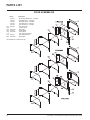
1
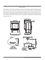
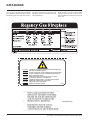
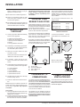
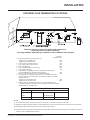
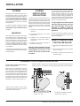
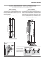
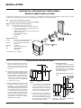
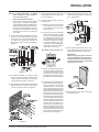
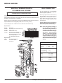
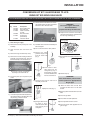
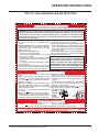
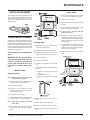
Owners & Installation Manual Freestanding Gas Stove LISTINGS AND CODE APPROVALS These gas appliances have been tested in accordance with AS4553-2000, NZS 5262 and have been certified by the Australian Gas Association for installation and operation as described in these Installation and Operating Instructions. Your unit should be serviced annually by an authorised service person. Models: F37-NG F37-LPG PLEASE KEEP THESE INSTRUCTIONS FOR FUTURE REFERENCE WARNING: Improper installation, adjustment, alteration, service or maintenance can cause injury or property damage. Refer to this manual. For assistance or additional information consult an authorized installer, service agency or the gas supplier. FOR YOUR SAFETY Do not store or use gasoline or other flammable vapours and liquids in the vicinity of this or any other appliance. Installation and service must be performed by an authorized installer, service agency or the gas supplier. 918-533a FOR YOUR SAFETY What to do if you smell gas: Do not try to light any appliance Do not touch any electrical switch: do not use any phone in your building. Immediately call your gas supplier from a neighbour's phone. Follow the gas supplier's instructions. If you cannot reach your gas supplier, call the fire department. 01/06/14 To the New Owner: Congratulations! You are the owner of a state-of-the-art Regency® Rear Flued Room Sealed Freestanding Gas Stove by FPI Fireplace Products International. The Regency® Gas Series of hand crafted appliances has been designed to provide you with all the warmth and charm of a woodstove, at the flick of a switch. The models F37-NG, and F37LPG of this series has been approved by AHD for both safety and efficiency. As it also bears our own mark, it promises to provide you with economy, comfort and security for many trouble free years to follow. Please take a moment now to acquaint yourself with these instructions and the many features of your Regency® Rear Flued Room Sealed Freestanding Gas Stove. 2 F37 Regency® Rear Flued Room Sealed Freestanding Gas Heater TABLE OF CONTENTS DATA BADGE OPERATING INSTRUCTIONS Data Badge ..................................................................4 Operating Instructions .................................................18 Lighting Procedure ......................................................18 Shutdown Procedure ...................................................18 First Fire ......................................................................18 Convection Fan Operation...........................................18 Normal Operating Sounds of Gas Appliances .............18 Copy of the Lighting Plate instructions .......................19 INSTALLATION Important .....................................................................5 Specifications ................................................................5 Before You Start ............................................................5 General Safety Information............................................5 Installation Checklist ......................................................6 Locating Your Regency Gas Stove ................................6 Clearances to Combustibles..........................................6 Combustion and Ventilation Air......................................6 Exterior Flue Termination Locations ..............................7 Planning Your Flueing Installation .................................8 Flueing ...........................................................................8 Flueing Installation Precautions.....................................8 Safety Precautions for the Installer................................8 Flueing Arrangements - Vertical Terminations ..............9 Residential and Manufactured Homes / Mobile Homes Installations ...........................10 Horizontal Installations ................................................10 Vertical Termination with Co-Linear Flex System ........12 Gas Connection ...........................................................12 Conversion from NG to LPG .....................................13 Log Set Installation ......................................................14 Aeration Adjustment ....................................................14 Door Installation...........................................................15 Gas Pipe Pressure Testing ..........................................16 Louvre Installation .......................................................16 Optional Wall Thermostat ...........................................16 Optional Remote Control ............................................17 Wiring ..........................................................................17 Final Check..................................................................17 F37 Regency® Rear Flued Room Sealed Freestanding Gas Heater MAINTENANCE Maintenance Instructions.............................................20 General Flue Maintenance ..........................................20 Log Replacement ........................................................20 Gold-plated Doors .......................................................20 Door Gasket ...............................................................20 Latch Adjustment .........................................................21 Glass Replacement .....................................................21 Fan maintenance .........................................................22 Removing Valve...........................................................22 PARTS LIST Main Assembly ............................................................24 Burner & Log Assembly ...............................................25 Door Assemblies..........................................................26 WARRANTY Warranty ....................................................................27 3 DATA BADGE This is a copy of the label that accompanies each REGENCY Rear Flued Room Sealed Freestanding Gas Stove. We have printed a DO NO T DO NO T DO NO T DO NO T DO NO T DO NO T DO NO T copy of the contents here for your review. The data plate is located on the inside of the drop down pedestal door. NOTE: Regency® units are constantly being improved. Check the label on the unit and if there is a difference, the label on the unit is the correct one. OPERATE THIS APPLIANCE BEFORE READING THE INSTRUCTIONS BOOKLET. PLACE ARTICLES ON OR AGAINST THIS APPLIANCE STORE CHEMICALS OR FLAMMABLE MATERIALS NEAR THIS APPLIANCE. SPRAY AEROSOLS IN THE VICINITY OF THIS APPLIANCE WHILE IN OPERATION. OPERATE WITH PANELS, COVERS OR GUARDS REMOVED FROM THIS APPLIANCE. ENCLOSE THIS APPLIANCE. MODIFY THIS APPLIANCE. 908-602a (Australia Only) 4 F37 Regency® Rear Flued Room Sealed Freestanding Gas Heater INSTALLATION IMPORTANT SAVE THESE INSTRUCTIONS The REGENCY Rear Flued Room Sealed Freestanding Gas Stove must be installed in accordance AG601 and NZS 5261 and with these instructions. Carefully read all the instructions in this manual first. Consult the building authority having jurisdiction to determine the need for a permit prior to starting the installation. Note: Failure to follow the instructions could cause a malfunction of the heater which could result in death, serious bodily injury, and/or property damage. Failure to follow these instructions may also void your fire insurance and/or warranty. SPECIFICATIONS Fuels: F37-NG is approved for use with NG. F37-LPG is approved for use with liquefied petroleum gases (LPG). Electrical: 240 V A.C. system. Circulation Fan: Two Speed Log Sets: Ceramic fibre, 7 per set. Flue System: Axial (6-5/8" outer / 4" inner liner) rigid flue and Riser Vent Terminal. BEFORE YOU START Safe installation and operation of this appliance requires common sense, however, please be aware of the following: INSTALLATION AND REPAIRS SHOULD BE DONE BY AN AUTHORIZED SERVICE PERSON. THIS APPLIANCE SHOULD BE INSTALLED, REPAIRED, INSPECTED BEFORE USE AND AT LEAST ANNUALLY BY AN AUTHORIZED SERVICE PERSON. MORE FREQUENT CLEANING MAY BE REQUIRED DUE TO EXCESSIVE LINT FROM CARPETING, ETC. IT IS IMPERATIVE THAT THE CONTROL COMPARTMENT, BURNERS AND CIRCULATING AIR PASSAGEWAYS OF THE APPLIANCE BE KEPT CLEAN. DUE TO HIGH TEMPERATURES, THE APPLIANCE SHOULD BE LOCATED OUT OF TRAFFIC AND AWAY FROM FURNITURE AND DRAPERIES. WARNING: FAILURE TO INSTALL THIS APPLIANCE CORRECTLY WILL VOID YOUR WARRANTY AND MAY CAUSE A SERIOUS HOUSE FIRE. CHILDREN AND ADULTS SHOULD BE ALERTED TO THE HAZARDS OF HIGH SURFACE TEMPERATURES, ESPECIALLY THE FIREPLACE GLASS, AND SHOULD STAY AWAY TO AVOID BURNS OR CLOTHING IGNITION. YOUNG CHILDREN SHOULD BE CAREFULLY SUPERVISED WHEN THEY ARE IN THE SAME ROOM AS THE APPLIANCE. manufactured home the unit must be bolted down to the floor. 4) We recommend that you plan your installation on paper using exact measurements for clearances and floor protection before actually installing this appliance. Have an authorized building inspector review your plans before installation. GENERAL SAFETY INFORMATION 1) The appliance shall be installed in accordance with the manufacturer's installation instructions, local gas fitting regulations, municipal building codes, water supply regulations, electrical wiring regulations, with AS5601-2004 (AGA gas installation code) NZS 5261 (New Zealand) 2) Installation and repair should be done ONLY by an authorised person. 3) DO NOT CONNECT TO MASONARY FLUE. CLOTHING OR OTHER FLAMMABLE MATERIAL SHOULD NOT BE PLACED ON OR NEAR THE APPLIANCE. 4) This appliance must be connected to the specified flue and termination cap to the outside of the building envelope. Never flue to another room or inside a building. Make sure that the flue is fitted as per Flueing instructions. 1) Provide adequate clearances for servicing, proper operation and around the air openings into the combustion chamber. 5) Inspect the flueing system annually for blockage and any signs of deterioration. 2) The appliance must be installed on a flat, solid, continuous surface (e.g. wood, metal, concrete). This may be the floor, or it can be raised up on a platform to enhance its visual impact. The appliance may be installed on carpeting, tile, wood flooring or other combustible material, because the appliance's metal pedestal base extends the full width and depth of the appliance. The REGENCY Rear Flued Room Sealed Freestanding Gas Stove can be installed in a wide variety of ways and will fit nearly any room layout. It may be installed in a recessed position, framed out into the room, or across a corner. 3) The REGENCY Rear Flued Room Sealed Freestanding Gas Stove is approved for manufactured home installations, see "Locating Your Gas Stove" to "Flueing Installation Precaution" sections for the required flue arrangements. If installed into a F37 Regency® Rear Flued Room Sealed Freestanding Gas Heater 6) Flueing terminals shall not be recessed into a wall or siding. 7) Any safety glass removed for servicing must be replaced prior to operating the appliance. 8) To prevent injury, do not allow anyone who is unfamiliar with the operation to use the fireplace. 9) Wear gloves and safety glasses for protection while doing required maintenance. 10) Be aware of electrical wiring locations in walls and ceilings when cutting holes for termination. 11) Under no circumstances should this appliance be modified. Parts that have to be removed for servicing should be replaced prior to operating this appliance. 12) Installation and any repairs to this appliance should be done by an authorised service person. An authorised service person should be called to inspect this appliance annually. 5 INSTALLATION Make it a practice to have all of your gas appliances checked annually. 13) Do not slam shut or strike the glass door. 14) Under no circumstances should any solid fuels (wood, paper, cardboard, coal, etc.) be used in this appliance. 15) The appliance area must be kept clear and free of combustible materials, (gases and other flammable vapours and liquids). INSTALLATION CHECKLIST 1) Locate your gas stove. Refer to the following sections where applicable: a. Clearances to Combustibles b. Exterior Flue Termination Locations c. Planning Your Flue Installation d. Flueing e. Flueing Installation Precaution CAUTION: Any alteration to the product that causes sooting or carboning that results in damage is not the responsibility of the manufacturer. This unit can be installed on a solid combustible surface like a wood floor. This unit can also be installed directly on carpeting or vinyl when the bottom pedestal cover plate (provided with unit) is installed. LOCATING YOUR REGENCY GAS STOVE Use the minimum clearances shown in the diagrams below: When selecting a location for your stove, ensure that the clearances listed above are met as well as ensuring that there is adequate accessibility for servicing and proper operation. See the "Exterior Flue Termination Locations" section for Flue Termination requirements. This appliance is Listed for bedroom installations when used with a Listed Millivolt Thermostat. Some areas may have further requirements, check local codes before installation. F37-NG & F37-LPG Clearances A Side Wall to Unit 190 mm B Back Wall to Unit 76 mm E Side Wall to Unit 114 mm F37-NG & F37-LPG Reference Dimensions C Floor to Flue Centerline 635 mm D Side Wall to Flue Centerline521 mm This appliance is Listed for Alcove installations, maintain minimum Alcove clearances as follows, minimum ceiling height of 1.7m, minimum width of 1.0m and a maximum depth of 0.9m. 2) Install flueing. Check all fluing requirements. See "Flueing" to "Vertical Termination with Co-Linear Flex System" sections. 3) Make gas connections. Refer to the "Gas Connection" section. Test the pilot. Must be as per diagram in the "Maintenance Instruction" section. 4) If necessary, convert from NG to LPG. Refer to "Conversion Kit from NG to LPG" section. 5) Install standard and optional features. Refer to the following sections where applicable. a. Log Set Installation b. Door Installation c. Louvre Installation d. Optional Wall Thermostat e. Optional Remote Control 6) Test Gas Pressure. Refer to the "Gas Pipe Pressure Testing" section. 7) Final check. Refer to the "Final Check" section. Before leaving this unit with the customer, the installer must ensure that the appliance is firing correctly and operation fully explained to customer. This includes: 1) Clocking the appliance to ensure the correct firing rate (rate noted on label) after burning appliance for 15 minutes. 2) If required, adjusting the primary air to ensure that the flame does not carbon. First allow the unit to burn for 15-20 min. to stabilize. 6 Minimum ceiling height is 914mm from top of unit. A) B) C) D) Cross Corner Flush with Wall/Alcove Flat on Wall Corner Flat on Wall CLEARANCES TO COMBUSTIBLES The clearances listed are MINIMUM distances. Measure the clearance to both the appliance and the chimney connector. The farthest distance is correct if the two clearances do not coincide. For example, if the appliance is set as indicated in one of the diagrams but the connector is too close, move the stove until the correct clearance to the connector is obtained. COMBUSTION AND VENTILATION AIR The combustion air from this appliance is drawn from outside the building through the outer flue. Extra provision for combustion air inside the room is not required. This appliance may be installed only with the clearances as shown in the situations pictured. Do not combine clearances from one type of installation with another in order to achieve closer clearances. F37 Regency® Rear Flued Room Sealed Freestanding Gas Heater INSTALLATION EXTERIOR FLUE TERMINATION LOCATIONS Minimum clearances required for balanced flue terminals or the flue terminals of outdoor appliances according to AS5601-2004 (AGA gas installation code) or NZS 5261 (New Zealand) Minimum Clearance (mm) a b c d e f g h j k Below eaves, balconies or other projections: - Appliances up to 50 MJ/h input 300 - Appliances over 50 MJ/h input 500 From the ground or above a balcony 300 From a return wall or external corner 500 From a gas meter (M) 1000 From an electricity meter or fuse box (P) 500 From a drain or soil pipe 150 Horizontal from any building structure (unless appliance is approved for closer installation) or obstruction facing a terminal 500 From any other flue terminal, cowl or combustion air intake 500 Horizontally from an openable window, door, or non-mechanical air inlet, or any other opening into a building, with the exception of sub-floor ventilation (see also Note (I)): - Appliances up to 150 MJ/h input 500 - Appliances over 150 MJ/h input 1500 Vertically below an openable window, door, or non-mechanical air inlet, or any other opening into a building, with the exception of sub-floor ventilation (see also Note (I)): see table below Clearance 'k' in mm Space Heaters Up to 50 MJ/h All Other Appliances Up to 50 MJ/h input input 150 Over 50 MJ/h input Over 150 MJ/h input to 150 MJ/h input 500 1000 1500 NOTES: (I) For mechanical air inlets, including spa blowers, the clearance 'j' and 'k' shall be 1500 mm in all cases. (II) All distances shall be measured vertically or horizontally along the wall to a point in line with the nearest par to of the terminal. (III) Prohibited area below electricity meter or fuse box extends to ground level. (IV) A flue terminal of this type shall not be located under a roofed area unless the roofed area is fully open on at least two sides and a free flow of air at the appliance is achieved. F37 Regency® Rear Flued Room Sealed Freestanding Gas Heater 7 INSTALLATION FLUEING The Regency® Room Sealed System (Horizontal Termination Kit (946-112) and the Vertical Termination with the Co-linear Flex System in combination with the REGENCY Room SealedRear Freestanding Gas Stoves (F37-NG and F37-LPG) have been approved and listed as Room Sealed heater systems by Australian Gas Association. The Horiz. Termination Kit (946-112) includes everything required for a straight through the wall installation, or add a 45o elbow for a corner installation. IMPORTANT Read all instructions carefully before starting the installation. Failure to follow these instructions may create a fire or other safety hazard, and will void the warranty. Be sure to check the flueing and clearance to combustible requirements in "Locating Your Regency Gas Stove" to "Flueing Installation Precaution" sections. Consult your local building codes before beginning installation. The location of the termination cap must conform to the diagrams in the "Exterior Flue Terimination Locations" section. FLUEING INSTALLATION PRECAUTIONS The Regency® Room Sealed System and the Vertical Termination with the Co-linear Flex System are engineered products that have been designed and tested for use with the F37-NG, and F37-LPG. The Regency® warranty will be voided and serious fire, health or other safety hazards may result from any of the following actions: 1) Installation of any damaged Room Sealed component 2) Unauthorized modification of the Room Sealed System 3) Installation of any component part not manufactured or approved by Regency® Industries Ltd. 4) Installation other than as instructed by Regency® Industries Ltd. Warning: Always maintain required clearances (air spaces) to nearby combustibles to prevent a fire hazard. Do not fill air spaces with insulation. The minimum clearance requirements between the outer wall of the flue pipe and nearby combustible surfaces is 30mm. Be sure to check the flue termination clearance requirements from decks, windows, soffits, gas regulators, air supply inlets and public walkways as specified in the "Exterior Flue Termination Locations" section and in your local building codes. The gas appliance and flue system must be flued directly to the outside of the building, and never be attached to a chimney serving a separate solid fuel or gas-burning appliance. Each Room Sealed gas appliance must use its own separate flue system. Common flue systems are prohibited. SAFETY PRECAUTIONS FOR THE INSTALLER 1) Wear gloves and safety glasses for protection. 2) Exercise extreme caution when using ladders or on roof tops. 3) Be aware of electrical wiring locations in walls and ceilings. PLANNING YOUR FLUEING INSTALLATION See the "Exterior Flue Termination Locations" section for requirements. *If this is an outside corner, the minimum distance between the flue and the outside corner is 12" (30cm). See "F" on the diagram in the "Exterior Flue Termination Locations" section. When planning your installation, it will be necessary to select the proper length of flue pipe for your particular requirements. Determine the minimum clearance to combustibles from the rear of the unit to the wall. It is also important to note the wall thickness. Before cutting the flue hole through the wall ensure that ALL flue and termination clearances (see the "Exterior Flue Termination Locations" section) will be met. NOTE: Ensure compliance with the outside flue terminal location before cutting hole as both dimensions must be met. For corner installation, Restrictor must be set at 1-1/4" open. 8 For straight rear installation, Restrictor must be set at 1-1/8" open. F37 Regency® Rear Flued Room Sealed Freestanding Gas Heater INSTALLATION FLUEING ARRANGEMENTS - VERTICAL TERMINATIONS for both Residential & Manufactured Homes/Mobile Homes Vertical Terminations with Co-linear Flex System Vertical Terminations using Dura-Vent Flueing System The shaded area in the diagram shows the allowable vertical terminations installed in a masonry chimney. All vertical flue installations require the Flue Restrictor to be set to 32mm open. All Vertical Flue Terminals must be Simpson Dura Vent (Abey Australia) DV 980 MAS (Australian Modified.) The shaded areas in the two diagrams below show all allowable combinations of straight vertical and offset to vertical runs with vertical terminations. Maximum one 90o elbow. All vertical and offset to vertical flue installations require Flue Restrictor to be set to 32mm open. If the flue is ENCLOSED in a chase (min. size 229mm x 229mm) maintain a 32mm clearance to combustibles. All Vertical Flue Terminals must be Simpson Dura Vent (Abey Australia) DV 980 MAS (Australian Modified.) Straight Vertical Terminations Offset to Vertical Terminations 9 7 216mm 8 9.1m Max. 5 4 3 1 1 3.2m Min. 2 1 1 2 Vertical Height (meters) 6 Horizontal Distance (meters) If connecting to a Dura-Vent system, the Adapter to Dura-Vent # 640-994 is required. Flue Restrictor Position To set the Flue restriction as indicated in the diagram, simply loosen the screws and push the flue restrictor plate to the correct position. Tighten the screws. 44.5mm Vent Restrictor Plate F37 Regency® Rear Flued Room Sealed Freestanding Gas Heater 44.5mm Vent Restrictor (fully open) 32mm Vent Restrictor Plate 32mm Vent Restrictor 9 INSTALLATION RESIDENTIAL AND MANUFACTURED HOMES / MOBILE HOMES INSTALLATIONS You will require the following components with your new Regency® Rear Flued Room Sealed Freestanding Gas Stove. Please review your product to make sure you have everything you need. In the event that you are missing any part, contact your dealer. Note: These are the minimum pieces required. Other parts may be required for your particular installation. Minimum components for a Horizontal Installation: 946-112 Horizontal Termination Kit which includes: 1 6-5/8" dia. x 18" (168mm dia. x 457mm) Black Pipe 1 4" dia. x 18" (102mm dia. x 457mm) Aluminum Flue 1 Astro Riser Vent Terminal 1 Wall Penetration Heat Shield for Heat Sensitive walls (Wall Thimble) (2 pcs) 1 Decorative Wall Trim (Black) 1 Tube Mill-Pac Screws Optional Components: 946-204 45o Elbow - 6-5/8" (168mm) Black pipe and 4" (102mm) Aluminum Flue 946-205 Vinyl Siding Shield for Riser Vent Terminal 946-208/P Flue Guard 940 Square Wall Thimble Cover* 942 Wall Penetration Heat Shield* * Simpson Dura-Vent components HORIZONTAL INSTALLATIONS 1) Set the unit in its desired location. Check to determine if wall studs are in the way when the flueing system is attached. If this is the case, you may want to adjust the location of the unit. c) Snorkel Terminations: For installations requiring a vertical rise on the exterior of the building, Astro Riser Vent Terminations as shown in Dia. 2 is available. Follow the same installation procedures as used for standard Horizontal Termination. 2) Assemble the desired combination of pipe and elbow to the appliance adapter with pipe seams oriented down. Offset the pipe seams as double seams in one place will cause the outer pipe to take an oval shape. Kit comes complete with 18" (457mm) of straight flue - 6-5/8" (168mm) dia. black outer pipe and 4" (102mm) dia. inner flue. 3) With the pipe attached to the stove, slide the stove into its correct location, and mark the wall for a 9-1/2" (241mm) (inside dimensions) round hole. The center of the round hole should line up with the centerline of the horizontal pipe, as shown in diagram 1. Cut and frame the 9-1/2 (241mm) round hole in the exterior wall where the flue will be terminated. If the wall being penetrated is constructed of non-combustible material, i.e. masonry block or concrete, a 7" (178mm) diameter hole is acceptable. 10 NEVER install the Astro Riser vent upside down. Diagram 1 Note: a) The horizontal run of flue should have a 1/4 inch (6mm) rise for every 1 foot (305mm) of run towards the termination. Never allow the flue to run downward. This could cause high temperatures and may present the possibility of a fire. b) The location of the horizontal flue termination on an exterior wall must meet all local and national building codes, and must not be blocked or obstructed. See the diagram in the "External Flue Termination Locations" section. Diagram 2 *Diagram 2: Local codes or regulations may require different clearances. F37 Regency® Rear Flued Room Sealed Freestanding Gas Heater INSTALLATION NOTE: For Snorkel terminations in ABOVE grade installations, follow national or local code requirements. 7) Install the Backing Plate into the wall penetration heat shield and attach using 4 screws. Diagram 4. Below Grade Snorkel Installation If the Snorkel Termination must be installed below grade, i.e. basement application, proper drainage must be provided to prevent water from entering the Snorkel Termination. Refer to Dura-Vent Installation instructions for details.. Do not attempt to enclose the Snorkel within the wall, or any other type of enclosure. 8) Connect all pipe sections to unit and install into wall: 4) Install wall penetration heat shield in the center of the 9-1/2" round hole and attach with wood screws. The four wood screws provided should be replaced with appropriate fasteners for stucco, brick, concrete, or other types of sidings. Diagram 3. 8) Slide the decorative wall thimble up to the wall surface being careful not to scratch the paint. See diagram 5. a) Measure pipe length required and cut to length. Hint: use the cut end of the 6-5/8" dia. outer pipe at the flue terminal end. b) Push the pipe sections completely together, the minimum pipe overlap is 1-1/4". Secure all outer pipe joints by using at least two screws. Locate the screws at the bottom of the pipe so that the screw heads are hidden on the final installation. Apply sealant "Mill-Pac" to inner pipe and high temp silicone sealant or "Mill-Pac" to outer pipe on every joint. Hint: Apply sealant to female end. Diagram 5 9) Back outside: Apply sealant to the 4" inner flue and slide the Riser Vent Front into the Backing Plate and fasten with 8 screws. IMPORTANT: When connecting the pipe to the Riser Vent, apply Mill-Pac to the inner pipe on the Riser Vent Terminal, around the bead. Ensure that the flue pipe is pushed past the bead for a secure fit. Diagram 3 5) If installing termination on a siding covered wall, a vinyl siding standoff or furring strips must be used to ensure that the termination is not recessed into the siding. Diagram. 3. 6) Take the Riser Vent terminal and separate the Backing Plate from the Riser Vent Front by removing 8 screws as shown in diagram 4. c) Before connecting the flue pipe to the flue termination, slide the black decorative wall thimble cover over the flue pipe, then slide the Wall Penetration Heat Shield (Part # 946-202) over the flue pipe. Diagram 3. d) Slide the appliance and flue assembly towards the wall carefully inserting the flue pipe into the riser vent terminal assembly. It is important that the flue pipe extends into the Riser Vent Backing Plate a sufficient distance so as to result in a minimum pipe overlap of 1-1/4 inches. Secure the connection between the flue pipe and the flue cap by attaching the two sheet metal strips extending from the Riser Vent Backing Plate into the outer wall of the flue pipe. Use two aluminum screws provided to connect the strips to the pipe section. Bend any remaining portion of the sheet metal strip back towards the flue cap and cut off any excess, it will be concealed by the decorative wall thimble cover. See diagram 5. 10) Seal around the outer edge of the Riser Vent Backing Plate. Diagram 4 F37 Regency® Rear Flued Room Sealed Freestanding Gas Heater 11 INSTALLATION VERTICAL TERMINATION WITH CO-LINEAR FLEX SYSTEM GAS CONNECTION THE APPLIANCE MUST NOT BE CONNECTED TO A CHIMNEY FLUE SERVING A SEPARATE SOLID FUEL BURNING APPLIANCE. This appliance is designed to be attached to two 3" (76mm) co-linear aluminium flex running the full length of the chimney. See the Flueing Arrangements chart in the "Flue Arrangement" section for minimum and maximum flue lengths. See chart below for minimum distances from roof. Periodically check that the flue is unrestricted. Masonry chimneys may take various contours which the flexible liner will accommodate. However, keep the flexible liner as straight as possible, avoid unnecessary bending. The Air Intake pipe must be attached to the inlet air collar of the termination cap. Required Parts: Part # 946-529 948-305 640-994 946-563 Description Co-linear DV Vertical Termination Cap 3" Flex - 35 ft. F37 Dura-Vent Adapter Co-Axial to Co-Linear Adapter Kit which contains the following: Co-linear Flex Adapter (270-585) Outer Pipe (946-257) Inner Pipe Adapter (946-219) Approved Caps 980 Vertical Termination Cap 923GK 3" Co-linear Adapter with flashing The gas connection is a 1/2" NPT Male Thread. Copper can be used or other connections approved by AG 604. When using copper or flex connectors use only approved fittings. Always provide a union so that gas lines can be easily disconnected for burner and/or valve servicing. Flare nuts for copper lines are usually considered to meet this requirement. Important: Always check for gas leaks with a soap and water solution or gas leak detector. Do not use open flame for leak testing. Note: Prior to any pressure testing of the gas supply piping system that exceeds test pressures of 3.45 kPa, this appliance must be disconnected from the piping system. If test pressures equal to or less than 3.45 kPa are used then this appliance must be isolated from the piping system by closing its individual manual shut-off valve during the testing. System Data - F37 Burner Inlet Orifice Sizes: NG LPG Burner #37 12 #52 Max. Input Rating 31.7 mj Min. Input Rating 16 mj Supply Pressure NG LPG min. 1.13kPa min. 2.75kPa Manifold Pressure NG LPG .89 kPa 2.55 kPa F37 Regency® Rear Flued Room Sealed Freestanding Gas Heater INSTALLATION CONVERSION KIT #731-968 FROM NG TO LPG USING SIT 820 NOVA GAS VALVE THIS CONVERSION MUST BE DONE BY A QUALIFIED GAS FITTER IF IN DOUBT DO NOT DO THIS CONVERSION !! Conversion Kit Contains: Qty. 1 1 1 Part # 904-390 904-529 918-590 1 1 908-528 910-037 1 918-484 Description Burner Orifice #52 5/32" Allen Key Label "Converted to LPG" Red "LPG" label LPG Injector (Pilot Orifice) Instruction Sheet 8) Remove burner orifice with a 1/2" wrench. Use another wrench to hold on to the elbow behind the orifice. Discard orifice. WARNING! Do not over tighten the screw. Recommended to grip the wrench by the short side. 16) Verify that if the conversion is from NG to LPG, the screw must be re-assembled with the red o-ring visible (Fig. 5). Red o-ring visible Burner Orifice 1) Shut off the gas supply. 2) Remove the louvers (and bay door if it is installed). 9) Reinstall new burner orifice LPG stamped #52 and tighten. 3) Open the flush door and remove the door. 10) Turn control knob to the “OFF” position. 4) Remove the logs and embers (if used). 5) Remove the 2 screws holding the Burner Assembly to the firebox base. Push the Burner Assembly to the left and lift out. LPG Configuration Fig.5 11) Remove the black protection cap by hand from the hi-low knob (Fig.1). 17) Re-assemble the black protection cap (Fig. 6). Fig. 1 12) Insert a 5/32” or 4mm Allen wrench into the hexagonal key-way of the screw (Fig. 2), rotate it counter-clockwise until it is free and extract it. Remove the 2 screws, push Burner Assembly to the left and lift out. 6) Pull off the pilot cap to expose the pilot orifice. Fig.2 13) Check that the screw is clean and if necessary remove dirt. 14) Flip the screw (Fig. 3). Fig. 6 18) Reverse step 2). WARNING! Also check that the pilot and main burner injectors are appropriate for the gas type. 19) Attach the label "This unit has been converted to LPG" near or on the serial # decal. 20) Replace yellow "NG" label with red "LPG" label. 7) Unscrew the pilot orifice with the allen key; then replace with the LPG pilot orifice and the pilot cap, provided in the kit. 21) Check for gas leaks. Fig.3 22) Check inlet and outlet pressures. 23) Check operation of flame control. 15) Using the Allen wrench as shown in Fig.4, rotate the screw clockwise until snug, do not overtighten. 24) Check for proper flame appearance and glow on logs. Fig.4 F37 Regency® Rear Flued Room Sealed Freestanding Gas Heater 13 INSTALLATION AERATION ADJUSTMENT LOG SET INSTALLATION The burner aeration is factory set but may need adjusting due to either the local gas supply, air supply or altitude. Read the instructions below carefully and refer to the diagrams. If logs are broken do not use the unit until they are replaced. Broken logs can interfere with the pilot operation. NG: 10mm open LPG: 10mm open The aeration adjustment gears are located on the right side of the burner box and can be accessed from the side or from the front when the louvres are removed. 3) Place Rear Log A)02-65 on the two pins on the rear log support. A)02-65 The gas log kit contains the following: a) b) c) d) e) f) g) h) i) 02-65 02-56 02-44 02-46 02-45 02-47 02-48 Rear Log Middle Left Log Front Left Log Left Top Log Front Right Log Center Log Middle Right Log Embers Lava Pins on Rear Log Support 4) Place the Middle Left Log B)02-56 on the two pins as shown. 902-151 902-154 Note: Install Optional Brick Panels prior to installing logs. B)02-56 5) Sprinkle some lava rock just in front of B) 02-56 on the burner holes. To adjust the aeration: use the allen key to turn the turning gear which will adjust the air shutter. Open the air shutter for a blue flame or close it for a yellower flame. This adjustment is performed by an authorized installer. The factory setting should be sufficient for most installations. B)02-56 The "02" refer numbers (i.e. 02-65) are molded into the rear of each log. 1) Carefully remove the logs from the box and unwrap them. The logs are fragile, handle with care - do not force into position. 2) Sprinkle the embers on the left and right sides of the firebox base. Clockwise to open, counter-clockwise to close. lava rock 6) Place Front Left Log C)02-44 onto the 2 front pins as shown. C)02-44 Caution: Carbon will be produced if the air shutter is closed too much. Note: Any damage due to carboning resulting from improperly setting the aeration controls is NOT covered under warranty. 14 Embers Embers F37 Regency® Rear Flued Room Sealed Freestanding Gas Heater INSTALLATION 7) Place the Left Top Log D)02-46 on the pin on Log B)02-56 and on top of the cutout on Log A)02-65. 11) Position notch in Front Right Log G)02-48 on Log F)02-47 and push the bottom right edge against the bracket on the burner tray. DOOR INSTALLATION (Packaged Separately) 1) Open the two side panels. G)02-48 A)02-65 A)02-65 F)02 -4 7 D)02-46 B)02-56 C)02-44 Cutout Pin E)02-45 3) Close the door. The latch plate must be centered around the alignment pin. See diagram 2. If the latch Diagram 1 plate interferes with the corner of the stove you may want to angle the plate slightly so the door closes easier. Notch 8) Place Front Right Log E)02-45 on the two pins as shown. 2) Slide the door onto the two hinge pins making sure the two pieces are flush together. See diagram 1. G)02-48 E)02-45 E)02-45 Side View 9) Place the lava rock in the area between the left and right logs, leaving a space in the middle for log (F) 02-47. Bracket The bottom right edge of Log G)02-48 must sit snugly against the bracket 12) Test fire to ensure proper light off (make sure flame flows smoothly from one end of burner to the other. If there is any flame hesitation, check that area for any blockage of the burner port. F)02-47 E)02-45 Notch )0 2- F)0 2-4 7 B)02-56 C)02-44 A)02-65 G 6 02 -4 D) 10) Place the notch in Center Log F)02-47 over Log E)02-45 and across the cutout on Log A)02-65. 48 E)02-45 Diagram 2 4) The latches should already be at the proper setting. If they are too hard or too easy to close, you may want to adjust them by loosening the locking nut and turning the latch catch. See diagram 3. 5) Remove the blue plastic protective coating from the glass. 6) Test the seal around the door by placing a piece of paper between the unit and the door, close the door and try to pull the paper out. If it slips out easily, then the door is not properly sealed. Tighten or loosen the latch by turning the latch catch inward or outward. See diagram 3. Note: The door latch may require adjustment as the door gasket material compresses after a few fires and after glass replacement. Turn the latch catch inward or outward. Cutout Diagram 3 F37 Regency® Rear Flued Room Sealed Freestanding Gas Heater 15 INSTALLATION GAS PIPE PRESSURE TESTING The appliance must be isolated from the gas supply piping system by closing its individual manual shut-off valve during any pressure testing of the gas supply piping system at test pressures equal to or less than 1/2 psig. (3.45 kPa). Disconnect piping from valve at pressures over 3.45 kPa. The manifold pressure is controlled by a regulator built into the gas control, and should be checked at the pressure test point. Note: To properly check gas pressure, both inlet and manifold pressures should be checked using the valve pressure ports on the valve. Valve Description 1) Gas on/off knob 2) Manual high/low adjustment 3) Pilot Adjustment 4) Thermocouple Connection 5) Main Operator 6) Outlet Pressure Tap (Manifold Pressure) 7) Inlet Pressure Tap (Supply Pressure) 8) Pilot Outlet 9) Main Gas Outlet 10) Flange Securing Screw Holes 11) Alternative TC Connection Point 12) Thermoelectric Unit 13) Additional Valve Mounting Hole LOUVRE INSTALLATION Attach the top & bottom louvres to the side stove panel using 2 screws per side. 1) Make sure the valve is in the "OFF" position. 2) Loosen the "IN" and/or "OUT" pressure tap(s), turning counterclockwise with a 1/8" wide flat screwdriver. 3) Attach manometer to "IN" and/or "OUT" pressure tap(s) using a 5/16" ID hose. 4) Light the pilot and turn the valve to "ON" position. Read manometer. 5) The pressure check should be carried out with the unit burning and the setting should be within the limits specified on the safety label. 6) When finished reading manometer, turn off the gas valve, disconnect the hose and tighten the screw (clockwise) with a 1/8" flat screwdriver. Note: Screw should be snug, but do not over tighten OPTIONAL WALL THERMOSTAT A wall thermostat may be installed if desired. Connect the wires as per the wiring diagrams. Note that the wires are connected to the "TH" on the gas valve. Use table below to determine the maximum wire length: Note: Preferable if the thermostat is installed on an interior wall. Regency® offers an optional programmable thermostat but any 250-750 millivolt rated nonanticipator type thermostat that is CSA, ULC or UL approved may be used. CAUTION Do not connect the millivolt wall thermostat wires to the 240V wires. 16 F37 Regency® Rear Flued Room Sealed Freestanding Gas Heater INSTALLATION OPTIONAL REMOTE CONTROL Use the Regency® Remote Control Kit approved for this unit. Use of other systems may void your warranty. The remote control kit comes with a hand held transmitter, a receiver and a wall mounting plate. 1) Choose a convenient location on the wall to install the receiver and the receptacle box (protection from extreme heat is very important). Run wires from the fireplace to that location, use Thermostat Wire Table. 2) Connect the wires as per the wiring diagram above. CAUTION Do not connect the millivolt remote control wires to the 240V wires. 3) Install 3 AAA alkaline batteries in transmitter and 4 AA alkaline batteries in the receiver. Install the receiver and its cover in the wall. Switch the remote receiver to "remote" mode. The remote control is now ready for operation. Thermostat Wire Table Recommended Maximum Lead Length (Two-Wire) When Using Wall Thermostat (CP-2 System) Wire Size FINAL CHECK Before leaving this unit with the customer, the installer must ensure that the appliance is firing correctly. This includes: 1) Clocking the appliance to ensure the correct firing rate (rate noted on label) at 15 minutes. 2) If required, adjusting the primary air to ensure that the flame does not carbon. First allow the unit to burn for 15 min. to stabilize. Max. Length 14 GA. 16 GA. 18 GA. 20 GA. 22 GA. 15.24 9.75 6.10 3.66 2.71 m m m m m CAUTION Any alteration to the product that causes sooting or carboning that results in damage to the exterior facia is not the responsibility of the manufacturer. WIRING This heater does not require a 240V A.C. supply for the gas control to operate. A 240V A.C. power supply is needed for the fan/blower operation. Caution: Ensure that the wires do not touch any hot surfaces and are away from sharp edges. CAUTION: Label all wires prior to disconnection when servicing controls. Wiring errors can cause improper and dangerous operation. WARNING: Electrical Grounding Instructions This appliance is equipped with a three pronged (grounding) plug for your protection against shock hazard and should be plugged directly into a properly grounded three-prong receptacle. Do not cut or remove the grounding prong from this plug. F37 Regency® Rear Flued Room Sealed Freestanding Gas Heater 17 OPERATING INSTRUCTIONS OPERATING INSTRUCTIONS SHUTDOWN PROCEDURE 1) Read and understand these instructions before operating this appliance. 1) Use the thermostat or remote control to turn off the main burner. 2) Check to see that all wiring is correct and enclosed to prevent possible shock. 2) Turn the main gas control clockwise to the "OFF" position to turn off the pilot (push knob in slightly). 3) Check to ensure there are no gas leaks. 4) Make sure the glass in the door frame is properly positioned. Never operate the appliance with the glass removed. 5) Verify that the flueing and cap are unobstructed. 6) Verify log placement. If the pilot cannot be seen when lighting the unit - the logs have been incorrectly positioned. 7) The unit should never be turned off, and on again without a minimum of a 60 second wait. LIGHTING PROCEDURE IMPORTANT: Gas on/off knob cannot be turned from "PILOT" to "OFF" unless it is partially depressed. 1) Turn stove OFF using the Burner "ON/OFF" switch, remote or thermostat. 2) Turn gas control knob so indicator points to "OFF" position and allow 5 minutes for any gas in the combustion chamber to escape. 3) Turn gas control knob counterclockwise so indicator points to the "PILOT" position. Depress the gas control knob fully. Depress the igniter button several times until the pilot lights. After approximately one minute, release the gas control knob. The pilot flame should continue to burn. If the pilot does not remain lit, repeat operation allowing a longer period before releasing gas control knob. 4) When the pilot stays lit, turn the gas knob further counterclockwise to the "ON" position. 5) Use the thermostat or remote control to turn on the unit. 6) Rotate the flame height regulator to adjust the flame height higher or lower. 18 3) Turn off all electric power to appliance if service is to be performed. FIRST FIRE The first fire in your stove is part of the paint curing process. To ensure that the paint is properly cured, it is recommended that you burn your fireplace for at least four (4) hours the first time you use it with the fan on. When first operated, the unit will release an odour caused by the curing of the paint, the burning off of any oils remaining from manufacturing. Smoke detectors in the house may go off at this time. Open a few windows to ventilate the room for a couple of hours. The glass panel may require cleaning after the unit has cooled down. DO NOT ATTEMPT TO CLEAN THE GLASS WHILE IT IS HOT. Note: When the glass is cold and the appliance is lit, it may cause condensation and fog the glass. This condensation is normal and will disappear in a few minutes as the glass heats up. DO NOT BURN THE APPLIANCE WITHOUT THE GLASS FRONT IN PLACE. During the first few fires, a white film may develop on the glass front as part of the curing process. The glass should be cleaned or the film will bake on and become very difficult to remove. Use a non-abrasive cleaner and NEVER clean the glass while it is hot. NORMAL OPERATING SOUNDS OF GAS APPLIANCES It is possible that you will hear some sounds from your gas appliance. This is perfectly normal due to the fact that there are various gauges and types of steel used within your appliance. Listed below are some examples. All are normal operating sounds and should not be considered as defects in your appliance. Blower: Regency® gas appliances use high tech blowers to push heated air farther into the room. It is not unusual for the fan to make a "whirring" sound when ON. This sound will increase or decrease in volume depending on the speed setting of your fan speed control. Burner Tray: The burner tray is positioned directly under the burner tube(s) and logs and is made of a different gauge material from the rest of the firebox and body. Therefore, the varying thicknesses of steel will expand and contract at slightly different rates which can cause "ticking" and "cracking" sounds. You should also be aware that as there are temperature changes within the unit these sounds will likely re-occur. Again, this is normal for steel fireboxes. Blower Thermodisc: When this thermally activated switch turns ON it will create a small "clicking" sound. This is the switch contacts closing and is normal. Pilot Flame: While the pilot flame is on it can make a very slight "whisper" sound. CONVECTION FAN OPERATION Gas Control Valve: As the gas control valve turns ON and OFF, a dull clicking sound may be audible, this is normal operation of a gas regulator or valve. Set the fan speed on control panel at the top rear of the unit to adjust to the desired speed. The fan will turn on as the stove comes up to operating temperature. After the unit has been turned off and the unit cooled to below a useful heat output range the fan will shut off automatically. Unit Body/Firebox: Different types and thicknesses of steel will expand and contract at different rates resulting in some "cracking" and "ticking" sounds will be heard throughout the cycling process. F37 Regency® Rear Flued Room Sealed Freestanding Gas Heater OPERATING INSTRUCTIONS COPY OF THE LIGHTING PLATE INSTRUCTIONS FOR YOUR SAFETY READ BEFORE LIGHTING This appliance must be installed in accordance with local codes, if any; if none, follow the National Fuel Gas Code, ANSI Z223.1/NFPA 54, or Natural Gas and Propane Installation Codes, CSA B149.1. (Australia: AS5601-2004, New Zealand: NZS 5261) WARNING: If you do not follow these instructions exactly, a fire or explosion may result causing property damage, personal injury or loss of life. Improper installation, adjustment, alteration, service or maintenance can cause injury or property damage. Refer to the owners information manual provided with this appliance. For assistance or additional information consult a qualified installer, service agency or gas supplier. A ) This appliance has a pilot which must be lighted by hand, following the instructions below exactly. B) BEFORE LIGHTING smell all around the appliance area for gas. Be sure to smell next to the floor because some gas is heavier than air and will settle on the floor. WHAT TO DO IF YOU SMELL GAS - Do not try to light any appliance - Do not touch any electric switch, do not use any phone in your building - Immediately call your gas supplier from a neighbors phone. Follow the gas suppliers instructions. - If you cannot reach your gas supplier, call the fire department. C) Use only your hand to push in or turn the gas control knob. Never use tools. If the knob will not push in or turn by hand, dont try to repair it, call a qualified service technician. Force or attempted repair may result in a fire or explosion. D) Do not use this appliance if any part has been under water. Immediately call a qualified service technician to inspect the appliance and to replace any part of the control system and any gas control which has been under water. This appliance needs fresh air for safe operation and must be installed so there are provisions for adequate combustion and ventilation air. CAUTION: Hot while in operation. Do not touch. Severe Burns may result. Due to high surface temperatures keep children, clothing and furniture, gasoline and other liquids having fammable vapors away. Keep burner and control compartment clean. See installation and operating instructions accompanying appliance. LIGHTING INSTRUCTIONS Release knob and it will pop back up. Pilot should STOP! Read the safety information above on this remain lit. If it goes out, repeat steps 3) and 4). label. If knob does not pop up when released, stop and 1) Push in gas control knob slightly and turn clockwise to OFF. Knob cannot be turned immediately call your service technician or gas from PILOT to OFF unless knob is pushed in supplier. slightly. Do not force. If the pilot will not stay lit after several tries, turn the 2) Wait five (5) minutes to clear out any gas. If you gas control knob to OFF and call your service then smell gas STOP! follow B in the safety technician or gas supplier. to ON. information above on this label. If you dont smell 5) Turn gas control knob counterclockwise gas, go to the next step. 6) Use rocker switch to operate main burner. 3) Turn knob on gas control counterclockwise PILOT BURNER VEILLEUSE to PILOT. OFF 4) Push in control knob all the way and hold in. THERMOPILE Immediately push black button on spark igniter Gas nlet ELEMENT until pilot lights. Continue to hold the control THERMOknob in for about 1/2 minute after the pilot is lit. ELECTRIQUE TO TURN OFF GAS APPLIANCE 1) Push in the gas control knob slightly and turn clockwise to OFF. Do not force. 2) Turn off all electric power to the appliance if service is to be performed. You may shut off the pilot during prolonged non use periods to conserve fuel. DO NOT REMOVE THIS INSTRUCTION PLATE F37 Regency® Rear Flued Room Sealed Freestanding Gas Heater 908-649c 19 MAINTENANCE MAINTENANCE INSTRUCTIONS 1) Always turn off the valve before cleaning. For relighting, refer to lighting instructions. Keep the burner and control compartment clean by brushing and vacuuming at least once a year. When cleaning the logs, use a soft clean paint brush as the logs are fragile and easily damaged. 2) Clean glass (never when unit is hot), appliance, louvres, and door with a damp cloth. Never use an abrasive cleaner. The gold louvres (and optional gold door) may be scratched if abrasives are used to clean them. The heater is finished in a heat resistant paint and should only be refinished with heat resistant paint (not with wall paint). Regency® uses StoveBright Paint - Metallic Black #6309. 3) Make a periodic check of burner for proper position and condition. Visually check the flame of the burner periodically, making sure the flames are steady; not lifting or floating. If there is a problem, call an authorized service person. 4) The appliance and flueing system must be inspected before use, and at least annually, by an authorized field service person, to ensure that the flow of combustion and ventilation air is not obstructed. During the annual service call, the burners should be removed from the burner tray and cleaned. Replace the embers but do not block the pilot. PART OF CONTROL SYSTEM AND ANY GAS CONTROL WHICH HAS BEEN UNDER WATER. CAUTION: ANY SAFETY SCREEN OR GUARD REMOVED FOR SERVICING AN APPLIANCE MUST BE REPLACED PRIOR TO OPERATING THE APPLIANCE. CLOTHING OR OTHER FLAMMABLE MATERIAL SHOULD NOT BE PLACED ON OR NEAR THE APPLIANCE. 6) Each time the appliance is lit, it may cause condensation and fog the glass. This condensation and fog is normal and will disappear in a few minutes as the glass heats up. Never operate the appliance without the glass properly secured in place or with the door open. 7) Periodically check the pilot flames. Correct flame pattern has three strong blue flames: 1 flowing around the thermopile and 1 around the thermocouple, and 1 flowing across the rear of the burner (it does not have to be touching the burner). Note: If you have an incorrect flame pattern, contact your Regency® dealer for further instructions. DO NOT USE THIS APPLIANCE IF ANY PART HAS BEEN UNDER WATER. IMMEDIATELY CALL AN AUTHORIZED SERVICE TECHNICIAN TO INSPECT THE APPLIANCE AND TO REPLACE ANY 20 Conduct an inspection of the flueing system semi-annually. Recommended areas to inspect as follows: 1) Check the Flueing System for corrosion in areas that are exposed to the elements. These will appear as rust spots or streaks, and in extreme cases, holes. These components should be replaced immediately. 2) Check for evidences of excessive condensation, such as water droplets forming in the inner liner, and subsequently dripping out the joints, Continuous condensation can cause corrosion of caps, pipe, and fittings. It may be caused by having exterior portions of the system being exposed to cold weather. 3) Inspect joints, to verify that no pipe sections or fittings have been disturbed, and consequently loosened. LOG REPLACEMENT The unit should never be used with broken logs. Turn off the gas valve and allow the unit to cool before opening door to carefully remove the logs. The pilot light generates enough heat to burn someone. If for any reason a log should need replacement, you must use the proper replacement log. The position of these logs must be as shown in the diagram under Log Installation. Note: Improper positioning of logs may create carbon build-up and will alter the unit’s performance which is not covered under warranty. 5) Keep the area near the appliance clear and free from combustible materials, gasoline, and other flammable vapours and liquids. WARNING: CHILDREN AND ADULTS SHOULD BE ALERTED TO THE HAZARDS OF HIGH SURFACE TEMPERATURE AND SHOULD STAY AWAY TO AVOID BURNS OR CLOTHING IGNITION. YOUNG CHILDREN SHOULD BE CAREFULLY SUPERVISED WHEN THEY ARE IN THE SAME ROOM AS THE APPLIANCE. GENERAL FLUE MAINTENANCE GOLD-PLATED DOORS Top View of pilot flame Incorrect flame pattern will have small, probably yellow flames, not coming into proper contact with the rear of the burner or thermopile. The 24 carat gold plated finish on the door requires little maintenance, and need only be cleaned with a damp cloth. DO NOT use abrasive materials or chemical cleaners, as they may harm the finish and void the warranty. Clean any fingerprints off before turning the unit on. If the door starts to discolour, check the gasket seal and replace if necessary. DOOR GASKET If the door gasket requires replacement use 7/8" diameter oval door gasket (Part # 650920). Top View of pilot flame F37 Regency® Rear Flued Room Sealed Freestanding Gas Heater MAINTENANCE LATCH ADJUSTMENT PANEL DOOR The door latch may require adjustment as the door gasket material compresses after a few fires and after glass replacement. Turn the handle on the adjustable catch to tighten or loosen the latch. 1) Remove the door from the unit and place on a soft surface to prevent scratching. 2) Pull out the door gasket. 3) Remove the nuts holding the glass retainers in place. 4) Remove the glass retainers (sides, top and bottom) and the door catch plate. 5) Replace the glass. The glass must have gasketing around it. GLASS REPLACEMENT Your Regency® stove is supplied with high temperature, 5 mm Neoceram ceramic glass that will withstand the highest heat that your unit will produce. In the event that you break your glass, purchase your replacement from an authorized Regency® dealer only, and follow the step-by-step instructions for replacement. Installing Glass 1) Install both center and side glass onto extrusions as per diagram. 2) Place glass assembly into door frame. Never operate your unit with broken glass. 3) Install retainers by placing 1 drop of glue where previously glued and put in place. WARNING: Do not operate appliance with the glass front removed, cracked or broken. Replacement of the glass should be done by a licensed or qualified service person. 4) Install side retainers. MITRED DOOR Removing Glass: Note: Wearing gloves will protect your hands while handling glass. 6) Reverse the previous steps, replace the retainers and fasten with the nuts but do not overtighten, as this can break the glass. Note: the door catch plate fits on top of the left side retainer. 7) Put gasket glue on the retainers, but do not put glue on the screws. Replace the door gasket, the two ends butt tight together on the bottom edge of the door. 8) Replace door on the stove and check the seal. 5) Install door catch plate. 6) Install the 24 nuts loosely, do not tighten yet. 7) Tighten side panels nuts using the following procedure: a. tighten top & bottom outside corner nuts (2) b. tighten inside nuts (3) c. tighten top & bottom inside corners (2) 1) Remove the door from the unit and place on a soft surface to prevent scratching. 2) Pull out the door gasket. 3) Remove the 24 nuts holding the glass retainers in place. Do not remove the nuts underneath the retainers. 4) Remove the door catch plate. 5) Remove glass retainers on sides first (3 each side) then remove two center retainers. Note: Center glass retainers are glued to center glass. 6) Remove glass from extrusions. When removing center glass, leave white insulation in place. 8) Tighten the 10 nuts on center glass retainer. 9) Repeat step 7 for other side panel. 10) Replace new gasket by gluing it in place. 11) Install door onto stove and check the seal. F37 Regency® Rear Flued Room Sealed Freestanding Gas Heater 21 MAINTENANCE FAN MAINTENANCE 3) Unclip the black and white wires from the fan motor. REMOVING VALVE If your fan requires maintenance or replacement it must be performed by an authorised person. Access to the fan is through the plate on the rear wall of the firebox. NOTE: the unit MUST NOT be operated without the fan access panel securely in place and correctly sealed. 4) Lift fan off of the 2 pins, tip back and pull through the opening. Disconnect the green ground wire from the right side of the fan as soon as you can reach it. If your valve requires maintenance or replacement, use the following instructions: Note: Always close off the gas supply before removing the valve. 1) Open front pedestal door. You may want to put a soft cloth on the base of the unit so that when the pedestal door is open it doesn't scratch the paint. See diagram below. IMPORTANT: These fans collect a lot of dust from within your home. Ensure you maintain these fan motors on a regular basis by vacuuming out the fan squirrel cages, around the motor, and around the grills on the back of the stove. IMPORTANT Disconnect power supply before servicing Replacing Fan: Reverse the above steps (1 - 4). Make sure the fan wires and the ground wire are reattached. WARNING: Electrical Grounding Instructions This appliance is equipped with a three pronged (grounding) plug for your protection against shock hazard and should be plugged directly into a properly grounded three-prong receptacle. Do not cut or remove the grounding prong from this plug. Hint for pushing fan down onto pins - rub a bit of dish soap on the grommet so it will slide more easily onto the pin. Check to make sure the fan is seated properly on the pins - try to move the fan back and forth, there should be no noise, if there is check that the grommets haven't come loose. 2) Undo the six screws holding the control panel in place. 3) Disconnect all wires from the back of the control panel and then remove panel. You should lay the panel on a soft cloth so it doesn't get marked up. See diagram above. To remove fan: 1) Unplug or disconnect power source to stove. 2) Remove the rear access panel on the back of the stove. The fan can only be accessed from the back of the stove. 22 F37 Regency® Rear Flued Room Sealed Freestanding Gas Heater MAINTENANCE 4) Remove the two outside frame pieces by removing two screws per side. See diagram below. 9) Carefully lift the burner tray assembly out. Be careful not to tear gaskets when lifting out the valve tray; these gaskets seal the valve from the exterior of the firebox. 5) At this point you should disconnect the gas at the valve. You can access it through the front now that the control panel is off, or you can access it through the rear pedestal cover plate. 6) Carefully remove the logs and embers. 7) Remove burner. See diagram below. 10) To replace the burner tray assembly, simply reverse these instructions. Note: Use a magnetic type screwdriver if possible. 8) Remove all 18 screws holding the burner tray assembly in place. F37 Regency® Rear Flued Room Sealed Freestanding Gas Heater 23 PARTS LIST MAIN ASSEMBLY Part # Description 560-921 560-920 560-922 4) 750-532 8) 730-560 10) 640-034 Louvre Assy (Set) - Nickel Louvre Assy (Set) - Gold Louvre Assy (Set) - Black Door Screen (Australia Only) Relief Door Assembly Mounting Plate Gasket 560-519/P 11) 910-169/P 12) 910-714 16) 730-039 17) 904-257 18) 560-025 1) 19) 730-530 20) 730-525 21) 560-031 23) 904-258 24 Part # 24) 25) 26) 27) 948-255 * * 910-233 Fan Assembly (240 V) Fan Motor (240 V) Power Cord (240 V) 28) 29) 30) 31) 32) * * 680-030 630-021F 730-565 Pedestal Assembly Pedestal Door Pedestal Door Magnet Pedestal Back 33) 35) 38) 40) 640-520 630-011 820-058F 730-042 Description Door Latch - c/w J-Hook Flex Pipe (3" ID) Clamp for Flex Pipe Fan Auto On/Off Thermodisc Mounting Brckt-Thermodisc Air Deflector Rear Panel Fan Access Panel Firebox Baffle/Restrictor Assembly False Top Assembly Air Passage Gasket Pedestal Base Cover Thermodisc Cover Part # 41) 904-185 42) 904-186 910-033 45) 750-031 50) 910-140 51) 910-246 731-968 948-216 918-089 918-533 Description Cable Tie - High Temperature Cable Tie Mounting Button Heat Resistant Sleeve Rear Control Panel Fan Hi/Off/Low Switch Burner On/Off Switch Conversion Kit - To LPG Logo Plate Decal-Top Rear Control Panel Manual *Not available as a replacement part. Side Panel Door Assy (Right Side) Side Panel Door Assy (Left Side) Side Panel Door Hinge Side Panel Door Magnet F37 Regency® Rear Flued Room Sealed Freestanding Gas Heater PARTS LIST BURNER & LOG ASSEMBLY Part # 52) 54) 55) 56) 57) 60) 66) 67) 68) 69) 71) Description 910-190 910-373 910-372 918-088 591-041F Piezo Ignitor & Nut Knob - Pilot Valve Extension Flame Adjusting Knob Decal - Control Panel Switch Plate 680-574/P 680-576/P 910-478 904-240 936-170 910-038 * W840470 730-935 730-528 904-390 Valve Assembly - NG Valve Assembly - LPG Valve - S.I.T. - NG/LPG #37 Orifice - NG Orifice Gasket Pilot Assy - S.I.T. - 3 Flame NG Pilot Holder Pilot Assembly Gasket Log Set Log Stand Pilot Orifice #52 - LPG Part # Description 78) 82) 83) 730-550 630-009 630-008 Burner Assy - NG/LP Gasket - Burner Tray / Air Passage Gasket - Burner Tray / Firebox 89) 90) 91) 910-096 910-386 910-341 Pilot Hood Thermocouple Thermopile 92) 93) 94) 95) 96) 97) 98) * * * * * * * Rear Log Left Top Log Center Log Middle Right Log Middle Left Log Front Right Log Front Left Log 69 *Not available as a replacement part. 92 93 94 91 89 66 90 95 96 98 97 68 67 71 78 68 83 82 60 52 57 54 F37 Regency® Rear Flued Room Sealed Freestanding Gas Heater 55 56 25 PARTS LIST DOOR ASSEMBLIES Part # 101) 105) 106) 107) 108) 111) 112) 208) 730-923 730-924 730-926 730-932 730-928 650-920 * 940-323/P 936-243 940-322/P * 750-015 940-325/P Description Brush Nickel Mitred Door - Complete Gold Mitred Door - Complete Black Mitred Door - Complete Gold Wrap Door - Complete Gold Panel Door - Complete Door Gasket Kit Ceramic Paper Side Glass Glass Gasket Centre Glass Door Frame Fibre Paper Door Glass Extrusion Wrap Glass *Not available as a replacement part. 26 F37 Regency® Rear Flued Room Sealed Freestanding Gas Heater WARRANTY Regency® Fireplace Products are designed with reliability and simplicity in mind. In addition, our internal Quality Assurance Team carefully inspects each unit thoroughly before it leaves our door. Regency Fireplace Products is pleased to extend this limited lifetime warranty to the original purchaser of a Regency® Product. The Warranty: Lifetime Covered under the agreement are the following components: Combustion chamber, heat exchanger, burner tubes, logs, embers, glass (thermal breakage) and all gold plating against defective manufacture. NOTE: Gold Plated Barcelona Front - slight imperfections in the gold plating are due to the plating process and are not considered defects. The above will be covered for parts and labour for the first five years and parts only thereafter. Electrical components such as fans, switches, wiring, thermodiscs, remote control, thermopiles, thermocouples and gas valves are covered for one year from the date of purchase. The warranty on brass parts is for one year, no labour. The brass is not warranted against tarnishing. Conditions: All installations must be performed by a qualified gas fitter and installed according to all applicable local and national codes. Also, all service work must be carried out by a qualified gas service person provided by the selling dealer. It is the responsibility of the installer to ensure that the appliance is firing as per rating plate. Any part or parts of this unit which in our judgement show evidence of such defect will be repaired or replaced at Regency®'s option, through an accredited distributor or agent provided that the defective part be returned to the distributor or agent Transportation Prepaid, if requested. In areas where there is not an approved service agent or the closest approved service agent is situated more than thirty(30) kilometres from the installation, Regency Fireplace Products are not obliged to arrange warranty repairs and travel and/or additional labour charges will apply. Exclusions: This limited Lifetime Warranty does not extend to or include paint, door or glass gasketing or trim. It does not cover installation and operational related problems such as over-firing, downdrafts or spillage caused by environmental conditions, nearby trees, buildings, hilltops, mountains, inadequate flueing or ventilation, excessive offsets, negative air pressures caused by insufficient make up air, mechanical systems such as furnaces, fans, clothes dryers etc. The warranty does not extend to any part or parts which show evidence of misuse or abuse, neglect, accident, lack of maintenance, or improper installation. Products made by other manufacturers and used in conjunction with the operation of this appliance without authorization from Regency®, may nullify your warranty on this product. Regency Fireplace Products, shall in no event be liable for any special, indirect consequential damages of any nature whatsoever which are in excess of the original purchase price of the product. Any alteration to the unit which causes sooting or carboning that results in damage to the exterior facia is not the responsibility of Regency Fireplace Products. General: It is essential that all submitted claims provide all of the necessary information including purchase date, serial #, type of unit and part or parts requested. SUBJECT TO CHANGE. DISTRIBUTORS: Western Australia Eastern Australia Air Group Australia Fireplace Products Australia PTY. Ltd. 28-30 Division St. 1-3 Conquest Way Welshpool WA 6106 Hallam, VIC 3803 08 9350 2200 03 9799 7277 NOTE: PLEASE RETAIN YOUR INVOICE AS PROOF OF PURCHASE FOR WARRANTY VERIFICATION INCORRECT INSTALLATION OR GAS PRESSURE SETTINGS ARE NOT COVERED BY WARRANTY A SERVICE OR CALLOUT FEE WILL BE CHARGED IN THESE CIRCUMSTANCES. F37 Regency® Rear Flued Room Sealed Freestanding Gas Heater 27 Register your Regency® warranty online www.regency-fire.com.au Reasons to register your product online today! • View and modify a list of all your registered products. • Request automatic email notification of new product updates. • Stay informed about the current promotions, events, and special offers on related products. • Help assure you get the most out of your warranty. • Eliminate confusion and frustration if warranty** service is required in the future. ** Proof of purchase required at time of warranty request. Installer: Please complete the following information Dealer Name & Address: ______________________________________________ ___________________________________________________________________ Installer: ___________________________________________________________ Phone #: ___________________________________________________________ Date Installed: ______________________________________________________ Serial No.: __________________________________________________________ © Copyright 2014, FPI Fireplace Products International Ltd. All rights reserved. Printed in Canada