1
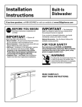
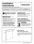
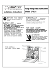
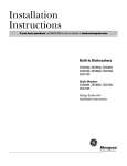
GE Monogram® Installation Instructions with Optional Trim Kit Installation Instructions Built-In Dishwashers Models ZBD5600 ZBD5700 ZBD5900 Before you begin - Read these instructions completely and carefully. IMPORTANT - Save these instructions for local inspector’s use. IMPORTANT - OBSERVE ALL GOVERNING CODES AND ORDINANCES. Note to Installer - Be sure to leave these instructions with the Consumer. Note to Consumer - Keep these instructions with your Use and Care Book for future reference. This appliance must be properly grounded. See “Power Supply”, page 8. CAUTION WARNING CAUTION AVERTISSEMENT Cet appareil doit être correctement mis à la terre. Consulter « Alimentation électrique » page 8. If the dishwasher is a new installation, most of the work must be done before the dishwasher is moved into place. If this dishwasher is replacing another dishwasher, the connections must be checked for compatibility and replaced as necessary. If you have a question concerning the installation of this product, call the GE Answer Center® Consumer Information Service at 800.626.2000, 24 hours a day, 7 days a week. If you received a damaged dishwasher, you should immediately contact your dealer or builder. CAUTION CAUTION • This dishwasher must be installed to allow for future removal from the enclosure if service is required. • Use this appliance only for its intended purpose. CAUTION ATTENTION For Monogram local service in your area, 1-800-444-1845. For Monogram service in Canada, 1-888-880-3030. For Monogram Parts and Accessories, call 1-800-626-2002. Contents Installation of this dishwasher requires basic mechanical and electrical skills. Proper installation is the responsibility of the installer. Product failure due to improper installation is not covered under the GE Appliance Warranty. See the Use & Care Guide for warranty information. • Ce lave-vaisselle doit être installé de façon à permettre la sortie ultérieure de l’enceinte en cas d’intervention. • Il ne faut utiliser cet appareil que pour l’usage pour lequel il a été construit. Design Information Models Available ............................................. Product Dimensions ....................................... Advance Planning .......................................... Standard Installation in 24" Deep Cabinets . Optional Trim Kits ......................................... Corner Installation......................................... 3 3 3 4 4 4 Installation Preparation Parts Supplied ................................................. Materials You Will Need ................................ Tools You Will Need ....................................... Prepare the Opening ..................................... Water Supply ................................................... Power Supply .................................................. Prepare Drain Plumbing ............................... 5 6 6 7 7 8 9 Installation Step 1 Remove Wood Base .......................... 10 Step 2 Install Leveling Legs and Toekick Brackets ................................. 10 Step 3 Install Water Inlet Fittings ................ 11 Step 4 Install Power Cord ............................ 11 Step 5 Level the Dishwasher ........................ 12 Step 6 Slide Dishwasher into Opening ....... 12 Step 7 Connect Water Line ......................... 12 Step 8 Install Drain Line .............................. 13 Step 9 Connect Electrical ............................ 13 Step 10 Secure Dishwasher to Countertop or Cabinetry ........................... 14 Step 11 Install Toekick Assembly ................ 15 Step 12 Install Side Filler Strips .................. 15 Panel Kits ZPF25 Door Panel Kit .................................. 16 1/4" Thick Custom Door Panel ZPF75 Door Panel Kit .................................. 19 3/4" Thick Custom Door Panel 2 Design Information Stainless Steel Interior Dishwashers Models Available ZBD5600 WW, ZBD5700 WW White Dishwashers ZBD5600 BB, ZBD5700 BB Black Dishwashers ZBD5900 SS Stainless Steel Dishwasher These dishwashers are designed for versatility, adaptable to virtually any installation. These models have a full length trimless door without the traditional access panel. The black and white models can be customized with decorative panels of wood or other material. Product Dimensions A – 34” Min. adjustable to 35” max. B – 23-5/8” C – 23-1/2” total depth D – 4” max., 2-7/8” min. E – 5” escutcheon height F – Adjustable, to 3-1/4” G – 25-1/4” from cabinets face (depending on depth of cabinets) C G B E A Toekick F Advance Planning • The black and white models may be covered with custom decorative door panels of wood or other materials to match cabinetry. See “Optional Trim Kits,” page 4. • The stainless steel model does not accept custom panels. • A custom toekick can be installed to match cabinet toekick material. A continuous toekick may be installed to form an unbroken line at floor level. – A continuous toekick should be installed in such a manner that it can be removed if service is required. D • Tub flange trim is supplied to conceal any slight gap between the dishwasher and adjacent cabinetry. • These dishwashers may be installed beneath countertops of stone or other materials that will not accept screws. No trim kit required. See “Secure dishwasher to countertop or adjacent cabinetry”, page 14. 3 Design Information Stainless Steel Interior Dishwashers Standard installation in 24” deep cabinets • Install in standard 24” deep cabinets: – The dishwasher door will be flush with the front face of adjacent cabinetry. • With a 3/4” thick custom door panel in place, the exterior is trimless and fits flush to adjacent cabinetry. Optional Trim Kits • ZPF25W, white or ZPF25B, black custom panel kit – Provides for the installation of a 1/4” thick custom door panel. See page 16 for installation instructions. • ZPF75W, white or ZPF75B, black custom panel kit – Provides for a trimless appearance using a 3/4” thick custom door panel. See page 19 for installation instructions. Corner installation • For a corner installation, allow 2” clearance between dishwasher and adjacent cabinet or wall. • Dishwasher must be placed no more than 10 feet from sink for proper drainage. Cabinet Depth 24" Cabinet Resting Against Wall 4 Installation Information Stainless Steel Interior Dishwashers Parts Supplied Remove the hardware accessory bag and other parts from inside or taped to the outside of the dishwasher. Check contents against drawings to insure that all parts are included. ■ 2 toekick slides ■ 2 toekick support brackets ■ 2 side trim pieces ■ 2-piece toekick ■ 16 Screws (see illustration) ■ 2 leveling legs ■ Junction box Screw A (2) Countertop Mounting Screws Screw B (4) Side Trim Screws 2 Leveling Legs Screw C (4) Toekick Bracket Screws Left and Right Side Toekick Support Brackets Screw D (2) Cabinet Mounting Screws Screw F Screw E (2) Toekick (2) Junction Box Screws Slide ScrewsColor Matched Front Toekick Panel Left and Right Side Toekick Slides Inner Toekick Panel 2 Piece Toekick Junction Box 2 Side Trim Pieces 5 Installation Preparation Stainless Steel Interior Dishwasher Materials You Will Need: (not supplied) ■ 90° elbow (3/8" NPT external thread on one end and opposite end to fit hot water supply line) ■ Thread seal tape ■ UL listed wire nuts (3) For new installations only: ■ Air gap for drain hose, if required ■ Waste tee for house plumbing, if applicable ■ Electrical cable or power cord, if applicable ■ Screw type hose clamps ■ Strain relief for electrical connection ■ Hand shut-off valve (recommended) ■ Water line 3/8" O.D. min. copper or 1/2" O.D. min plastic. Air Gap Wire Nuts Electrical Cable or Power Cord 90° Elbow Screw Type Clamps Thread Seal Tape Hot Water Line Shut-Off Valve Waste Tee Strain Relief Tools you Will Need: (Not Supplied) ■ ■ ■ ■ ■ ■ ■ ■ Phillips head and flat blade screwdrivers Adjustable wrench (6") 3/8", 5/16" and 1/4" nut drivers Level Carpenter’s square Measuring tape Safety Glasses Safety glasses Coupler Flat Blade Screwdriver Nut Driver Phillips Head Screwdriver Flashlight For new installation only: ■ Tubing cutter ■ Drill and appropriate bits ■ Hole saw set Hole Saw Set Adjustable Wrench Tubing Cutter Flashlight Measuring Tape Drill and Bits Level Square 6 Installation Preparation Stainless Steel Interior Dishwasher Prepare the Opening • The rough cabinet opening must be 24” min. deep, 23-5/8” min. to 24” max. wide. The opening height should be 34” min. and 35” max. • The opening should be free of extraneous pipes and wires. 34" to 35" Underside of Countertop to Floor This Wall Area must be Free of Pipes or Wires 1-3/4" 24" Min. 6" 23-5/8" Min. 24" Max Water Supply • Hot water line may enter from either side, from the rear, or from the floor within the shaded area shown. • Turn off water supply. • Cut a hole approximately 1-1/2” in diamRight Side Entry eter to admit water line. Access hole must Shut-off Valve 1-1/2" Approx. 40" Dia. be round and smooth. 1-3/4" from Wall Hole • Install a hand shut-off valve in the supply line in an accessible location, such as under Hot the sink. (The shut-off valve is optional, but 6" recommended and may be required by local codes.) Left Side Entry • Install the hot water line, using no less than Approx. 30" 3/8” O.D. copper tubing or 1/2” O.D. Cabinet Face 2" from Floor from Wall plastic tubing. • The water line must be long enough to form a smooth natural loop with no sharp bends or kinks between the cutout entry and fill valve location, centered at the front of the dishwasher. • Adjust the water heater to deliver 120°F min. water temperature. • The water pressure of the hot water supply line must be 20 to 120 psi. • Before connecting, flush water line to clean out debris. 7 Installation Preparation Stainless Steel Interior Dishwashers Power Supply WARNING FOR PERSONAL SAFETY: REMOVE HOUSE FUSE OR OPEN CIRCUIT BREAKER BEFORE BEGINNING INSTALLATION. DO NOT USE AN EXTENSION CORD OR ADAPTER PLUG WITH THIS APPLIANCE. FOLLOW NATIONAL ELECTRICAL CODES OR PREVAILING LOCAL CODES AND ORDINANCES. Alternate Receptacle Location 18" 18" 6" Receptacle Location Area 1-1/2" Dia. Hole (Max.) AVERTISSEMENT 2" SÉCURITÉ IL FAUT ENLEVER LE FUSIBLE DE LA MAISON OU OUVRIR LE DISJONCTEUR AVANT DE COMMENCER L’INSTALLATION. IL NE FAUT PAS UTILISER DE RALLONGE NI D’ADAPTATEUR DE FICHE AVEC CET APPAREIL. IL FAUT RESPECTER TOUS LES CODES D’ÉLECTRICITÉ NATIONAUX OU LES CODES ET RÈGLEMENTS LOCAUX EN VIGUEUR. Electrical Requirements: These dishwashers must be supplied with a 120 volt, 60 Hz power supply with an individual, properly grounded branch circuit, protected by a 15 or 20 amp fuse or circuit breaker or time delay fuse. • Wiring must be 2 wire with ground. • If electrical supply does not meet the above requirements, call a licensed electrician before proceeding. Grounding Instructions: This appliance must be either connected to a grounded-metal permanent wiring system, or an equipment-grounding conductor must be run with the circuit conductors and be connected to the equipment-grounding terminal or lead on the appliance. WARNING THE IMPROPER CONNECTION OF THE EQUIPMENT - GROUNDING CONDUCTOR CAN RESULT IN A RISK OF ELECTRIC SHOCK. CHECK WITH A QUALIFIED ELECTRICIAN OR SERVICE REPRESENTATIVE IF YOU ARE IN DOUBT WHETHER THE APPLIANCE IS PROPERLY GROUNDED. 3" 2" from Cabinet 6" 24" from Wall Ground Black White Cabinet Preparation & Wiring: • Wiring may enter from either side, the rear, or from the floor within the shaded area shown. • Cut hole 1-1/2” max. diameter within the shaded area to admit the electrical cable or power cord. The hole must be free of sharp edges. If the cabinet wall partition is metal, the edge of the hole must be covered with a rubber protector. Electrical Connections: The electrical connection is on the right side of the dishwasher. • For cable direct connections, the cable must be routed as illustrated. The cable must extend forward a minimum of 24” from the rear wall. • For power cord connections, install a 3-prong type receptacle in the rear wall of sink cabinet next to the dishwasher. Install the receptable at least 6” and not more than 18” from the dishwasher opening. The receptacle should be at least 6” and not more than 18” off the floor. • Allow approximately 3” between cable and adjacent cabinetry. AVERTISSEMENT LE MAUVAIS BRANCHEMENT DU CONNECTEUR DE MISE À LA TERRE DE L’ÉQUIPEMENT PEUT CAUSER UN RISQUE D’ÉLECTROCUTION. EN CAS DE DOUTE SUR LA MISE À LA TERRE DE L’APPAREIL, CONSULTER UN ÉLECTRICIEN QUALIFIÉ OU UN PRÉPOSÉ DE SERVICE. 8 Installation Preparation Stainless Steel Interior Dishwasher Prepare drain plumbing • Follow local codes and ordinances. • Dishwasher drain hose must not exceed 10 feet in length for proper drainage. – The dishwasher is supplied with a 3/4” I.D. drain hose, 78” long. Add up to 42” length to the factory supplied hose if necessary. • Dishwasher must be connected to waste line with an air gap (not supplied) or 30” minimum, high drain loop (depending on local codes and ordinances) to prevent back flow into the dishwasher. • An air gap must be used if waste tee or disposer connection is less than 12” above floor to prevent siphoning. • Install waste tee or disposer and air gap according to the manufacturer’s instructions. • Cut a hole in cabinet wall, approximately 1-1/2” in diameter for drain hose. • Install drain hose hook to underside of countertop. CAUTION CAUTION Method 1 – Air Gap with Waste Tee or Disposer Use this method when waste tee or disposer connection is less than 12” above the floor. Waste Tee Installation Disposer Installation Method 2 – High Drain Loop with Waste Tee or Disposer Use this method when high drain loop is at least 30” above the floor. 30" 12" Min. Min. Waste Tee Installation 30" Min. 18" Min. Disposer Installation An air gap MUST BE USED if the drain hose is connected to waste tee or disposer lower than 12” above the floor level. Failure to provide the proper drain connection height, 12", with air gap or 30” minimum high drain loop will result in improper draining of the dishwasher which may cause damage. CAUTION ATTENTION IL DOIT Y AVOIR un dispositif anti-retour si le tuyau de vidange est branché à un té d’égout ou à un broyeur d’ordures qui est à moins de 30 cm (12 po) au-dessus du sol. Si le tuyau d’égout n’est pas branché à une bonne hauteur, au moins 30 cm (12 po), avec un dispositif anti-retour, ou si la boucle d’égout haute n’est pas à une hauteur d’au moins 75 cm (30 po), le lave-vaisselle se vidange mal, ce qui peut causer des dégâts. 9 Installation Stainless Steel Interior Dishwasher Install Custom Door Panel • If you intend to install custom door panels, refer to installation instructions provided in this booklet. The panels should be in place before installing the dishwasher. Step 1 Remove wood base Cut the shipping carton and use it as a pad under the dishwasher. This will protect the finished floor in the kitchen. • Lay the dishwasher on its back. • Remove the 4 screws holding the dishwasher to the wood base. Discard screws. • Retain wood base. • Insure that the floor of the cutout is the same level or higher than the rest of the room. If the kitchen floor is tile, it may be elevated above the floor of the installation cutout. Pieces of the wood base may be placed into the cutout floor to make it level or higher than with the kitchen floor. This will allow for easy removal for any future service. Step 2 Install leveling legs & toekick brackets 22-7/16" • Un-wrap the drain hose and pull to the rear of the dishwasher. Take care not to kink or crush the hose. • Install toekick support brackets on the left and right sides of the mounting brackets using 2 screws each. See illustration for correct orientation. • Install the front leveling legs provided in the parts package. The legs should be at least 2” from the bottom edge of the mounting bracket. • Adjust leveling legs to installation height. Tighten leveling leg locking nuts on the rear. 2" Min. Mounting Bracket Screw C Toekick Support Bracket 10 Installation Stainless Steel Interior Dishwasher Step 3 Install Water Inlet Fittings • Install the 90° elbow onto the water inlet. Use thread sealing tape or pipe thread compound. • The 90° elbow should face the left or right side, depending on water line routing. Step 4 Install power cord • Install strain relief onto junction box and tighten against incoming wires. • Strip 1/2” insulation from end of power cord wires. • Connect incoming wires to dishwasher wires using wire nuts of appropriate size. • Connect the white to white, black to black and incoming ground to green wire. • Push all wires into the junction box and secure cover with screws onto dishwasher frame. (If used) Skip this step If dishwasher will be wired direct. Note: The power cord and connections must comply with the National Electrical Code, Section 422 and/or local codes and ordinances. IMPORTANT: The power cord must be no longer than 6 ft from the junction box to the plug. DO NOT PLUG IN POWER CORD AT THIS TIME. Screw F 11 Installation Stainless Steel Interior Dishwasher Step 5 Level the Dishwasher • Carefully upright the dishwasher, taking care not to bend the leveling legs. Make sure the leveling leg locking nuts are secure. • Check to be sure the dishwasher is level and at the cutout height. Step 6 Slide Dishwasher Into Opening • Insert drain hose into the hole previously drilled in the cabinet wall. • Slide the dishwasher into the opening a few inches at a time. • As you proceed, pull the drain hose through the cabinet wall under the sink. • If a power cord is used, guide the end through a separate hole. • Check to be sure there is no interference with waterline or house wiring. Step 7 Connect Water Line • The water supply line should be flushed to clear any foreign material before connecting to the dishwasher. • Make sure there are no sharp bends or kinks which could restrict the water flow. 12 Installation Stainless Steel Interior Dishwasher Step 8 Install Drain Line • Follow all local codes and ordinances. Drain Line Preparation • The dishwasher is supplied with a 78” long corrugated drain hose. • If the location requires a longer drain hose, add up to 42” length to the supplied hose. Use 3/4” inside diameter hose and thin wall copper coupler to join the hose ends. Note: Total drain hose length must not exceed 10 feet for proper drain operation. Drain Line Installation • Connect drain line to air gap, waste tee or disposer using either method 1 or 2 as previously determined. • Secure connection using appropriate clamps (not supplied). • Make sure drain hose is not kinked. Note: Remove drain plug before connecting to disposer. Dishwasher cannot drain if plug is left in place. Step 9 Connect Electrical (For direct connection to house wiring) WARNING Method 1 – Air Gap with Waste Tee or Disposer Waste Tee Installation Disposer Installation Method 2 – High Drain Loop with Waste Tee or Disposer Fasten to underside of countertop 30" 12" Min. Min. Waste Tee Installation Fasten to underside of countertop 30" 12" Min. Min. Disposer Installation If house wiring is not 2-wire with a ground wire, a ground must be provided by the installer. When house wiring is aluminum, be sure to use U.L. listed anti-oxidant compound and aluminumto-copper connectors. AVERTISSEMENT Si le circuit de la maison n’a pas deux fils, plus un fil de terre, l’installateur doit installer un fil de terre. Quand les fils de la maison sont en aluminium, il faut prendre soin d’utiliser une pâte anti-oxydante et des connecteurs aluminium à cuivre sur la liste UL. Screw F Verify that power is turned off at the source. • Install a strain relief onto the junction box and tighten against the incoming wires. • Strip 1/2” insulation from end of incoming wires. • Use wire nuts of appropriate size and connect white to white, black to black and incoming ground to green wire. • Push all wires into the junction box and place on dishwasher frame. Secure with screws “F”. 13 Installation Stainless Steel Interior Dishwasher Step 10 Secure Dishwasher to Countertop or Cabinetry To maintain position and alignment the dishwasher must be secured to the countertop or to adjacent cabinetry. If countertop is of stone or other hard material, secure the dishwasher to adjacent cabinets. • Check to be sure that dishwasher is adjusted to correct height and is centered in the cutout. • Open and close dishwasher door to insure proper operation of the door. If there is any binding or rubbing, readjust leveling legs. Secure dishwasher to countertop: • Drill pilot holes through the mounting bracket and into the underside of the countertop. Install 2 screws “A” provided. Note: Take special care to ensure countermount screws are driven flush so they do not damage top of door, when door is closed. Screw A Secure dishwasher to adjacent cabinets: • Remove plastic plug button on the inside of the dishwasher frame. One on each side. • Drill pilot holes through the holes and into the adjacent cabinets. Install 2 screws “D” provided. • Replace plastic plug buttons. Screw D 14 Installation Stainless Steel Interior Dishwasher Step 11 Install Toekick Assembly • Install toekick slides to toekick support brackets. Use slide stamped “L” on left and “R” on right side. • Align front and inner toekicks, matching screw holes. • Align toekick to second screw hole in toekick slide as illustrated. • Install color matched screws “E” through the front of the toekick and into the toekick slides. Do not tighten screws. • Carefully, slide assembly back until it is aligned with adjacent cabinetry toekick. • Adjust the height of the panel by loosening screws and sliding the front panel down, even with the floor. • Carefully, hold the door and open fully. Ensure that door does not strike top of toekick. • Adjust toekick height if necessary. • Tighten screws. Front Toekick Panel Inner Toekick Left Side Toekick Slide Slide toekick out Screw E Step 12 Install Side Trim Attachment Screws Pull tab while Pushing toekick in • Side trim filler strips are packed with this dishwasher. If the cabinet cutout is wider than the dishwasher, install the filler strips on both sides of the dishwasher to cover gaps. • Open the door fully. • Place side trim against dishwasher tub and install 2 screws, loosely on each side. • Adjust trim to correct width. Tighten screws. Side Trim Screw B 15 ZPF25 Custom Door Panel Kit 1/4" Thick Custom Door Panel Note: It is best that 2 people perform this installation. ZPF25B, Black trim ZPF25W, White trim The ZPF25 trim kit provides support for 1/4” thick custom door panel. Tools and Materials required • Phillips screwdriver • Gloves to protect against sharp edges. WARNING Kit Contents Note: Maximum custom panel weight is 10 pounds. To prevent electrical shock, disconnect electrical power supply to dishwasher before changing panels. Do not operate dishwasher when door assembly is removed. • Metal door • 8 wood screws • 6 “C” clips • Door Trim • 2 Door Springs AVERTISSEMENT Pour éviter les électrocutions, il faut débrancher l’alimentation électrique du lave-vaisselle avant de changer les panneaux. Il ne faut pas faire fonctionner le lavevaisselle quand la porte est déposée. (8) Screws Metal Door Door Trim “C” Clips 2 Door Springs Step 1 Cut 1/4” Thick Custom Panel to Size • Cut door panel to the dimensions shown. • The bottom left and right corners should be cut at 1/4” radius. See illustration. Note: The trim will conceal the cut edges of the panels. 1/4" Radius Cut 1/4" Thick Door Panel 25-1/2" 23-1/8" 16 ZPF25 Custom Door Panel Kit 1/4" Thick Custom Door Panel Step 2 Remove Existing Metal Door • Open the door fully. Caution: One person should hold the door while the other backs out screws to prevent the metal door from falling. • Remove 6 screws on the inside the inner door frame. Retain screws. • Remove the 2 screws with o-rings located in the bottom center of the inner door. Retain screws and o-rings. • Remove the outer door. • Remove the 2 screws holding the center door bracket to metal door. • Retain bracket and insulation. • Discard metal door. Step 3 Assemble Panel to Door • Place the supplied metal door on a flat surface. • Place the custom panel on top of the metal door. • Place supplied trim over the custom panel. • Press trim to panel and install the color matched screws provided. Install 3 screws on each side and 2 screws on the bottom. Decorative Panel Door Trim Door Panel Step 4 Install Door Center Bracket • Turn the assembled door over with appearance side down. • Install center door bracket onto door using original screws. • Place insulation around support bracket. Insulation Install Screws 17 ZPF25 Custom Door Panel Kit 1/4" Thick Custom Door Panel Step 5 Install Assembled Door onto Dishwasher • Locate the “C” clips in the parts package. Place one clip, flat side up, over each of the screw holes, 3 on each side of the door. Note: One person should hold the door while the other installs screws to prevent the door assembly from falling. • Hold the assembled door to dishwasher inner door and slide up against control panel. Control panel has posts that should engage the 2 holes in the top of the metal door. • Install the original center screws and o-rings. Note: Center screws and o-rings must be securely fastened to prevent future leaks. “C” Clips • Install original screws to sides of inner door frame, 3 each side. Step 6 Install Door Springs The additional weight of the custom panel may require that the heavy door springs be installed. Test Door Balance • With one hand under the door, slowly open the door fully. • Open and close the door to check for proper balance. Correct door balance should prevent the door from raising by itself from a full open position and prevent the door from falling heavily. • If the door falls heavily, damage will occur from repeated use. • Install one or both new springs provided. Push Rod Guide Install New Springs: • Close and latch the dishwasher door. • Locate door spring on left side of dishwasher. • Disengage the push rod guide by pushing down on the guide and slowly pulling the guide out of the mounting position. • Carefully release the tension on the spring and remove the push rod guide from the rod. • Remove the spring and replace with the spring that has a yellow marking. • Reassemble the push rod guide into the original position. • Test door balance. • Install right side spring if needed. 18 ZPF75 Custom Panel Kit 3/4" Thick Custom Door Panel ZPF75B, Black ZPF75W, White Note: It is best that 2 people perform this installation. The ZPF75 provides for the installation of 1/2” to 3/4” thick custom door panel. Tools and Materials required • Phillips screwdriver • Gloves to protect against sharp edges • Nut driver WARNING Kit Contents Note: Maximum custom panel weight is 10 pounds. AVERTISSEMENT To prevent electrical shock, disconnect electrical power supply to dishwasher before changing panels. Do not operate dishwasher when door assembly is removed. Pour éviter les électrocutions, il faut débrancher l’alimentation électrique du lave-vaisselle avant de changer les panneaux. Il ne faut pas faire fonctionner le lavevaisselle quand la porte est déposée. • Metal door • Support bracket • Label • 18 Screws • 2 Door springs Metal Door Screw Y Screw X (6) Not Used (10) Wood Screws Step 1: Determine Custom Panel Sizes Screw Z (2) Support Bracket Screws Door Springs Support Bracket The custom panel should be constructed in the same manner as cabinet doors. All edges can be seen and must be finished for the best appearance. Custom Panel Size Countertop Cabinets Dim. A* Floor Bottom of 3/4" Max. Adjacent Cabinetry Top 3/4" Thick Door Panel *Height 23-1/8" • Measure dimension A, from underside of countertop to bottom of adjacent cabinets. – Subtract 5-1/8". Control panel height is 5". Allow 1/8" for gap between bottom of countertop and top of control panel. – Add 1/4". The custom panel will slide up, behind control panel. *Height is equal to A minus 5-1/8" plus 1/4" EXAMPLE: *Height = 30-1/2" minus 5-1/8" plus 1/4" is equal to 25-5/8". 19 ZPF75 Custom Panel Kit 3/4" Thick Custom Door Panel Step 2 Remove Existing Metal Door Step 3 Install Door Center Bracket • Open the door fully. Caution: One person should hold the door while the other backs out screws to prevent the metal door from falling. • Remove 6 screws on the inside of the frame. Retain screws. • Remove the 2 screws with o-rings located in the bottom center of the door. Retain screws and o-rings. • Remove the door. • Remove insulation and foam inserts, discard metal door. 2 “O” Rings 2 Foam Inserts • Install new center door bracket onto door using screws “Z”. • Place insulation around support bracket. Support Bracket 2- Depressions Flat Face Screw Z Metal Integrated Door Step 4 Assemble Custom Panel • Lay custom panel on a flat surface, appearance side down. • Place the new metal door panel onto the back of the custom door panel. Align sides and top edges. • Drill 1/8” pilot holes, 3/8” deep, through the metal panel and into the custom panel, 3 each side. • Secure custom panel to metal door with 3 screws “X” on each side. • Drill 1/4” pilot holes through the top return flange, approximately 1/4” deep. Drill 1/8" Holes (3 Each Side) Screw X Drill 1/4" Holes Custom Panel 20 ZPF75 Custom Panel Kit 3/4" Thick Custom Door Panel Step 5 Install Assembled Door onto Dishwasher Note: One person should hold the door while the other installs screws to prevent the door assembly from falling. • Check to be sure that foam inserts are in place. • Hold the assembled door to dishwasher inner door and slide up against control panel. The control panel has posts that should engage the 2 holes in the top of the metal panel. 2 “O” Rings Foam Insert Foam Insert • Install the original center screws and o-rings. Moisture Strip Control Panel Post Holes Note: Center screws and o-rings must be securely fastened to prevent leaks. • Install original screws to sides of inner door frame, 3 each side. Step 6 Install Door Springs The additional weight of the custom panel may require that the heavy door springs be installed. Test Door Balance • With one hand under the door, slowly open the door fully. • Open and close the door to check for proper balance. Correct door balance should prevent the door from raising by itself from a full open position and prevent the door from falling heavily. • If the door falls heavily, damage will occur from repeated use. • Install one or both new springs provided. Push Rod Guide Install New Springs: • Close and latch the dishwasher door. • Locate door spring on left side of dishwasher. • Disengage the push rod guide by pushing down on the guide and slowly pulling the guide out of the mounting position. • Carefully release the tension on the spring and remove the push rod guide from the rod. • Remove the spring and replace with the spring that has a yellow marking. • Reassemble the push rod guide into the original position. • Test door balance. • Install right side spring if needed. 21 ZPF75 Custom Panel Kit 3/4" Thick Custom Door Panel Step 7 Install Custom Toekick • Slip toekick slides into guides by pulling out the metal tabs. • Hold custom panel against toekick slides and mark screw hole locations. • Remove toekick and drill 1/8" pilot holes. • Remove toekick slides and secure panel to slides with 2 screws each. Use screws “X”. If panels are 1/2" thick, use caution when driving these screws. • Insert the assembled toekick into the support brackets by pulling out the metal tabs. • Carefully, slide assembly back until it is aligned with adjacent cabinetry toekick. • See product installation instructions to reinstall the dishwasher. • Carefully, hold the door and open fully. Insure that door does not strike top of Screw X toekick. Pull Tab While Pushing toekick in 22 Notes Stainless Steel Interior Dishwasher 23 NOTE: While performing installations described in this book, safety glasses or goggles should be worn. To obtain specific information concerning any Monogram product or service, call GE Answer Center® consumer information service at 800.626.2000—any time, day or night. For Monogram local ser vice in your area, call 1-800-444-1845. In Canada call, 1-888-880-3030. ® Monogram. General Electric Company Louisville, KY 40225 NOTE: Product improvement is a continuing endeavor at General Electric. Therefore, materials, appearance and specifications are subject to change without notice. Pub. No. 49-5860-1 Printed in USA 1999 GE Appliances (N.D. 458) 9/99 Part Number: C82 0017x Issue A