1
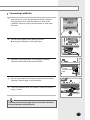
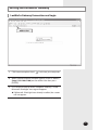
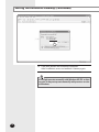
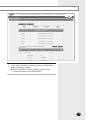
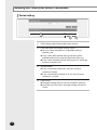
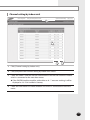
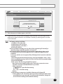
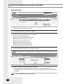
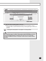
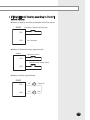
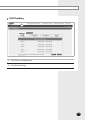
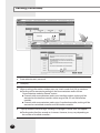
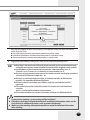
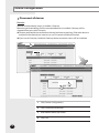
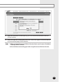
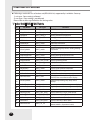
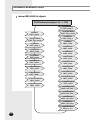
LonWorks Gateway MIM-B18 Air Conditioner installation manual imagine the possibilities Thank you for purchasing this Samsung product. E DB98-32769A(1) Safety Precautions This installation manual describes how to install the LonWorks Gateway. For installation of other optional accessories, refer to the appropriate installation manual. WARNING CAUTION R ead carefully this installation manual before installation and check if the LonWorks Gateway is installed correctly after installation. Do not attempt to install or repair this LonWorks Gateway by yourself. T his LonWorks Gateway contains no user-serviceable parts. Always consult authorized service personnel for repairs. When moving, consult authorized service personnel for disconnection and installation of the LonWorks Gateway. E nsure that the wall is strong enough to support the weight of the LonWorks Gateway. M ust install the LonWorks Gateway with rated power supply. T he LonWorks Gateway must be installed according to the national electrical rules by an installation specialist. If you wish to uninstall the LonWorks Gateway, consult an authorized installation center. Do not use inflammable gases near the LonWorks Gateway. D o not install the LonWorks Gateway in a location where it will come into contact with combustible gases, machine oil, sulphide gas, etc. A void locations where acid/alkali solution or special spray is used. C hoose a location that is dry and sunny, but not exposed to direct sunlight. Suitable temperature is between 0°C(32°F) and 39°C(102.2°F). Do not spill water into the LonWorks Gateway. D o not apply tensile strength to the cable to avoid cable damage. D o not press the buttons with a sharp object. D o not connect the power cable to the control terminal. If the LonWorks Gateway is installed in a hospital or other special places, it should not affect other electronic devices. LonWorks, LON and Lontalk are registered trademarks of Echelon Corporation. E-2 Contents Safety Precautions ........................................................... 2 Before Installing the LonWorks Gateway .......................... 4 Accessories ...................................................................... 5 Viewing the Parts ............................................................. 6 Product Dimensions ......................................................... 8 System Architecture ......................................................... 9 Compatible Devices ........................................................ Installing the LonWorks Gateway .................................. Setting the LonWorks Gateway ...................................... Reading EHP Watt-hour Meter . .................................... System Setting Initialization ........................................... System Environment Setting ........................................... Tracking . ...................................................................... Device Configuration ..................................................... Overview for Function ................................................... Network Parameter Chart ............................................. Message Definition ........................................................ 10 12 21 26 31 32 40 46 52 54 56 E-3 Before Installing the LonWorks Gateway Checks before installation 1 LonWorks Gateway IP A public IP is needed to access the LonWorks Gateway over the internet. (One public IP is needed for each LonWorks Gateway) A private IP may be used if the LonWorks Gateway need not be accessed over the internet. 2 Network related equipments 3 Installation connection wire The LAN cable and the communication cables from centralized controllers/interface modules must be installed in such a way that the wires can be connected to the LonWorks Gateway with ease. Note E-4 T he LonWorks Gateway is a server and supports static IP. To access the LonWorks Gateway through the internet or with BMS System, the LonWorks Gateway address, which is the IP address, must be known. A static IP service from an internet service provider must be used if xDSL (ADSL, VDSL) is being used for internet connection. (Static IP costs more than dynamic IP.) Accessories Make sure you have each item. Supplied items may vary depending on your country or service provider. Item LonWorks Gateway Adapter Power cable M4 x16 Screw Quantity 1 1 1 6 User’s manual Installation manual Cable tie 1 1 1 Shape The LonWorks Gateway must be installed by a trained installer. Ensure the main power is turned off before installing the LonWorks Gateway. Be sure to use adapter and power cable we provide. The power cable and the communication cable must be installed according to the national electrical wiring regulations. E-5 Viewing the Parts Main Parts LonWorks Gateway Exterior LCD Display Shows current time and IP address. Various messages will be displayed depending on button input. LCD operation button There are 4 buttons(Menu, (Down), (Up), Set) and you can access to menu and move, check the menu. LED Indicator Check 15 LED status such as Power, CPU-Alive, Ethernet-Linked/Active, COM1~4-TX/RX, Lon ACK, Lon SVC and Check. LonWorks Gateway Bottom cover Unfasten 2 screws on the bottom and separate the bottom cover from LonWorks Gateway. Then check cable connection part. LED Indicator Item Power Name Status Power indicator Turns blue when the power is supplied. CPU Alive CPU operation indicator Blinks in orange with 1 second intervals during normal operation. Ethernet– Linked Internet connection indicator Turns green during normal connection. Ethernet– Active Internet data transmission/reception indicator Blinks in orange during normal transmission/reception. COM1~4 – TX Channel 1~4 Centralized controller/Interface Blinks in green during normal module Data transmission Indicator transmission. COM1~4 – RX Channel 1~4 Centralized controller/Interface Blinks in green during normal reception. module Data reception Indicator Lon ACK LonWorks data reception indicator Blinks in green during normal reception. Lon SVC LonWorks device status indicator Blinks in green during un-configured. - Needs commission by integration tool (Ex. LonMaker) Check E-6 Indoor/Outdoor unit/Communication check Turns green when notice occurs. Indicator LonWorks Gateway Cable Connection Part DI Terminal1 Power Terminal Reset Button RS485 Communication Terminal DO Terminal3 DO Terminal4 Lon Terminal DI Terminal2 Serial Terminal SD Card Socket Name Cable tie groove Reserved Ethernet Terminal Description DI Terminal1 Digital Input connection terminal, Channel1~Channel5 DI Terminal2 Digital Input connection terminal, Channel6~Channel10 DO Terminal3 Digital Output connection terminal, Channel1~Channel5 DO Terminal4 Digital Output connection terminal, Channel6~Channel8 Lon Terminal Terminal Block for LonWorks communication (TP/FT-10) Reset Button Reset LonWorks Gateway Power Terminal Connect LonWorks Gateway adapter Serial Terminal Service agent checks LonWorks Gateway error status using this terminal SD card socket Sub memory (for program update and set information saving) socket RS485 Communication Terminal Connect for RS485 communication with devices such as centralized controller/Interface module -COM1 ~ COM5 Ethernet Terminal Connect LAN cable Cable tie groove Groove for arranging cables E-7 Viewing the Parts (Continued) Main Parts LonWorks Gateway Interior Display Board 20-pin Cable LonWorks Board 2-pin Cable 10-pin Cable Main Board 40-pin Cable Sub Board Note If you need external circuit configuration, consult with the manufacturer. Product Dimensions 64.80 255 240 E-8 (Unit : mm) System Architecture BMS system TP/FT-10 BMS Engineering SAMSUNG Engineering LonWorks Gateway Centralized controller Interface module Interface module Interface module Connecting centralized controller and LonWorks Gateway ( type) - You can control up to 16 centralized controllers and 128 indoor units using LonWorks Gateway. Connecting interface module and LonWorks Gateway( type) - You can control up to 80 interface modules and 128 indoor units using LonWorks Gateway. *MAX.16 interface module can be connected to each of the RS485 communication channels of the LonWorks Gateway. - The more interface modules are connected, the longer time takes for tracking. W hen connecting centralized controller and interface module to the LonWorks Gateway of same communication channel, only one of them will communicate according to the communication channel mode setting of [System Settings]-[Tracking]. Therefore, do not connect the centralized controller and interface module to the same communication channel. If you set the communication channel mode as interface module, virtual centralized controller address will be assigned. E-9 Compatible Devices No Devices 1 Indoor Unit Outdoor Unit 2 Centralized Controller 3 SIM/PIM Model Note All System indoor/outdoor units such as: DVM, DVM PLUS, DVM PLUS II, DVM PLUS III, mini DVM, CAC Series - MCM-A202, MCM-A202A, MCM-A202B - MIM-B12/MIM-B16 Needed for EHP power distribution MIM-B04A (DVM, DVM PLUS, etc.) 4 5* Interface module MIM-B13 (DVM PLUS II, etc.) MIM-B13A (DVM PLUS II/ DVM PLUS III, etc.) MIM-B13B - RS485 comm. type Connect with SIM Needed for power distribution ( Please consult Samsung for compatible power meters) Pulse type Connect with PIM (Refer to PIM installation manual for the detailed specification of pulse type watt-hour meter.) Watt-hour Meter Products with ‘* ’ are not Samsung products and must be purchased separately. (Only selected power meters may be used for protocol compatibility issues.) Samsung is not responsible for BMS engineering which creates each device and objects. For further directions regarding on BMS engineering, consult with specialized BMS related vendor. E-10 Maximum Devices Attachable Devices Max. Note Indoor Unit 128 Tracking error occurs if exceeded Centralized Controller 16 Must not exceed 16 units Interface module 128 16 units per 1 channel, total 80 units are connectable when connecting interface module to LonWorks Gateway directly (128 units are connectable when using centralized controller) SIM/PIM 8 Up to 8 units are connectable Watt-hour Meter 64 8 units are connectable per 1 SIM/PIM E-11 Installing the LonWorks Gateway Installation plate E-12 1 Separate the installation plate on the rear side of LonWorks Gateway. 2 Fix the installation plate on the wall using 4 screws. 3 Hang the LonWorks Gateway on the groove which is on the top of the installation plate. 4 Fix the installation plate and LonWorks Gateway using 2 screws. 5 If you install LonWorks Gateway inside of the wall or wiring from the rear side is needed, use wiring groove on the bottom of LonWorks Gateway. wiring groove To prevent breakdown and damage of LonWorks Gateway, and for safe usage, it is recommended to install LonWorks Gateway on the wall. E-13 Installing the LonWorks Gateway (Continued) Connecting Centralized Controller 1 Unfasten the 2 screws on the bottom of the LonWorks Gateway front cover. Hold the bottom 2 sides of the LonWorks Gateway and push downwards to slide open the cover. 2 Connect the adapter to the power terminal. Arrange the adapter as the right figure. Adapter 3 Separate 1 terminal block from 5 terminal blocks which are attached to RS485 communication terminal. Then, connect centralized controller communication cable (C1, C2) to the terminal block.(C1A, C2B) 4 Connect LAN cable to the Ethernet terminal of LonWorks Gateway. Then arrange it using cable tie. 5 Fasten the bottom cover of LonWorks Gateway and fix it using 2 screws. Connect communication cable Cable tie LAN cable Maximum 16 centralized controllers can be connected to one LonWorks Gateway. E-14 Connecting Interface Module 1 Unfasten the 2 screws on the bottom of the LonWorks Gateway front cover. Hold the bottom 2 sides of the LonWorks Gateway and push downwards to slide open the cover. 2 Connect the adapter to the power terminal. Arrange the adapter as the right figure. Adapter 3 Separate 1 terminal block from 5 terminal blocks which are attached to RS485 communication terminal. Then, connect interface module communication cable(R1, R2) to the terminal block.(R1A, R2B) 4 Connect LAN cable to the Ethernet terminal of LonWorks Gateway. Then arrange it using cable tie. 5 Fasten the bottom cover of LonWorks Gateway and fix it using 2 screws. Connect communication cable Cable tie LAN cable Maximum 80 interface modules can be connected to one LonWorks Gateway. E-15 Installing the LonWorks Gateway (Continued) Connecting SIM 1 Unfasten the 2 screws on the bottom of the LonWorks Gateway front cover. Hold the bottom 2 sides of the LonWorks Gateway and push downwards to slide open the cover. 2 Connect the adapter to the power terminal. Arrange the adapter as the right figure. Adapter 3 Separate 1 terminal block from 5 terminal blocks which are attached to RS485 communication terminal. Then, connect SIM communication cable (C1, C2) to the terminal block. (C1A, C2B) 4 Connect LAN cable to the Ethernet terminal of LonWorks Gateway. Then arrange it using cable tie. 5 Fasten the bottom cover of LonWorks Gateway and fix it using 2 screws. Connect communication cable Cable tie LAN cable aximum 8 SIM units can be connected to one LonWorks M Gateway. E-16 Connecting LonWorks 1 Unfasten the 2 screws on the bottom of the LonWorks Gateway front cover. Hold the bottom 2 sides of the LonWorks Gateway and push downwards to slide open the cover. 2 Connect the adapter to the power terminal. Arrange the adapter as the right figure. Adapter 3 Separate Lon terminal block. Then, connect LonWorks communication cable to the terminal block. Connect communication cable 4 Connect LAN cable to the Ethernet terminal of LonWorks Gateway. Then arrange it using cable tie. 5 Fasten the bottom cover of LonWorks Gateway and fix it using 2 screws. Cable tie LAN cable L onWorks communication cable should use the cable which fits to the specification provided by Echelon. E-17 Installing the LonWorks Gateway (Continued) Commision Commision using Service Pin To activate the Service Pin, press and hold [SET] button for more than three seconds while time is displayed in the LCD Display window of the front side of LonWorks Gateway. Press and hold the [SET] button for more than 3 seconds. When you press Service Pin, Neuron ID will be sent and [SVC] LED of the front panel will be lit up for a second. You should correctly set up a network according to the installation and communication environment and set the data processing system in advance. This Gateway provides data for 128 indoor units. However, the connectable number of indoor units can be different according to the number of items, communication cycle or operating environment. Do not connect a device requiring urgent control in the same network. E-18 Control and Monitoring Item Functional classification by a device. The functions provided can be different according to the type of the connected device. Indoor ERV AHU Kit 1 nviOnOff ON/OFF command O O O 2 nviApplicMode Setting operating mode O X O 3 nviSetpoint Setting desirable temperature O X O X No NV Name Setting wind speed and direction O O 5 nviERVMode Setting ERV operation mode X O X 6 nviFilterReset Filter reset command O O O 7 nviUserLockout Setting the restriction of remote control use O O O 8 nviOccOpMode Setting cooling only mode / Setting heating only mode O X O 9 nviCoolTempLock 10 nviHeatTempLock 11 nvoSpaceTemp Setting the low temperature limit O X O Setting the high temperature limit O X O Display indoor temperature O X O 12 nvoApplicMode 13 nvoSetpoint Display operating mode O X O Display desire temperature O X O 14 nvoOnOff 15 nvoFanStatus Display ON/OFF status O O O Display wind speed and direction O O X 16 nvoERVMode 17 nvoErrorCode Display ERV operating mode X O X Display Error code O O O 18 nvoDeviceAlarm Remote control Lock, Filter Sign, Thermo ON/OFF, Error occurrence status display O O O 19 nvoOccOpMode Cooling only/Heating only setup status display O X O 20 nvoCoolTempLock Low temperature limit setting status display 21 nvoHeatTempLock High temperature limit setting status display O X O O X O 22 nvoUserLockout 23 nvoEnergyConp Display the restriction of remote control use O O O Display electricity usage (Time Period) O X X 24 nvoEnergyCon 25 nvoRuntimep Display electricity usage (Basic date) O X X Display used hours (Period) O X O 26 nvoRuntime Display used hours (Basic date) O X O 27 nvoDevListDesc The summary of device information (Model, Address, Operation Status) O O O 4 nviFanStatus Remarks E-19 Installing the LonWorks Gateway (Continued) Although the LonWorks Gateway can connect 128 units, the actual number of available items can differ according to the number of indoor units connected. When the number of indoor units is increased, the number of controllable items will be decreased; on the other hand, as the number of indoor units decreases, the controllable items increase. The functions provided can be different according to the type of the connected device. Control and Monitoring Item The maximum number of connectable indoor units. 27 items (All) 22 20 items 30 15 items 40 12 items 50 9 items 64 6 items 100 4 items 128 Remarks In the case that 20 items can be processed per a second and data inquiry interval is 30 seconds. You can freely choose the items. number of items that can be processed will be different according to the time interval that inquires about data at Human Machine Interface. LonWorks Gateway can process 20 items of Acknowledged Service Type per a second. Therefore, the amount of data that can be processed is decided according to how frequently HMI inquires about the data and the number of indoor units that can be connected is decided by this amount of data. The * For example : In the case that HMI inquires about the 27 items of Acknowledged Service Type by an indoor unit. When HMI inquires for data at 30 seconds interval, 22 indoor units can be connected, at 60 seconds interval 44 indoor units can be connected, at 120 seconds interval 88 indoor units can be connected. The E-20 renewal cycle can be different according to the provided NV. Setting the LonWorks Gateway LonWorks Gateway Connection and Login Address bar 1 Click internet explorer icon( 2 When internet explorer window appears, enter IP address (http://192.168.0.100) on the address bar then press [ENTER]. 3 If it is the first time to access LonWorks Gateway, “ Install Microsoft Silverlight” message will appear. If Microsoft Silverlight have already installed, the screen will not appear. ) twice on your computer. E-21 Setting the LonWorks Gateway (Continued) 4 4 Click [Run] button and continue installation. After installation, access to LonWorks Gateway again. Silverlight operates normally with Windows XP SP2 or later version. It may not operate normally with previous version of Windows. E-22 5 5 Enter ID and password when LonWorks Gateway main web page appears, Then click [LOGIN]. If you click [Connect], you will be logged in with general user’s authority level. If you use accounts with general authorization level to login, you cannot use the LonWorks Gateway settings. Depending on authorization level set by the administrator, access to some functions may be restricted. You can change authorization level settings from System settings User authorization management. To use the LonWorks Gateway functions, you must login with the ID that is included in administration group. Factory default LonWorks Gateway ID is ‘admin’ and password is ‘1234’. Note O nly authorized users can access to web page. C onnection speed may slow down. Fewer than 5 concurrent users are recommended. L onWorks Gateway manager should change ID and password for security and management. L ogout: If you want to logout, click [LOGOUT] on the top of the menu. LonWorks Gateway will be ended. If you use accounts with authorization level lower than management group or accounts with general authorization level, you cannot access LonWorks Gateway settings. If you cannot access LonWorks Gateway, consult the manager. E-23 Setting the LonWorks Gateway (Continued) 6 6 If you login successfully, 'Control and Monitoring' screen of DMS2 will appear. Click [System Setting]➔[LonWorks configuration] menu to switch to LonWorks Gateway. If you use accounts with authorization level lower than management group or accounts with general authorization level, LonWorks configuration will not be displayed on the menu. If the LonWorks configuration menu does not appear, consult the manager. E-24 7 7 If you access LonWorks Gateway, 'Device Configuration' screen will appear initially. If you click [DMS2 Connect] button, screen will be switched to initial screen of the DMS2. E-25 Reading EHP Watt-hour Meter Setting and checking watt-hour meter 1 3 2 4 1 Click [Setting and Checking Watt-hour meter]. You can change settings on watt-hour meter only when SIM interface module is connected. 2 Click [Edit] from the 'Setting and checking Watt-hour meter' screen. CT proportion is set to ‘1’ as factory default value. 3 Set the [Name] and [CT proportion] for the watt-hour meter. You can use maximum 16 letters for name and only available special characters are “.”, ”,”, ”_”, ”-“, and “space”. Value for CT proportion should be integer between range of 1 ~ 5000. 4 Click [Save]. Changed settings will be saved to the LonWorks Gateway. If you do not click [Save] changed setting will not be saved. 5 Watt-hour meter value will display the actual value of electricity on the corresponding watt-hour meter. Value will be updated automatically. When using CT watt-hour meter, be careful that there can be difference with actual power consumption as much as CT ratio error. E-26 Monthly baseline setting 2 1 Click [Setting and Checking Watt-hour meter]. 2 Click [Edit] from the ‘Monthly baseline setting’ screen. You can make changes when list box enables. 3 Set the Monthly baseline setting. You can select from 1~31. If you select the last day of the month, it will automatically set the last day of corresponding month as baseline. Ex) Last day of February: 28th or 29th 4 Click [Save]. Changed settings will be saved to the LonWorks Gateway. If you do not click [Save] changed setting will not be saved. 4 E-27 Reading EHP Watt-hour Meter (Continued) Period setting 3 2 E-28 4 1 Click [Setting and Checking Watt-hour meter]. 2 Click [Edit] from the ‘Period setting’ screen. You can select checkbox to set period in daily or monthly unit. If you select daily period setting, text box will be enabled and you can enter the period in daily unit. If you select monthly period setting, you can select the period in monthly unit. 3 Set the period If you set period in daily unit, you can set up to maximum 90 days. If you set period in monthly unit, you can set up to maximum 1 month. 4 Click [Save]. Changed setting will be saved to LonWorks Gateway. If you do not click [Save], changed setting will not be saved. Channel setting by indoor unit 1 3 2 7 1 Click [Channel setting by indoor unit]. 2 Click [Edit] from the ‘Channel setting by indoor unit’ screen. 3 Check the address and the channel information of the SIM/PIM interface module which is connected to the watt-hour meter. If the SIM/PIM interface modules with addresses 0 ~ 7 executes tracking, it will be displayed as 16~23 in LonWorks Gateway. 4 Check the information of indoor/outdoor unit which is connected to watt-hour meter. E-29 Reading EHP Watt-hour Meter (Continued) 5 Check the SIM/PIM interface module channel (Watt-hour meter) information of indoor/outdoor unit. You can set the channel when SIM/PIM interface module is installed in LonWorks Gateway. When the indoor unit’s power is supplied from outdoor unit, set the ‘Outdoor unit SIM/PIM channel’ information only. (‘Outdoor unit SIM/PIM channel’ is referring to watt-hour meter which is connected to outdoor unit.) When the indoor unit’s power is supplied from source other than outdoor unit, set the ‘Outdoor unit SIM/PIM channel’ and ‘Indoor unit SIM/PIM channel’ information. (‘Indoor unit SIM/PIM channel’ is referring to watt-hour meter which is connected to indoor unit.) Power distribution will be executed automatically. User does not need to check the value of watt-hour meter. 6 Set indoor unit to execute power distribution. If you do not set the watt-hour meter information, the power distribution result of the indoor unit will be displayed as ‘0’. 7 Click [Save]. Changed setting will be saved to LonWorks Gateway. If you do not click [Save] changed setting will not be saved. Information of watt-hour meter connected to indoor/outdoor unit should be accurate. If the watt-hour meter information is not accurate upon setting the channel information of indoor unit, error may occur in the power distribution result. You must set SIM/PIM channel information in the indoor unit if you want to execute power distribution. If not, it means that you do not execute power distribution and the power distribution result of the indoor unit will be ‘0’. If the information of watt-hour meter connected to indoor/outdoor unit is changed, consult with installation enginner. LonWorks Gateway executes power distribution based on set information. E-30 System Setting Initialization 1 Press [Menu], [], [] or [Set] from the screen where IP and current time is displayed. Main menu screen appears. Initialization is not possible in the screen where time information is displayed. 192.168.0.100 06:12:13(AM) 2 Press [Menu] [] [] [] [Menu] buttons in order from the main menu screen. Caution will be displayed on LCD Display. MAIN MENU 1.IP Config 3 Initialize LonWorks Gateway by clicking [Set] when caution phrase appears. If you press [Menu] button, system will return to main menu without initialization. Are you sure? YES:Set, NO:Menu When initializing system setting, all saved data in LonWorks Gateway will be deleted. After initialization, you must aware that the saved data and IP address will be reset to default factory setting. E-31 System Environment Setting You can set and check information about LonWorks Gateway installation and operation. DMS network information 1 2 1 Click [System Environment Setting]. 2 Click [Edit] from the ‘DMS network information’ section. 3 4 E-32 3 When text boxes of IP, Subnet mask, Default gateway and DNS server are enabled. Enter values for each item. 15 letters can be entered for each item. Each item should match with the network address form. 4 Click [Save] button on the ‘DMS network information’ section. 5 5 When the pop-up window appears, click [OK]. 6 If you click [OK], current internet explorer will be closed. Then you may run the web browser again and access to LonWorks Gateway by entering the IP set and saved manually. Note Factory setting is as follows. 1. IP address: 192.168.0.100 2. Subnet mask: 255.255.255.0 3. Default gateway: 192.168.0.1 4. DNS server: 0.0.0.0 Since LonWorks Gateway sets 192.168.0.254 as engineering IP internally, it should be always available regardless of current IP. If several LonWorks Gateways are connected to single website, there can be IP crash because same service engineer IP(192.168.0.254)is applied to each LonWorks. In this case, edit the service engineer IP by following below instructions and then use the IP. 1. Run DOS command window by entering “cmd” from Windows “Start ➞ Run”. 2. Access to DMS by running “telnet 192.168.0.254”from DOS command window. 3. Enter ID/PASSWORD. 4. Edit “sysenv” file (IP setting related file) as below. - Run “sudo vi /mnt/nand0/config/sysenv” from telnet connection screen. - Find“IP2=192.168.0.254”and edit the IP as you want. ❈ Basic commands ‘i’- Modification is possible after entering ‘x’- Delete Esc + “:wq” – End after saving. - Restart 5. After editing you may access LonWorks Gateway with changed IP. ❈ There can be IP (192.168.0.254) crash if you execute above procedure when several DMS units are connected. To check accurate operation, change the service IP after installing each LonWorks Gateway. E-33 System Environment Setting (Continued) System time 1 3 2 1 Click [System Environment Setting]. 2 Click [Edit] from the 'System time' section. 3 Enter system time when text boxes enables. You can only enter numbers. Year: You can enter from 1980 to 2035. Month: You can enter from 1 to 12. Day: You can enter from 1 to 31. Hour: You can enter from 0 to 23. Minute: You can enter from 0 to 59. Second: You can enter from 0 to 59. 4 Click [Save] button on the 'System time' section. 4 5 5 When the pop-up window appears, click [OK]. When message with “Reading data from DMS. Please wait” appears saving is completed. Then, 'System Environment Setting' screen appears again with all items disabled. Note E-34 System time reflects set current value. Selecting the language 1 2 1 Click [System Environment Setting]. 2 Click [Edit] from the 'Select language' section. 3 Select a language you want and click [Save]. 4 When the pop-up window appears, click [OK]. LonWorks Gateway will restart and the system will be changed to selected language. E-35 System Environment Setting (Continued) Selecting the contact point control pattern 1 3 2 E-36 4 1 Click [System Environment Setting]. 2 Click [Edit] from the 'Select the contact point control pattern' section. 3 Select the pattern you want to check when checkboxes enables. Pattern 1: No operation will be made when inputting contact control signal. Pattern 2[Level (Emergency stop)]: Commands to stop all operation of indoor unit (except DDC) and disable remote control when inputting contact control signal. In level emergency stop status, it will not be controllable even if the command is from upper controller. Pattern 3[Level (Operation/Stop)]: Level signal input timing. It changes operation/ stop status of all indoor units. Pattern 4[Pulse (Operation/Stop, Disable/Enable)]: Pulse signal. It changes operation/stop status of all indoor units. 4 When pattern is selected, click [Save]. 5 5 When the pop-up window appears, click [OK]. When message with “Reading data from DMS. Please wait” appears saving is completed. Then, 'System Environment Setting' screen appears again with all items disabled. Note Contact point control pattern is set to pattern 1 as factory default. For extension purpose, LonWorks Gateway has total of 10 DI/DO ports. Contact control and output function is assigned to Ch1 and Ch2. Ch3~Ch10 will be assigned to additional functions. For proper contact control, connect with Ch1 and Ch2. E-37 System Environment Setting (Continued) Contact point control pattern Pattern Pattern1 Control ▶No external input (Factory default setting) When you input contact control signal in port 1, there will be no response. ▶L evel input (Emergency stop) 1. If the contact control signal is changed to ON, emergency stop status and all the indoor units are given ‘Stop’ command, and controlling using remote controller is impossible. 2. During the emergency stop, the DMS2 will ignore any request from the upper controllers. Pattern2 3. During the emergency stop, the DMS2 will ignore previously set schedules. 4. When the contact control signal changes from ON to OFF, DVM goes into normal operation status and returns to the remote control status before emergency stop. 5. Even if the contact control signal of port 1 changes from ON to OFF, there will be no change to the indoor unit. 6. When you input contact control signal in port 2, there will be no response. ▶Level input (Operation/Stop, Remote control Enable/Disable) 1. If the contact signal of port 1 changes from OFF to ON, all indoor units will be given ‘Operation‘ command. 2. If the contact signal of port 1 changes from ON to OFF, all indoor units will be given ‘Stop‘ command. 3. If the contact signal of port 2 is OFF, you cannot control all indoor units using remote controller. Pattern3 4. If the contact signal of port 2 changes from OFF to ON, you can control all indoor units using remote controller. 5. If the contact signal of port 2 changes from ON to OFF, you cannot control all indoor units using remote controller. 6. Control command from the upper controller will be operated regardless of the contact point status. 7. DVM system control using Schedule control will be operated regardless of the contact point status. ▶P ulse input (Operation/Stop) 1. Valid pulse duration for input signal is 0.5~1.0 second. DMS2 ignores the signal which has shorter than 0.5 second duration, longer than 1.0 second Pulse width. 2. When Pulse input signal is ON in Port 1. all indoor units will be given ‘Operation‘ command. Pattern4 3. When Pulse input signal is ON in Port 2. all indoor units will be given ‘Stop‘ command. 4. DVM control command from the upper controller will be operated regardless of Pulse input signal. 5. DVM system control using Schedule control will be operated regardless of Pulse input signal. E-38 DI(Digital Input) Circuitry according to Control Switch Pattern P attern 2 (May be used for connection with a fire sensor) DMS2 Emergency Stop/Resume Operation CH1 CH2 No Connection P attern 3 (External contact signal control) DMS2 Operation/Stop A/C CH1 Enable/Disable remote control CH2 P attern 4 (Pulse signal control) DMS2 CH1 CH2 A/C Operation A/C Stop E-39 Tracking W hat is tracking? Tracking is an operation that finds devices connected to LonWorks Gateway. Through tracking operation, devices will be recognize if they are connected to LonWorks Gateway. To supervise and control system air conditioner using LonWorks Gateway, tracking should be done first. T hings you can do through tracking Checking the number of devices installed, setting communication mode for each channel, DVM tracking, Renaming and setting ports is possible through tracking. E xecute tracking (1) C onnect DVM device to COM1~COM5. (2) S et communication mode for each channel. - Set proper communication mode which fits to the devices connected in step (1). - Be aware that if communication mode is not properly set, the device may not be found through tracking. (3) E xecute tracking - Execute DVM tracking. - DVM tracking is an operation that finds system air conditioner devices such as indoor/outdoor unit and watt-hour meter. (4) S etting name for each device. - You can set name for connected device. Set the names to help you recognize the location of the device easily. C ommunication mode setting for each channel Roles - It records what devices are connected to COM1~ COM5 of LonWorks Gateway. - Through tracking, LonWorks Gateway searches proper devices that fits to user’s setting. - Select proper communication mode which fits to connected device. What is communication mode? - Interface module, centralized controller, SIM interface modules and Watt-hour meter interface modules can be connected to LonWorks Gateway. - LonWorks Gateway can use only the device assigned for each COM port. - Communicational devices by communication mode is as follows. ▶ Interface module : Interface module, SIM interface modules, Watt-hour interface modules. ▶ Centralized controller mode : C entralized controller, SIM interface modules, Watt-hour interface modules. E-40 Setting communication mode for each channel 1 2 1 Click [Device Configuration]. 2 Click [Edit] from the 'Communication mode by channel' screen. [Edit] button will be switched to [Cancel]. All selection buttons will be enabled. However, the channels with searched device maintain its button in disabled status. E-41 Tracking (Continued) 3 4 E-42 3 When each channel is enabled, check the communication mode you want to set for each channel. You cannot change the communication mode of channel which has currently connected device. If you set interface module as communication mode, tracking/monitoring/ controlling interface module and SIM interface module is possible. If you set centralized controller as communication mode, tracking/monitoring/ controlling centralized controller and SIM interface module is possible. 4 Click [Save] after setting is completed. If you click [Cancel], check boxes will be disabled and [Cancel] button will switch to [Edit]. 5 When message with “Reading data from DMS. Please wait” appears saving is completed. Then, 'System Environment Setting' screen appears again with all items disabled. DVM Tracking 1 2 1 Click [Device Configuration]. 2 Click [DVM Tracking]. E-43 Tracking (Continued) 3 4 5 E-44 3 Enter administrator’s password. 4 Click [OK]. 5 When tracking information window pops up, check it and click [OK] to continue. Tracking will be executed regarding on the communication mode set from 'Communication mode by channel' section. Channels with communication mode set to Interface module, tracking will be executed on the interface modules within range of D0~DF and SIM interface modules. Channels with communication mode set to Centralized controller, tracking will be executed on centralized controller and SIM interface module. 6 Pop-up window with message “Tracking is in progress. Please wait.” will appear. Tracking takes from few seconds to 3 minutes. However, it may vary depending on the number of installed controllers. 7 7 Message will appear to alert that tracking is completed. Select the zone initializing mode and click [OK]. No initialization: No zone information initialization will be made. Individual initialization: Initialize zone information as individual mode. Group initialization: Initialize zone information as group mode. 8 Page will be refreshed by clicking [OK]. Then you can check the tracking result. Note If tracking is executed successfully with interface module set for communication mode setting for each channel, virtual centralized controller will be assigned to each channel. For the address of the virtual centralized controller, Channel 0 will be set to 11, Channel 1 to 12, Channel 2 to 13, channel 3 to 14 and channel 4 to 15. If there is existing communication channel for interface module, tracking for centralized controller will be limited to range of 0 ~ 10. If there is no searched interface modules, centralized controllers or SIM interface modules, it is regarded as DVM tracking failure. If there are devices which have same address, only first searched device will be registered. The number of centralized controller contains the number of virtual centralized controller which is used in interface module communication. The number of indoor unit contains the number of indoor unit, ERV and AHU kit. If you execute tracking, system setting will be initialized. If tracking result does not match with actual installation information, there can be critical error in additional functions such as power distribution. Make sure that tracking information matches to actual installation information after tracking. E-45 Device Configuration Disconnect all devices Function Initialize searched device status in LonWorks Gateway. Monitoring and controlling of all the connected devices to LonWorks Gateway will be stopped when you use this function. ◆ Connect searched device to the other channel and execute tracking. If the other device is searched in the channel you want to use, use ‘Disconnect all devices’function. ◆ If you use this function, LonWorks Gateway device connection status will be initialized. 1 2 3 4 E-46 1 Click [Device Configuration]. 2 Click [Disconnect all devices]. 3 Enter administrator’s password. 4 Click [OK]. 5 5 When the information window pops up, you must check the information and click [OK] to continue. 6 When message with “Reading data from DMS. Please wait” appears and all the devices are disconnected, page will be refreshed. Note After executing 'Disconnect all device function', device search status of LonWorks Gateway will be initialized. You should execute tracking again after using disconnect all devices function. E-47 Device Configuration (Continued) Checking and changing the Object ID 3 List of equipment connected to LonWorks can be checked when the tracking is completed. 1 Device Type, Address, Name and Object ID will appear. 2 Object IDs are assigned in order from 1 to 128 when initial tracking is executed. 3 If you want to change the Object ID, click [Edit] and change the Object ID of the applicable device. The Object ID can not be used for more than one piece of device. Object ID can be entered between 1 ~ 128. Device without an Object ID can not transfer its information to LonWorks. Object ID does not appear if there are more than 128 indoor units. E-48 Checking device information 1 1 Click one of the Addresses from ‘Address’ colum. Detail information of the selected device will be displayed in device information. User can directly input and change the value of the input type information. E-49 Device Configuration (Continued) 2 Click [Edit] from the ‘Device Information’ screen. 3 Enter the new value when the input field activates. When entering the new value, enter the value complying with NV type form. New value should be within the allowable range according to NV. Refer to LonWorks Message Definition for the input format and the allowable range. 4 Click [Save] when setting is completed. A. When clicking [cancel], texts become inactive and the [cancel] will be switched to [change]. 5 When the message with ‘Reading data from DMS. Please wait’ and saving is completed, device information page will be displayed again with all the items inactivated. Note E-50 4 2 T he value of the Input item represents the current status of the device. Therefore, value may be different from the final status controlled by LonWorks MMI. S ome values cannot be altered depending on their connection to a type of device (Indoor unit, ERV, AHU kit). 6 Check the current value of the Output. The current value indicates the current status of indoor unit(ERV) and the value can be different due to synchronization delay with LonWorks MMI and data conversion. Refer to LonWorks Message Definition for device information display for each device. E-51 Overview for Function Followings are the NV lists of indoor unit(ERV/AHU kit) supported by LonWorks Gateway. 1) nvi type - Data setting is allowed 2) nvo type - Data setting is not allowed Please refer to Message Definition for Setting value. 1. Indoor Unit(ERV/AHU Kit) Objects No. E-52 NV Name NV Type Remarks 1 nviOnOff SNVT_switch ON/OFF command 2 nviApplicMode SNVT_hvac_mode Setting operating mode 3 nviSetpoint SNVT_temp_p Setting desirable temperature 4 nviFanStatus SNVT_switch Setting wind speed and direction 5 nviERVMode SNVT_count Setting ERV operation mode 6 nviFilterReset SNVT_switch Filter reset command 7 nviUserLockout SNVT_switch Setting the restriction of remote control use 8 nviOccOpMode SNVT_switch Setting cooling only mode / Setting heating only mode 9 nviCoolTempLock SNVT_switch Setting the low temperature limit 10 nviHeatTempLock SNVT_switch Setting the high temperature limit 11 nvoSpaceTemp SNVT_temp_p Display indoor temperature 12 nvoApplicMode SNVT_hvac_mode Display operating mode 13 nvoSetpoint SNVT_temp_p Display desire temperature 14 nvoOnOff SNVT_switch Display ON/OFF status 15 nvoFanStatus SNVT_switch Display wind speed and direction 16 nvoERVMode SNVT_count Display ERV operating mode 17 nvoErrorCode SNVT_count Display Error code 18 nvoDeviceAlarm SNVT_state Remote control Lock, Filter Sign, Thermo ON/OFF, Error occurrence status display 19 nvoOccOpMode SNVT_switch Cooling only/Heating only setup status display 20 nvoCoolTempLock SNVT_switch Low temperature limit setting status display 21 nvoHeatTempLock SNVT_switch High temperature limit setting status display 22 nvoUserLockout SNVT_switch Display the restriction of remote control use 23 nvoEnergyConp SNVT_elec_kwh_l Display electricity usage (Time Period) 24 nvoEnergyCon SNVT_elec_kwh_l Display electricity usage (Basic date) 25 nvoRuntimep SNVT_time_hour Display used hours (Period) 26 nvoRuntime SNVT_time_hour Display used hours (Basic date) 27 nvoDevListDesc SNVT_str_asc The summary of device information (Model, Address, Operation Status) 2. DMS system Objects No. NV Name NV Type Remarks 1 nviDigitalOut[6] SNVT_ switch Control Digital output of DMS 2 nviAllOff SNVT_hvac_emerg Control all indoor unit / ERV OFF 3 nvoDigitalOut[6] SNVT_ switch Display Digital output status of DMS 4 nvoDigitalIn[8] SNVT_ switch Display Digital input status of DMS 5 nvoSystemLock SNVT_switch Display System Lock status of DMS 6 nvoDMSAlarm SNVT_ count Display communication error of the sub device connected to DMS 7 nvoSystemAlarm SNVT_ count 3. Configuration Properties No. NV Name NV Type Remarks 1 nciSndHrtBt SNVT_time_sec SCPTmaxSendTime 2 nciMinOutTm SNVT_time_sec SCPTminSendTime Minimum Send Time 3 nciMinDeltaTemp SNVT_temp_p SCPTminDeltaTemp Min. difference before update 4 nciDelayStatrup SNVT_time_sec SCPTpwrupDelay Delay time after a power-up Send Heartbeat <Unused Network Variables> The network variable listed below do exist within our XIF file. However, they are not explained in this document. They are exclusively intended for internal testing purpose and should not be used by a user. ◆ nvlVolt ◆ nvoVoltFb E-53 Network Parameter Chart Indoor/ERV/AHU kit objects SSACIndoor[nn](object id = 1-128) nvoSpaceTemp SNVT_temp_p nviOnOff SNVT_switch nviApplicMode SNVT_hvac_mode nviSetPoint SNVT_temp_p nviFanStatus SNVT_switch nviERVMode SNVT_count nviFilterReset SNVT_switch nvoApplicMode SNVT_hvac_mode nvoSetPoint SNVT_temp_p nvoOnOff SNVT_switch nvoFanStatus SNVT_switch nvoERVMode SNVT_count nvoErrorCode SNVT_count nvoDeviceAlarm SNVT_state nviUserLockout SNVT_switch nvoOccOpMode SNVT_switch nviOccOpMode SNVT_switch nvoCoolTempLock SNVT_switch nviCoolTempLock SNVT_switch nviHeatlTempLock SNVT_switch nvoHeatTempLock SNVT_switch nvoUserLockout SNVT_switch nvoEnergyConp SNVT_elec_kwh_l nvoEnergyCon SNVT_elec_kwh_l nvoRuntimep SNVT_time_hour nvoRuntime SNVT_time_hour nvoDevListDesc SNVT_str_asc E-54 DMS system objects SSACSystem(object id = 129) nvoDigitalOut[6] SNVT_switch nviDigitalOut[6] SNVT_switch nvoDigitalIn[8] SNVT_switch nviAllOff SNVT_hvac_emerg nvoSystemLock SNVT_switch nvoDMSAlarm SNVT_count nvoSystemAlarm SNVT_count Configuration Properties nciSndHrtBt nciMinOutTm nciMinDeltaTemp nciDelayStatrup E-55 Message Definition Data for Indoor Device nvoSpaceTemp(11) Description SNVT Type Value and operation Indoor temperature SNVT_temp_p: Signed Long, 2 bytes Range: -10.00°C ~ 50.00°C nvoApplicMode(12), nviApplicMode(2) Description SNVT Type Value and operation Operation Mode status SNVT_hvac_mode: Enumeration(hvac_t) 0: HVAC_AUTO 1: HVAC_HEAT 3: HVAC_COOL 6: HVAC_OFF 9: HVAC_FAN_ONLY 14: HVAC_DEHUMID ❈ Invalid Value: Automatically set as HVAC_AUTO nvoSetpoint(13), nviSetpoint(3) Description SNVT Type Value and operation Set Temperature SNVT_temp_p: Signed Long, 2 bytes Cool: 18.0°C ~ 30.0°C, Heat: 16.0°C ~ 30.0°C ❈ Invalid Value: Automatically set up as minimum or maximum value. ❈W hen setting temperature, only an integer value is applied. A decimal point is ignored. nvoOnOff(14), nviOnOff(1) Description SNVT Type Value and operation E-56 Power ON/OFF status SNVT_switch: Unsigned/signed Short OFF ON Value 0.0 100.0 State 0 1 nvoFanStatus(15), nviFanStatus(4) Description SNVT Type Value and operation Fan Speed and direction SNVT_switch: Unsigned/signed Short Auto Low Mid High Eco Turbo Auto Value 0.0 1.0 2.0 3.0 4.0 5.0 Any>5.0 State - Stop Up-Down - 0 1 ❈ S upporting modes are different according to indoor units. - Indoor unit: Auto, Low, Mid, High - ERV : Mid, High, Turbo - AHU Kit: High * When an indoor unit operation mode is Auto or Dehumid, Fan speed is controlled as ‘Auto’. * When an indoor unit operation mode is FAN ONLY, ‘Auto’ cannot be controlled by Fan speed. nvoERVMode(16), nviERVMode(5) Description SNVT Type Value and operation ERV Operation Mode SNVT_count: Unsigned Long, 2 bytes ( 0: Auto ) 1: H/R ( 2: Air purification ) 3: Sleep 4: Normal ❈ ( ) : Function that is not supported now. nvoErrorCode(17) Description SNVT Type Value and operation Error Code SNVT_count: Unsigned Long, 2 bytes Valid Range: 0 ~ 999 00 00 → No Error Refer to list of Error code E-57 Message Definition (Continued) nvoDeviceAlarm(18) Description SNVT Type 1. Remote control restriction status 2. Filter alert status 3. Thermo On/Off status 4. Error alert Status SNVT_state: 16 Unsigned Bitfields Byte Flags_1 Value and operation Byte Bit8 0 0 1 Bit7 0 1 0 Operation Unlock Lever1 Lock Bit value 0 1 0 1 0 1 Operation No alarm Alarm Thermo Off Thermo On No Error Error 2 Flags_2 1 0 Remark nvoUserLockout Remark nvoFilterAlarm Thermo On/Off nvoErrorCode nvoOccOpMode(19), nviOccOpModeCmd(8) Description SNVT Type Value and operation Operation Mode restriction SNVT_switch: Unsigned/singed Short Unlock Cool only Heat only Value 0.0 1.0 2.0 State 0 1 1 nvoCoolTempLock(20), nviCoolTempLock(9) Description SNVT Type Value and operation Setting/monitoring Lower limit temperature and function toggle SNVT_switch: Unsigned/singed Short Operation Unlock Lock Value 18.0 ~ 30.0 18.0 ~ 30.0 Cool: 18.0°C ~ 30.0°C E-58 State 0 1 nvoHeatTempLock(21), nviHeatTempLock(10) Description SNVT Type Value and operation Setting/monitoring upper limit temperature and function toggle SNVT_switch: Unsigned/signed Short Operation Unlock Lock Value 16.0 ~ 30.0 16.0 ~ 30.0 State 0 1 Heat: 16.0°C ~ 30.0°C nvoEnergyConp(23) Description SNVT Type Value and operation Electric consumption value within the period SNVT_elec_kwh_I: Signed Quad, 4bytes Raw range: 0 ~ 999999 Resolution: 0.1 nvoEnergyCon(24) Description SNVT Type Value and operation Electric consumption value after baselin SNVT_elec_kwh_I: Signed Quad, 4bytes Raw range: 0 ~ 999999 Resolution: 0.1 nvoRunTimep(25) Description SNVT Type Value and operation Indoor unit usage within the period SNVT_time_hour: Signed Long, 2bytes Raw range: 0 ~ 65535 nvoRunTime(26) Description SNVT Type Value and operation Indoor unit usage after baseline SNVT_time_hour: Signed Long, 2bytes Raw range: 0 ~ 65535 ❈ Energy consumption and Runtime are the accumulated value during the user setting period. ❈ The data above is for reference so you can not use them for official billing. E-59 Message Definition (Continued) nviFilterReset(6) Description SNVT Type Value and operation Filter alert reset SNVT_switch: Unsigned/singed Short Value 0.0 100.0 State 0 1 Operation No Action Filter Reset remark nviUserLockout(7), nvoUserLockout(22) Description SNVT Type Value and operation Remote control restriction SNVT_switch: Unsigned/singed Short Value 0.0 100.0 100.0 State 0 1 2 Operation Unlock Level 1 Lock remark nvoDevListDesc(27) Description SNVT Type Value and operation E-60 Device Information SNVT_str_asc: Unsigned Character Array, 31bytes Refer to Expansion of nvoDevListDesc Expansion of nvoDevListDesc desription [0] Model information [6] Separator Underbar(_) [7] [8] Centralized controller address Alphabet or digit Alphabet or digit [9] Separator Period(.) [10] [11] Alphabet or digit Interface Module address Alphabet or digit [12] Separator Period(.) Indoor Unit Address Alphabet or digit Alphabet or digit [15] Separator Underbar(_) [16] Unit type 0: indoor unit, 1: AHU, 2: ERV [17] Separator Underbar(_) [18] Operation mode DMS Format 0: Auto, 1: Cool, 2: Dehumid, 3: Fan, 4: Heat [19] ON/OFF 0, 1 [20] Fan speed 0, 1, 2, 3, 4, 5 [21] Fan Swing 0, 1 [22] Error 0, 1 [23] Separator Underbar(_) setPoint temperate Second significant digit First significant digit First decimal place [28] Space temperate(*) Second significant digit First significant digit First decimal place [1] [2] [3] [4] [5] [13] [14] ascii. character Alphabet or digit Alphabet or digit Alphabet or digit Alphabet or digit Alphabet or digit Alphabet or digit [24] [25] [26] [27] [29] [30] Null padding value 0 095 046 046 095 095 095 048 (*) If the value is a negative number, it is displayed as sign, 10-digit, single-digit. E-61 Message Definition (Continued) Data for DMS System nvoDigitalOut(3), nviDigitalOut(1) Description SNVT Type Value and operation Digital output status on DMS SNVT_switch: Unsigned/singed Short OFF ON Value 0.0 100.0 State 0 1 nvoDigitalIn(4) Description SNVT Type Value and operation Digital Input status on DMS SNVT_switch: Unsigned/singed Short OFF ON Value 0.0 100.0 State 0 1 nvoSystemLock(5) Description SNVT Type Value and operation System lock status of DMS(only monitoring available) SNVT_switch: Unsigned/singed Short Unlock Lock Value 0.0 100.0 State 0 1 nvoDMSAlarm(6) Description SNVT Type Value and operation E-62 DMS Alarm SNVT_count : Unsigned Long, 2 bytes 0 : Normal 8 : Emergency stop 105 : Tracing in progress 108 : Tracking failed 109 : Lon Module ↔ DMS2 communication Error 110 : Object ID Update nvoSystemAlarm(7) Description SNVT Type Value and operation SIM/PIM Communication Error Code SNVT_count: Unsigned Long, 2 bytes SIM/PIM Communication Error Refer to list of Error code nviAllOff(2) Description All indoor units turn off SNVT Type Enumeration, emerg_t Value and operation 0 : EMERG_NORMAL 4 : EMERG_SHUTDOWN E-63 Message Definition (Continued) Configuration Properties Overview This document provides information on all configuration properties defined for LonWorks Gateway device. For the sake of simplicity, although the configuration properties are defined to UFPTSSACSystem functional block, they are shared among the members of UFPTSSACIndoor functional blocks. Configuration Properties Table No CPNV Name SCPT Reference SNVT Type Resolution 1 nciSndHrtBt SCPTmaxSendTime SNVT_time_sec 0.1 2 nciMinOutTm SCPTminSendTime SNVT_time_sec 0.1 3 nciMinDeltaTemp SCPTminDeltaTemp SNVT_temp_p 0.01 4 nciDelayStartup SCPTpwrUpDelay SNVT_time_sec 0.1 Details of Configuration Properties Send Heartbeat This configuration property defines the maximum period of time that expires before the specified network variable outputs will automatically be updated. The associated network variable will also be transmitted as a heartbeat output on a regular basis as dictated by the Maximum Send Time (nciSndHrtBt) configuration value. Valid Range The valid range is any value between 0.0 sec and 6,553.4 sec. Setting nciSndHrtBt = 0.0 (default value) disables the Send Heartbeat mechanism. Recommendations If required, especially in an event-driven update for monitoring, set a value greater than the default update rate (currently, 10s). Associate Values nvoDMSAlarm, nvoSystemAlarm. Minimum Send Time This configuration property defines the minimum period of time between automatic network variable output transmissions. The associated network variable will be updated no faster than the Minimum Send Time (nciMinOutTm) configuration value. Valid Range The valid range is any value between 0.0 sec and 6,553.4 sec. Setting nciMinOutTm = 0.0 (default value) disables the Minimum Send Time mechanism. E-64 Recommendations If required, set a value greater than the default update rate (currently, 10s). Any smaller value does not yield a change in the update pattern. Associate Values nvoSpaceTemp, nvoSetPoint Minimum Temperature Change This configuration property sets the minimum temperature change required before the associated output network variable is updated. The associate network variable will not be updated unless the change is greater than or equal to the Minimum Temperature Change (nciMinDeltaTemp) configuration value. Valid Range The valid range is any value between -273.17ºC and 327.66ºC. Setting nciMinDeltaTemp = 0.0 (default value) disables the Minimum Temperature Change mechanism. Recommendations If required, set a value greater than 0.1 degree in Celsius. Also, consider the maximum of the typical operating range which is 50 degree in Celsius. Associate Values nvoSpaceTemp, nvoSetPoint Start-Up Delay This configuration property controls the minimum period of time that expires before outputs are retransmitted. It also is the minimum amount of elapsed time after a power-up or re-establishment of communications before a control action takes place. This can be used to account for the settle-down time of a network. All of the output network variable will be updated no faster than the Start-Up Delay (nciDelayStartup) configuration value. Also, the heartbeat mechanism will not be enabled unless the elapsed time passes the Start-Up Delay, if used. Valid Range The valid range is any value between 0.0 sec and 6,553.4 sec. Setting nciDelayStartup = 0.0 disables the Start-Up Delay mechanism. Associate Values All output network variables Recommendations If required, set a value greater than 1 minute which is a settle-down time of the installed device. E-65 Memo E-66 E-67