1
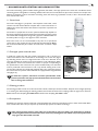
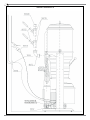
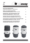
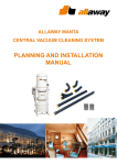
Manta 3000 and 6000 Central Vacuum Cleaners - Instructions for Usend Maintenance Table of Contents 1 ALLAWAY MANTA CENTRAL VACUUMING SYSTEM.............................................................................................................................. 3 1.1 Central Unit................................................................................................................................................................................................. 3 1.2 Dust Pipe System and Wall Inlets............................................................................................................................................................. 3 1.3 Cleaning Products........................................................................................................................................................................................ 3 1.4 Pre-separator............................................................................................................................................................................................... 3 2 USING THE MANTA CENTRAL VACUUM CLEANER.............................................................................................................................. 4 2.1 Operational Modes of the Central Unit................................................................................................................................................. 4 2.2 Vacuuming with a Central Vacuuming System....................................................................................................................................... 4 2.3 Cleaning of the Cleaning Products......................................................................................................................................................... 5 2.4 Cleaning of the Filter and Changing of the Waste Bag....................................................................................................................... 5 3 MAINTENANCE.................................................................................................................................................................................................. 6 3.1 Cleaning and Replacing the Filter............................................................................................................................................................ 6 3.2 Maintenance of the Down Draft Filter.................................................................................................................................................. 7 4 USEFUL TIPS.......................................................................................................................................................................................................... 8 4.1 If the Central Unit Will Not Start from a Wall Inlet........................................................................................................................... 8 4.2 If the Suction Power Has Weakened...................................................................................................................................................... 8 4.3 If the Suction or Exhaust Pipe System Is Blocked................................................................................................................................ 8 4.4 Inspecting the Pipe System for Compactness....................................................................................................................................... 8 5 INFORMATION ABOUT THE CENTRAL UNIT......................................................................................................................................... 9 5.1 Technical Data............................................................................................................................................................................................... 9 5.2 Manta 3000-3 Wiring Diagram................................................................................................................................................................ 9 5.3 Manta 6000-3 Wiring Diagram............................................................................................................................................................. 10 5.4 EC Declaration of Conformity for Electrical Appliances................................................................................................................ 10 6 LIST OF SPARE PARTS..................................................................................................................................................................................... 11 7 SERVICE MEMO..................................................................................................................................................................................................15 Instructions for User: Ensure that the system is composed only of original Allaway parts in accordance with the instructions. Familiarise yourself thoroughly with the instructions. Use and maintain the system as outlined in the Instructions for Use and Maintenance in order to ensure the functioning and durability of the system. The current regulations of the authorities must be observed in planning, installation and use. SYMBOLS USED IN THE INSTRUCTIONS WARNING MORE INFORMATION We reserve the right to make changes. 2 1 ALLAWAY MANTA CENTRAL VACUUMING SYSTEM The central vacuuming system includes cleaning products, wall inlets, a dust pipe system and a central unit. The Manta central vacuuming system is designed for vacuuming rubbish, indoor dust, etc. in hotels, libraries, day nurseries, schools, for example. The Allaway pre-separator must be used when vacuuming water, wet waste, large quantities of sand, or other material that differs from normal indoor dust. 1.1 Central unit The central unit [figure 1] comprises a dust separator with a filter, a dust canister and a side channel blower complete with a control central unit. In addition, the central unit features the switches required for operation and maintenance. The number of people that can use the system simultaneously depends on the layout of the dust pipe system [cleaning areas] and the type of the central unit. Manta 3000 is designed as a single-user [1] system and Manta 6000 can be used by either one [1] or two [2] users at the same time. Due to the noise, it is not recommended to stay close to an operational central unit for long periods of time [sound level approximately 70 dB(A)]. We recommend that the place where the central unit is located, is kept locked. Figure 1 1.2 Dust pipe system and wall inlets In multi-user systems the dust pipe system is designed in such a way that one suction line leads from the central unit to the cleaning area of each user [figure 4]. Attaching several users to a single suction line of 44 mm in diameter at the same time weakens the suction power and introduces a risk of blockages. When using different suction lines, however, the number of people corresponding to the specifications of the central unit can operate simultaneously. The wall inlets must be positioned in the structures in such a way that all cleaning areas can be reached. The wall inlets are airtight and equipped with a start system that triggers the central unit into operation. Steel wall inlets are equipped with a magnetic reed start [figure 2]. In multi-user systems, wall inlets are often opened while under pressure prevails in the pipe system; the wall inlets must therefore have a strong steel structure. ON OFF Figure 2 1.3 Cleaning products The cleaning products consist of a suction hose with a handle, a telescopic wand and nozzles. All parts can be bought separately or as cleaning sets. When buying the cleaning products, ensure that the suction hose coupling muff is the right one for the hose: 80912 Suction Hose Coupling Muff REED, 80914 Suction Hose Coupling Muff REED + KEY. 1.4 Pre-separator An Allaway pre-separator must be used when vacuuming liquids, wet waste, large quantities of sand, or other material that differs from normal indoor dust. The pre-separator protects the pipe system from wear and damage. The central vacuum cleaner must under no circumstances (not even with a pre-separator) be used for vacuuming flammable materials! The static electricity resulting from the airflow may create sparks which may ignite the flammable material! Keep the instructions for future reference! 3 2 USING THE MANTA CENTRAL VACUUM CLEANER 2.1 Operational modes of the central unit The operational mode is selected using the operating switch on the central unit [figure 3]. OPERATING SWITCH 0 = Maintenance Mode When the switch is in the 0 position, the central unit will not start. This mode is selected, when The dust canister is being emptied The filter is being serviced There is no need for the equipment to be on stand-by TEST = Test Mode A recurrent mode, which is ideal for testing the operation of the central unit. AUTO = Stand-by Mode Stand-by mode for normal operation. Central unit can be started from a wall inlet. Figure 3 The 0 position of the operating switch does not cut the power from the central unit. If the electrical parts of the unit are being serviced, or the property and thus the equipment will be vacant for a long period of time, the central unit must be disconnected from the mains by detaching the three-phase plug from the power socket. 2.2 Vacuuming with a central vacuuming system When the central unit is on stand-by [see section 2.1 Operational Modes of the Central Unit], vacuuming can be commenced by inserting the hose coupling muff of the suction hose into a wall inlet and by turning the red magnetic start muff into the start position [see section 1.2 Dust Pipe System and Wall Inlets]. Opening the cover of the wall inlet will require strength if the system is already operational and under pressure prevails in the pipe system. Note the division of cleaning areas [e.g. figure 4] with systems designed for several users in order to ensure sufficient suction power and the transportation of rubbish in the pipe system. Keeping the wall inlets open when it is not necessary reduces suction power in other cleaning areas. There is no risk of damaging the central unit even if several wall inlets are in use simultaneously, but the cleaning power in the nozzle will be significantly reduced and the possibility of blockages when vacuuming heavy particles (stones etc.) increases as the movement of particles weakens. Sticky substances and large shards of glass may cause blockages in the pipe system. The central vacuum cleaner must not be used for vacuuming liquids unless an appropriate pre-separator is connected to the system. The wall inlets are equipped with catchers where large particles that have entered the suction hose will be caught. Long particles are caught in the elbow coupling of the wall inlet where they are easily removable. Kuva 4 4 2.3 Cleaning of the cleaning products The cleaning products are subject to wear and tear depending on the level of usage and the floor material, and they must be replaced when necessary. The life of the equipment can be extended considerably by cleaning accumulated dirt from the equipment after use and by storing it appropriately. After vacuuming, detach the telescopic wand and the nozzles from the handle and store them separately, with the bristles of the floor/carpet nozzle drawn in. Store the hose in the hose holder. Avoid storing cleaning products in direct sunlight as long-term exposure to UV light makes the plastic parts, especially the hose, brittle and reduces their life. 2.4 Cleaning of the filter and changing of the waste bag The filling-up of the dust canister must be monitored regularly and a full bag replaced by a new one before the contents exceed the volume of the dust canister. The waste bag is changed as follows: Turn the operating switch to the 0 position [figure 3]. Turn the filter shake lever on the side of the central unit [figure 5; (A)] firmly a few times. Wait until the dust has settled into the waste bag. Release the lock lever of the dust canister (B) and bring it to the down position, thus making it possible to remove the dust canister from the central unit. Figure 5 Remove the full waste bag from the dust canister and check that there is no rubbish left at the bottom of the canister or the down draft hole. Clean the lifting plate (C) of the dust canister and ensure that the perforated plate in the dust canister is clean and correctly in place. Install the new, intact waste bag carefully into the dust canister so that the edges of the bag fold over the edges of the dust canister [figures 6 and 7]. Install the dust canister with the bag back in place and turn the lock lever of the dust canister to the up position. Turn Figure 6 the operating switch to the AUTO position. The central unit must not be used without a waste bag! Only use waste bags supplied by Allaway, product number 18092. Figure 7 5 3 MAINTENANCE When emptying the dust canister and cleaning the filter as well as whenever any other kind of maintenance is being carried out, the operating switch must be in the 0 position (section 3.1) and under pressure must be removed by opening a wall inlet. Be careful not to touch the motor or the side channel blower that protrude from the back of the unit. The temperature of these may be as high as 80°C. There are no parts in the electric motor, the side channel blower or other electric equipment that need to be serviced by the user. In case of faults, the system must be disconnected from the power supply by removing the three-phase plug from the power socket, for example, and an authorised Allaway service dealer must be contacted. 3.1 Cleaning and replacing the filter The filter of the central unit is cleaned by washing, or replaced once the suction power has decreased, after the dust canister has been emptied 20-30 times. The filter can be washed at 40°C using normal detergent. The majority of dirt is rinsed away prior to washing. After the wash, while the filter is still slightly damp, it must be brushed smooth. The filter must be dry prior to installation. The filter can be tumble-dried at a low temperature. D E Figure 8 The filter usually lasts for 5-8 washes. After washing, filters must be inspected carefully; worn or damaged filters must be replaced. F Only use filters supplied by Allaway, product number 18028. G The filter is washed or replaced as follows: Turn the operating switch to the 0 position. Shake 2.4. the dust off the filter and empty the dust canister as outlined in section Remove the eye nut (D) on top of the central unit and remove the cap (E) of the central unit [figure 8]. Figure 9 H Remove the eye nuts (F) located at the side of the central unit and open the hose tightener (G) at the back of the central unit [figure 9]. Lift the filter chamber (H) off its place [figure 10]. Undo the tightening collar of the filter [figure 10; I]. Undo the attachment strings of the filter [figure 11; J]. Replace or wash the filter as instructed. Clean the surfaces of the filter chamber and the tightening collar of the filter. Install in opposite order. I Figure 10 A Tighten the filter so that slight periodical resistance can be felt when turning the shake lever [A]. Tighten the tightening collar of the filter carefully. Replace the tightening collar if necessary. Turn the operating switch to the AUTO position. Figure 11 6 J If the vacuum cleaner has been used with a damaged or incorrectly installed filter, an authorised Allaway service dealer must inspect the cleaning system. Only use the cleaning method outlined in section 3.1. Other cleaning methods may damage the filter and cause the system to malfunction! 3.2 Maintenance of the down draft filter Allaway Manta central unit has a down draft system, the purpose of which is to hold the waste bag in its place in the dust canister. If the waste bag does not stay in place [if it rises], first remove the possible under pressure from the pipe system by opening a wall inlet and check the following: K L The waste bag must be intact and installed in accordance with the instructions for the dust canister. No rubbish must be located between the edge sealing of the edges of the dust canister and the taper of the central unit. Remove possible rubbish. The sealing of the top edge and the bottom of the dust canister must be intact and appropriately installed. Kuva 12 The perforated elevation plate at the bottom of the dust canister must be intact and clean as well as correctly installed. M If the above have been checked and the waste bag still rises out of place in the dust canister, the down draft system of the central unit must be cleaned as follows: Turn the operating switch to the 0 position. Undo the hexagonal screw (L) of the down draft filter (K) [figure 12]. Remove and clean the filter (M) and the filter cup (N) [figure 13]. Detach the process hose (O) and clean it and other parts connected to it, as well as the channel in the lifting plate of the dust canister using e.g. compressed air or metal wire. O N Kuva 13 Reassemble the parts. Turn the operating switch to the AUTO position. We recommend that an authorised Allaway service dealer service the central vacuuming system on a regular basis in order to ensure the flawless functioning of the system. Contact details for authorised Allaway service dealers can be found, for example, at www.allaway.fi. 7 4 USEFUL TIPS 4.1 If the central unit will not start from a wall inlet Check that the operating switch of the central unit is in the AUTO position. Check whether the central unit starts from other wall inlets as normal. If the central unit starts in the TEST position of the operating switch but not from the wall inlets, ensure that the weak current plug is connected to the start circuits of the wall inlets.. 4.2 If the suction power has weakened Check that there are no objects in the wall inlet that may block the airflow. Check that the suction hose is intact and that there are no objects in the hose that may block the airflow. Check that other wall inlets are closed and that they have no leaks. Check that the pipe system does not leak. Check that the dust canister is not full. Check that the filter is not blocked. Check that the dust canister is correctly in place and that the sealing is intact. 4.3 If the Suction or Exhaust Pipe System Is Blocked Replace Ensure the waste bag in accordance with section 2.4. that no fire dampers have been released in the exhaust pipe and that there are no other obstacles. Locate the blockage e.g. by sucking pieces of kitchen paper through the wall inlets. If the strips of paper end up in the waste bag, the tested length of pipe is clear. Once you have located the blockage, remove the collector pipe from the suction coupling of the central unit. Use another powerful vacuum cleaner to suck at the wall inlets of the blocked branch. If the blockage cannot be removed through suction and its location can be pinpointed, it is worth examining whether it is easy to access the pipe system without dismantling the structures or by a reasonable amount of dismantling. If the pipe system is accessible, the blockage can usually be removed easily by opening a pipe joint. Never use overpressure such as compressed air to remove blockages as overpressure breaks the pipe joints! If the blockage cannot be removed by following the above instructions, contact an authorised Allaway service dealer. 4.4 For Inspecting the pipe system for compactness Close all wall inlets and start the central unit for a maximum of 1 minute by connecting the start circuit with a metal wire. If air is escaping from the exhaust pipe after 15 seconds of running the unit, there is a leak in the pipe system. The leak must be located and repaired. 8 5 INFORMATION ABOUT THE CENTRAL UNIT 5.1 Technical data MANTA 3000-3 MANTA 6000-3 Nominal power Electrical power Drip-proof casing class Turbine overheat protector 4,0 kW 32 A 3-phase plug assembly / 25 A with pre-fuses IP34 yes 5,5 kW 32 A 3-phase plug assembly / 25 A with pre-fuses IP34 yes Measurements from turbine: Maximum volume of air 108 l/s (390 m³/h) Maximum under pressure Approx 32 kPa 108 l/s (390 m³/h) Approx 40 kPa Sound level ±2 dB in echo-free space Approx 70 dB (A) Approx 69 dB (A) Dust canister Suction hose Ø 32 mm Height Width Depth Weight 34 litres 8 or 10 meters 1965 mm 600 mm 650 mm 152 kg 34 litres 8 or 10 meters 1965 mm 600 mm 650 mm 159 kg Maximum suction reach - 1 user 70 meters - 2 users - 100 meters 60 meters 5.2 Manta 3000-3 wiring diagram Figure 14 9 5.3 Manta 6000-3 Wiring Diagram Figure 15 5.4 EU DECLARATION OF CONFORMITY FOR ELECTRICAL APPLIANCES Allaway Oy, Kangasvuorentie 32, 40320 Jyväskylä, Finland declares, that Central vacuum cleaners: MANTA 3000 - 3 MANTA 6000 - 3 have been manufactured in accordance with the applicable harmonized standards. They comply with the essential elements of low voltage Council directive (2006/95/EC) and the Council directive for compatibility on electricity (2004/108/EC) the central requirements of the Directive 2006/42/EC on the approximation of the laws of the Member States relating to machinery. 10 6 LIST OF SPARE PARTS MANTA 3000-3, MANTA 6000-3 Product number and name 10024 Weak current plug 18010 Ball knob 18012 Thermostat 80°C 18015 Filter chamber sealing 18016 Adjustment foot 18022 Hand wheel 18023 Shaft sealing 18028 Filter 18029 Filter tightening collar 18072 Elbow 18094 Inner coupling 100/125 mm 18118 Control unit AP9/1 18142 Turbine 4,0 kW (Manta 3000) 18155 Dust canister 34 l 18158 Suction coupling 76/130 mm 18159 Blow back valve R2 125 mm 18163 Elevation plate 330 mm 18092 Waste bag roll (75 l / 20 bags) 18164 Dust canister edge sealing (34 l vessel) 18165 Twist hose PU 76 mm 80932 Adjustment muff 44/50 18003B Turbine 5,5 kW (Manta 6000) 18006B Down draft filter 18013B 3-phase plug 32 A 18032A Flexible drift 100 mm 18040B Damper rubber 30x40 mm M8 18068B Plug 18071B Branch 18084B Lifting plate 415x410 18120B Process hose assembly 3/8-3/8 Down draft filter 18006B 18062 11 3000-3/6000-3 12 3000-3/6000-3 13 3000-3/6000-3 14 7 SERVICE MEMO Central Unit ________________ Dust canister emptied Filter cleaned No._______________ Implementation Date _______________________ Down draft filter serviced Dust canister emptied Filter cleaned Dust canister emptied 15 JYVÄSKYLÄ, FINLAND [email protected] www.allaway.fi 13142 rev05 en 11/2010