1
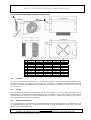
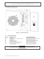
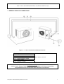
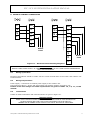
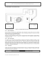
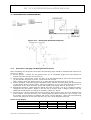
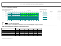
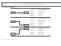
Eaton-Williams Ltd
INSTALLATION MANUAL
ICC COOLING STORAGE UNIT
ICC/ICU SYSTEM
Eaton-Williams Ltd
Station Road – Edenbridge – Kent – TN8 6EG
Tel: +44 (0)1732 866066 Fax +44(0)1732 866653
www.eaton-williams.com
0412115 B
ICC / ICU SYSTEM INSTALLATION MANUAL
INDEX
CONTENTS
PAGE
1.
Installation and Safety
3
1.1
Installation
3
1.2
Handling
3
1.3
Application
3
1.4
Electrical Connection
3
1.5
Warranty
3
1.6
Safety Procedures
3
2.
Introduction to Units
4
2.1
ICC Indoor Unit
4
2.2
ICU Outdoor Unit
4
2.3
Option Kits
4
3.
Location and Mounting of Indoor Unit (ICC)
5
3.1
Location
5
3.2
Fixing
5
3.3
Service Connections
5
4.
Indoor Unit Access (ICC)
6
4.1
Access Details / Fixings
6
5.
Location and Mounting of Outdoor Unit (ICU)
7
5.1
Location
7
5.2
Fixing
7
5.3
Service Connections
7
6.
Outdoor Unit Access (ICU)
8
6.1
Access Details / Fixings
7.
General Service Connections
8
8.
Power and Control Connections
11
8.1
Wiring-Up the Unit
11
8.2
Wiring Requirements
11
8.3
Terminations
11
9.
Disposal Procedure
12
10.
Refrigerant Pipe Connections
13
10.1
Pipe Installation
13
10.2
Unit Connections
13
10.3
Insulation
13
11.
Refrigeration Commissioning
14
11.1
Evacuation, Charging and Refrigerant Procedures
14
11.2
ICU – Recommended Line Sizes
15
9&10
11.3
Example of Line Sizing
16
12
Ancillary Service Connections
17
12.1
Condensate Removal
17
12.2
Condensate Connection
17
13
Final Checks
18
14
Wiring Diagrams
19
CE Certificate
20
January2005: E\Manuals\Others\Qualitair\ICC\0412115B
2
ICC / ICU SYSTEM INSTALLATION MANUAL
1. INSTALLATION & SAFETY
1.1 Installation
The units making up the Air Conditioning System must only be installed by a qualified engineer,
following the mandatory and local codes of practice.
1.2 Handling
Care must be taken when the units are moved or lifted to ensure that everyone and everything is
safe. When lifting equipment is used, it must be suitable and approved.
1.3 Application
Ensure that the unit is only used for suitable purpose/application.
1.4 Electrical Connection
Electrical work and connections must only be made by authorised electricians, in accordance with
mandatory regulations and local codes of practice.
1.5 Warranty
Failure to comply with the manufacturer’s installation instructions could affect the performance of the
unit and invalidate the warranty. Warranty is also subject to the implementation of a planned
service/maintenance agreement as documented in the warranty booklet supplied with the unit.
1.6 Safety Procedures
General
1. All works must be carried out in accordance with the manufacturer’s installation and operating
procedures.
2. Good working practices must be followed at all times so that Mechanical and Electrical hazards are
kept to a minimum.
3. The equipment has been fitted with doors and covers to prevent access during operation. These
must be kept in place and additional guards fitted, if necessary.
4. The equipment must be connected to an external electrical isolator if one is not supplied fitted to
the unit.
5. Servicing and maintenance must only be carried out by fully qualified and competent staff. Before
any work is started, electrically isolate the units to make sure that they cannot be switched on
accidentally and allow sufficient time for isolated parts to come to rest before removing panels.
Electrical isolation switches must be labelled to show that they are OFF during servicing and
maintenance operations.
Note: Some units are dormant in standby mode and can restart without warning if they are not
electrically isolated.
6. Care must be taken not to touch components or pipework which may be extremely hot or cold, for
a period after the unit is electrically isolated.
7. After completing any tasks ensure all guards, covers and doors are correctly refitted before
restoring the power supply to the unit.
8. Air conditioning equipment may generate unacceptable noise levels. If noise levels are
unacceptable sound and vibration attenuators may be required. For noise level guidance refer to
technical literature, or contact Qualitair, or their distributors for advice.
SPECIAL NOTE
IF ANYTHING IS NOT CLEAR, PLEASE CONTACT YOUR DISTRIBUTOR FOR CLARIFICATION.
January2005: E\Manuals\Others\Qualitair\ICC\0412115B
3
ICC / ICU SYSTEM INSTALLATION MANUAL
2. INTRODUCTION TO UNITS
2.1
ICC Indoor Unit
The ICC has been designed for installation in areas which require products or produce to be stored in
cool conditions (down to 5°C). As standard, the units are suitable for DX cooling only, but the option
of an electric heater is available.
2.2
ICU Outdoor Unit
The unit is a floor-standing condensing unit which can also be wall mounted using the ICU Wall
Bracket Option Kit. The unit is supplied complete with axial fan and guard, hermetic compressor,
shut-off service valves, fan speed controller, low pressure switch, high pressure switch, start delay
timer, winter start and an electrical section.
2.3
Option Kits
The ICC and ICU units can be supplied with option kits which will require fitting at site. Instructions
for fitting are supplied with the Option Kits.
ICC INDOOR UNIT
ICU OUTDOOR UNIT
FIGURE 2.1
SPECIAL NOTES:
CHECK THAT THE INDOOR UNIT IS CORRECTLY MATCHED TO THE OUTDOOR UNIT.
(SEE APPLICATION GUIDE)
ALL PIPE WORK, INSULATION AND ELECTRICAL CABLING IS TO BE SUPPLIED BY OTHERS.
January2005: E\Manuals\Others\Qualitair\ICC\0412115B
4
ICC / ICU SYSTEM INSTALLATION MANUAL
3. LOCATION & MOUNTING OF INDOOR UNIT (ICC)
←
→
A
B
C
D
E
F
G
H
J
K
ICC 25
475
390
805
450
680
680
62
62
300
50
ICC 35
475
390
805
450
680
680
62
62
300
50
ICC 50
475
390
805
450
680
680
62
62
300
50
ICC 60
525
440
865
525
740
680
92
32
350
50
ICC 70
525
440
865
525
740
680
92
32
350
50
Figure 3.2 – ICC Positioning
3.1
Location
The ICC unit should be mounted level on a load bearing wall or ceiling. The minimum distance from
the floor should be 1.8 metres to ensure good air convection. The side inlet grilles should have a
minimum clearance from obstruction of 100mm and the minimum clearance in front of the unit should
be 1.5 metres.
3.2
Fixing
The unit should be fixed to the wall using two-off rear fixings (1) or to the ceiling using the two-off
top fixings (2). 10mm diameter rawbolt type fixings (supplied by others) with large steel washers are
recommended for fixing to a local load bearing wall or ceiling. Locking screw holes to be used to
prevent equipment moving once installed.
3.3
Service Connections
The refrigerant pipe connections are accessed through the left hand side panel (3). Cable entry is on
the right hand side of the unit. A plastic drain connector is supplied (inside the control box) to be site
fitted onto the condensate tray.
SPECIAL NOTE
ENSURE THE INDOOR UNIT IS INSTALLED LEVEL TO PREVENT DRAINAGE PROBLEMS.
January2005: E\Manuals\Others\Qualitair\ICC\0412115B
5
ICC / ICU SYSTEM INSTALLATION MANUAL
4. INDOOR UNIT ACCESS (ICC)
↓
←
↑
→
4.1
Access Details/Fixings
Item N°
Unit Component
Access Details / Fixing
(1)
Motor / Fan
Remove 4-off
connections.
(2)
Electric Section
Remove electric right hand side panel (4).
(3)
Drip Tray
Remove 2-off screws and 4 front screws.
screw
fittings
and
disconnect
electrical
SPECIAL NOTES
DO NOT OBSTRUCT ACCESS PANELS WHEN MOUNTING UNIT
January2005: E\Manuals\Others\Qualitair\ICC\0412115B
6
ICC / ICU SYSTEM INSTALLATION MANUAL
5. LOCATION & MOUNTING OF OUTDOOR UNIT (ICU)
Figure 5.1 – ICU Unit Positioning
Figure 5.3 – ICU Wall Bracket Fixing
Table 5.1 – ICU Wall Mount Kit Fixing
ICU30
ICU40
ICU55
ICU80
Width mm
720
720
800
800
Height mm
610
610
765
765
Depth mm
250
250
320
320
Weight kg
42
42
60
64
Dim ‘y’ mm
220
220
290
290
Dim ‘Z’ mm
670
670
750
750
Figure 5.2 – ICU Unit Fixing
5.1
Location
The unit can either be mounted on a level surface or suspended from a vertical wall using the
Qualitair wall mounting Optional kit (1). The unit should always be mounted on a load bearing wall
and not a partition wall. Ensure there is sufficient free area around the unit as detailed in Figure 5.2.
5.2
Fixing
Two-off hole fixings (2) and two-off slot fixings (3) suitable for M10 fixings are provided in the base of
the unit to secure the unit to a suitable plinth, or to the wall mount bracket kit. If required, the
contractor should install the unit on anti-vibration pads.
5.3
Service Connections
The refrigerant pipe (4) and electrical connections (5) are located at the right hand end of the unit.
Ensure there is adequate air entry at the back of the unit as detailed in Figure 5.2 above.
SPECIAL NOTE
ENSURE CONDENSER HAS ADEQUATE CLEARANCE AROUND IT AND IS NOT AFFECTED BY
NEIGHBOURING CONDENSING UNITS AND OTHER OBSTRUCTIONS.
January2005: E\Manuals\Others\Qualitair\ICC\0412115B
7
ICC / ICU SYSTEM INSTALLATION MANUAL
6. OUTDOOR UNIT ACCESS (ICU)
×
Figure 6.1 – Unit Internal Access
6.1
Access Details/Fixings
Item No.
(1)
(2)
(3)
(4)
(5)
(6)
(7)
(8)
(9)
Unit Component
Fan guard
Fan/motor ((fixed to rear of fan guard)
Condenser coil
Compressor
Removable top panel
Service access panel
Reversing valve (Heat pump unit only)
Electrics/customers connection
Unit wiring diagram
Access Details/Fixings
Front access set screw fixings
Front access set screw fixings on guard
Access from rear of unit
Remove “service access panel”
Front and side access screw fixings
Front access screw fixings
Remove “service access panel”
Remove “service access panel”
Remove “service access panel”
SPECIAL NOTES
UNIT WIRING DIAGRAM IS FIXED TO INSIDE OF FRONT ACCESS PANEL (6),
HP SWITCH IS LOCATED ON THE COMPRESSOR DISCHARGE; LP SWITCH ON THE COMPRESSOR
SUCTION CONNECTION.
January2005: E\Manuals\Others\Qualitair\ICC\0412115B
8
ICC / ICU SYSTEM INSTALLATION MANUAL
7. GENERAL SERVICE CONNECTIONS
Figure 7.1 – Unit Connections and Interconnections
7.1
7.2
7.4
7.5
7.7
7.8
– Liquid Connections
– Suction Connections
- Condensing Unit
– Interconnecting Cable
– Power Cable
– Isolator / Fuses
See Tables overleaf
SPECIAL NOTES
CHECK LOCAL REGULATION FOR INDOOR / OUTDOOR ELECTRICAL ISOLATION
REQUIREMENTS AND REFRIGERATION PIPEWORK STANDARDS.
January2005: E\Manuals\Others\Qualitair\ICC\0412115B
9
ICC / ICU SYSTEM INSTALLATION MANUAL
7. GENERAL SERVICE CONNECTIONS CONT
Table 7.3 – ICC Refrigerant Connections
Liquid connections
Suction connections
ICC25
1/4”
ICC35
1/4”
ICC50
1/4”
ICC60
3/8”
ICC70
3/8”
1/2”
5/8”
5/8”
3/4”
3/4”
Table 7.4 – ICU Refrigerant Connections
Liquid connections
Suction connections
ICU30
1/4”
5/8”
ICU40
1/4”
5/8”
ICU55
1/4”
5/8”
ICU80
3/8”
3/4”
Table 7.5 – Interconnecting Cable – No. of Cores
A/C Unit
A/C Unit + Heaters
ICC/ICU30
4
4
ICC/ICU40
4
4
ICC/ICU55
4
4
ICC/ICU80
4
4
Table 7.7 – Mains Power Cable – No. of Cores
Single Phase System
230/240 V 50 Hz
Three Phase System
380/415 50Hz
ICC/ICU30
ICC/ICU40
ICC/ICU55
ICC/ICU80
3
3
3
3
N/A
N/A
N/A
5
Table 7.8- System Fuse Ratings – HRC
ICC/ICU30
ICC/ICU40
ICC/ICU55
A/C Unit
10
10
16
A/C Unit + Heaters
16
16
16
*Figures in brackets are for three phase condensing units
ICC/ICU80
20 (10)*
20 (20)*
SPECIAL NOTES :
See Section 11 for interconnecting pipe sizes over 5m.
January2005: E\Manuals\Others\Qualitair\ICC\0412115B
10
ICC / ICU SYSTEM INSTALLATION MANUAL
8. POWER & CONTROL CONNECTIONS
C
PE
PE
N
L
L
PE
E
C
PE
N
E
N
N
L
L
C
1
L
2
S
L
3
Power
Feed
C
S
R
Power
Feed
H
Figure 8.1 – Electrical Interconnecting Diagrams
SPECIAL NOTES:
ENSURE THREE PHASE SUPPLY IS CONNECTED CORRECTLY OR THE THREE PHASE COMPRESSORS
WILL RUN BACKWARDS.
8.1
Wiring-up the Unit
Electrical terminations should be made onto the screw terminal side of the indoor and outdoor unit
terminal blocks.
8.2
Wiring Requirements
Power supply – Connection of isolation power supply to the outdoor unit.
Interconnecting Wiring – Power and signal cables run between outdoor and indoor unit.
Details of the fuse ratings and cable requirements are given in tables 7.5, 7.6, 7.7, of this
manual.
8.3
Terminations
Details of cable terminations and interconnections are given in Figure 8.1.
SPECIAL NOTES:
REFER TO KIT INSTRUCTIONS FOR ELECTRICAL CONNECTION OF SITE OPTION KITS!!
DO NOT MEGGER OR FLASH TEST WITH ELECTRONIC PCB’S IN CIRCUIT!!
INDOOR AND OUTDOOR UNITS SHOULD HAVE LOCAL ELECTRICAL ISOLATORS.
January2005: E\Manuals\Others\Qualitair\ICC\0412115B
11
ICC / ICU SYSTEM INSTALLATION MANUAL
9. DISPOSAL PROCEDURES
NOTE!
All refrigerant, oils and other waste materials must be disposed of in a professional and responsible
manner in strict adherence to environmental regulations.
NOTE!
The greatest possible care should be taken at all times to avoid the release of refrigerants to
atmosphere.
The de-commissioning, dismantling and disposal of air handling units should be undertaken only by
experienced personnel and in full adherence to all safety rules, in particular protection of lungs, eyes
and skin from refrigerants, dust, etc. Only approved lifting gear and power tools should be used and
access to the work area be restricted to authorised personnel.
Disconnect the unit from the electrical supply.
Reclaim all refrigerant from the unit using approved reclaiming equipment according to the
manufacturer’s instructions. Recovery of refrigerant must be carried out only by operatives
registered to refrigerant safe handling.
Dispose of the reclaimed refrigerant through an approved recycling facility.
Separate the unit sections and remove to approved recycling facilities.
January2005: E\Manuals\Others\Qualitair\ICC\0412115B
12
ICC / ICU SYSTEM INSTALLATION MANUAL
10. REFRIGERANT PIPE CONNECTIONS
9.1C
9.1B
Figure 9.1 – Refrigerant Pipe Connections
10.1
Pipe Installation
Run the suction and liquid lines in appropriately sized refrigeration copper tubing as per the detailed
tables in Section 11.2 of this installation manual. When calculating the effective run take into account
any bends or oil traps as described in table.
A filter drier should be fitted in the liquid line.
Where the vertical separation exceeds 3 metres, oil traps must be fitted at half the vertical distance
as shown on Figure 9.1 above.
Ensure the refrigerant lines are adequately supported using
refrigerant pipe clips.
10.2
Unit Connections
The outdoor unit connections are terminated in male flare connections as detailed in tables 7.3 and
7.4 of this manual; indoor connections are plain copper tails. Place flare nuts onto the copper tube
before preparing the tube with a flaring tool (9.1C). When connecting to the male flares ensure both
surfaces are clean and coat the flared surface with refrigerant oil to help ensure a leak-free joint.
When tightening the joint use two spanners to prevent twisting of the connections as detailed in figure
9.1B above. Please note that the indoor unit is factory charged with 50psi of dry air or nitrogen which
can be safely released to atmosphere.
10.3
Insulation
Suction lines must be insulated to a minimum thickness of 3/8”. Hot areas should be avoided when
routing liquid lines and consideration should be given to separate insulation of liquid lines, where
required, to prevent heat absorption.
SPECIAL NOTE
SLEEVE, SEAL AND WATERPROOF ANY BUILDER WORKS HOLES !
January2005: E\Manuals\Others\Qualitair\ICC\0412115B
13
ICC / ICU SYSTEM INSTALLATION MANUAL
11. REFRIGERATION COMMISSIONING
Figure 10.1 – Refrigerant Schematic Diagrams
Figure – 11.2 Evacuation and Charging Connections
11.1
Evacuation, Charging and Refrigerant Procedures
After completing the refrigerant connections the following steps should be followed with reference to
Figure 11.2 above.
1) Service gauges - Connect the low pressure port (1) of a manifold gauge set to the suction line
outdoor unit shut off valve service port (2).
2) Vacuum Pump - Connect the centre line port (3) of the manifold gauge set to the vacuum pump
(4) and operate the pump to ensure a vacuum of 200 microns.
Note: Ensure gauge low pressure port (5) is open and high pressure port (6) is closed.
3) System Isolation - After achieving the specified system vacuum close the gauge low pressure port
(5) and switch off the vacuum pump. Leave the system for 1 hour and check that the vacuum is
maintained. If not, check for leaks, rectify and repeat the pumping down to 200 microns.
4) Refrigerant Charging - Open both the outside unit shut off valves (7 & 8) to release the factory
refrigerant into the system. Weigh in the site top-up charge using a charging station and any
additional extended pipe run charge as detailed in Table 10.1 above.
5) Disconnect the vacuum pump and connect the gauge high pressure port (9) to the discharge line
of the outdoor unit shut-off valve (10), ensuring that the gauge central port (3) is closed. Run
the system, allow pressures to stabilise and ensure correct operation. After final commissioning
remove the gauge set, fit all valve caps and carry out a final refrigerant leak test.
System Charge Weights
Base Charge
Site Top-up Charge
Top up charge/m > 5m
January2005: E\Manuals\Others\Qualitair\ICC\0412115B
ICU30
600g
0g
25g
ICU40
1100g
0g
25g
ICU55
1600g
50g
40g
ICU80
1900g
100g
40g
14
ICC / ICU SYSTEM INSTALLATION MANUAL
11.2 ICU – RECOMMENDED LINE SIZES
Horizontal or Downflow application (Suction Line)
Upflow application (Suction Line)
Based on 5psi (0.35bar) Pressure drop
ICU30
ICU40
ICU55
ICU80
Note:
a)
b)
c)
Line Length (m)
Table A
5
10
15
Suction
3/8”
½”
½”
Liquid
¼”
¼”
¼”
20
25
30
½”
½”
5/8”
¼”
¼”
¼”
Suction
½”
½”
½”
5/8”
5/8”
5/8”
Liquid
¼”
¼”
¼”
¼”
¼”
¼”
35
40
45
50
60
70
80
90
Max
Max
100
Table B
Size
Lift
Additional Oil
Additional Charge
R407c – kg
¾”
Suction
3/8”
5
None
>5m = 25g/m (¼” Liquid)
Suction
½”
15
Suction
½”
8
DO NOT USE THIS AREA
¾”
None
>5m = 25g/m (¼” Liquid)
DO NOT USE THIS AREA
Suction
½”
5/8”
5/8”
5/8”
5/8”
¾”
¾”
¾”
¾”
¾”
¾”
7/8”
7/8”
7/8”
7/8”
Liquid
3/8”
3/8”
3/8”
3/8”
3/8”
3/8”
½”
½”
½”
½”
½”
½”
½”
½”
½”
Suction
5/8”
5/8”
¾”
¾”
¾”
¾”
7/8”
7/8”
7/8”
7/8”
7/8”
7/8”
7/8”
7/8”
11/8”
Liquid
3/8”
3/8”
3/8”
3/8”
½”
½”
½”
½”
½”
½”
½”
½”
½”
½”
½”
None
>5m = 40g/m (3/8” Liquid)
>30m = 105g/m (1/2” liquid)
Suction
¾”
30
None
>5m = 40g/m (3/8” Liquid)
>30m = 105g/m (1/2” liquid)
= DO NOT USE IN THIS AREA.
Crankcase heaters are required where system charge exceeds 4.5kg and DOES NOT contain an accumulator.
Maximum pipe run stated in Table A, must include the reduction allowance (equivalent length) for vertical lifts and fittings indicated in Table B below.
Table C General fitting losses - equivalent straight lengths in metres.
Fitting
45° Bend
90° Bend Short Radius
90° Bend Long Radius
180° Bend Short Radius
180° Bend Long Radius
90° Elbow
Oil Trap
E\Manuals\Others\Qualitair\ICC\0412115
3/8”
0.12
0.37
0.24
0.73
0.46
0.67
0.74
½”
0.15
0.43
0.27
0.91
0.55
0.85
0.86
Pipe Size
5/8”
¾”
0.18
0.21
0.49
0.55
0.30
0.37
1.10
1.28
0.64
0.76
1.04
1.25
0.98
1.10
7/8”
0.24
0.61
0.43
1.46
0.85
1.46
1.22
15
11/8”
0.30
0.79
0.52
1.83
1.07
1.89
1.58
ICC / ICU SYSTEM INSTALLATION MANUAL
11.3 EXAMPLE OF LINE SIZING
45m
ICU80
ICU80
EVAP
10m
FROM TABLE
A
Horizontal Suction to be 7/8”
Horizontal Liquid to be ½”
TABLE B
Not applicable
Added Oil
None required
Added Gas
105g x 40m
FROM TABLE
A
Horizontal Suction to be 7/8”
Horizontal Liquid to be ½”
TABLE B
Vertical Suction 3/4"
Vertical Liquid ½”
Added Oil
None required
Added Gas
105g x 40m
FROM TABLE A
Horizontal Suction to be 7/8”
Horizontal Liquid to be ½”
TABLE B
Not applicable
Added Oil
None required
Added Gas
105g x 40m
25m
10m
10m
25m
ICU80
EVAP
EVAP
10m
January2005: E\Manuals\Others\Qualitair\ICC\0412115B
16
ICC / ICU SYSTEM INSTALLATION MANUAL
12. ANCILLARY SERVICE CONNECTIONS
↑
←
→
Figure 11.1 – Condensate Services
12.1
Condensate Removal
As standard the condensate is removed by gravity drainage on the bottom of the unit.
12.2
Condensate Connection
A plastic hose connector is supplied loose (to be found inside electrical section) with the unit for site
fitting of the condensate tray. In order to fit the connector it is necessary to remove the drain tray (1).
The tray is removed by undoing the two-off screw fittings (2) and the four front screw fixings (3). After
fitting the connector re-fit the condensate tray.
Note: After installation, pour 2 litres of water into drain tray and check for good drainage.
SPECIAL NOTE
ENSURE ALL CONNECTIONS EXTERNAL TO THE UNIT CASING AND DRAIN PIPEWORK ARE ADEQUATELY
INSULATED TO PREVENT FREEZING OR CONDENSATION.
January2005: E\Manuals\Others\Qualitair\ICC\0412115
17
ICC / ICU SYSTEM INSTALLATION MANUAL
13. FINAL CHECKS
Check
1)
Have all options kits been fitted ?
2)
Have units been mounted level and correct drainage been checked by pouring 2 litres
of water into drip tray?
3)
Has the ICU (outdoor) drain been connected, if required?
4)
Have the suction line and condensate drains been adequately insulated?
5)
Has the correct HRC external fusing / isolating been installed?
6)
Has additional extended pipe-run refrigerant charge been measured into the system,
where necessary?
7)
Has the indoor condensate drain been trapped ?
8)
Is there adequate room and access to remove the access panels ?
9)
Has the control system been explained to the customer and the operating manual sheet
handed over with the appropriate sections completed?
10)
Has the warranty booklet been read and completed? Note:- If a service contract is not
taken out only a 1-year warranty is applicable.
January2005: E\Manuals\Others\Qualitair\ICC\0412115
18
ICC / ICU SYSTEM INSTALLATION MANUAL
14 WIRING DIAGRAM NUMBERS
This page gives wiring diagram numbers for each type of indoor (ICC) and outdoor (ICU) unit
manufactured by Qualitair. The diagrams themselves are supplied with the unit and are located in the
electrical section. Please ensure the correct issue drawing is used with the relevant system; refer to
Qualitair, if necessary.
Unit Ref
ICC25,
35,
45/55,
60,
70
ICC25,
35,
45/55,
60,
70
ICC25,
35,
45/55,
60,
70
ICC25,
35,
45/55,
60,
70
Phase
Wiring
Diagram
A3LBD130
Function
Cooling Only
Type
Electromech
Heat Only
Electromech
A3LBD131
Cooling Only
Electronic
A3LBD132
Heat Only
Electronic
A3LBD133
Part N°
J70632
J70642
J70662
J70682
J70692
J70631
J70641
J70661
J70681
J70691
J70630
J70640
J70660
J70680
J70690
J70633
J70643
J70663
J70683
J70693
Use the above Wiring Diagrams until ICC Unit Serial N° Q09734.
Thereafter, use Wiring Diagrams listed below.
Unit Ref
ICC25,
35,
45/55,
60,
70
ICC25,
35,
45/55,
60,
70
ICC25,
35,
45/55,
60,
70
ICC25,
35,
45/55,
60,
70
ICU30,
40
ICU55,
80
ICU80
ICU100
ICU100,
135,
170
ICU30,
40
ICU55,
80,
100
ICU80,
100,
135,
170
ICU80,
100,
135,
170
ICU40,
55,
80,
100
Type
Electromech
Heat Only
Electromech
A3LBD149
Cooling Only
Electronic
A3LBD150
Heat Only
Electronic
A3LBD151
Cooling Only
Condensing Unit
1-ph (TS FSC)
A3LBD137
Cooling Only
Condensing Unit
1-ph (TS FSC)
A3LBD138
Cooling Only
Cooling Only
Cooling Only
Condensing Unit
Condensing Unit
Condensing Unit
3-ph (TS FSC)
1-ph (PS FSC)
3-ph (PS FSC)
A3LBD139
A3LBD140A
A3LBD141A
Cooling Only
Condensing Unit
1-ph (PS FSC)
A3LBD143
Cooling Only
Condensing Unit
1-ph (PS FSC)
A3LBD144
Cooling Only
Condensing Unit
3-ph (PS FSC)
A3LBD145
Heatpump
Condensing Unit
3-ph (PS FSC)
A3LBD146
Heatpump
Condensing Unit
1-ph (PS FSC)
A3LBD147
January2005: E\Manuals\Others\Qualitair\ICC\0412115
Phase
Wiring
Diagram
A3LBD148
Function
Cooling Only
Part N°
J70632
J70642
J70662
J70682
J70692
J70631
J70641
J70661
J70681
J70691
J70630
J70640
J70660
J70680
J70690
J70633
J70643
J70663
J70683
J70693
J90733
J90743
J90763
J90783
J90784
J90723
J90724
J90714
J90794
J90733
J90743
J90763
J90783
J90723
J90784
J90724
J90714
J90794
J90786
J90726
J90716
J90796
J90745
J90765
J90785
J90725
19
ICC / ICU SYSTEM INSTALLATION MANUAL
CE CERTIFICATE
Eaton-Williams Air Conditioning
(Eaton-Williams Ltd)
Station Road – Edenbridge - Kent - TN8 6EG - England
Telephone ... 44 (0)1732 866055
Telefax ... (0)1732 863461
ELECTROMAGNETIC COMPATIBILITY DIRECTIVE
89/336/EEC
MACHINERY DIRECTIVE
EC Declaration of Conformity
As Defined by the EC Council Directive on Machinery
89/392/EEC Annex IIA and amended by
91/368/EEC - 93/44/EEC & 93/68/EEC
We declare that the equipment designated below,
on the basis of design and construction in the form marketed by us and
when installed and operated in accordance with our information and instructions,
conforms to the EMC Directive, the PED and the essential Health and Safety requirements of the Machinery
Directive.
If alterations are made to this equipment without our approval,
this declaration becomes invalid. Furthermore, this equipment may be
assembled into other systems which may also constitute machinery and shall
not be put into service until the assembled system has been declared in conformity
with the Machinery Directive.
Model
Serial N°
Standards Applied
EMC
EMC
Low Voltage
Pressure Equipment
Controls Applied
BS EN 292-Pt2
BS EN50081-1
BS EN50082-1
EN60204 pt1
prEN14276-2
BS EN ISO 9001: 1994
BSI Registered Company Q5026
Gerry Stapley
Managing Directors
Qualitair
January2005: E\Manuals\Others\Qualitair\ICC\0412115
Edenaire
Gary Martin
Moducel
20
ICC / ICU SYSTEM INSTALLATION MANUAL
STATION ROAD
EDENBRIDGE
KENT
TN8 6EG
TEL: (01732) 866066
FAX:(01732) 867937
AN EATON-WILLIAMS COMPANY
As part of the policy of continuous product improvement, we reserve the right to alter specifications without notice
January2005: E\Manuals\Others\Qualitair\ICC\0412115
21