1
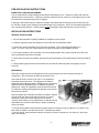
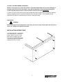
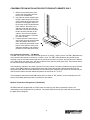
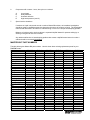
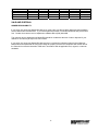
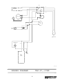
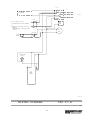
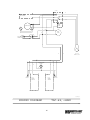
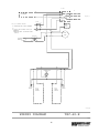
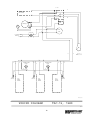
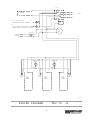
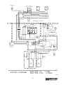
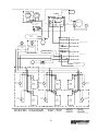
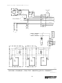
Installation & Operations Manual
Master-Bilt Products
908 Highway 15 North
New Albany, MS 38652
Phone: (800) 684-8988
PN 217-90000
10/16/03
2
TABLE OF CONTENTS
INTRODUCTION………………………………….……………………………………………………………………
4
STORE CONDITIONS…………………………….……………….…..…………………………………………….. 4
WARNING LABELS AND SAFETY INSTRUCTIONS………..…..……………………………………………… 5
PRE-INSTALLATION INSTRUCTIONS………………………..…..………………………………….…………… 6
Inspection for ShippingDamage……………………………………………………………….…………… 6
INSTALLATION INSTRUCTIONS………………………………………………………………………………….. 7
General Instructions…………………………………………………………………………………………. 7
Location………………………………………………………………………………………………………..7
Dimensional Data……………………………………………………………………………………………..7
STARTING PROCEDURE…………………………………………………………………………………………….8
FINAL CHECK LIST…………………………………………………………………………………….……………..8
SERVICE INSTRUCTIONS……………………………………………………………………………………………9
MASTER-BILT PART NUMBERS…………………………………………………………………………………...10
SALE AND DISPOSAL………………………………………………………………………………………………..11
WIRING DIAGRAMS TAC27.…………………………………………….……………………….………………….12
WIRING DIAGRAMS TAC27R.…………………………………………….……………………….………………..13
WIRING DIAGRAMS TAC48.…………………………………………….……………………….………………….14
WIRING DIAGRAMS TAC48R.…………………………………………….……………………….………………..15
WIRING DIAGRAMS TAC74…………………………………………….……………………….……………….….16
WIRING DIAGRAMS TAC74R.…………………………………………….……………………….………………..17
WIRING DIAGRAMS TAF27.…………………………………………….……………………….…………………. 18
WIRING DIAGRAMS TAF48/TAF74…………………………………….……………………….…………………. 19
WIRING DIAGRAMS TAF-ALL REMOTE AND QUICK CONNECT….……………………….……………….. 20
3
INTRODUCTION
Thank you for purchasing a Master-Bilt cabinet. This manual contains important instructions for installing,
using and servicing a Master-Bilt TAF/TAC case. A parts list is included in with this manual. Read all these
documents carefully before installing or servicing your equipment.
STORE CONDITIONS
The Master-Bilt TAF/TAC cases are designed to operate in the controlled environment of an air conditioned
store. The store temperature should be at or below 75°F and a relative humidity of 55% or less. At higher
temperature or humidity conditions, the performance of these cases may be affected and the capacity
diminished. It is not uncommon in a newly constructed store for the temperature and humidity to be above
design conditions. These excessive conditions may produce sweating in the case until the store is operational
and the ambient environment is more desirable.
The Master-Bilt TAF/TAC should not be positioned where it is directly exposed to rays of sun or near a direct
source of radiant heat or air flow. This will adversely affect the case and will result in poor performance.
If this case is to be located against a wall there should be at least 4” space between the wall and the back of
the case. This space will allow for the circulation of air behind the case which will prevent condensation on the
exterior surfaces.
NOTICE
Read this manual before installing your cabinet. Keep the manual and refer to it before doing any
service on the equipment. Failure to do so could result in personal injury or damage to the cabinet.
DANGER
Improper or faulty hook-up of electrical components of the refrigeration units can result in severe
injury or death.
All electrical wiring hook-ups must be done in accordance with all applicable local, regional or national
standards.
NOTICE
Installation and service of the refrigeration and electrical components of the cabinet must be
performed by a refrigeration mechanic and/or a licensed electrician.
4
The portions of this manual covering refrigeration and electrical components contain technical instructions
intended only for persons qualified to perform refrigeration and electrical work.
This manual cannot cover every installation, use or service situation. If you need additional information, call or
write us:
Customer Service Department
Master-Bilt Products
Highway 15 North
New Albany, MS 38652
Phone (800) 684-8988
Fax (800) 684-8988
WARNING LABELS AND SAFETY INSTRUCTIONS
This symbol is the safety-alert symbol. When you see this symbol on your cabinet or in this
manual, be alert to the potential for personal injury or damage to your equipment.
Be sure you understand all safety messages and always follow recommended precautions and safe operating
practices.
NOTICE TO EMPLOYERS
You must make sure that everyone who installs, uses or services your cabinet is thoroughly familiar
with all safety information and procedures.
Important safety information is presented in this section and throughout this section and throughout the
manual. The following signal words are used in the warnings and safety messages:
DANGER:
Severe injury or death will occur if you ignore the message.
WARNING: Severe injury or death can occur if you ignore the message.
CAUTION: Minor injury or damage to your cabinet can occur if you ignore the message.
NOTICE:
This is important installation, operation or service information. If you ignore the
message, you may damage your cabinet.
The warning and safety labels shown throughout this manual are placed on your Master-Bilt Products
cabinet at the factory. Follow all warning label instructions. If any warning or safety labels become
lost or damaged, call your customer service department at (800) 684-8988 for replacements.
CAUTION!
GROUND REQUIRED
FOR SAFE OPERATION
This label is located on top of the electrical control
label and on the wiring channel.
This label is attached to the cabinet power cord
on models with a power cord.
5
PRE-INSTALLATION INSTRUCTIONS
INSPECTION FOR SHIPPING DAMAGE
You are responsible for filing all freight claims with the delivering truck line. Inspect all cartons and crates for
damage as soon as they arrive. If damage is noted to shipping crates or cartons or if a shortage is found, note
this on the bill of lading (all copies) prior to signing.
If damage is discovered when the cabinet is uncrated, immediately call the delivering truck line and follow up
the call with a written report indicating concealed damage to your shipment. Ask for an immediate inspection of
your concealed damage item. Crating material must be retained to show the inspector from the truck line.
INSTALLATION INSTRUCTIONS
GENERAL INSTRUCTIONS
1. Be sure the equipment is properly installed by competent service people.
2. Keep the equipment clean and sanitary so it will meet your local sanitation codes.
3. Rotate your stock so that older stock does not accumulate. This is especially important for ice
cream. A "First-In, First-Out" rotation practice will keep the products in good salable condition.
4. Do not place product in the case when it is soft or partially thawed. Also, product should not be put in the
case for at least 6 hours after it is started.
5. Stock cases as quickly as possible, exposing only small quantities to store temperatures for short periods of
time.
6. When replacing burned out fluorescent tubes, be sure that the electrical power to the lighting circuit is
turned off.
MECHANICAL
Remove front grille and check refrigeration lines to see that they are free (not touching each other or
compressor). Spin condenser fan blade to see that it is free.
Check that all service valves (2) are open. Cut compressor
hold-down strap and remove. The springs are secured for
shipping by either tightening bolts or shipping strap. Remove the
strap or loosen the hold-down bolts so that the compressor
floats freely. Check all refrigeration lines and electrical conduit
for rubbing or chaffing, paying particular attention to area where
lines enter the cabinet.
Remove cabinet from crate base and slide into location. Cabinet
must be level from side to side and front to back for correct
draining of coil pan and for self-closing doors to operate
correctly. Allow minimum of 4” between back of cabinet and wall
and between top of cabinet and ceiling for proper condensing
unit air circulation.
To comply with Sanitation requirements the cabinet must be mounted on legs (6” high min.) or casters or the
base must be sealed to the floor with an N.S.F. listed silicone sealant.
To comply with UL requirements the cabinet must have a minimum clearance of 4” at the top, 6” at the rear
and 0” at each side.
6
NOTICE TO STORE OWNERS / MANAGERS
Moisture or liquid around or under the cabinet is a potential slip/fall hazard for persons walking by or
working in the general area of the cabinet. Any cabinet malfunction or housekeeping problem that
creates a slip/fall hazard around or under the cabinet should be corrected immediately.
If moisture or liquid is observed around or under a Master-Bilt cabinet, an immediated investigation should be
made by qualified personnel to determine the source of the moisture or liquid. The investigation should
determine if the cabinet is malfunctioning or if there is a drain pipe leaking.
ELECTRICAL
WARNING
Before servicing electrical components in the case or the doors or door frames make sure all power to
case is off. Always use a qualified technician.
INSTALLATION INSTRUCTIONS
To comply with N.S.F. requirements,
7this cabinet must be mounted on
casters, legs (6” high min.) or the
base must be sealed to the floor.
The casters provided with this case
screw into the holes from which the
shipping bolts were removed.
7
CONDENSATE PAN INSTALLATION FOR TOP MOUNT CABINETS ONLY
1. Before moving cabinet into place,
remove the condensate pan from
the top unit compartment.
2. Using the two screws supplied with
the pan, attach the pan to the back
of the cabinet at the two holes near
the bottom of the plastic drain line.
Be sure pan is NOT located directly
under cabinet. When the pan is
attached, feed drain line into the
open hole in screen and clamp the
heater conduit to the back of the
cabinet. Due to this condensate
pan, this case must be a minimum
of 6” from the wall.
3. If cabinet must be located next to
wall on legs, the pan can be located
under the cabinet. When this is
done, steam will accumulate on the
bottom of the cabinet if there is not
adequate ventilation, and rusting of
the bottom of the cabinet will occur.
Low Temperature Freezers – TAF Models
The TAF - 27 models are cord connected and operate on a 15 amp, 115/60/1 circuit. The TAF – 48 models are
cord connected and operate on a 20 amp, 115/60/1 circuit. The TAF – 74 models have two junction boxes
mounted on top of the cabinet at the right rear for permanent connection to power. One junction box is labeled
115v. (black,white and green lead) ; the other is labeled 230v. (black,red and green lead). These boxes should
be connected to their respective power source.
Check inside the cabinet for the power requirement for each cabinet. The label is located in the upper left hand
corner. These TAF models are equipped with timers and electric defrost with a defrost termination and fan
delay thermostat. Because of this thermostat, on initial start up the evaporator fan motors will not start and you
cannot initiate a defrost until the cabinet temperature is lowered to 10°F to 20°F
The temperature thermostat on the TAF models does not have an “Off” position, so the condensing unit will
start up immediately when the power is connected to the cabinet.
Medium Temperature Refrigerators (TAC Models)
All TAC models are equipped with a 115/60/1 lead cord and plug cap. When connected to power, the
condensing unit and evaporator fan (s) will start. The mullion heaters will heat and, when the door is opened,
the lights will be energized.
8
FINAL CHECK LIST
A.
Check setting of defrost timer:
1. Four defrost/24 hours, with 30 minute fail safe. (TAF ONLY)
B.
Check operating pressures.
C.
Check electrical requirements of unit to supply voltage.
D.
Set temperature control for desired temperature range.
E.
Check sight glass for proper refrigerant charge.
F.
Check system for proper defrost settings and operation.
G.
Check condensing unit for vibrating or rubbing tubing. Dampen and clamp as required.
H.
All valves should be completeley open counter-clockwise.
I.
Check packing nts on all service valves.
J.
Replace all service valve caps and latch unit covers.
SERVICE INSTRUCTIONS (Trouble Shooting Guide)
1.
High head pressure and high back pressure:
A.
B.
2.
Low back pressure and low head pressure:
A.
B.
C.
3.
Coil blocked with frost or ice (see #4).
Refrigerant undercharged.
Control set too warm.
Air screen disturbance.
Coil blocked with frost or ice:
A.
B.
C.
D.
5.
Restriction in system.
Refrigerant undercharged.
Leak in system.
Pressures normal – cabinet warm:
A.
B.
C.
D.
4.
Condenser coil clogged or restricted.
Condenser fan motor defective.
Defective temperature control.
Time clock not operating properly.
Improper time clock setting.
Defrost heater not operating.
E.
F.
G.
I.
Compressor starts and runs – but cycles on overload:
A.
B.
C.
D.
Low voltage.
Dropped phase (3 phase).
Overload protector defective.
High head pressure (see#1).
9
P-trap in drain not installed.
Doors aren’t sealing when closed.
Evaporator fan motor defective.
Low voltage.
6.
Compressor will not start – hums, but cycles on overload:
A.
B.
C.
D.
7.
Low voltage.
Relay defective.
Overload defective.
High head pressure (see #1).
Special service situations:
If moisture or liquid is observed around or under a Master-Bilt cabinet, an immediate investigation
should be made by qualified personnel to determine the source of moisture or liquid. The investigation
made should determine if the cabinet is malfunctioning or if there is a simple housekeeping problem.
Moisture or liquid around or under a cabinet is a potential slip/fall hazard for persons walking by or
working in the general area of the cabinet.
Any cabinet malfunction or housekeeping problem that creates a slip/fall hazard around or under a
cabinet should be corrected immediately.
MASTER-BILT PART NUMBERS
The table below gives Master-Bilt part numbers. Use this chart when ordering replacement parts for your
TAC/TAF cases.
Description
TAC-27
TAC-48
TAC-74
TAF-27
TAF-48
TAF-74
Bulb
23-00343
23-00343
23-00343
23-00343
23-00343
23-00343
Bulb Holder
23-01080
23-01080
23-01080
23-01080
23-01080
23-01080
Bulb Shield
23-01465
23-01465
23-01465
23-01465
23-01465
23-01465
Caster W \ Brake
27-00591
27-00591
27-00591
27-00591
27-00591
27-00591
Casters W \ O Brake
27-00590
27-00590
27-00590
27-00590
27-00590
27-00590
Capillary Tube
11-01450
11-01450
11-01451
Coil Defrost Heater
17-00443
17-09113
17-09076
Condensate Heater
17-00421
17-00421
17-00421
17-00421
17-00421
17-00421
Condensing Unit
01-01471
01-01471
01-01472
01-01488
01-01510
01-01487
Def. Term. Fan Delay
19-13195
19-13195
19-13195
Digital Thermometer
19-13271
19-13271
19-13271
19-13271
19-13271
19-13271
Door Frame Heater
17-09148
17-09144
17-09144
17-09449
17-09142
17-09142
Door Gasket
37-01207
37-01211
37-01211
37-01207
37-01211
37-01211
Door Handle
35-01488
35-01488
35-01488
35-01488
35-01488
35-01488
Door Hinge Assembly A35-01501
A35-01501
A35-01501
A35-01501
A35-01501
A35-01501
Door Light Switch
35-01506
35-01506
35-01506
35-01506
35-01506
35-01506
Door Opening Trim
29-01481
29-01481
29-01481
29-01481
29-01481
29-01481
Drain Line Heater
17-00404
17-00404
17-00404
Drier
09-09308
09-09308
09-09308
09-09171
09-09506
09-09506
Evaporator Coil
07-00750
07-00135
07-00135
07-00750
07-13089
07-13089
Evaporator Fan Blade
15-01184
15-01184
15-01184
15-01184
15-01184
15-01184
Evaporator Fan Guard 25-00205
25-00205
25-00205
25-00205
25-00205
25-00205
Evaporator Fan Motor
13-00685
13-00685
13-00685
13-00685
13-00685
13-00685
Expansion Valve
09-09187
09-09542
09-09542
Female Plug
21-00577
Front Control
Heater Safety Control
19-01307
19-01164
19-01164
Leg
27-00558
27-00558
27-00558
27-00558
27-00558
27-00558
Pilaster
33-01408
33-01408
33-01408
33-01408
33-01408
33-01408
Pressure Control
19-13173
19-13173
Power Cord
21-00312
21-00312
21-00312
21-01454
21-01454
10
Shelf Clips
Shelves
Temperature Control
Thermometer
Timer
33-01011
33-01455
19-00903
33-01011
33-01456
19-00903
33-01011
33-01456
19-00903
33-01011
33-01455
19-13607
33-01011
33-01456
19-13607
33-01011
33-01456
19-13607
19-00817
19-00817
19-00815
SALE AND DISPOSAL
OWNER RESPONSIBILITY
If you sell or give away your Master-Bilt cabinet you must make sure that all safety labels and the Installation Service Manual are included with it. If you need replacement labels or manuals, Master-Bilt will provide them
free. Contact the customer service department at Master-Bilt at (800) 684-8988.
The customer service department at Master-Bilt should be contacted at the time of sale or disposal of your
cabinet so records may be kept of its new location.
If you sell or give away your Master-Bilt cabinet and you evacuate the refrigerant charge before shipment,
Master-Bilt recommends that the refrigerant charge be properly recovered in complience with section 608 of
the Clean Air Act effective November 1995 and in accordance with all applicable local, regional, or national
standards.
11
J BOX
W
CONDENSATE
PAN HEATER
BK
TEMP.
CONT.
COMPRESSOR
COND
FAN
BK
EVAP.
FANS
W
TRANSFORMER
DIGITAL
THERM.
115/60/1
NEMA #5-15P
INCANDESCENT
LIGHT
W/BL
B
R
W
R
R
DOOR
FRAME
HEATER
LIGHT
SWITCH
07/19/95
TAC-27,-27HD
WIRING DIAGRAM
TC27
12
J BOX
W
CONDENSATE
PAN HEATER
115/60/1
BK
J BOX
W
115/60/1 CONTROL CIRCUIT
TEMP.
CONT.
TO CONDENSING UNIT POWER TERMINALS
BR
OR
TO LIQUID LINE SOLENOID VALVE COIL
TERMINALS.
(CONDENSING UNIT ON SEPERATE POWER
SUPPLY.)
BK
EVAP.
FANS
W
TRANSFORMER
DIGITAL
THERM.
W/B
R
INCANDESCENT
LIGHT
B
W
R
R
DOOR
FRAME
HEATER
LIGHT
SWITCH
07/19/95
WIRING DIAGRAM
TAC-27-R
TC27R
13
J BOX
W
CONDENSATE
PAN HEATER
BK
TEMP.
CONT.
COMPRESSOR
COND
FAN
BK
EVAP.
FANS
W
TRANSFORMER
DIGITAL
THERM.
W
R
B
115/60/1
NEMA 5-15P
R
INCANDESCENT
LIGHT
W
W
B
B
W
R
R
LIGHT
SWITCH
R
DOOR
FRAME
HEATER
DOOR
FRAME
HEATER
LIGHT
SWITCH
07/19/95
WIRING DIAGRAM
TAC-48,-48HD
TC48
14
J BOX
W
CONDENSATE
PAN HEATER
115/60/1
BK
J BOX
W
115/60/1 CONTROL CIRCUIT
TEMP.
CONT.
TO CONDENSING UNIT POWER TERMINALS
BR
OR
TO LIQUID LINE SOLENOID VALVE COIL
TERMINALS.
(CONDENSING UNIT ON SEPERATE POWER
SUPPLY.)
BK
EVAP.
FANS
W
TRANSFORMER
DIGITAL
THERM.
W
R
W
B
INCANDESCENT
LIGHT
W
B
R
B
W
R
R
LIGHT
SWITCH
R
DOOR
FRAME
HEATER
DOOR
FRAME
HEATER
LIGHT
SWITCH
07/19/95
WIRING DIAGRAM
TAC-48-R
TC48R
15
J BOX
W
CONDENSATE
PAN HEATER
BK
TEMP.
CONT.
COMPRESSOR
COND
FAN
BK
EVAP.
FANS
W
TRANSFORMER
DIGITAL
THERM.
W
R
W
B
INCANDESCENT
LIGHT
R
W
B
W
INCANDESCENT
LIGHT
LIGHT
SWITCH
R
W
B
R
R
DOOR
FRAME
HEATER
115/60/1
NEMA #5-15P
W
R
R
B
LIGHT
SWITCH
R
DOOR
FRAME
HEATER
DOOR
FRAME
HEATER
LIGHT
SWITCH
07/19/95
WIRING DIAGRAM
TAC-74, 74HD
TC74
16
J BOX
W
CONDENSATE
PAN HEATER
115/60/1
BK
115/60/1 CONTROL CIRCUIT
TEMP.
CONT.
TO CONDENSING UNIT POWER TERMINALS
OR
TO LIQUID LINE SOLENOID VALVE COIL TERMINALS
(CONDENSING UNIT ON SEPERATE POWER SUPPLY)
BK
EVAP.
FANS
W
TRANSFORMER
DIGITAL
THERM.
R
W
B
INCANDESCENT
LIGHT
R
W
B
R
B
W
W
R
R
R
R
LIGHT
SWITCH
W
INCANDESCENT
LIGHT
DOOR
FRAME
HEATER
LIGHT
SWITCH
R
DOOR
FRAME
HEATER
DOOR
FRAME
HEATER
LIGHT
SWITCH
07/19/95
WIRING DIAGRAM
TAC-74
-R
TC74R
17
INCANDESCENT
LIGHT
DEFROST TERMINATION,
FAN DELAY THERMOSTAT
TEMP.
CONT.
1
3
EVAP.
FAN
2
W
OR
BR
BL
R
BK
DRAIN LINE HEATER
Y
DEFROST HEATER
W
HEATER
LIMIT SW.
EVAPORATOR HOUSING
TIMER
BK
CONT.
PRES.
BL
OR
Y
(OPTIONAL)
3
3
4
COMPRESSOR
X
COND
FAN
TM
1
N
2
W
BK
W
COND.
EVAP.
W
SWITCH
Y
OR
BR
BL
W
W
R
BK
W
W
W
W
BK
BK
POWER SUPPLY
115/60/1
NEMA #5-20P
DIGT. THER.
TRANSFORMER
W
W
G
BK
BK
BK
BK
R
ELECTRICAL TRAY
W
BK
R
BK
W
W
LIGHT
SWITCH
BK
R
DIGITAL
THERM.
LIGHT
SWITCH
R
R
DOOR
FRAME
HEATER
DOOR
FRAME
HEATER
(WHEN PROVIDED)
5/11/00
WIRING DIAGRAM
TAF/TUF-27, -27HD,
TAF/TUF-27H, -27HHD
TF27-HARNS
18
TAF/TUF-48HD/74HD SERIES (115/208-230/60/1
TEMP.
CONT.
EVAP.
FAN
OR
TIMER
EVAP.
FAN
3
4
X
BR
TM
WHEN PROVIDED
YEL
DEFROST TERM. &
FAN DELAY
1
2
N
COMPRESSOR
BK
COND
FAN
1
3
2
DEFROST
HEATER
BK
R
INCANDESCENT
LIGHT
INCANDESCENT
LIGHT
208-230/60/1
G
HEATER
SAFETY
G
DRAIN LINE HTR.
WHEN PROVIDED
BK
115/60/1
W
TRANSFORMER
CONDENSATE
EVAPORATOR
DIGITAL
THERMOMETER
BK
W
R/W
R
R
LIGHT
SWITCH
DOOR
FRAME
HEATER
R
LIGHT
SWITCH
R\W
DOOR
FRAME
HEATER
LIGHT
SWITCH
DOOR
FRAME
HEATER
R\W
R\W
R
R
LIGHT
SWITCH
DOOR
FRAME
HEATER
R
LIGHT
SWITCH
R\W
DOOR
FRAME
HEATER
R\W
LIGHT
SWITCH
DOOR
FRAME
HEATER
R\W
WHEN PROVIDED
WIRING DIAGRAM
TAF\TUF
7/20/00
-48HD, -74HD
-4HHD, -74HHD
TAF-TUF-23DR-HD-HHD
19
TAF/TUF-27/48/74 SERIES - REMOTE/QUICK CONNECT (208-230\60\1)
OR
EVAP.
FANS
FIELD MOUNTED
SOLENOID
BR
EVAP.
FANS
TEMP.
CONT.
SOL.
BK
OR
OR
BR
DEFROST TERMINATION,
FAN DELAY THERMOSTAT
BK
OR
TO TERMINAL #4
R
TO TERMINAL #N
R
BL
BL/W
BL/W
TO TERMINAL #X
Y\W
Y/W
TO TERMINAL #3
R
Y\W
TO CONDENSING UNIT
208/230/60/1
BR
IF PROVIDED
G
J- BOX
HEATER
LIMIT SW.
COND. PAN HTR.
DEFR.
HEATER
BK
DRAIN LINE HEATER
W
J- BOX
BK
W
G
115/60/1
TSFR
DIGITAL
THERM.
W
W
R
BK/W
INCANDESCENT
LIGHT
BK
W
R
BK/W
W
LIGHT
SWITCH
BK
INCANDESCENT
LIGHT
W
DOOR #3 IF PROVIDED
BK/W
R
R
R
R
DOOR
FRAME
HEATER
BK
W
R
R
W
W
LIGHT
SWITCH
DOOR
FRAME
HEATER
DOOR
FRAME
HEATER
LIGHT
SWITCH
DOOR #2 IF PROVIDED
7/18/00
WIRING DIAGRAM (TAF/TUF REMOTE/QUICK CONNECT)
TAF-TUF-123DR-R-Q
20