1
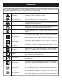
OPERATOR’S MANUAL 3-N-1 HI-SPEED GASOLINE PRESSURE WASHER RPW2500WB F GB D E I P NL CZ RU RO PL 3-N-1 HI-SPEED GASOLINE PRESSURE WASHER 3-N-1 HI-SPEED GASOLINE PRESSURE WASHER 3-N-1 HI-SPEED GASOLINE PRESSURE WASHER 3-N-1 HI-SPEED GASOLINE PRESSURE WASHER 3-N-1 HI-SPEED GASOLINE PRESSURE WASHER 3-N-1 HI-SPEED GASOLINE PRESSURE WASHER 3-N-1 HI-SPEED GASOLINE PRESSURE WASHER 3-N-1 HI-SPEED GASOLINE PRESSURE WASHER 3-N-1 HI-SPEED GASOLINE PRESSURE WASHER 3-N-1 HI-SPEED GASOLINE PRESSURE WASHER 3-N-1 HI-SPEED GASOLINE PRESSURE WASHER USER’S MANUAL1 USER’S MANUAL USER’S MANUAL USER’S MANUAL USER’S MANUAL USER’S MANUAL USER’S MANUAL USER’S MANUAL USER’S MANUAL USER’S MANUAL USER’S MANUAL Your pressure washer has been engineered and manufactured to our high standard for dependability, ease of operation, and operator safety. When properly cared for, it will give you years of rugged, trouble-free performance. DANGER: You WILL be KILLED or SERIOUSLY HURT if you do not follow the instructions in this operator’s manual. Thank you for your purchase. SAVE THIS MANUAL FOR FUTURE REFERENCE TABLE OF CONTENTS Introduction........................................................................................................................................................................2 Important Safety Instructions.............................................................................................................................................3 Specific Safety Rules.........................................................................................................................................................4 Symbols.......................................................................................................................................................................... 5-6 Features.......................................................................................................................................................................... 7-8 Assembly...................................................................................................................................................................... 8-14 Operation.................................................................................................................................................................... 15-19 Maintenance............................................................................................................................................................... 20-22 Troubleshooting................................................................................................................................................................23 Warranty...........................................................................................................................................................................24 Parts Ordering / Service..................................................................................................................................... Back Page INTRODUCTION This product has many features for making its use more pleasant and enjoyable. Safety, performance, and dependability have been given top priority in the design of this product making it easy to maintain and operate. 2 IMPORTANT SAFETY INSTRUCTIONS Check damaged parts. Before further use of the tool, a guard or other part that is damaged should be carefully checked to determine that it will operate properly and perform its intended function. Check for alignment of moving parts, binding of moving parts, breakage of parts, mounting, and any other conditions that may affect its operation. A guard or other part that is damaged must be properly repaired or replaced by an authorized service center to avoid risk of personal injury. Never leave tool running unattended. Turn power off. Don’t leave tool until it comes to a complete stop. Keep the engine free of grass, leaves, or grease to reduce the chance of a fire hazard. Keep the exhaust pipe free of foreign objects. Follow manufacturer’s recommendations for safe loading, unloading, transport, and storage of machine. Be thoroughly familiar with controls. Know how to stop the product and bleed pressure quickly. Keep tool dry, clean, and free from oil and grease. Always use a clean cloth when cleaning. Never use brake fluids, gasoline, petroleum-based products, or any solvents to clean tool. Stay alert and exercise control. Watch what you are doing and use common sense. Do not operate tool when you are tired. Do not rush. Do not operate the product while under the influence of drugs, alcohol, or any medication. Check the work area before each use. Remove all objects such as rocks, broken glass, nails, wire, or string which can be thrown or become entangled in the machine. Do not use tool if switch does not turn it off. Have defective switches replaced by an authorized service center. Before cleaning, repairing, or inspecting, shut off the engine and make certain all moving parts have stopped. Disconnect the spark plug wire, and keep the wire away from the plug to prevent accidental starting. Avoid dangerous environment. Don’t use in damp or wet locations or expose to rain. Keep work area well lit. Never use in an explosive atmosphere. Normal sparking of the motor could ignite fumes. Do not operate while smoking or near an open flame. Do not operate around dry brush, twigs, cloth rags, or other flammable materials. WARNING: Risk of injection or injury – Do not direct discharge stream at persons. Do not use the surface cleaner on a non-horizontal surface. Always ensure machine is on a level surface while pressure washing. WARNING: Read and understand all instructions. Failure to follow all instructions listed below may result in electric shock, fire and/or carbon monoxide poisoning which will cause death or serious personal injury. READ ALL INSTRUCTIONS Know your tool. Read the operator’s manual carefully. Learn the machine’s applications and limitations as well as the specific potential hazards related to this tool. Keep guards in place and in working order. Never operate the tool with any guard or cover removed. Make sure all guards are operating properly before each use. Remove adjusting keys and wrenches. Form habit of checking to see that keys and adjusting wrenches are removed from tool before turning it on. To reduce the risk of injury, keep children and visitors away. All visitors should wear safety glasses and be kept a safe distance from work area. Keep the area of operation clear of all persons, particularly small children, and pets. Do not operate the engine in a confined space where dangerous carbon monoxide fumes can collect. Carbon monoxide, a colorless, odorless, and extremely dangerous gas, can cause unconsciousness or death. Use right tool. Don’t force tool or attachment to do a job it was not designed for. Don’t use it for a purpose not intended. Dress properly. Do not wear loose clothing, gloves, neckties, or jewelry. They can get caught and draw you into moving parts. Rubber gloves and nonskid footwear are recommended when working outdoors. Also wear protective hair covering to contain long hair. D o not operate the equipment while barefoot or when wearing sandals or similar lightweight footwear. Wear protective footwear that will protect your feet and improve your footing on slippery surfaces. Exercise caution to avoid slipping or falling. Always wear safety glasses with side shields. Everyday eyeglasses have only impact-resistant lenses; they are NOT safety glasses. Don’t overreach or stand on unstable support. Keep proper footing and balance at all times. Use only recommended accessories. The use of improper accessories may cause risk of injury. Follow the maintenance instructions specified in this manual. This equipment shall not be used at night or under bad lighting conditions. 3 SPECIFIC SAFETY RULES Never direct a water stream toward people or pets, or any electrical device. Never store the machine with fuel in the fuel tank inside a building where ignition sources are present, such as hot water and space heaters, clothes dryers, and the like. Before starting any cleaning operation, close doors and windows. Clear the area to be cleaned of debris, toys, outdoor furniture, or other objects that could create a hazard. If the fuel tank has to be drained, do this outdoors. To reduce the risk of fire and burn injury, handle fuel with care. It is highly flammable. Never pick up or carry a machine while the engine is running. Do not smoke while handling fuel. Never start the machine if ice has formed in any part of the equipment. Add fuel before starting the engine. Never remove the cap of the fuel tank or add fuel while the engine is running or when the engine is hot. Do not use acids, alkalines, solvents, flammable material, bleaches, or industrial grade solutions in this product. These products can cause physical injuries to the operator and irreversible damage to the machine. Loosen fuel cap slowly to release pressure and to keep fuel from escaping around the cap. Replace all fuel tank and container caps securely. Wipe spilled fuel from the unit. Move 10 meters away from refueling site before starting engine. Always operate the machine on a level surface. If the engine is on an incline, it could seize due to improper lubrication (even at the maximum oil level). If fuel is spilled, do not attempt to start the engine but move the machine away from the area of spillage and avoid creating any source of ignition until fuel vapors have dissipated. WARNING: High pressure jets can be dangerous if subject to misuse. The jet must not be directed at persons, animals, electrical devices, or the machine itself. Never attempt to burn off spilled fuel under any circumstances. Never attempt to make any adjustments while the engine (motor) is running (except where specifically recommended by the manufacturer). Before storing, allow the engine to cool. Store fuel in a cool, well-ventilated area, safely away from spark and/or flame-producing equipment. Protective covers must always cover rotating parts when the engine is running. Store fuel in containers specifically designed for this purpose. Keep cooling air intake (recoil starter area) and muffler side of the engine at least 1 meter away from buildings, obstructions, and other combustible objects. Empty fuel tank and restrain the unit from moving before transporting in a vehicle. Keep the engine away from flammables and other hazardous materials. When servicing use only identical replacement parts. Use of any other parts may create a hazard or cause product damage. Keep away from hot parts. The muffler and other engine parts become very hot; use caution. This product is designed to operate using cold water only. Do not touch the spark plug and ignition cable when starting and operating the engine. Make sure minimum clearance of 1 meter is maintained from combustible materials. Check fuel hoses and joints for looseness and fuel leakage before each use. Never spray close to the surface to be cleaned as you can damage the surface. Check bolts and nuts for looseness before each use. A loose bolt or nut may cause serious engine problems. Do not use the spring clip for support of human weight, playground equipment, or athletic or overhead lifting of a load. Holds up to 2,2 kg. Always refuel outdoors. Never refuel indoors or in a poorly ventilated area. Save these instructions. Refer to them frequently and use them to instruct other users. If you loan someone this tool, loan them these instructions also. Keep garden hose away from your feet while operating this product. A garden hose in your walking path could be a tripping hazard. 4 SYMBOLS Some of the following symbols may be used on this product. Please study them and learn their meaning. Proper interpretation of these symbols will allow you to operate the product better and safer. SYMBOL NAME DESIGNATION/EXPLANATION Safety Alert Indicates a potential personal injury hazard. Wet Conditions Alert Do not expose to rain or use in damp locations. Read The Operator’s Manual To reduce the risk of injury, user must read and understand operator’s manual before using this product. Eye Protection Always wear safety goggles or safety glasses with side shields and, as necessary, a full face shield when operating this product. Hot Surface To reduce the risk of injury or damage, avoid contact with any hot surface. Risk of Injections To reduce the risk of injection or injury, never direct a water stream towards people or pets or place any body part in the stream. Leaking hoses and fittings are also capable of causing injection injury. Do not hold hoses or fittings. Risk of Explosion Fuel and its vapors are explosive and can cause severe burns or death. Risk of Fire Fuel and its vapors are extremely flammable and explosive. Fire can cause severe burns or death. Toxic Fumes Gas products emit carbon monoxide, an odorless, colorless, poison gas. Breathing carbon monoxide can cause nausea, fainting, or death. Kickback To reduce the risk of injury from kickback, hold the spray wand securely with both hands when the machine is on. Electric Shock Failure to use in dry conditions and to observe safe practices can result in electric shock. Chemical Burns To reduce the risk of injury or damage, DO NOT USE ACIDS, ALKALINES, BLEACHES, SOLVENTS, FLAMMABLE MATERIAL, OR INDUSTRIAL GRADE SOLUTIONS in this product. Risk of Injections To reduce the risk of injection or severe injury, keep hands and feet away from the cleaning deck while the pressure washer is running. Risk of Injections To reduce the risk of injection or severe injury, only use cleaning deck on flat, horizontal surfaces. Never lift cleaning deck from the cleaning surface while operating the pressure washer. Always ensure machine is on a level surface while pressure washing. 5 SYMBOLS The following signal words and meanings are intended to explain the levels of risk associated with this product. SYMBOLSIGNAL MEANING DANGER: Indicates an imminently hazardous situation, which, if not avoided, will result in death or serious injury. WARNING: Indicates a potentially hazardous situation, which, if not avoided, could result in death or serious injury. CAUTION: Indicates a potentially hazardous situation, which, if not avoided, may result in minor or moderate injury. CAUTION: (Without Safety Alert Symbol) Indicates a situation that may result in property damage. SERVICE WARNING: Servicing requires extreme care and knowledge and should be performed only by a qualified service technician. For service we suggest you return the product to the nearest AUTHORIZED SERVICE CENTER for repair. When servicing, use only identical replacement parts. To avoid serious personal injury, do not attempt to use this product until you read thoroughly and understand completely the operator’s manual. If you do not understand the warnings and instructions in the operator’s manual, do not use this product. Call Ryobi customer service for assistance. WARNING: The operation of any power tool can result in foreign objects being thrown into your eyes, which can result in severe eye damage. Before beginning power tool operation, always wear safety goggles or safety glasses with side shields and, when needed, a full face shield. We recommend Wide Vision Safety Mask for use over eyeglasses or standard safety glasses with side shields. Always use eye protection which is marked to comply with ANSI Z87.1. SAVE THESE INSTRUCTIONS 6 FEATURES PRODUCT SPECIFICATIONS Recoil force of trigger gun......................................26,5 N Left hand-arm vibration........8,3 m/s2 (NF EN ISO 20643) Right hand-arm vibration......6,6 m/s2 (NF EN ISO 20643) Sound pressure level..............90 dB(A) LpA (EN60704-1) Sound power level.................................... 103 dB(A) LWA (2000/14/EG and NF EN 3744) Dimensions Length...................................................................... 1,3 m Width................................................................... 381 mm Height.................................................................... 1,06 m Weight...................................................................... 33 kg Engine.........................................................Honda GCV160 Cylinder capacity..................................................... 160 cm3 Motor..... See operating instructions of motor manufacturer Water connection Max feed temperature............................................. 60 ºC Min. feed volume................................................. 10 l/min Max. feed pressure..............................................0,6 MPa Performance data Working pressure..................................................16 MPa Max. permissible pressure....................................17 MPa Water flow rate.................................................... 8,7 l/min Detergent flow rate............................................. 0,3 l/min Subject to technical modifications! FUEL CAP RECOIL STARTER FUEL TANK HANDLE BAR TRIGGER WITH LOCK OUT GARDEN HOSE STORAGE OIL CAP / DIPSTICK SPRAY WAND TRIGGER HANDLE TRIGGER HANDLE HOLDERS NOZZLE HOLDER WITH SPRING CLIP HIGH PRESSURE HOSE STORAGE QUICK CONNECT NOZZLES HIGH PRESSURE HOSE CHOKE LEVER FUEL VALVE SOAP BLASTER™ NOZZLE INJECTION HOSE CLEANING DECK ENGINE SWITCH SELF-COILING GARDEN HOSE Fig. 1 7 FEATURES KNOW YOUR PRESSURE WASHER NOZZLE HOLDER WITH SPRING CLIP The spring clip attached to the nozzle holder allows you to clip the nozzle holder to the unit or wear it on your belt for convenience. See Figure 1. The safe use of this product requires an understanding of the information on the tool and in this operator’s manual as well as a knowledge of the project you are attempting. Before use of this product, familiarize yourself with all operating features and safety rules. RECOIL STARTER The recoil starter is pulled to start the machine. SOAP BLASTER™ NOZZLE CLEANING DECK The soap blaster™ nozzle can be easily adjusted for long range or short range cleaning. The cleaning deck can be used to clean large flat areas using less time and energy than when using the spray wand. SPARK ARRESTOR ENGINE SWITCH The engine switch is used in combination with the recoil starter grip to start the engine. It is also used to turn the engine off. This engine is not factory equipped with a spark arrestor. In some areas it is illegal to operate an engine without a spark arrestor. A spark arrestor is available by calling customer service for assistance. FUEL TANK THERMAL RELIEF VALVE This pump feature will prevent water temperatures from reaching harmful levels by releasing a small amount of water. Once the water has drained, the thermal relief valve will reset itself. This fuel tank has a maximum capacity of 1 liter. Use unleaded automotive gasoline in the engine. HIGH PRESSURE HOSE STORAGE Once the high pressure hose is rolled, hang it on the back of the machine using the hook-and-loop strap to secure in place. TRIGGER HANDLE The trigger handle has a gripping surface that provides added control of the spray wand and helps reduce fatigue. HONDA GCV160 ENGINE TRIGGER WITH LOCK OUT This Honda engine enables the pressure washer to achieve 17 926 kPa at a rate of 8,7 liters per minute. Please read the engine manual included with this product. Pulling the trigger releases a stream of water for high pressure cleaning. The lock out provides protection against unauthorized use. ASSEMBLY UNPACKING PACKING LIST (CONTINUED) This product requires assembly. n Carefully cut the box down the sides then remove the product and any accessories from the box. Make sure that all items listed in the packing list are included. Self-Coiling Garden Hose EU Garden Hose Coupler Spray Wand Quick-Connect Nozzle (3) Soap Blaster™ Nozzle Nozzle Holder with Spring Clip Injection Hose and Filter Top Trigger Handle Holder Bottom Trigger Handle Holder Trigger Handle Holder Screws (4) Trigger Handle Holder Nuts (4) Handle Bar Cleaning deck 4-Cycle Engine Lubricant (SAE 10W30) Operator’s Manual NOTE: This product is heavy. To avoid back injury, lift with your legs, not your back, and get help when needed. n Inspect the product carefully to make sure no breakage or damage occurred during shipping. n Do not discard the packing material until you have carefully inspected and satisfactorily operated the product. n If any parts are damaged or missing, please call your supplying retailer for assistance. PACKING LIST Pressure Washer Trigger Handle 8 Meter High Pressure Hose 8 ASSEMBLY HANDLE BAR WARNING: If any parts are damaged or missing do not operate this product until the parts are replaced. Failure to heed this warning could result in serious personal injury. HANDLE SPACERS HANDLE KNOB ACORN NUT WARNING: Do not attempt to modify this product or create accessories not recommended for use with this product. Any such alteration or modification is misuse and could result in a hazardous condition leading to possible serious personal injury. WARNING: To prevent accidental starting that could cause serious personal injury, always disconnect the engine spark plug wire from the spark plug when assembling parts. HANDLE BOLTS RETRACTED UNTIL FLUSH WITH SPACER INSTALLING THE HANDLE BAR See Figures 2 - 3. n Remove the acorn nuts and handle knobs from frame. Fig. 2 n Retract handle bolts until end of bolts are flush with handle spacers. n Install handle bar as shown. Handle bar should rest in grooves of spacers and holes in handle bar should align with handle bolts. SPRAY WAND n Press handle bolts through openings in handle bar. n Re-thread knobs on handle bolts and tighten to secure. n Re-thread acorn nuts on end of handle bolts and tighten with wrench (not provided). n Place spray wand into storage clips located on the side of handle bar. STORAGE CLIPS Fig. 3 9 ASSEMBLY INSTALLING TRIGGER HANDLE HOLDERS See Figures 4 - 5. n Place top trigger handle holder over handle bar and align holes. n Secure using screws and nuts as shown. n While holding screw with Phillips screwdriver, tighten each nut with wrench to secure. n Repeat process to install bottom trigger handle holder. n Clip flat area of trigger handle into top holder and bottom ribbed area of trigger handle into bottom holder. Slide forward until trigger handle rests securely in holders. TOP TRIGGER HANDLE HOLDER n Rotate trigger handle so that bottom edge of handle snaps into handle lock. BOTTOM TRIGGER HANDLE HOLDER ASSEMBLING THE SPRAY WAND Fig. 4 See Figure 6. n Insert the end of the spray wand into the trigger handle outlet coupler as shown in figure 6 and push together until coupler snaps into place. HANDLE LOCK Fig. 5 TRIGGER HANDLE OUTLET COUPLER SPRAY WAND RELEASE Fig. 6 10 ASSEMBLY CONNECTING HIGH PRESSURE HOSE TO TRIGGER HANDLE See Figure 7. n Screw the collar on the high pressure hose into the trigger handle inlet coupler by turning the hose collar clockwise. INLET COUPLER n Pull on the hose to be certain it is properly secured. CONNECTING THE HIGH PRESSURE HOSE TO THE PUMP HIGH PRESSURE HOSE See Figure 8. n Align the collar on the threaded nipple on the pump. n Insert the nozzle on the end of the high pressure hose collar into the threaded nipple. n Turn the collar clockwise to tighten the hose securely to the pump. n Pull on the hose to be certain it is properly secured. COLLAR Fig. 7 ATTACHING INJECTION HOSE See Figure 9. Before detergent can be used with this machine, the injection hose must be attached. n Open the cap of your detergent container. n Push the injection hose filter onto the end of the injection hose. Insert the injection hose into your cleaning solution so the injection hose filter rests at the bottom of the detergent container. n Push the open end of the injection hose securely over the fitting as shown in figure 9. COLLAR THREADED NIPPLE Fig. 8 INJECTION HOSE FILTER DETERGENT INJECTION HOSE INJECTION HOSE FITTING Fig. 9 11 ASSEMBLY CONNECTING THE GARDEN HOSE TO THE PRESSURE WASHER See Figures 10 - 11. The water supply must come from a water main. NEVER use hot water or water from pools, lakes, etc. For ease of use, a self-coiling garden hose is provided. NOTE: When using the self-coiling garden hose, be sure that the hose does not become crimped during use as this may cause damage to the pump. Before connecting the garden hose to the pressure washer: n Run water through the hose for 30 seconds to clean any debris from the hose. n Inspect the screen in the water intake. GARDEN HOSE n If the screen is damaged, do not use the machine until the screen has been replaced. WATER INTAKE Fig. 10 GARDEN HOSE HANGER STRAP n If the screen is dirty, clean it before connecting the garden hose to the machine. To connect the garden hose to the machine: n If using a garden hose that is not self-coiling, straighten the garden hose. NOTE: There must be a minimum of 3 meters of unrestricted hose between the pressure washer intake and the hose faucet or shut off valve (such as a “Y” shut off connector). SELF-COILING GARDEN HOSE n With the hose faucet turned completely off, attach the end of the garden hose to the water intake. Tighten by hand. n Wrap the garden hose hanger strap around the garden hose to keep it close to the handle and out of the way. Fig. 11 12 ASSEMBLY INSTALLING CLEANING DECK See Figures 12 - 14. To install the cleaning deck on the pressure washer: n Connect the lower end of the high pressure water supply hose to the cleaning deck by inserting the deck inlet plug into the quick connect coupler on the water supply hose. Push ends together until coupler snaps into position. QUICK CONNECT COUPLER DECK INLET PLUG n Slide cleaning deck and pressure washer housing together until the connection is secure. HIGH PRESSURE WATER SUPPLY HOSE n Insert upper end of high pressure water supply hose into trigger handle outlet coupler and push ends together until coupler snaps into position. To install the cleaning deck on the spray wand: n Assemble the trigger handle and spray wand as described previously in this manual. CLEANING DECK Fig. 12 n Insert cleaning deck inlet plug into the spray wand quick connect coupler and push ends together until coupler snaps into position. WARNING: To reduce the risk of injection or injury, only use the cleaning deck on flat, horizontal surfaces. Never lift the cleaning deck from the cleaning surface while operating the pressure washer. TRIGGER HANDLE OUTLET COUPLER HIGH PRESSURE WATER SUPPLY HOSE DECK INLET PLUG Fig. 13 QUICK CONNECT COUPLER Fig. 14 13 ASSEMBLY ADDING LUBRICANT TO THE ENGINE See Figure 15. NOTE: This machine has been shipped with approximately 59 ml of lubricant in the engine from testing. You must add lubricant to the engine before starting it the first time. OIL CAP / DIPSTICK CAUTION: Any attempt to start the engine without adding lubricant will result in engine failure not covered under warranty. n Place pressure washer on a flat, level surface. n Unscrew the oil cap / dipstick by turning counterclockwise. n Using 4-stroke engine lubricant (SAE 10W30), fill to the upper level of the oil filter neck (0,5 liter, 4-cycle engine lubricant provided). n Replace the oil cap / dipstick and securely tighten. NOTE: This engine has a total lubricant capacity of 500 ml). UPPER FILL LEVEL ADDING GASOLINE TO THE FUEL TANK Fig. 15 See Figure 16. WARNING: FUNNEL Gasoline and its vapors are highly flammable and explosive. To prevent serious personal injury and property damage, handle gasoline with care. Keep away from ignition sources, handle outdoors only, do not smoke while adding fuel, and wipe up spills immediately. When adding gas to the pressure washer, make sure the unit is sitting on a flat, level surface. If the engine is hot, let the pressure washer cool before adding gas. ALWAYS fill the fuel tank outdoors with the machine turned off. NOTE: Use unleaded gas only. DO NOT mix lubricant with gas. n Before removing the fuel cap, clean the area around it. Remove the fuel cap. FUEL CAP n Insert a clean funnel into the fuel tank then slowly pour gasoline into the tank. Fill tank to approximately 4 cm below the top of the tank neck (this allows for fuel expansion). n Replace fuel cap and tighten until the cap “clicks.” Fig. 16 n Clean up any spills before starting the engine. 14 OPERATION WARNING: RECOIL STARTER Do not allow familiarity with the product to make you careless. Remember that a careless fraction of a second is sufficient to inflict serious injury. WARNING: Always wear safety goggles or safety glasses with side shields when operating power tools. Failure to do so could result in objects being thrown into your eyes, resulting in possible serious injury. WARNING: Do not use any attachments or accessories not recommended by the manufacturer of this product. The use of attachments or accessories not recommended can result in serious personal injury. CHOKE WARNING: ON Never direct a water stream toward people or pets, or any electrical device. Failure to heed this warning could result in serious injury. APPLICATIONS RUN You may use this product for the purposes listed below: Using cleaning deck: removing dirt and mold from decks and cement patios Using spray wand: cleaning cars, boats, motorcycles, outdoor furniture, grills, and house siding OFF STARTING AND STOPPING THE PRESSURE WASHER START FUEL VALVE Fig. 17 See Figures 17 - 18. CAUTION: Do not run the pump without the water supply connected and turned on. Before starting the engine: Connect all hoses. Check all fluids (lubricant and gas). Turn on the garden hose then squeeze the trigger to relieve air pressure; hold the trigger until a steady stream of water appears. To start the engine: Turn the fuel valve to the ON position. Put the engine switch in the ON position. Pull choke. ENGINE SWITCH 15 Fig. 18 OPERATION Grasp recoil starter and pull slowly until resistance is felt. Give recoil starter a short, brisk pull to start the engine. Do not allow the recoil starter to snap back after starting; return it gently to its original place. NOTE: If engine does not start after several pulls, depress trigger to release pressure then repeat normal starting procedure. Let engine run for several seconds, then push choke in. To stop the engine: Put the engine switch in the OFF position. Turn the fuel valve to the OFF position. n Push up on the lock out until it clicks into the slot. TRIGGER Fig. 19 USING THE SPRAY WAND TRIGGER SLOT See Figures 19 - 20. For greater control and safety, keep both hands on the trigger handle at all times. n Pull back and hold the trigger to operate the pressure washer. n Release the trigger to stop the flow of water through the nozzle. To engage the lock out: n Push up on the lock out until it clicks into the slot. To disengage the lock out: n Push the lock out down and into its original position. For the most effective cleaning, the spray nozzle should be between 20 cm and 60 cm from the surface to be cleaned. If the spray is too close it can damage the cleaning surface. LOCK OUT Fig. 20 NOZZLE SELECTING THE RIGHT QUICK-CONNECT NOZZLE FOR THE JOB “CLICK” See Figure 21. Before starting any cleaning job, determine the best nozzle for the job. Each of the nozzles has a different spray pattern. The nozzle patterns are: 25° (for general purpose or large surfaces), 15° (for tough jobs), 0° (for spot cleaning or hard-to-reach areas), and the Soap Blaster™ nozzle (for long and short range detergent application). QUICK-CONNECT COLLAR SPRAY WAND WARNING: NEVER change nozzles without locking the lock out on the trigger handle and NEVER point the wand at your face or at others. The quick-connect feature contains small springs that could eject the nozzle with some force. Failure to heed this may cause personal injury. SHORT RANGE DETERGENT APPLICATION SOAP BLASTER™ Using the quick-connect collar, changing nozzles is easy. To connect a nozzle to the trigger handle: n Turn off the pressure washer and shut off the water supply. Pull trigger to release water pressure. n Engage the lock out on the trigger handle by pushing up on the lock out until it clicks into the slot. LONG RANGE DETERGENT APPLICATION Fig. 21 16 OPERATION n Push the nozzle into the quick-connect collar until it clicks in place and is secured properly. To disconnect a nozzle from the trigger handle once the cleaning job is complete: nTurn off the pressure washer and shut off the water supply. Point nozzle in a safe direction and pull trigger to release water pressure. n Engage the lock out on the trigger handle by pushing up on the lock out until it clicks into the slot. n Remove the nozzle by placing hand over nozzle then pulling back the quick-connect collar. Place nozzle in the nozzle holder for storage. DETERGENT CONTAINER WASHING WITH DETERGENT INJECTION HOSE See Figures 22 - 23. NOTE: When using detergent, the coiled high pressure hose can be relocated to the hook-and-loop strap located behind the handle bar instead of the strap located on the carrying handle. Use only detergents designed for pressure washers; household detergents, acids, alkalines, bleaches, solvents, flammable material, or industrial grade solutions can damage the pump. Many detergents may require mixing prior to use. Prepare cleaning solution as instructed on the solution bottle. n Place the injection hose in the bottom of the detergent bottle/container. SOAP BLASTER™ NOZZLE Fig. 22 overlapping strokes. To prevent streaking, do not allow detergent to dry on the surface. For long range detergent application: With the Soap Blaster™ nozzle installed on the spray wand and the engine shut off, pull nozzle up until it clicks into place. For short range detergent application: With the Soap Blaster™ nozzle installed on the spray wand and the engine turned off, push the Soap Blaster™ nozzle down as far as it will go. n Install the Soap Blaster™ nozzle on the spray wand. nSpray the detergent on a dry surface using long, even, SHORT RANGE LONG RANGE Fig. 23 17 OPERATION Before shutting off the engine: n Place the injection hose in a bucket of clean water. nFlush for 1 - 2 minutes (spray clear water through the spray wand). n Shut off the engine. NOTE: Shutting OFF ( O ) the engine will not relieve pressure in the system. Point nozzle in a safe direction and pull trigger to release water pressure. RINSING WITH THE PRESSURE WASHER nTurn off the pressure washer and shut off the water supply. Point nozzle in a safe direction and pull trigger to release water pressure. n Engage the lock out on the trigger handle by pushing up on the lock out until it clicks into the slot. n Remove the nozzle by placing hand over nozzle then pulling back the quick-connect collar. Place nozzle in the nozzle storage area on the top of the machine. n Select the right nozzle for the job: Fig. 24 • Use medium pressure nozzle (green) for items such as a car or boat. • Use higher pressure nozzle for jobs such as stripping paint and degreasing the driveway. When using these nozzles, test a small area first to avoid surface damage. n Start at the top of the area to be rinsed and work down, overlapping the strokes. USING THE CLEANING DECK See Figures 24 - 25. NOTE: Do not use the surface cleaner on a non-horizontal surface. WARNING: To reduce the risk of injection or injury, only use the cleaning deck on flat, horizontal surfaces. Never lift the cleaning deck from the cleaning surface while operating the pressure washer. n Install the cleaning deck and connect the garden hoses as described in the assembly section of this manual. Fig. 25 n Start the pressure washer as described earlier in this manual. CAUTION: n Walk slowly behind the cleaning deck, cleaning as you go. Striking any raised obstacle while using with the cleaning deck will damage the unit. If contact does occur and causes vibration when operating the pressure washer, stop and replace the spray bar. Continuing to operate the unit without replacing the spray bar could result in serious injury or damage to the unit. NOTE: If striping or swirling occurs, slow your pace. If problem continues, see Troubleshooting later in this manual. NOTE: See figure 29 on page 20 for the location of the spray bar. 18 OPERATION LIFTING AND MOVING THE PRESSURE WASHER TO LIFT THE PRESSURE WASHER See Figures 26 - 27. NOTE: The pressure washer is heavy and may require two people when lifting. To lift the pressure washer: n Turn the pressure washer off. Point nozzle in a safe direction and pull trigger to release water pressure. CARRYING HANDLES n Turn fuel valve to OFF position to prevent spilling fuel. n Lift using the carrying handles. To move the pressure washer: n Turn the pressure washer off. Point nozzle in a safe direction and pull trigger to release water pressure. n Tilt the machine toward you until it balances on the wheels then roll the machine to the desired position. NOTE: When a detergent bottle is installed, use the garden hose storage hook-and-loop strap to hold the coils of the high pressure hose while transporting. Fig. 26 TO MOVE THE PRESSURE WASHER Fig. 27 19 MAINTENANCE STRAIGHTENED PAPER CLIP WARNING: When servicing, use only identical replacement parts. Use of any other parts may create a hazard or cause product damage. NOZZLE WARNING: Always wear safety goggles or safety glasses with side shields during power tool operation or when blowing dust. If operation is dusty, also wear a dust mask. Fig. 28 WARNING: Before inspecting, cleaning or servicing the machine, shut off engine, wait for all moving parts to stop, and disconnect spark plug wire and move it away from spark plug. Failure to follow these instructions can result in serious personal injury or property damage. GENERAL MAINTENANCE Avoid using solvents when cleaning plastic parts. Most plastics are susceptible to damage from various types of commercial solvents and may be damaged by their use. Use clean cloths to remove dirt, dust, oil, grease, etc. SPRAY BAR Fig. 29 WARNING: Do not at any time let brake fluids, gasoline, petroleumbased products, penetrating oils, etc., come in contact with plastic parts. Chemicals can damage, weaken or destroy plastic which may result in serious personal injury. NOZZLE OPENING AFTER TIGHTENING SECURELY, NOZZLE OPENING SHOULD BE POINTED IN SAME DIRECTION AS SPRAY BAR Only the parts shown on the parts list are intended to be repaired or replaced by the customer. All other parts should be replaced at an authorized service center. Before running the engine, perform the following preoperation steps: nCheck that all bolts, nuts, etc., are securely tightened. nMake sure the air filter is clean. nCheck both the engine lubricant level and the fuel tank level; refill as needed. nInspect the work area for hazards. nIf there is excessive noise or vibration, stop the unit immediately. Fig. 30 nTurn off the pressure washer and shut off the water supply. Point nozzle in a safe direction and pull trigger to release water pressure. nRemove the nozzle from the spray wand. NOTE: Never point the spray wand at your face. nUsing a straightened paper clip or nozzle cleaning tool (not provided), free any foreign materials clogging or restricting the nozzle. nUsing a garden hose, flush debris out of nozzle by back flushing (running the water through the nozzle backwards or from the outside to the inside). NOZZLE MAINTENANCE nReconnect the nozzle to the spray wand. See Figures 28 - 30. Excessive pump pressure (a pulsing sensation felt while squeezing the trigger) may be the result of a clogged or dirty nozzle. nTurn on the water supply and start the engine. 20 MAINTENANCE To clean nozzles on cleaning deck: nTurn off the pressure washer and shut off the water supply. With the surface cleaner on the ground, pull trigger to release water pressure. nD isconnect cleaning deck from pressure washer or spray wand. AIR FILTER COVER nUsing a wrench (not provided), remove the nozzle from the spray bar. NOTE: Never point the spray bar at your face. nUsing the nozzle cleaning tool provided, free any foreign materials clogging or restricting the nozzle. nUsing a garden hose, flush debris out of nozzle by back flushing (running the water through the nozzle backwards or from the outside to the inside). SHROUD nReconnect the nozzle to the spray bar and tighten securely. After tightening, make sure the nozzle opening is pointed in the same direction as the spray bar as shown in figure 30. nReconnect the cleaning deck to the spray wand or pressure washer. nTurn on the water supply and start the engine. CLEANING THE AIR FILTER See Figure 31. A dirty air filter will cause starting difficulty, loss of performance, and shorten the life span of the engine. Check the air filter monthly. For best performance, replace the air filter at least once a year. nPush the tab on the air filter cover to open, then remove the air filter cover. AIR FILTER Fig. 31 nLift the edge of the air filter carefully and pull it out. nLightly tap or blow out dirt particles from filter. nReinstall the air filter cover. AIR FILTER COVER NOTE: Make sure the filter is seated properly inside the cover. Installing the filter incorrectly will allow dirt to enter the engine, causing rapid engine wear. 21 MAINTENANCE STORING THE PRESSURE WASHER TO STORE THE MACHINE See Figure 32. Store the pressure washer with the gas tank empty by either draining the tank or running the pressure washer until the gas runs out. Allow 30 minutes of “cool down” time before storing the machine. Store in a dry, covered area where the weather can’t damage it. It is important to store this product in a frost-free area. Always empty water from all hoses and the pump before storing. NOTE: Use of a fuel stabilizer and pump saver will give you better performance and increase the life of the machine. Discharge Fuel: Drain the fuel tank completely. Stored gas can go stale in 30 days. Engine Lubricant: Drain the lubricant and replace with fresh, clean lubricant. Spark Plug: nDisconnect spark plug wire and remove the spark plug. Pour about a teaspoon of clean, air-cooled, four-cycle lubricant through the spark plug hole into the combustion chamber. Fig. 32 nLeaving the spark plug out, pull the starter cord two or three times to coat the inside of the cylinder wall. PREPARING FOR USE AFTER STORAGE nInspect the spark plug and clean or replace, as necessary. nRestore handle to operating position. nReinstall the spark plug, but leave the spark plug wire disconnected. nPull the recoil starter grip three or four times to clean lubricant from the combustion chamber. Air Filter: nClean the air filter. nRemove spark plug from the cylinder. Wipe lubricant from the spark plug and return it to the cylinder. Hoses and Pump: nReconnect the spark plug wire. Flush the injection hose with clean water for 1-2 minutes. Remove all hoses. Empty the pump by pulling on the recoil starter about 6 times. This should remove most of the liquid from the pump. nRefuel the machine as described earlier in the operator’s manual. Handle Bar: NOTE: Before lowering the handle bar, disconnect the high pressure water hose from the trigger handle outlet coupler. nTo lower the handle bar for storage, remove the acorn nut and knob. nRotate handle bar forward to the next indentation in handle spacer. nRetighten knob and acorn nut to secure. 22 TROUBLESHOOTING PROBLEM Engine fails to start CAUSE SOLUTION 1. No fuel in tank 1. Fill tank 2. Fuel valve turned off 2. Turn fuel valve on 3. Engine switch in OFF position 3. Turn engine switch to ON position 4. Spark plug shorted or fouled 4. Replace spark plug 5. Spark plug is broken (cracked porcelain or electrodes broken) 5. Replace spark plug 6. Ignition lead wire shorted, broken, or disconnected from spark plug 6. Replace lead wire or attach to spark plug 7. Ignition inoperative 7. Contact authorized service center 1. Water in gasoline 1. Drain entire system and refill with fresh fuel 2. Weak spark at spark plug 2. Contact authorized service center Engine lacks power 1. Dirty air filter 1. Clean or replace air filter Detergent fails to mix with spray 1. Detergent injection hose is not 1. Insert injection hose into detergent properly submerged container or detergent bottle Engine hard to start Pump doesn’t produce pressure Machine doesn’t reach high pressure 2. High pressure nozzle attached 2. Use Soap Blaster™ Nozzle to apply detergent 1. Low pressure nozzle installed 1. Replace with high pressure nozzle 2. Inadequate water supply 2. Provide adequate water flow 3. Trigger handle or spray wand leaks 3. Check connections and / or replacetrigger handle or spray wand 4. Nozzle is clogged 4. Clean nozzle 5. Pump is faulty 5. Contact authorized service center 6. Air in line 6. Squeeze trigger on trigger handle to remove air from line 1. Diameter of garden hose is too 1. Replace with 19 mm garden hose small 2. Water supply is restricted 2. Check garden hose for kinks, leaks, and blockages 3. Not enough inlet water 3. Open water source full force 4. Wrong nozzle is attached 4. Attach the high pressure nozzle 5. Air in hose causing spray bar to turn 5. Disconnect trigger handle and let water run too slowly until steady stream Striping, swirl patterns, or other marks appear in cleaned surface 1. Pace is too fast 1. Slow your pace 2. Cleaning deck brush skirt bristles are 2. Replace cleaning deck brush skirt worn 3. Feet on frame assembly are worn 3. Replace frame assembly feet 4. Air in hose causing spray bar to turn 4. Disconnect trigger handle and let water run too slowly until steady stream 23 LIMITED WARRANTY RYOBI warrants this outdoor product to be free of defects in material or workmanship for 24 months from the date of purchase by the original purchaser, subject to the limitations below. Please keep your invoice as proof of date of purchase. This warranty is ony applicable where the product is used for personal and non-commercial purposes. This warranty does not cover damage or liability caused by/due to misuse, abuse, accidental, or intentional acts by user, improper handling, unreasonable use, negligence, failure by end user to follow operating procedures outlined in the user’s manual, attempted repair by non-qualified professional, unauthorized repair, modification, or use of accessories and/or attachments not specificially recommended by authorized party. This warranty does not cover belts, brushes, bags, bulbs, or any part which ordinary wear and tear results in required replacement during warranty period. Unless specifically provided under applicable law, this warranty does not cover transportation cost or consumable items such as fuses. This limited warranty is void if the product’s original identification (trade mark, serial number, etc.) markins have been defaced, altered, or removed or if product is not purchased from an authorized reseller or if product is sold AS IS and/or WITH ALL FAULTS. Subject to all applicable local regulations, the provisions of this limited warranty are in lieu of any other written warranty, whether express or implied, written or oral, including any warranty of MERCHANTABILITY OR FITNESS FOR A PARTICULAR PURPOSE. IN NO EVENT SHALL WE BE LIABLE FOR SPECIAL, INCIDENTAL, CONSEQUENTIAL OR INCIDENTAL DAMAGES. OUR MAXIMUM LIABILITY SHALL NOT EXCEED THE ACTUAL PURCHASE PRICE PAID BY YOU FOR THE PRODUCT. This warranty is valid only in the European Union, Australia, and New Zealand. Outside these areas, please contact your authorized dealer to determine if another warranty applies. CE DECLARATION OF CONFORMITY We declare in sole responsibility that the product to which this certificate applies conforms to the the basic health and safety requirements of the Relevant EU Directives, 98/37/EC, 2004/108/EC, 2000/14/EC, 2002/88/CE, . We declare this product complies to the requirements of the Directive 98/37/EC. Measured Sound Pressure Level Guaranteed Sound Power Level Date of issuance 90 dB(A) LpA (EN60704-1) 103 dB(A) LWA (2000/14/EG and NF EN 3744) 02/2009 Technical documents are kept by Homelite Far East Co., Ltd. 24/F, 388 Castle Peak Road, Tsuen Wan, N.T., Hong Kong. Declared in February 2009 by Homelite Far East Co., Ltd. 24 RYOBI TECHNOLOGIES (UK) LIMITED Medina House, Fieldhouse Lane, Marlow, Buckinghamshire, SL7 1TB, UNITED KINGDOM Tel: + 44 (0) 1628 894400 Fax: + 44 (0) 1628 894401 Technical Helpline : + 44 (0) 800 389 0305 RYOBI TECHYNOLOGIES SAS Immeuble Le Grand Roissy Z.A. du Gué - 35 rue de Guivry 77990 LE MESNIL AMELOT FRANCE Phone: + 33 (0)1 60 94 69 70 Fax: + 33 (0)1 60 94 69 79 RYOBI BELGIUM Avenue des Pâquerettes, 55 Zoning artisanal - bâtiment 5 B - 1410 Waterloo BELGIQUE Tel : + 32 (0) 2 357 81 40 Fax : + 32 (0) 2 357 81 49 RYOBI ITALIA Via Vincenzo Borelli, 13 I - 41100 Modena ITALIA Tel : + 39 (0) 59 23 84 08 Fax : + 39 (0) 59 24 69 60 RYOBI IBÉRICA Avenidad de la Industria 52 28820 Coslada - Madrid ESPANA Tel : + 34 (0) 91 627 93 26 Fax : + 34 (0) 91 627 93 29 RYOBI TECHNOLOGIES GMBH Itterpark 4 D-40724 Hilden DEUTSCHLAND Tel: + 49 (0) 2103 2958-0 Fax: + 49 (0) 2103 2958-29 RYOBI TECHNOLOGIES GMBH Vertriebsbüro Österreich Schinitzgasse 13 A-8605 Kapfenberg Tel.: + 43 (0) 3862 23590-0 Fax: + 43 (0) 3862 23590-25 TECHTRONIC INDUSTRIES AUSTRALIA PTY LIMITED Building B, Rosehill Industrial Estate, 3 Shirley Street, Rosehill NSW 2142 AUSTRALIA Tel: (02) 8892 1800 or 1300 361 505 Fax: 1800 807 993 TECHTRONIC INDUSTRIES (NZ) LIMITED 27 Clemow Drive, Mt Wellington PO Box 12-806, Penrose, Auckland NEW ZEALAND Tel: + 64 (0) 9 573 0230 Free Call: + 64 0800 279 624 Fax: + 64 (0) 9 573 0231 A&M MIDDLE EAST FZCO P.O. Box 61254 Jedel Ali, Dubai, UNITED ARAB EMIRATES Tel.: + 971 4 8861399 Fax: + 971 4 8861400 TECHTRONIC INDUSTRIES (ASIA) CO., LTD. 24/F, CDW Building, 388 Castle Peak Road, Tsuen Wan, Hong Kong. Tel : + 852 2402 6888 Machine: PRESSURE WASHERType: RPW2500WB Year of Construction: See Product Data Plate Name of company: Address: Techtronic Industries North America, Inc. 1428 Pearman Dairy Rd. Anderson, SC 29625, USA Name/Title: Signature: Sven Eschrich Director of Engineering 987000-598 3-5-09 (REV:00)