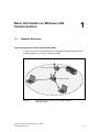
1
SIMATIC NET Operating Instructions SCALANCE W744-1PRO (Client Module) Preface, Contents Basic Information on Wireless LAN Communication 1 Description of the SCALANCE W744 2 Commissioning 3 Configuration with the Primary Setup Tool 4 Configuration Using Web Based Management and the Command Line Interface 5 Technical Specifications 6 Glossary, Index, Certificates and Approvals, Support C79000-G8976-C185-03 Release 01/2005 Classification of Safety-Related Notices This document contains notices which you should observe to ensure your own personal safety, as well as to protect the product and connected equipment. These notices are highlighted in the manual by a warning triangle and are marked as follows according to the level of danger: ! Danger indicates that death or severe personal injury will result if proper precautions are not taken. ! Warning indicates that death or severe personal injury can result if proper precautions are not taken. ! Caution with a warning triangle indicates that minor personal injury can result if proper precautions are not taken. Caution without a warning triangle indicates that damage to property can result if proper precautions are not taken. Notice indicates that an undesirable result or status can occur if the relevant notice is ignored. Note highlights important information on the product, using the product, or part of the documentation that is of particular importance and that will be of benefit to the user. © Copyright Siemens AG, 1998 to 2005 - All rights reserved The reproduction, transmission or use of this document or its contents is not permitted without express written authority. Offenders will be liable for damages. All rights, including rights created by patent grant or registration of a utility model or design, are reserved. Disclaimer We have checked the contents of this manual for agreement with the hardware and software described. Since deviations cannot be precluded entirely, we cannot guarantee full agreement. However, the data in this manual are reviewed regularly and any necessary corrections included in subsequent editions. Suggestions for improvement are welcomed. Siemens AG Automation and Drives Industrial Communication Postfach 4848, D-90327 Nürnberg C79000-G8976-C185-03 Technical data subject to change. Siemens Aktiengesellschaft Printed in the Federal Republic of Germany 2 Trademarks SIMATIC, SIMATIC NET, SINEC, SIMATIC NET Networking for Industry® and SCALANCE® are registered trademarks of Siemens AG. Third parties using for their own purposes any other names in this document which refer to trademarks might infringe upon the rights of the trademark owners. Safety Instructions Regarding your Product Before you use the product described here, read the safety instructions below thoroughly. Qualified Personnel Only qualified personnel should be allowed to install and work on this equipment. Qualified persons are defined as persons who are authorized to commission, to ground, and to tag circuits, equipment, and systems in accordance with established safety practices and standards. Correct Usage of Hardware Products Please note the following regarding the correct usage of hardware products: Caution This device may only be used for the applications described in the catalog or the technical description, and only in connection with devices or components from other manufacturers which have been approved or recommended by Siemens. This product can only function correctly and safely if it is transported, stored, set up, and installed correctly, and operated and maintained as recommended. Before you use the supplied sample programs or programs you have written yourself, make certain that no injury to persons nor damage to equipment can result in your plant or process. Operating Instructions SCALANCE W 744-1PRO C79000-G8976-C185-03 3 Correct Usage of Software Products Please note the following regarding the correct usage of software products: Caution This software may only be used for the applications described in the catalog or the technical description, and only in connection with software products, devices, or components from other manufacturers which have been approved or recommended by Siemens. Before you use the supplied sample programs or programs you have written yourself, make certain that no injury to persons nor damage to equipment can result in your plant or process. Prior to Startup Before putting the product into operation, note the following warning: Caution Prior to startup you must observe the instructions in the relevant documentation. For ordering data of the documentation please refer to the catalogs or contact your local SIEMENS representative. 4 Operating Instructions SCALANCE W 744-1PRO C79000-G8976-C185-03 Preface Scope of this Manual This manual describes the products SCALANCE W744-1PRO. This manual applies to the following software versions: ● SCALANCE W744 firmware as of Version 1.0 ● Primary Setup Tool as of Version 2.0.10 Purpose of the Manual This manual is intended to provide you with the information you require to install, commission and operate the SCALANCE W744 correctly. It explains how to configure the SCALANCE W744 and how to integrate the SCALANCE W744 in a WLAN network. Operating Instructions SCALANCE W 744-1PRO C79000-G8976-C185-03 5 Preface Orientation in the Documentation Apart from the operating instructions you are currently reading, the following documentation is also available from SIMATIC NET on the topic of Industrial Wireless LANs: ● Operating Instructions (compact) SCALANCE W744-1PRO This document is supplied on paper with the device and contains an abridged version of the most important information required to work with the SCALANCE W744. ● System Manual Wireless LAN Basics This includes not only the description of the physical basics and an outline of the most important IEEE standards but also information on data security and a description of industrial uses of wireless LAN. You should read this manual if you want to set up WLAN networks with a more complex structure (not only connections between two devices). ● Operating Instructions SCALANCE W788-1PRO / SCALANCE W788-2PRO This is the comprehensive user documentation on the SCALANCE W788-1PRO with all the information required for installation, commissioning and operation of this device. The SCALANCE W788-1PRO is connected to a PC / PLC by an Ethernet cable and allows the attachment of these devices to a wireless network; in other words, it is a gateway from a wired to a wireless network. ● Operating Instructions (compact) SCALANCE W788-1PRO This document is supplied on paper with the device and contains an abridged version of the most important information required to work with the SCALANCE W788-1PRO. ● Operating Instructions CP 7515 The comprehensive user documentation for the CP 7515 communications processor with all the information required to operate this device. The CP 7515 is inserted in a CardBus / PC-card (32-bit) slot and allows attachment of the PC/PG to a wireless network. ● Operating Instructions (compact) CP 7515 This document is supplied with the device on paper and contains a concise summary of the most important information required to use the CP 7515. ● Manual CP 1515 The comprehensive user documentation for the CP 1515 communications processor with all the information required to operate this device. The CP 1515 is inserted in a PC-card slot (Type II) and allows attachment of the PC/PG to a wireless network. 6 Operating Instructions SCALANCE W 744-1PRO C79000-G8976-C185-03 Preface Biological Compatibility With regard to the question of whether electromagnetic fields (for example in association with industrial wireless LANs) can put human health at risk, we refer to a publication of BITKOM (German Association for information Technology, Telecommunication and New Media e. V) dated December 2003: "The same regulations for the protection of health for all other radio applications also apply to WLAN devices. These regulations are based on the protection concept of ICNIRP2 or the corresponding recommendation of the European Council. The independent German radiation protection commission (SSK) was commissioned by the federal German ministry of the environment to investigate the possible dangers - thermal and non-thermal - resulting from electromagnetic fields and came to the following conclusions3: "The SSK comes to the conclusion that even after evaluation of the latest scientific literature, there is no new scientific evidence regarding proven adverse effects on health that causes any doubt regarding the scientific evaluation on which the protection concept of the ICNIRP or the European Council recommendation is based." The SSK also concludes that below the current limit values, there is also no scientific suspicion of health risks. This evaluation agrees with that of other national and international scientific commissions and with that of the WHO (www.who.int/emf). [...] [...] 2 3 International Council on Non-Ionizing Radiation Protection Limit Values and Precautionary Measures to Protect the General Public from Electromagnetic Fields, Issue 29, 2001. You will find further information on this topic under the following URL: www.bitkom.org Operating Instructions SCALANCE W 744-1PRO C79000-G8976-C185-03 7 Preface 8 Operating Instructions SCALANCE W 744-1PRO C79000-G8976-C185-03 Contents 1 Basic Information on Wireless LAN Communication ............................................... 11 1.1 Network Structure .............................................................................................. 11 2 Description of the SCALANCE W744 ......................................................................... 13 3 Commissioning............................................................................................................. 19 3.1 Lightning Protection, Power Supply and Grounding ......................................... 19 3.2 Assembly and Connectors................................................................................. 21 3.3 3.3.1 3.3.2 3.3.3 Cabling for Power Supply and Ethernet ............................................................ 23 General Notes.................................................................................................... 23 Assembling IE Hybrid Cable 2x2 + 4x0,34 with an IE IP67 Hybrid Connector . 24 Assembling IE FC TP Standard Cable 4x2 GP or IE FC TP Flexible Cable 4x2 GP with an IE IP67 Hybrid Connector ............................................................... 28 Pinout of the M12 Connector............................................................................. 31 3.3.4 4 5 Configuration with the Primary Setup Tool ............................................................... 33 4.1 Introduction ........................................................................................................ 33 4.2 Installing the DLC Protocol ................................................................................ 35 4.3 Installing the Primary Setup Tool....................................................................... 36 4.4 Working with the Primary Setup Tool ................................................................ 36 4.5 Primary Setup Tool via the Command Line....................................................... 40 Configuration Using Web Based Management and the Command Line Interface 41 5.1 5.1.1 5.1.2 5.1.3 5.1.4 General Information on Web Based Management and the Command Line Interface............................................................................................................. 41 Introduction ........................................................................................................ 41 The LED Simulation of Web Based Management............................................. 42 Working with Web Based Management ............................................................ 43 Command Line Interface ................................................................................... 44 5.2 5.2.1 5.2.2 5.2.3 5.2.4 5.2.5 5.2.6 5.2.7 5.2.8 5.2.9 5.2.10 5.2.11 The System Menu.............................................................................................. 46 System Information Menu Command ................................................................ 46 IP Settings Menu Command.............................................................................. 47 Services Menu Command ................................................................................. 48 Restart Menu Command ................................................................................... 49 Event Config Menu Command .......................................................................... 51 E-mail Config Menu Command ......................................................................... 52 SNMP Config Menu Command ......................................................................... 53 SNTP Config Menu Command .......................................................................... 56 Fault State Menu Command.............................................................................. 57 Load & Save Menu Command .......................................................................... 57 C-PLUG Menu Command ................................................................................. 60 5.3 5.3.1 5.3.2 The Interfaces Menu.......................................................................................... 62 Ethernet Menu Command ................................................................................. 62 WLAN Menu Command..................................................................................... 63 Operating Instructions SCALANCE W 744-1PRO C79000-G8976-C185-03 9 Contents 6 5.3.3 5.3.4 5.3.5 Advanced Submenu .......................................................................................... 65 SSID List Submenu Command.......................................................................... 68 Advanced G Submenu ...................................................................................... 69 5.4 5.4.1 5.4.2 5.4.3 The Security Menu............................................................................................. 71 Basic Wireless Menu Command ....................................................................... 71 Keys Menu Command ....................................................................................... 73 Access Menu Command ................................................................................... 74 5.5 5.5.1 5.5.2 The Bridge Menu ............................................................................................... 75 Learning Table Menu Command ....................................................................... 76 ARP Table Menu Command.............................................................................. 76 5.6 5.6.1 5.6.2 5.6.3 5.6.4 5.6.5 5.6.6 5.6.7 The Information Menu ....................................................................................... 77 Log Table Menu Command ............................................................................... 77 Auth Log Menu Command................................................................................. 78 Versions Menu Command ................................................................................. 78 Available WLAN Menu Command ..................................................................... 79 Ethernet Menu Command ................................................................................. 80 WLAN Menu Command..................................................................................... 80 IP, TCP/IP, ICMP, SNMP Menu Command....................................................... 81 Technical Specifications ............................................................................................. 83 Approvals ................................................................................................................................... 87 Appendix Private MIB Variables of the SCALANCE W744................................................. 93 Glossary ..................................................................................................................................... 97 Index 10 ...................................................................................................................................... 101 Operating Instructions SCALANCE W 744-1PRO C79000-G8976-C185-03 Basic Information on Wireless LAN Communication 1.1 1 Network Structure Typical Configuration with the SCALANCE W744 A typical use of the SCALANCE W744 is to integrate wired Ethernet devices (for example SIMATIC S7-PLCs) in a wireless network. S C A L A N C E W 7 4 4 S C A L A N C E W 7 8 8 Figure 1-1 Interfacing a SIMATIC S7-PLC to a Wireless LAN with a SCALANCE W744. Operating Instructions SCALANCE W 744-1PRO C79000-G8976-C185-03 11 Basic Information on Wireless LAN Communication 12 Operating Instructions SCALANCE W 744-1PRO C79000-G8976-C185-03 Description of the SCALANCE W744 2 Components of the Product The following components are supplied with the SCALANCE W744: ● SCALANCE W744-1PRO ● 2 OMNI antennas ● 1 IE IP67hybrid connector ● 1 dummy plug for the M12 socket ● 2 dummy plugs for the R-SMA sockets ● 1 SIMATIC NET Industrial Wireless LAN CD with these Operating Instructions for the SCALANCE W744 Please check that the consignment you have received is complete. If it is not complete, please contact your supplier or your local Siemens office. Requirements for Installation and Operation To configure the SCALANCE W744, a PG/PC with network attachment must be available. If no DHCP server is available, a PC on which the Primary Setup Tool (PST) is installed is necessary for the initial assignment of an IP address to the SCALANCE W744. For the other configuration settings, a computer with Telnet or an Internet browser is necessary. Operating Instructions SCALANCE W 744-1PRO C79000-G8976-C185-03 13 Description of the SCALANCE W744 Possible Applications of the SCALANCE W744 The SCALANCE W744 is equipped with an Ethernet interface and a wireless LAN interface (SCALANCE W744-2PRO: two WLAN interfaces). This makes the device suitable for the following applications: ● The SCALANCE W744 can be used as a connection between a device with ethernet interface (i. e. SIMATIC PLC with industrial ethernet communication processor) and a wireless network. ● The SCALANCE W744 can be used as a gateway from a wired to a wireless network. One node is supported in the wired network. Properties of the SCALANCE W744 ● The Ethernet interface supports 10 Mbps and 100 Mbps, both in full and half duplex as well as autocrossing and autonegotiation. ● The wireless interface is compatible with the IEEE 802.11a, IEEE 802.11b, and IEEE 802.11g standards. In the 802.1a- and 802.1g mode, the total transmission rate is up to 54 Mbps. In the turbo mode, the transmission rate is up to 108 Mbps (not permitted in all countries and modes). ● Operation in the 2.4 GHz and 5 GHz frequency bands. ● Support of the authentication standards WPA, WPA-PSK and IEEE 802.1x and WEP, AES and TKIP encryption schemes. ● Suitable for inclusion of a RADIUS server for authentication. ● The interoperability of SCALANCE W744 devices with WiFi devices of other vendors was tested thoroughly. Ports The SCALANCE W744 has the following ports: ● RJ45 hybrid connector on the front panel of the housing consisting of an RJ-45 jack and 4-pin power socket. The RJ-45 connector supports the use of switches capable of power-over-Ethernet according to 802.3af. The 4-pin power socket allows power of 24-48 VDC to be supplied. ● An M12 connector as optional power supply.(24-48 VDC) ● Two R-SMA plugs (four R-SMA plugs on the SCALANCE W744-2PRO) for the attachment of antennas on the sides of the device. 14 Operating Instructions SCALANCE W 744-1PRO C79000-G8976-C185-03 Description of the SCALANCE W744 LED Display L 1 Figure 2-1 F L 2 P 1 R 1 On the front of the housing, several LEDs provide information on the operating status of the SCALANCE W744: The LEDs of the SCALANCE W744 The LEDs have the following significance: LED P1 Color Meaning Yellow Data transfer over the Ethernet interface (traffic). Green There is a connection over the Ethernet interface. (Link) L2 Green Power supply over hybrid connector X1. (PoE or power contacts) R1 Yellow Data transfer over the WLAN interface. Green There is a connection over the WLAN interface to an AP or ad hoc network. Green flashing The client is searching for a connection to an access point or ad hoc network. Green flashing quickly The client is waiting for the adopt MAC address. Only in Auto Adopt mode. L1 Green Power supply over the M12 connector. (X2) F Red An error occurred during operation with the SCALANCE W744. Operating Instructions SCALANCE W 744-1PRO C79000-G8976-C185-03 15 Description of the SCALANCE W744 Notice If the LED for the WLAN interface does not light up green during startup although it is activated, then initialization of the interface was unsuccessful. This can occur, in particular, when the operating temperature has not yet been reached. If the SCALANCE W 700 products are started up in negative temperatures, waiting times of up to 15 minutes are possible. Configuration Information on the C-PLUG The C-PLUG is used to transfer the configuration of the old device to the new device when a device is replaced. When the new device starts up, it continues with exactly the same configuration as the old device. One exception to this can be the IP configuration if it is set over DHCP and the DHCP server has not been reconfigured accordingly. Replacing the C-PLUG Follow the steps below to replace a C-PLUG in a SCALANCE W744: 1. Remove the old SCALANCE W744 from its mounting and open the sealing screw on the rear with a coin or broad screwdriver. 2. Remove the C-PLUG. 3. Open the sealing screw of the new device in the same way and insert the CPLUG of the old device. 4. Replace the sealing screws of both devices. If a new C-PLUG is inserted in a SCALANCE W744-1PRO, the configuration stored locally on the SCALANCE W744-1PRO is saved to the C-PLUG. If an incorrect C-PLUG (for example from another device or a damaged plug) is inserted, the SCALANCE W744 signals an error with the red LED. The user then has the choice of either removing the C-PLUG again or selecting the option to reformat the CPLUG and use it. 16 Operating Instructions SCALANCE W 744-1PRO C79000-G8976-C185-03 Description of the SCALANCE W744 Reset Button The reset button is located directly beside the C-PLUG and has several functions: ● Restarting the device. To restart the device, press the Reset button. ● Downloading new firmware (if the normal procedure for downloading firmware does not work) Follow the steps below to download new firmware: 1. Turn off the power to the device. 2. Now press the Reset button and reconnect the power to the device while holding down the button. 3. Hold down the button until the red fault LED (F) starts to flash after approximately 2 seconds. 4. Now release the button. The bootloader waits in this state for a new firmware file that you can download by FTP. 5. Assign an IP address with the Primary Setup Tool. 6. Connect a PC to the SCALANCE W744 over the Ethernet interface. 7. Assign an IP address with the Primary Setup Tool. 8. Then enter the command "ftp <ip address>“ in a DOS box or use a different FTP client. The new firmware should be located in the same folder as the DOS box. 9. For the login and password, enter "siemens“. You can now transfer the new firmware with the "put <firmware>“ command. ● Restoring the default parameters (factory default) Caution: All previously made settings are lost! First, turn off the power to the device. Then press the Reset button and reconnect the power to the device while holding down the button. Hold down the button until the red fault LED (F) stops flashing after approximately 10 seconds and is permanently lit. Now release the button and wait until the error LED (F) goes off. The device now starts automatically with the default parameters. Operating Instructions SCALANCE W 744-1PRO C79000-G8976-C185-03 17 Description of the SCALANCE W744 18 Operating Instructions SCALANCE W 744-1PRO C79000-G8976-C185-03 Commissioning 3.1 3 Lightning Protection, Power Supply and Grounding Notes on Lightning Protection ! Warning Antennas installed outdoors must be within the area covered by a lightning protection system. Make sure that all conducting systems entering from outdoors can be protected by a lightning protection potential equalization system. When implementing your lightning protection concept, make sure you adhere to the VDE 0182 or IEC 62305 standard. A suitable lightning conductor is available in the range of accessories of SIMATIC NET Industrial WLAN: Lightning Protector LP798-1PRO (order no. 6GK5798-1LP00-0AA6) Operating Instructions SCALANCE W 744-1PRO C79000-G8976-C185-03 19 Commissioning Notes on Power Supply and Grounding ! Warning The SCALANCE W744-1PRO device is designed for operation with safety extralow voltage (SELV). This means that only safety extra-low voltages (SELV) with limited power source (LPS) complying with IEC950/EN60950/ VDE0805 can be connected to the power supply terminals. The power supply unit to supply the SCALANCE W744 must comply with NEC Class 2 (voltage range 18 - 32 V, current requirement 1 A) The subject unit is to be supplied by a Class 2 power source complying with the requirements of the National Electrical Code, table 11 (b). If power is redundant supplied (two individual power sources) the power sources together should comply with the requirements of the National Electrical Code, table 11 (b). Exceptions: Power supply with PELV (according to VDE 0100-410) is also possible if the generated rated voltage does not exceed the voltage limits 25 V AC or 60 V DC. Power supply by a SELV power source (according to IEC 60950) or PELV power source (according to VDE 0100-410) without limited power is also permitted if suitable fire protection measures are taken by: - Installation in a cabinet or suitable enclosure - Installation is a suitably equipped, closed room Caution There must be no potential difference between the following parts, otherwise there is a risk that the device could be destroyed: • Ground potential of the power supply and the ground potential of the antenna ground. • Ground potential of the power supply and a grounded enclosure. • Ground potential of the power supply and the ground potential of the device connected to Industrial Ethernet (for example, PC, AS-300, AS-400 etc.). Connect both grounds to the same foundation earth or use an equipotential bonding conductor. 20 Operating Instructions SCALANCE W 744-1PRO C79000-G8976-C185-03 Commissioning 3.2 Assembly and Connectors Securing the Housing There are two ways of securing the housing: ● Use the holes in the housing to screw the device to the wall or on a horizontal surface. ● Install the SCALANCE W788 on a 90 mm long, vertically mounted piece of standard rail (S7-300). In this case, the standard rail serves as an adapter between the wall and SCALANCE W788. If you want to install the SCALANCE W788 along with a PS791-1PRO, a 150 mm long standard rail is necessary. Connectors for the Power Supply and for Ethernet The SCALANCE W788 is attached to Ethernet via a hybrid socket on the front of the housing (position A in Figure 3.1). This port also has contacts for the operating voltage. Note If you do not use the hybrid socket, this must be covered with a protective cap, otherwise IP65 protection is lost. A suitable protective cap is available as an accessory. If you do not use the M12 connector, the supplied protective cap must be fitted to retain IP65 protection. D A B Figure 3-1 C Connectors of the SCALANCE W744 Operating Instructions SCALANCE W 744-1PRO C79000-G8976-C185-03 21 Commissioning As an alternative or in addition to this, you can also use the M12 plug for the power supply (position B in Figure 3.1). You can screw the supplied antennas onto the R-SMA connectors on the sides of the housing (position C in Figure 3.1). As an alternative you can use separate antennas installed at a distance from the device. 22 Operating Instructions SCALANCE W 744-1PRO C79000-G8976-C185-03 Commissioning 3.3 Cabling for Power Supply and Ethernet 3.3.1 General Notes Suitable Cables The following cable variants are available to connect a SCALANCE W-700 to the power supply and to Ethernet: ● IE hybrid cable 2x2 + 4x0,34 (order no. 6XV1870-2J) The two data wire pairs are separately shielded. This cable is particularly suitable for assembly with the IE IP67 hybrid connector. ● IE FC TP standard cable 4x2 GP (order no. 6XV1870-2E) IE FC TP flexible cable 4x2 GP (order no. 6XV1870-2H) In these cable types, two wires are twisted. All for pairs of wires are inside a common shield. Cable Selection and Interference Exposure A decisive factor in the selection of a cable type is the electromagnetic interference to which the current lines between the power supply and the FC RJ-45 modular outlet are subjected. Due to the separate shielding of the data wires, such interference has less effect on the data transmission on a hybrid cable than on TP standard cable or TP flexible cable. A Figure 3-2 B C Cabling a SCALANCE W700 with electromagnetic interference injection between the power supply and modular outlet A Power supply B FC RJ-45 modular outlet with power insert C SCALANCE 788 / 744 Operating Instructions SCALANCE W 744-1PRO C79000-G8976-C185-03 23 Commissioning 3.3.2 Assembling IE Hybrid Cable 2x2 + 4x0,34 with an IE IP67 Hybrid Connector Remove the two inner shells of the universal sealing ring to adapt it to the diameter of the hybrid cable. Push the bushing, washer, adapted universal sealing ring and the housing over the cable jacket. Remove the following lengths of cable jacket and shield braid: 25 mm for the power leads. 30 mm jacket for the data leads (shorten the braid by 11 mm). Cut off the filler at the height of the cable jacket. Arrange the data leads according to the color codes on the splice element. The following table shows the assignment of the data leads. Contact and color assignment of the splice element. 24 Operating Instructions SCALANCE W 744-1PRO C79000-G8976-C185-03 Commissioning Wire color code (standard) white Blue Yellow Orange Connector color code (Siemens IE) White Blue Yellow Orange Siemens IE FC RJ-45 socket (reference) 3 6 1 2 Insert the all the data leads at the same time into the spice element is far as they will go. Close the splice element and RJ-45 data module until they lock together. Insert the data module and the spice element into the supplied IDC assembly tool. Press the data module and the IDC assembly tool together to establish the installation piercing connection. Operating Instructions SCALANCE W 744-1PRO C79000-G8976-C185-03 25 Commissioning Remove the assembled data module from the IDC assembly tool. Position the top shield plate and press it over the cable shield. Position the lower shield place and press it and the upper shield plate together until they lock together with an audible "click". Arrange the power leads and insert them as far as they will go into the hinge elements of the isolation body. The following table shows the assignment of the power leads. Wire color code (standard) Power supply insert module 26 Brown Brown Black Black 24 V 24 V Ground Ground 1 2 3 4 Operating Instructions SCALANCE W 744-1PRO C79000-G8976-C185-03 Commissioning Press each individual hinge element together with the integrated IDC contact. Recommendation: Use a small slotted screwdriver (max. 3.5 mm) as a lever. Push the housing over the assembled data module and the insulator body until they lock together (there should be an audible click). Tighten the cable gland. We recommend an open ring key with a size of 21 mm. Operating Instructions SCALANCE W 744-1PRO C79000-G8976-C185-03 27 Commissioning 3.3.3 Assembling IE FC TP Standard Cable 4x2 GP or IE FC TP Flexible Cable 4x2 GP with an IE IP67 Hybrid Connector Remove the two inner shells of the universal sealing ring to adapt it to the diameter of the hybrid cable. Push the bushing, washer, adapted universal sealing ring and the housing over the cable jacket. Remove the following lengths of cable jacket and shield braid: 25 mm for the power leads. 30 mm for the data leads (to achieve good shielding, the shield braid should be at least 30 mm long). Arrange the data leads according to the color codes on the splice element. The following table shows the assignment of the data leads. Wind the shield braid around the data leads. As a result, the shielding of the cable has contact to the shield plate of the splice element that will be fitted later. Contact and color assignment of the splice element. 28 Operating Instructions SCALANCE W 744-1PRO C79000-G8976-C185-03 Commissioning Color Coding of the Standard Cable White / orange * Orange White / Green * Green Connector color code (Siemens IE) White Blue Yellow Orange Siemens IE FC RJ-45 socket (reference) 3 6 1 2 * White wire of the particular pair. Insert the all the data leads at the same time into the spice element is far as they will go. Close the splice element and RJ-45 data module until they lock together. Insert the data module and the spice element into the supplied IDC assembly tool. Press the data module and the IDC assembly tool together to establish the installation piercing connection. Operating Instructions SCALANCE W 744-1PRO C79000-G8976-C185-03 29 Commissioning Remove the assembled data module from the IDC assembly tool. Position the top shield plate and press it over the cable shield. Position the lower shield place and press it and the upper shield plate together until they lock together with an audible "click". Arrange the power leads and insert them as far as they will go into the hinge elements of the isolation body. The following table shows the assignment of the power leads. Wire color code (standard) Power supply insert module 30 White / Blue * Blue White brown * Brown 24 V 24 V Ground Ground 1 2 3 4 Operating Instructions SCALANCE W 744-1PRO C79000-G8976-C185-03 Commissioning Press each individual hinge element together with the integrated IDC contact. Recommendation: Use a small slotted screwdriver (max. 3.5 mm) as a lever. Push the housing over the assembled data module and the insulator body until they lock together (there should be an audible click). Tighten the cable gland. We recommend an open ring key with a size of 21 mm. 3.3.4 Pinout of the M12 Connector X2 Socket PIN 1 24 V DC PIN 2 -- PIN 3 Ground PIN 4 -- Operating Instructions SCALANCE W 744-1PRO C79000-G8976-C185-03 31 Commissioning 32 Operating Instructions SCALANCE W 744-1PRO C79000-G8976-C185-03 Configuration with the Primary Setup Tool 4.1 4 Introduction Initial Assignment of an IP Address An initial IP address for the SCALANCE W744 cannot be assigned using Web Based Management or the Command Line Interface because these configuration tools require that an IP address already exists. The initial IP address can be obtained only over DHCP or assigned using the Primary Setup Tool. The Primary Setup Tool is capable of assigning such an address to unconfigured devices without an IP address. The only condition is that the devices can be reached over Ethernet. Operating Systems Supported The Primary Setup Tool can be installed and used with the following operating systems: ● Windows XP Professional ● Windows 2000 Professional SP2 DLC Protocol The Primary Setup Tool uses the DLC protocol for communication with the modules. This protocol is not supplied with Windows XP and must be installed extra for this operating system. Follow the steps below to check whether or not the DLC protocol exists on your computer: 1. Select the menu command Start > Settings > Control Panel >Network and Dial-Up Connections. 2. Select the connection to your Ethernet communication module. Operating Instructions SCALANCE W 744-1PRO C79000-G8976-C185-03 33 Configuration with the Primary Setup Tool 3. Right-click to open the context menu and select Properties. The General tab lists all protocols and services. The DLC protocol should be listed and selected: If the DLC protocol is listed, you can skip to the next but one section "Installing the Primary Setup Tool". If there is no entry for the DLC protocol, install it as described in the next section. 34 Operating Instructions SCALANCE W 744-1PRO C79000-G8976-C185-03 Configuration with the Primary Setup Tool 4.2 Installing the DLC Protocol Extracting the Archive File The files for installing the DLC protocol are in the self-extracting ZIP archive pst_xp_install.exe. Follow the steps below to extract the files from the archive: 1. Double-click on the file name pst_xp_install.exe in the Windows Explorer or start the program using the Windows menu command Start > Run. 2. In the dialog box of the extraction program, select the folder into which you want to extract the files and click on the Unzip button. Installation Follow the steps below to install the DLC protocol on your computer: 1. Select the menu command Start > Settings > Control Panel >Network and Dial-Up Connections. 2. Select the connection to your Ethernet communication module. 3. Right-click to open the context menu and select Properties. 4. Click on the Install... button in the General tab. 5. In the Select Network Component Type dialog, select the entry Protocol and click the Add... button. 6. In the Network Protocol dialog, click the Have Disk... button. 7. In the Install from Disk dialog, click the Browse... button. 8. In the file list box, change to the folder with the extracted installation files, select the netdlc.inf file and click the Open button. 9. In the Install from Disk dialog, click OK. The protocol is installed; the list box in the properties dialog of the communication module now includes the entry DLC Protocol (Windows 2000/XP) for Siemens Primary Setup Tool. 10. Close the properties dialog by clicking the OK button. Operating Instructions SCALANCE W 744-1PRO C79000-G8976-C185-03 35 Configuration with the Primary Setup Tool 4.3 Installing the Primary Setup Tool Procedure The files of the Primary Setup Tools are in the self-extracting ZIP archive pst_install.exe. Follow the steps below to install the files of the archive: 4.4 1. Double-click on the file name pst_install.exe in the Windows Explorer or start the program using the Windows menu command Start > Run. 2. In the dialog box of the extraction program, select the folder into which you want to extract the files; the default is c:\siemens\pst. 3. Click the Unzip button. After extraction, the folder you selected contains several files including s7wnpstx.exe. Start the Primary Setup Tool by doubleclicking on this file. Working with the Primary Setup Tool Selecting the Language After starting the Primary Setup Tool, a dialog opens in which you select the language for the program. You can also set the language in the Settings > Language menu. Selecting the Network Adapter If there is more than one network adapter in your computer, you can open the Settings > Network Adapter menu and specify which adapter is used by the Primary Setup Tool. This menu displays a maximum of four network adapters, however only those for which the DLC protocol is activated are shown. 36 Operating Instructions SCALANCE W 744-1PRO C79000-G8976-C185-03 Configuration with the Primary Setup Tool Browsing the Network Before you assign IP addresses with the PST, you must first locate the configurable devices in the network. Start this search with the steps outlined below: ● Select the Network > Browse menu command. ● Click on the magnifier icon in the toolbar below the menu bar. While the Primary Setup Tool browses the network, the Browse Network dialog is displayed with a progress bar. On completion of the search, the Primary Setup Tool displays a list with all the devices it has found in the left-hand pane. Configuring a Module If you click an entry in the list, the Primary Setup Tool displays information on the selected device in the right-hand pane. Follow the steps below to configure a device: 1. Click on the plus symbol in front of the device symbol or double-click on the device symbol to display all interfaces of the device. 2. Click on the interface you want to configure. The Primary Setup Tool displays the input dialog for the configuration data in the right-hand pane of the program window. Depending on the selected settings, some text boxes or check boxes may be disabled. The MAC address box is always disabled because this address is a property of the device that cannot be modified. The Client ID parameter and DNS is also not supported by the SCALANCE W744. Operating Instructions SCALANCE W 744-1PRO C79000-G8976-C185-03 37 Configuration with the Primary Setup Tool 3. Decide how the device will obtain its IP address: ● Dynamically from a DHCP server: Select the Obtain IP address from DHCP server option button. ● Manual assignment by the user: Select the Assign IP parameters option button. 4. Make the following entries if you have decided to assign the IP address manually: ● Enter the IP address for the device in the IP Address box. In each part of the address separated by the periods, you can enter a number between 0 and 255; the program does not accept any other numbers. ● Enter the subnet mask in the Subnet Mask box. ● If necessary, select the Use router check box and enter the IP address of the router in the text box. Router information is necessary if the computer on which you are creating the configuration is not in the same subnet as the SCALANCE W744. Downloading to the Module Follow the steps below to transfer the configuration data to the device: 1. Select the module to which you will download the configuration data in the lefthand pane of the program window. As long as an interface is selected and the input dialog for the configuration data is displayed, no download is possible. 2. Start the download with the steps outlined below: ● Select the Module > Download menu command. ● Click the second icon from the left in the toolbar (S7 modules with yellow arrow). 38 Operating Instructions SCALANCE W 744-1PRO C79000-G8976-C185-03 Configuration with the Primary Setup Tool Starting Web Based Management INCs (Industrial Network Components) such as the SCALANCE W744 include Web Based Management. Select the device you want to configure with Web Based Management and follow the steps below to start Web Based Management: ● Select the menu command Module -> Start INC Browser. ● Click on the third icon from the left in the toolbar (module with four blue wires). If the Module > Start INC Browser and the module icon are disabled, there is no Web Based Management for the selected module. Removing a Module You can remove a module from the list in the left-hand part of the program window by selecting the Module > Remove Module menu command. Using this menu command has no effect on the existence of a module in the network; if you browse the network again, all modules are displayed again. Operating Instructions SCALANCE W 744-1PRO C79000-G8976-C185-03 39 Configuration with the Primary Setup Tool 4.5 Primary Setup Tool via the Command Line Syntax You can also use the Primary Setup Tool from the command line of a DOS prompt. The syntax is as follows; optional parameters are shown in square brackets: s7wnpstx MAC address -DHCP[=client ID] s7wnpstx MAC address -RESET s7wnpstx MAC address IP address subnet mask [router address] The following table explains the parameters: Command Description MAC address The MAC address of the module to be configured. -DHCP Specifies that the IP address is obtained from a DHCP server. client ID A unique identifier for the device. If this parameter is not specified, the Primary Setup Tool uses the MAC address as the ID. -RESET IP address Sets the IP address to 0.0.0.0 . subnet mask The new subnet mask of the module to be configured. Router address The new IP address of the default router. 40 Comment Optional. The new IP address of the module to be configured. Optional. Operating Instructions SCALANCE W 744-1PRO C79000-G8976-C185-03 Configuration Using Web Based Management and the Command Line Interface 5 5.1 General Information on Web Based Management and the Command Line Interface 5.1.1 Introduction Contents of this Chapter This chapter explains the possible settings for the SCALANCE W788. For a detailed description of the individual elements of a page, refer to the online help. As an alternative, you can also configure the device using the Command Line Interface (CLI). This allows remote configuration over Telnet. This chapter describes both configuration methods together because the menu structure of Web Based Management is the same as the structure of the CLI commands. Note You should only use the command line interface if you are an experienced user. Even commands that bring about fundamental changes to the configuration are normally executed without a prompt for confirmation Operating Instructions SCALANCE W 744-1PRO C79000-G8976-C185-03 41 Configuration Using Web Based Management and the Command Line Interface Note on User Login If you log on as user, you will only have restricted use of WEB and Telnet. Since you only have read access, some commands do not exist in Telnet and some areas cannot be selected. Required Experience To be able to use the information in this chapter effectively, you should have a thorough knowledge of network technology and WLANs. 5.1.2 The LED Simulation of Web Based Management Display of the Operating State The SCALANCE W744 has one or more LEDs that provide information on the operating state of the device (see Chapter 2). Depending on its location, direct access to the SCALANCE W744 may not always be possible. Web Based Management therefore displays simulated LEDs. Activating the Simulation There is an HTML-based simulation of the LED status. Click on the green icon below the Console link to activate the simulation: 42 Operating Instructions SCALANCE W 744-1PRO C79000-G8976-C185-03 Configuration Using Web Based Management and the Command Line Interface 5.1.3 Working with Web Based Management Navigation Bar The upper menu bar of WBM contains the following links: ● Console This link opens a console window in which you can enter CLI commands. ● Support When you click this link, you open a SIEMENS AG support page. ● Logout Close the current Web Based Management session by clicking on this link. The logon dialog is then displayed again. ● Help Clicking on this link opens the online help of Web Based Managements in a separate browser window. Updating the Display with Refresh Web Based Management pages have a Refresh button at the lower edge of the page. Click this button to request up-to-date information from the SCALANCE W744. Saving Entries with Set Values Pages in which you can make configuration settings have a Set Value button at the lower edge. Click this button to save the configuration data you have entered on the SCALANCE W744. Creating entries with NEW Pages in which you can create lists have the New button at the lower edge. Click this button to save the configuration data you have entered on the SCALANCE W744. Recessing Encounter with Reset Statistics With this button, you can reset the relevant counters. Operating Instructions SCALANCE W 744-1PRO C79000-G8976-C185-03 43 Configuration Using Web Based Management and the Command Line Interface 5.1.4 Command Line Interface Starting the CLI in a Windows Console Follow the steps outlined below to start the Command Line Interface in a Windows console: 1. Open a Windows console and type in the command telnet followed by the IP address of the SCALANCE W744: C:\>telnet <IP address> 2. Enter your login and password. As an alternative, you can also enter the command telnet followed by the IP address of the SCALANCE W744 in the Start > Execute menu. Starting the CLI in Web Based Management Click on the Console entry in the upper menu bar of Web Based Management. A console opens in which you can log on with your login and password. The IP address is adopted by Web Based Management. Shortcuts for Commands As an alternative, instead of entering full CLI commands, you can simply enter the first letter or the first few letters of the command and then press the Tab key. The Command Line Interface then displays a command starting with the letter or letters you typed in. If the command displayed is not the command you require, press the Tab key again to display the next command. Directory Structure Before you can enter a command in the Command Line Interface, you must first open the required menu or submenu. This section lists the commands of each menu in a separate table. The menu itself is shown above the table on a gray background. The table lists only the commands themselves. 44 Operating Instructions SCALANCE W 744-1PRO C79000-G8976-C185-03 Configuration Using Web Based Management and the Command Line Interface Symbols for Representing CLI Commands CLI commands generally have one or more parameters that are represented in the syntax description as follows: ● Mandatory parameters are shown in pointed brackets. Example: <IP address> ● Optional parameters are shown in square brackets. Example: [E|D] If you omit an optional parameter, most commands output the currently set value. ● Alternative input values are separated by the pipe character. In this case, you specify one of the listed values as the parameter. Example: [E|D] You must enter either E or D. ● If a numeric value is required as a mandatory parameter, you can also specify a range of values: Example: <0 ... 255> You must enter a value between 0 and 255. Cross-menu Commands You can use the commands in the following table in any menu. CLI\ ... > Command Description Comment / Moves you one menu level higher. ? Displays the commands and submenus available in the menu. exit Closes the CLI/TELNET session. Cannot be called using the command shortcuts. trace [Mod] [+|-][Level] Enables / disables the trace function. For troubleshooting IQoS, errors, and statistics restart Restarts the SCALANCE W744 Cannot be called using the command shortcuts. info Displays information on the current menu item. Operating Instructions SCALANCE W 744-1PRO C79000-G8976-C185-03 45 Configuration Using Web Based Management and the Command Line Interface 5.2 The System Menu 5.2.1 System Information Menu Command Mode and Locale Setting On this page, you make several basic settings for the SCALANCE W744, for example, the country and mode for the device. Syntax of the Command Line Interface CLI\SYSTEM> Command Description Comment country [AT|AU|BE|CA|CH| CL|CZ|DE|DK|ES|FI|FR|GB| GR|HK|HU|IE|IS|IT|JP|KR| KW|LI|LU|NL|NO|PT|SE|SG| TR| US|ZA] Specifies properties for specific countries. The country codes comply with ISO 3166, however the SCALANCE W744 supports only the codes listed in the left-hand column. This command is not available in the version for USA / Canada. AT AU BE CA CH CL CZ DE DK ES FI FR GB GR HK HU IE IS IT JP KR KW LI LU NL NO PT SE SG TR US ZA 46 Austria Australia Belgium Canada Switzerland Chile Czech Republic Germany Denmark Spain Finland France Great Britain Greece Hong Kong Hungary Ireland Iceland Italy Japan Korea Kuwait Lichtenstein Luxembourg Netherlands Norway Portugal Sweden Singapore Turkey United States of America South Africa Operating Instructions SCALANCE W 744-1PRO C79000-G8976-C185-03 Configuration Using Web Based Management and the Command Line Interface Command Description Comment name [device name] Assigns a value to the sysName MIB variable. Maximum of 255 characters. If you want to use the name in WDS or redundancy, the maximum length is 32 characters. location [location] Assigns a value to the sysLocation MIB variable. Maximum of 255 characters. contact [name] Assigns a value to the sysContact MIB variable. Maximum of 255 characters. ping [-c N] <IP Address|name> For connection test to partner. Telnet only password [admin|user] [password] Specifies a password for access to the SCALANCE W744. 5.2.2 -c (counter) for the number of IGMPs Maximum of 31 characters. IP Settings Menu Command Configuration Here, you decide whether you will use a DHCP server or whether you want to assign a fixed IP address to the SCALANCE W744. You can also set the IP address of a router and the default TTL. The TTL (time to live) parameter specifies the maximum number of routers passed through by a data packet before it is discarded. Syntax of the Command Line Interface CLI\SYSTEM\IP> Command Description dhcp [E|D] ip [IP address] Enable / disable DHCP server. subnet [subnet mask] gateway [IP address] Specifies the subnet mask. ttl [TTL value] Sets the TTL (Time To Live) parameter. Specifies the IP address for the SCALANCE W744. Comment When you enter a valid IP address, enabled DHCP is automatically disabled. Specifies the IP address of the router. Operating Instructions SCALANCE W 744-1PRO C79000-G8976-C185-03 Default value: 64 47 Configuration Using Web Based Management and the Command Line Interface 5.2.3 Services Menu Command Configuration Here, you select the services with which access to the SCALANCE W744 will be possible. If, for example, the SNMP Enabled check box is not selected, neither write nor read access is possible using the SNMP protocol (v1,v2c,v3). If the SNMP protocol is not permitted, it is not possible to send SNMP traps. To improve security, you should only enable the services that you actually use. Notice Over SNMP, it is possible to disable all services and to allow read access only over SNMP. Following this, no further configuration of the SCALANCE W744 is possible. Notes on WEB Enabled in the WEB Interface The check box for the WEB Enabled entry is selected and inactive because configuration with Web Based Management is no longer possible without the option of access with HTTP. If you want to deactivate the option of configuration with Web Based Management, you can do this in the Security Wizard over Telnet and SNMP. Settings made using the Security Wizard only take effect after a restart on the SCALANCE W744. Syntax of the Command Line Interface CLI\SYSTEM\SERVICES> Command Description telnet [E|D] Enable / disable configuration of the SCALANCE W744 over Telnet. ttimeout [E|D] Enables / disables the time restriction for a Telnet session. ttimeout [time in s] Specifies the time after which a Telnet section is closed if there is no further input. snmp [E|D] Enable / disable SNMP. mail [E|D] Enable / disable E-mail. 48 Comment Only WEB and SNMP Operating Instructions SCALANCE W 744-1PRO C79000-G8976-C185-03 Configuration Using Web Based Management and the Command Line Interface Command Description web [E|D] Enable / disable configuration of the SCALANCE W744 over Web Based Management. psu [E|D] Enable / disable access to the SCALANCE W744 with the Primary Setup Tool. If this access option is deactivated, configuration data can only be read with the Primary Setup Tool. 5.2.4 Comment Restart Menu Command Restart Button Click this button to restart the SCALANCE W744. During a restart, the SCALANCE W744 is reinitialized, the internal firmware is reloaded, and the SCALANCE W744 runs a self-test. The entries that have been learned in the address table of the SCALANCE W744 are deleted. You can leave the browser window open while the SCALANCE W744 restarts. Restore Memory Defaults Button Click this button to reset the configuration. The following parameters (protected defaults) are not restored: ● IP address ● Subnet mask ● Gateway address ● SSID ● IP address of the default router ● DHCP flag ● System name ● System location ● System contact ● Device mode ● Country code Operating Instructions SCALANCE W 744-1PRO C79000-G8976-C185-03 49 Configuration Using Web Based Management and the Command Line Interface There is no automatic restart. This allows you to enter data using Web Based Management before the restart. The changes take effect only after a restart. In User mode, this button is not visible. Restore Factory Defaults and Restart Button Click on this button to restore the factory configuration settings. The protected defaults (see above) are also reset. The C-PLUG here is also reinitialized and formatted if it exists. An automatic restart is triggered. Note By resetting all the defaults, the IP address is also lost. The SCALANCE W744 can then only be accessed using the Primary Setup Tool unless the IP address is obtained over DHCP. In User mode, this button is not visible. Syntax of the Command Line Interface CLI\SYSTEM\RESTARTS> Command Description restart Restarts the SCALANCE W744. memreset Resets the factory settings and triggers a restart (the protected settings are not deleted). defaults Resets the factory settings (the protected settings are also deleted). 50 Comment The restart command can be called from all menus, however not using the shortcut commands. Operating Instructions SCALANCE W 744-1PRO C79000-G8976-C185-03 Configuration Using Web Based Management and the Command Line Interface 5.2.5 Event Config Menu Command System Events of the SCALANCE W744 On this page, you specify how the SCALANCE W744 reacts to system events. You can configure the reaction of the SCALANCE W744 -1PRO to the following events: ● Startup of the SCALANCE W744 ● Change in the Ethernet status Link up / Link down. ● Error in authentication. ● Changing the power supply of the SCALANCE W744. Evaluation of this event is only useful when using a redundant power supply. ● Change in the error status Reaction to System Events The following alternatives are possible: ● The SCALANCE W744 sends an E-mail. ● The SCALANCE W744 writes an entry in the log file. ● The SCALANCE W744 indicates an error (the error LED lights up). By selecting the appropriate check boxes, you specify which events trigger which reactions on the SCALANCE W744. With the check box in the Functions enabled row, you enable or disable the sending of E-mails or triggering of SNMP traps. Syntax of the Command Line Interface For each of the four possible reactions E-mail, trap, log and fault, either E (Enabled, setting is enabled) or D (Disabled, setting is disabled) must be entered as the parameter. If, for example, an E-mail is sent when the SCALANCE W744 restarts (first parameter "CW") and an entry is made in the log table but neither a trap nor an error is generated, the following command must be entered: setec CW E D E D Operating Instructions SCALANCE W 744-1PRO C79000-G8976-C185-03 51 Configuration Using Web Based Management and the Command Line Interface CLI\SYSTEM\EVENT> Command Description setec CW <E|D> <E|D> setec LU <E|D> <E|D> <E|D> <E|D> <E|D> <E|D> Reactions when the SCALANCE W744 restarts. setec LD <E|D> <E|D> setec AF <E|D> <E|D> <E|D> <E|D> <E|D> <E|D> Reaction to the Link Down event on the Ethernet interface. setec PM <E|D> <E|D> setec PE <E|D> <E|D> setec FC <E|D> <E|D> <E|D> <E|D> <E|D> <E|D> <E|D> <E|D> Reaction to a change of power supply over the M12 power connection. 5.2.6 Reaction to the Link Up event on the Ethernet interface. Reaction to a bad authentication over Web Based Management, CLI, or SNMP. Comment If the error status was triggered only due to a link down event, the error states is cleared and the error LED goes off. The SNMP trap AuthFault is sent only if there is a bad SNMP authentication. Reaction to a change of power supply over Ethernet. Reaction to a change in the error status. E-mail Config Menu Command Sender and Recipient of an E-mail Here, you specify who the SCALANCE W744 sends an E-mail to as a reaction to configured events. You can also enter a sender. This allows you to recognize which device is involved and sent the E-mail. If you do not make an entry in the From box, the SCALANCE W744 uses the following sender: SCALANCE_W@<IP address> Syntax of the Command Line Interface CLI\SYSTEM\EMAIL> Command Description mail [E|D] Enable/disable the E-mail service email [E-mail address] Specifies the address(es) to which the SCALANCE W744 sense Emails. smtp <IP address> [:port number] from [text for sender field] Specifies the IP address and the port number of the SMTP server. 52 Comment Several E-mail addresses can be entered separated by semicolons. Specifies the sender of E-mails from SCALANCE W744. Operating Instructions SCALANCE W 744-1PRO C79000-G8976-C185-03 Configuration Using Web Based Management and the Command Line Interface 5.2.7 SNMP Config Menu Command Configuration Select the check boxes of the entries according to the SNMP functionality you want to use. SNMP version 3 allows permissions to be assigned and protocol level, authentication, and encryption. You specify groups and users in the Groups and Users submenus. You can also make entries there if the SNMPv3 enabled check box is not selected, however the entries are not applied. Notice When using SNMP version 3, you should disable SNMP V1 and V2 because the security settings of SNMP V3 can be bypassed by access over SNMP V1 or V2. Trap Submenu Here, you enter the IP addresses of up to 10 trap receivers. The SCALANCE W744 sends a trap to all the addresses you enter if their Enable trap check boxes are selected. Groups Submenu This page displays the SNMPv3 groups. You can create a new group by clicking the New button and specifying the group name, the security level, and the write or read permissions. You can delete a group by selecting the check box in the Del column and clicking the Set Values button. If members are already entered in the group, you cannot delete the group nor is it possible to change the security level of the group. Operating Instructions SCALANCE W 744-1PRO C79000-G8976-C185-03 53 Configuration Using Web Based Management and the Command Line Interface There are three SNMPv3 security levels: Security Level Special Features Comment None No authentication, no encryption. Auth/No Priv Authentication with the MD5 or SHA algorithm, no encryption. To display the members of the group, you must enter the authentication password (maximum of 63 characters). Auth/Priv Authentication with the MD5 or SHA algorithm, encryption with the DES3 algorithm. To display the members of the group, you must enter the authentication password (maximum of 63 characters). Users Submenu This page displays the SNMPv3 users. You can create a new user by clicking the New button and specifying the user name and the group to which the user will belong. If necessary, you must also enter the passwords for the authentication and for the encryption. You can delete a user by selecting the check box in the Del column and clicking the Set Values button. Syntax of the Command Line Interface CLI\SYSTEM\SNMP> Command Description Comment snmp [E|D] Enables / disables SNMP. Enables / disables SNMPv1, v2c, v3 and Traps. snmpv1 [E|D] Enables / disables SNMPv1/v2c. Enables / disables SNMPv1, v2 and Traps. snmpv3 [E|D] Enables / disables SNMPv3. The special features of SNMPv3 undertake effect after you disable SNMPv1. Enabling SNMPv3 does not automatically disable SNMPv1. snmpro [E|D] Enables / disables SNMPv1/v2c read only. getcomm [Read community string] Specifies the Read community string, maximum length 63 characters. 54 The default is public. Operating Instructions SCALANCE W 744-1PRO C79000-G8976-C185-03 Configuration Using Web Based Management and the Command Line Interface Command Description Comment setcomm [Write community string] Specifies the Write community string, maximum length 63 characters. The default is private. traps [E|D] Enables / disables SNMPv1 traps. Traps are then enabled, if SNMP v1, v2c is also enabled. CLI\SYSTEM\SNMP\GROUP> Command add <Name> [NOAUTH|AUTH|PRIV] [R|W] Description Comment Adds an SNMPv3 group. NOAUTH – Write access without read access is not possible. No authentication, no encryption; AUTH - Authentication with MD5 or SHA algorithm, no encryption. PRIV - Authentication with MD5 or SHA algorithm and encryption with the DES3 algorithm. R – Read access; W - Write access edit <Index> [NOAUTH|AUTH|PRIV] [RE|RD|WE|WD] Changes the security level of the group and sets the access rights. You can view of the index of the group with the "info“ command. You cannot edit the authentication and encryption settings unless the group is empty. RE – allows read access; Preventing read access also prevents write access. RD – denies read access; WE – allows write access; WD – denies write access; Permitting write access also permits read access. delete <Index> Deletes the SNMPv3 group from the group list at the index position. Is only possible to delete a group if it is empty. clearall Clears all SNMP groups that are empty. Operating Instructions SCALANCE W 744-1PRO C79000-G8976-C185-03 55 Configuration Using Web Based Management and the Command Line Interface CLI\SYSTEM\SNMP\USER> Command add <user name> <group name> [NONE|MD5|SHA] [authentication ID] [Encryption ID] Description Assigns an SNMPv3 user to a group. If authentication is necessary for the group, the algorithm must be specified as a parameter (MD5 or SHA). Comment The authentication password and the encryption password can be a maximum of 63 characters long. If authentication is necessary for the group, the authentication password must be specified If encryption is necessary for the group, the encryption password must be specified as a parameter. edit <Index> <group name> [NONE|MD5|SHA] [authentication ID] [Encryption ID] delete <Index> Changes the group assignment, the authentication algorithm, and the encryption password of the SNMPv3 user. clearall Deletes all SNMPv3 users. Deletes an SNMPv3 user from the list at the point identified by the index. CLI\SYSTEM\SNMP\TRAP> Command Description traps [E|D] Enables / disables SNMP traps. settrap <entry> <IP address> <E|D> Specifies the IP address of the trap recipient entry (entry between 1 and 10) and enables / disables the sending of traps to this recipient. 5.2.8 Comment Traps are then enabled, if SNMP v1, v2c is also enabled. SNTP Config Menu Command Time-of-Day for Synchronization in the Network SNTP is the acronym for Simple Network Time Protocol. An SNTP server uses this protocol to provide a uniform time throughout the entire network. Clients can synchronize themselves with this time. If you enter the IP address of an SNTP server here and select the time zone of the SCALANCE W744, the SCALANCE W744 uses the time information from the server. The SCALANCE W744 adopts this time information without any further conversion regarding daylight-saving or standard time. 56 Operating Instructions SCALANCE W 744-1PRO C79000-G8976-C185-03 Configuration Using Web Based Management and the Command Line Interface Syntax of the Command Line Interface CLI\SYSTEM\SNTP> Command Description server [IP address] Specifies the IP address of the SNTP server. tzone [hours] Specifies the deviation of the time zone of the SCALANCE W744 according to UTC (Universal Time Conversion) in hours. 5.2.9 Comment Fault State Menu Command This page displays information on faults/errors that have occurred. You can delete this information if you click on the Remove Fault State button. If you operate the SCALANCE W744 as an access point, texts (for example Link with some safe-ip client(s) is/was broken ) are also displayed here for the IP Alive and Link Check functions. After clicking on the text, the SCALANCE W744 displays a list with the individual error messages. You acknowledge each error message by clicking on it. Acknowledged messages are cleared from the list. You can acknowledge all messages at once by clicking on the text Acknowledge all errors. CLI\SYSTEM\FAULT> Command fault [OFF] Description Display the fault status and cause of the fault. Comment You can reset the LED and the fault status with the command: "fault OFF“. Ideally, however, the cause of the problem should be eliminated. 5.2.10 Load & Save Menu Command Saving and Loading Device Data Clicking the Load & Save menu command first opens a page with the current firmware version. The HTTP and TFTP submenus allow you to save device data in external files or to transfer data from external files to the SCALANCE W744. Operating Instructions SCALANCE W 744-1PRO C79000-G8976-C185-03 57 Configuration Using Web Based Management and the Command Line Interface You can save the following device data in external files: ● the configuration data of the SCALANCE W744 ● the content of the log table ● the firmware of the SCALANCE W744 You can transfer the following data from external files to the SCALANCE W744: ● the configuration data of the SCALANCE W744 ● the firmware of the SCALANCE W744 For a SCALANCE W744 certificates for the client and for the server can also be downloaded and stored. For further information on certificates, please refer to the System Manual Basics of Industrial Wireless LAN. Note When you download the configuration data to a SCALANCE W744, a restart is performed automatically so that the new data is adopted correctly. The device can no longer be reached using the old IP address if the downloaded configuration data contains a new IP address. Reusing Configuration Data Saving and reading in configuration data reduces the effort if several SCALANCE W744 devices have the same configuration and when IP addresses are obtained over DHCP. Save the configuration data on a PC after you have configured a SCALANCE W744. Download this file to all other SCALANCE W744 devices you want to configure. If necessary, you may need to assign an IP address to this SCALANCE W744 first using the Primary Setup Tool. How to Load or Save Data over HTTP 1. Specify the name of the file from which the data will be taken or where the data will be saved in the relevant text box for the configuration data or firmware. As an alternative, you can also use a file selection dialog that opens after you click the Browse... button. 2. Start the save function by clicking the Save button. Start the load from file function by clicking the Load button. 58 Operating Instructions SCALANCE W 744-1PRO C79000-G8976-C185-03 Configuration Using Web Based Management and the Command Line Interface How to Load or Save Data over TFTP 1. Enter the IP address of the FTP server in the TFTP Server IP text box. 2. Enter the port of the FTP server in the Port text box in the default value does not meet your requirements. 3. Click on the Set Values button before you enter any further information for saving the data. 4. Specify the name of the file (maximum 32 characters) from which the data will be taken or where the data will be saved in the relevant text box for the configuration data or firmware. 5. Start the save function by clicking the Save button. Start the load from file function by clicking the Load button. Syntax of the Command Line Interface CLI\SYSTEM\LOADSAVE> Command Description Comment fwname [file name] Specifies the name of a file from which the firmware will be loaded or in which the firmware will be saved. This name can be a maximum of 32 characters long. fwload fwsave cfgname [file name] Loads the firmware from a file. cfgload Loads the configuration data from the file cfgsave Saves the configuration data in a file. logname [file name] Specifies the name of a file in which the log table will be saved. logsave server [IP address] :[port number] cltcert <certificate> Saves the log table in a file. Specifies the name of the certificate for the client. In client mode only. cltpass <password> cltload Authorizes use of the certificate, In client mode only. Downloads the client certificate from a file. In client mode only. cltsave srvcert <certificate> Saves the client certificate in a file. In client mode only. Specifies the name of the certificate for the server. In client mode only. Saves the firmware in a file. Specifies the name of a file from which the configuration data will be loaded or in which the configuration data will be saved. Specifies the IP address and the port of the TFTP server. Operating Instructions SCALANCE W 744-1PRO C79000-G8976-C185-03 59 Configuration Using Web Based Management and the Command Line Interface Command Description Comment srvload Downloads a server certificate from a file. In client mode only. srvsave Saves the server certificate in a file. In client mode only. 5.2.11 C-PLUG Menu Command C-PLUG Error Message If the SCALANCE W744 detects a C-PLUG error during startup, a message is displayed by Web Based Management. C-PLUG errors can have two causes: ● The C-PLUG contains bad data or data for a different device type. ● There is no C-PLUG in the SCALANCE W744 although a C-PLUG was present prior to the last shutdown of the device. 60 Operating Instructions SCALANCE W 744-1PRO C79000-G8976-C185-03 Configuration Using Web Based Management and the Command Line Interface Syntax of the Command Line Interface CLI\SYSTEM\CPLUG> Description Comment initdef Command Reinitializes the C-PLUG and copies the default configuration to it. All information is deleted. initmem Reinitializes the C-PLUG and copies the configuration currently stored internally to it. All information is deleted. bootfrom [MEMORY] Displays the source medium from which the configuration is currently being read: C-PLUG or MEMORY. If the C-PLUG was removed, you must specify that the configuration must be read from internal memory. The restart is performed automatically. If a C-PLUG is inserted, the system or as attempts to read the configuration from it. The bootfrom [MEMORY] command then has no effect. Operating Instructions SCALANCE W 744-1PRO C79000-G8976-C185-03 61 Configuration Using Web Based Management and the Command Line Interface 5.3 The Interfaces Menu Introduction The SCALANCE W744 has one Ethernet interface and up to two WLAN interfaces that can be configured separately. In the pages of this menu, you can configure both the wired Ethernet interface and the WLAN interface. 5.3.1 Ethernet Menu Command Transmission Speed and Mode For a wired Ethernet interface, you only to specify the transmission speed / mode parameters and the crossing over of the Ethernet connection. When you select the entry Auto in the Speed / Mode list box, the SCALANCE W744 sets a suitable speed and mode depending on the other network nodes and crosses over the Ethernet connection. If you select an entry other than Auto in the Speed / Mode list box, you must specify the crossing over of the Ethernet connection manually with Ethernet crossing. Note If you specify the mode, you must make the same settings on the partner device. 62 Operating Instructions SCALANCE W 744-1PRO C79000-G8976-C185-03 Configuration Using Web Based Management and the Command Line Interface Syntax of the Command Line Interface CLI\INTERFACES\ETHERNET> Command ethspeed [A|100F|100H| 10F|10H] Description A 100F 100H 10F 10H ethcross [E|D] 5.3.2 Comment Specifies the transmission speed and mode of the Ethernet interface: automatic selection by the SCALANCE W 788 100 Mbps full duplex 100 Mbps half duplex 10 Mbps full duplex 10 Mbps half duplex Manual selection of Ethernet interface crossover. Possible only when ethspeed is not set to auto. WLAN Menu Command Enabling the Interface Enabling interface by selecting Enable Interface. Infrastructure / Ad Hoc Select Infrastructure to connect to an access point. Ad hoc is used to connect clients with each other without an access point. This is only possible when ad hoc is set on all clients. Transmission Mode Specify the transmission mode in the Wireless Mode list box. Channel Selection You can only set a channel in the ad hoc mode. Operating Instructions SCALANCE W 744-1PRO C79000-G8976-C185-03 63 Configuration Using Web Based Management and the Command Line Interface MAC Address of the Client To allow the device connected to the client to be available over the wireless network, the client must adopt the MAC address of this device. This can be done automatically by the client adopting the MAC address of the first frame that it receives over the Ethernet interface. If this is required, Auto find Adopt MAC must be selected. If this is not selected or no selection is possible, Lee MAC address of the device connected to the client over Ethernet must be entered in the Adopt MAC text box. Shortened Preamble with 802.11b The 802.11b standard allows the use of shortened preambles in the wireless transmission of data packets. This increases the amount of user data. Note If you are using the CP 1515 and CP 7515 communications processors in one wireless cell at the same time, the shortened preamble should not be used otherwise the CP 1515 can only handle a significantly reduced amount of data traffic when there is heavy load on the network. Syntax of the Command Line Interface CLI\INTERFACES\WLAN1> Command Description Comment port [E|D] ssid [network name] Enable / disable wireless port. Assigns a network name (SSID). Available only in the access point mode. mode [A|B|G|T|X] Selects the transmission standard: Depending on the country code, some settings are not possible and will then be rejected. A B G T X 802.11a 802.11b 802.11g 802.11a Turbo 802.11g Turbo 802.11a Turbo cannot be set in all countries. autoch [E|D] Enable / disable the channel selection by the SCALANCE W744. channel [1...13] adopt [MAC address] Specifies the wireless channel. MAC address of the device connected to the client over Ethernet. Available only in the client mode. autoadopt [E|D] Automatic adoption of the MAC address of the device connected to the client over Ethernet. Note: This function is available only in conjunction with S7 devices. Available only in the client mode. adhoc [E|D] Select ad hoc or infrastructure mode. Available only in the client mode. 64 Available only in the access point mode. Operating Instructions SCALANCE W 744-1PRO C79000-G8976-C185-03 Configuration Using Web Based Management and the Command Line Interface Command anyssid <E|D> 5.3.3 Description Comment With ANY SSID, the client connects to the best access point in the environment in which it is permitted to connect. Available only in the client mode. Advanced Submenu Configuring Transmission Characteristics On this page, you can specify details of the transmission characteristics. You only need to adapt the parameters on this page if the SCALANCE W744 cannot be used as it is intended with the default settings. Transmit Power In the Transmit Power list box, you can specify the output power of the SCALANCE W744. It may be necessary to reduce the transmit power when using antennas to avoid exceeding the maximum legal transmit power. Reducing the transmit power effectively reduces cell size. Beacons Beacons are packets that are sent cyclically by a SCALANCE W744 to inform clients of its existence. In the Beacon Interval text box, you specify the interval at which the SCALANCE W744 sends beacons. RTS/CTS RTS/CTS (Ready To Send/Clear To Send) is a method of avoiding collisions based on an exchange of status information prior to sending the actual data. To minimize network load resulting from the additional protocol exchange, this method is used only when a packet size that you select with the RTS/CTS Threshold is exceeded. Operating Instructions SCALANCE W 744-1PRO C79000-G8976-C185-03 65 Configuration Using Web Based Management and the Command Line Interface Fragmentation The Fragmentation Length Threshold parameter specifies the maximum package size transferred on the radio link. Large packets are divided up into small packets prior to transmission and then reassembled into the original size after they have been received. This can be beneficial if the transmission quality is poor because larger packets are more difficult to transmit. This does, however, result in a poorer data throughput. Repetitions There are two situations in which packets are repeated. The hardware repetition is performed by the WLAN chip itself when it tries to repeat an unacknowledged packet immediately. The number of attempted repetitions is specified with the HW Retry number parameter. If the number of retries is reached without success, the packet is temporarily withdrawn and all other packets in the buffer are sent first. Following this, transmission of the packet is attempted again. The number of such repetitions is specified with the SW Retry number parameter. Using Use SW Retry, the software repetition mechanism can be disabled. Antennas The Antenna Mode list box specifies the use of antennas. The Diversity setting takes the best of the two antennas for the data transmission. For each WLAN interface, both antennas must be connected. If only one antenna is connected, this must be selected here. The second antenna socket must also have a 50 Ω terminator fitted. Scanning for Access Points While the client is connected to an access point, it scans for other access points in the background with which it connects when necessary. There are three modes for scanning access points that can be selected in the Background scan mode list box. If you set Disable, there is no scan for access points while the client is connected. If you set Scan if Idle, there is a scan for access points when no data transfer takes place for a certain time. If you set Scan Always, access points are scanned continuously. The Background scan interval parameter specifies the interval at which further access points are scanned. To optimize the scanning for further access points, you can specify channels for the client on which other access points can be found. To allow this, the Background Scan Ch.Select check box must be set and the channels of the other access point is entered in the Background Scan Channels text box. Enter the channels separated by blanks. 66 Operating Instructions SCALANCE W 744-1PRO C79000-G8976-C185-03 Configuration Using Web Based Management and the Command Line Interface If the client finds a better access point, it attempts to connect to it. Before it changes, the new access point must be better than the current access point by a certain value. The threshold at which the client changes to the new access point can be specified with the Roaming threshold parameter. Syntax of the Command Line Interface CLI\INTERFACES\WLAN1\ADVANCED> Command power [0...4] Description Comment Specifies by how many dB the transmit power will be reduced compared with full power: 0 1 2 3 4 Full power -3 dB -6 dB -9 dB Minimum power beacon [20 ... 1000] Specifies the beacon interval in milliseconds. rtsthr [1 ... 2346] Specifies the packet size as of which RTS/CTS is used. fragthr [256 ... 2346] Specifies the size as of which packets are fragmented. bkscan [D|I|A] Specifies the mode in which the client stands for further access points. bkscanint [200...60000] Interval at which the client scans for further access points. bkchannel [channels] Selection of channels on which the client scans for further access points. The channels are entered separated by blanks. bkchsel [E|D] Enables / disables scanning for further access points to specific channels. swretry [E|D] Enables / disables the software retry functionality. swretno [0 ... 15] Specifies the number of software retries. hwretno [0 ... 15] Specifies the number of hardware retries. caltime <0 ... 65535> Specifies the time in seconds after which the chipset is calibrated. preamb <E|D> Enables / disables the short preamble. antenna <A|B|D> Specifies which antennas are used: A B D Operating Instructions SCALANCE W 744-1PRO C79000-G8976-C185-03 only antenna A only antenna B both antennas (diversity) 67 Configuration Using Web Based Management and the Command Line Interface 5.3.4 SSID List Submenu Command Network Attachment of the Client With this men command, you can specify how the SCALANCE W744 connects to a network as client: ● If the Connect to ANY SSID check box is selected, the SCALANCE W744 attempts to connect to the network with the best transmission quality and with suitable security settings. If the Closed Wireless System setting is made for an access point, the SCALANCE W744 cannot log on there with the ANY SSID. ● If this check box is not selected, the SCALANCE W744 attempts to connect to the network from the SSID list that has the best transmission quality. An SSID is absolutely necessary in ad hoc networks. Syntax of the Command Line Interface CLI\INTERFACES\WLAN1\SSID> Command Description Comment add <network name> Adds a network name (SSID) to the SSID list. Available only in the client mode. edit <Index> <network name> Changes the network name (SSID) at the index location in the SSID list. Available only in the client mode. delete <Index> Deletes the network name (SSID) from the SSID list at the index location. Available only in the client mode. 68 Operating Instructions SCALANCE W 744-1PRO C79000-G8976-C185-03 Configuration Using Web Based Management and the Command Line Interface 5.3.5 Advanced G Submenu Properties of the 802.11g Standard The IEEE 802.11g is upwards compatible with IEEE 802.11b, both use the 2.4 GHz band. In contrast to 802.11b that specifies data rates up to 11 Mbps, 802.11g provides for data rates up to 54 Mbps. The 802.11g standard also uses the OFDM modulation scheme. Special Options for 802.11g Settings The options you can set in the Advanced G submenu relate to the way in which management and control data (RTS/CTS frames, beacons) are sent in the 802.11g mode. You can also specify that the SCALANCE W744 only supports 802.11gcompatible devices. Handling 802.11b Clients The access point automatically detects whether 802.11b clients exist in the environment. To avoid 802.11g packets colliding with 802.11b packets, the access point can use the RTS/CTS method. With the 802.11g CTS Mode list box, you specify the use of RTS/CTS (only in the access point mode). 0 do not use RTS/CTS. 1 always use RTS/CTS with 802.11g packets. 2 only use RTS/CTS when there are 802.11b clients in environment. You can set the data rate for RTS/CTS frames in the 802.11g CTS Rate list box. With the 802.11g CTS Type list box, you specify whether a CTS or RTS/CTS is sent. 802.11g Expansions With the 802.11g Short Slot Time parameter, you specify whether or not the short slot time is used. This short slot time should be supported by all newer clients. The 802.11g Basic Rate list box specifies the minimum data rate that must be supported by clients before they can connect to the access point (only in the access point mode). With the 802.11g Only Mode parameter, you can specify that only 802.11g clients can log on at the access point and also that only 802.11g rates are permitted (only in the access point mode). Operating Instructions SCALANCE W 744-1PRO C79000-G8976-C185-03 69 Configuration Using Web Based Management and the Command Line Interface Syntax of the Command Line Interface CLI\INTERFACES\WLAN1\802.11G> Command ctsrate [0|1|2|3] Description 0 1 2 3 ctstype [0|1] 70 1 Mbps 2 Mbps 5.5 Mbps 11 Mbps Specifies the method for avoiding 802.11g packet collisions: 0 1 sslot [E|D] Comment Specifies the data rate for 802.11g CTS frames: CTS only RTS/CTS Enables / disables short slot times between data packets. Operating Instructions SCALANCE W 744-1PRO C79000-G8976-C185-03 Configuration Using Web Based Management and the Command Line Interface 5.4 The Security Menu Introduction In this menu, you configure the security settings with which you want to operate your SCALANCE W744. Apart from selecting the authentication and encryption scheme, this also includes the decision as to whether or not an external Radius server is used and whether access is restricted based on MAC addresses (ACL). Syntax of the Command Line Interface CLI\SECURITY> Command mgmteth [E|D] 5.4.1 Description Comment It is only possible to configure the SCALANCE W744 over the wired Ethernet interface (E) or over all interfaces (D). Basic Wireless Menu Command Authentication You can set the following options in the Authentication Type box: ● Open System There is no authentication. ● Shared Key WEP authentication with keys stored on the device. In this case, you must specify a key in the Keys menu. ● WPA (Radius) WPA authentication over an external RADIUS server (802.1x). ● WPA-PSK WPA authentication without Radius server. ● 802.1x Port-related access control with a Radius server. With this method, the client must authenticate itself with a RADIUS server based on certificates. If the authentication is successful, the ES server generates a pair of keys that is used for encryption of communication. Operating Instructions SCALANCE W 744-1PRO C79000-G8976-C185-03 71 Configuration Using Web Based Management and the Command Line Interface Encryption You can only disable encryption (deselect the Encryption check box) if you have selected Open System or 802.1 with Mixed Mode for the authentication. All other security methods include both authentication and encryption. Encryption Methods for WPA If you have selected WPA authentication (both PSK and Radius), you have the following alternatives in the Cipher box: ● AES (Advanced Encryption Standard) Encryption according to the Rijndael algorithm. ● TKIP Use of dynamic keys. Starting from an initialization key, a new key is generated for each data packet. Additional Entries for WPA-PSK To use the WPA-PSK scheme, you must enter a string in the Pass Phrase box that is used by the SCALANCE W744 to initialize dynamic key generation. Syntax of the Command Line Interface CLI\SECURITY\BASIC\WLAN1> Command authent [0|1|2|3|4] Description 0 1 2 3 4 Open System Shared Key WPA (RADIUS) WPA-PSK 802.1x (RADUIS) encrypt [E|D] cipher [AUTO|WEP|AES| TKIP] defkey [0|1|2|3] wpaphrase [WPA password] Encryption enabled / disabled. username [name] Specifies the user name for the RADIUS server. 72 Comment Specifies the authentication type. For the parameter n, enter a number between 0 and 4 for the type authentication: Specifies the encryption scheme. Selects the default WEP key. Enter the WPA-PSK password. The password must be at least 8 characters long, the maximum length is 63 ASCII characters or 64 hexadecimal characters. Operating Instructions SCALANCE W 744-1PRO C79000-G8976-C185-03 Configuration Using Web Based Management and the Command Line Interface Command Description password [password] Specifies the password for the RADIUS server. chkserver [E|D] Enables / disables authentication of the server. 5.4.2 Comment Keys Menu Command Specifying the WEP/AES Key To allow you to enable the encryption for the Open System and Shared Key authentication methods, you must first enter at least one key in the key table. You can also create keys for WDS Redundancy and ACL Private (these are not supported by all clients for ACL). Note When operating the CP 7515, note the following when configuring the keys on the SCALANCE W744: The ACL key and the WEP key must be of the same length since the CP 7515 only allows a uniform key length. If the Windows-specific program Zero-Config is used even the keys must be the same. Syntax of the Command Line Interface CLI\SECURITY\KEYS\WLAN1> Command Description add <Len> <Key> [Index] Adds at a key at the end or at the specified Index of the table. edit <Index> <Len> <Key> Changes the key at the Index location. delete <Index> Deletes the key at the Index location. clearall Deletes all keys. Operating Instructions SCALANCE W 744-1PRO C79000-G8976-C185-03 Comment Indexes from 5 onwards are private keys 73 Configuration Using Web Based Management and the Command Line Interface 5.4.3 Access Menu Command Access Permissions for IP Addresses In this menu, you specify the access permissions for IP addresses. You can specify whether management access (SNMP, Telnet, WBM) is possible with the defined addresses: ● Management access is possible only with the defined addresses. ● Management access is possible with all IP addresses not included in the list. Note The defined access rights also apply to the PC used for configuration. If you have not entered the local IP address and have set the ACL mode to Accessed, no further access to the SCALANCE W744 is possible You should also note that the IP address of the client can change if you use DHCP without reservation. Syntax of the Command Line Interface CLI\SECURITY\ACCESS> Command Description access [E|D] statmgmt [A|D] Enable / disable access control list. add <IP> edit <Index|IP addrss> [E|D] Adds a new IP address delete <Index|IP address> clearall Deletes the entry. 74 Comment It is possible to access or not possible to access the IP addresses of the access control list (Accessed / Denied). Enables / disables the entry in the table specified by the index or IP address. Clears the access control list. Operating Instructions SCALANCE W 744-1PRO C79000-G8976-C185-03 Configuration Using Web Based Management and the Command Line Interface 5.5 The Bridge Menu Introduction A bridge is a network component that connects two networks. A bridge is not dependent on the protocol; management of the data packages is based on the physical address of the network nodes (MAC address). The SCALANCE W744 provides bridge functionality because it handles data exchange between wired and wireless Ethernet. The following sections describe the functions that are available and how you configure and use them. Deleting Aged Bridge Information The SCALANCE W744 saves the information about which MAC address can be reached over which port in a learning table. Entries in this list are deleted automatically when there is no further data transfer for the corresponding MAC addresses. You can decide the length of time after which addresses are deleted if no data is sent using the Aging Time parameter on the start page of the Bridge menu. Syntax of the Command Line Interface CLI\BRIDGE\> Command aging [E|D|aging time] Description Enables / disables automatic deletion of information on the assignment of MAC addresses and ports. With the Aging time parameter, you can change the time. Operating Instructions SCALANCE W 744-1PRO C79000-G8976-C185-03 Comment Aging time can be from 10 sec through 1.000.000 sec. The default is 300 sec (5 min) 75 Configuration Using Web Based Management and the Command Line Interface 5.5.1 Learning Table Menu Command Assignment of MAC Address and Port The learning table contains the information about whether a MAC address can be reached over the wired Ethernet interface or over the wireless interfaces. The SCALANCE W744 obtains this information from the active data exchange. 5.5.2 ARP Table Menu Command Assignment of MAC Address and IP Address The ARP protocol (Address Resolution Protocol) obtains the corresponding MAC address of a known IP address. The page of this menu command also indicates the interface over which an address can be reached. The last column indicates how the information was obtained (for example dynamic if it was obtained during operation or static if it was configured). 76 Operating Instructions SCALANCE W 744-1PRO C79000-G8976-C185-03 Configuration Using Web Based Management and the Command Line Interface 5.6 The Information Menu System Events and Information on the Protocols The pages of this menu display tables contain information on system events and on the behavior of the protocols (IP, TCP, UDP, and ICMP, SNMP). Updating the Display Most pages have the Refresh button at the bottom edge with which you can update the display. The Client List menu command also allows you to update automatically. To activate this, select the Update check box. Syntax of the Command Line Interface CLI\ ... > Command Displays information on the current menu item. info 5.6.1 Description Comment This can be called in every submenu. Log Table Menu Command Logging System Events This page lists system events and the time at which they occurred. You can specify which events are included here in the System > Events menu. Syntax of the Command Line Interface CLI\INFORM\LOG> Command Description events <show|clear> Displays or deletes the log table. addevent <Text> Adds an event to the log table. eventmax [Max. count] Sets the maximum number of log entries. Operating Instructions SCALANCE W 744-1PRO C79000-G8976-C185-03 Comment The default is 400. 77 Configuration Using Web Based Management and the Command Line Interface 5.6.2 Auth Log Menu Command Logging Authentication The pages of this menu contain a table with information on successful or failed authentication attempts. Syntax of the Command Line Interface CLI\INFORM\LOG> Command show [0...8] Description Displays the authentication entries. By specifying a parameter, the display can be limited to specific information: 0 1 2 3 4 5 6 7 8 All Good All errors 802.11 errors ACL errors RADIUS errors (request denied, password denied etc.) 802.1x errors (timeout, no response from RADIUS or WPA server) Deauthenticated errors Deassociated errors Deletes all entries. clear 5.6.3 Comment Versions Menu Command Version Information This page displays the version numbers of hardware and software. Syntax of the Command Line Interface CLI> Command info 78 Description Comment Displays the version information. Operating Instructions SCALANCE W 744-1PRO C79000-G8976-C185-03 Configuration Using Web Based Management and the Command Line Interface 5.6.4 Available WLAN Menu Command Available Access Points Here, all the access points visible to the SCALANCE W744 are displayed. MAC address The MAC address of the Access Point. Signal The signal strength of the Access Point. The higher the value, the better the signal. Sec Here, you can see whether encryption is activated. Channel. The current channel on which this access point is transmitting. State The current state of the Access Point. By selecting the Update check box, the list is updated automatically every 2 seconds. If you click on the MAC address of an Access Point, you will receive additional information on this Access Point. Operating Instructions SCALANCE W 744-1PRO C79000-G8976-C185-03 79 Configuration Using Web Based Management and the Command Line Interface Syntax of the Command Line Interface CLI\INFORM\WLAN1> Command Description station Displays information on the available Access Points. resetStats Resets the statistics that are displayed with the Station command. scan Displays all the access points in the area. noise Shows disturbances on the individual channels. 5.6.5 Comment Ethernet Menu Command Information on the Ethernet Interfaces This menu command provides information on the current settings of the Ethernet interface. The current operating data is also displayed here. Syntax of the Command Line Interface There are no CLI commands for this menu command. 5.6.6 WLAN Menu Command Information on the WLAN Interface This menu command provides information on the current settings of the WLAN interface. The current operating data is also displayed here. 80 Operating Instructions SCALANCE W 744-1PRO C79000-G8976-C185-03 Configuration Using Web Based Management and the Command Line Interface 5.6.7 IP, TCP/IP, ICMP, SNMP Menu Command Information on Protocols The pages of this menu show information on the IP, TCP, UDP, ICMP, and SNMP protocols in the form of tables. There are no CLI commands for this menu command. Operating Instructions SCALANCE W 744-1PRO C79000-G8976-C185-03 81 Configuration Using Web Based Management and the Command Line Interface 82 Operating Instructions SCALANCE W 744-1PRO C79000-G8976-C185-03 6 Technical Specifications Data Transmission Transmission rate for Ethernet 10/100 Mbps Transmission rate for wireless 1 ... 54 Mbps (108 Mbps) Supported standards for wireless 802.11a, 802.11b, 802.11g Supported standards for energy supply 802.3 af (Power over Ethernet) Interfaces Energy Data • M12 connector (24...48 V DC) • Power contacts in the hybrid connector (24...48 V DC) • RJ-45 jack power-over-Ethernet (48 V DC) 2 DC 24V power supplies (18 through 32 V DC) safety extra-low voltage (SELV). Power supply voltage connected over high resistance with housing (not electrically isolated). IE IP67 hybrid connector 2 R-SMA antenna sockets Electrical Data Power supply 20 ... 57 V DC voltage 90 ... 265 V AC (only when using PS 791-1PRO) Power consumption < 10 W Construction Dimensions without antennas (W x H x L) 125 mm x 88 mm x 108 mm Weight approx. 1050 g Permitted ambient conditions Operating temperature -20° ... 60° C Transport and storage temperature -40° ... 70° C Humidity no condensation 95% Operating Instructions SCALANCE W 744-1PRO C79000-G8976-C185-03 83 Technical Specifications Technical Specifications ANT795-4MR Mechanical Properties Connector R-SMA male for connection to SCALANCE W744 Cover material Polycarbonate Silicone-free Electrical Properties 84 Frequency range 2.4 ~ 2.4835 GHz 5.15 ~ 5.35 GHz 5.725 ~ 5.85 GHz Impedance 50 Ohms Voltage standing wave ratio ≤ 2,0 Return loss ≤ -10 dB Gain at 2.45 GHz 3 dBi Gain at 5.25 GHz 5 dBi Polarization Vertical Operating temperature - 20 °C.... + 60 °C Operating Instructions SCALANCE W 744-1PRO C79000-G8976-C185-03 Technical Specifications Dimension Drawing 6 1 4 8 2 1 ,2 3 4 ,6 Operating Instructions SCALANCE W 744-1PRO C79000-G8976-C185-03 1 3 85 Technical Specifications 86 Operating Instructions SCALANCE W 744-1PRO C79000-G8976-C185-03 Approvals CE Conformity The products SIMATIC NET SCALANCE W788-1PRO SIMATIC NET SCALANCE W788-2PRO SIMATIC NET SCALANCE W744-1PRO in the version put into circulation by Siemens A&D conform to the regulations of the following European directive: 99/5/EC Directive of the European Parliament and of the Council relating to Radio Equipment and Telecommunications Terminal Equipment and the Mutual Recognition of their Conformity. Conformity with the essential requirements of the directive is attested by adherence to the following standards: EN 60950 Safety of Information Technology Equipment EN 301 489-1 Electromagnetic Compatibility for Radio Equipment and Services EN 301 489-17 Specific Conditions for Wideband Transmission Systems and High-Performance Radio Local Area Network (HIPERLAN) Equipment EN 300 328 Electromagnetic Compatibility and Radio Spectrum Matters EN 301 893 Broadband Radio Access Networks (BRAN) - 5-GHz high-performance RLAN EN 50371 Generic standard to demonstrate the compliance of low power electronic and electrical apparatus with the basic restrictions related to human exposure to electromagnetic fields (10 MHz to 300 GHz) 1999/519/EC Council recommendation on the limitation of exposure of the general public to electromagnetic fields (0 Hz to 300 GHz) Devices connected to the system must meet the relevant safety regulations. The EU declaration of conformity is available for the responsible authorities according to the above-mentioned EU directive at the following address: Siemens Aktiengesellschaft Bereich Automatisierungs- und Antriebstechnik Industrielle Kommunikation (A&D PT2) Postfach 4848 D-90327 Nuernberg This declaration certifies compliance with the directives named above, but does not guarantee any specific properties. Operating Instructions SCALANCE W 744-1PRO C79000-G8976-C185-03 87 Approvals 88 Operating Instructions SCALANCE W 744-1PRO C79000-G8976-C185-03 Approvals ATEX, cULus and FM Approvals The product SIMATIC NET SCALANCE W744-1PRO has the following approvals EN50021 UL 60950-1 FM Hazardous (Classified) Location Electrical Equipment: Non Incendive / Class I / Division 2 / Groups A,B,C,D / T* and Non Incendive / Class I / Zone 2 / Group IIC / T* (T* = You can find precise statements for this temperature class on the nameplate) ! Warning When operated in explosive environment (Zone 2) too, the product SCALANCE W788 must be installed in an enclosure, which fulfills the requirements of EN 50021 or at least IP54 according to EN 60529. EXPLOSION HAZARD: DO NOT CONNECT OR DISCONNECT EQUIPMENT UNLESS AREA IS KNOWN TO BE NONHAZARDOUS. Note The specified approvals apply only when the corresponding mark is printed on the product. Operating Instructions SCALANCE W 744-1PRO C79000-G8976-C185-03 89 Approvals FCC Approval This device complies with Part 15 of the FCC Rules and with RSS-210 of Industry Canada. Operation is subject to the following two conditions: (1) this device may not cause harmful interference, and (2) this device must accept any interference received, including interference that may cause undesired operation. Notice Changes or modifications made to this equipment not expressly approved by SIEMENS may void the FCC authorization to operate this equipment. This equipment has been tested and found to comply with the limits for a Class B digital device, pursuant to Part 15 of the FCC Rules. These limits are designed to provide reasonable protection against harmful interference in a residential installation. This equipment generates, uses and can radiate radio frequency energy and, if not installed and used in accordance with the instructions, may cause harmful interference to radio communications. However, there is no guarantee that interference will not occur in a particular installation. If this equipment does cause harmful interference to radio or television reception, which can be determined by turning the equipment off and on, the user is encouraged to try to correct the interference by one or more of the following measures: • Reorient or relocate the receiving antenna. • Increase the separation between the equipment and receiver. • Connect the equipment into an outlet on a circuit different from that to which the receiver is connected. Consult the dealer or an experienced radio/TV technician for help. Notice FCC Radiation Exposure Statement: This equipment complies with FCC radiation exposure limits set forth for an uncontrolled environment. This equipment should be installed and operated with minimum distance 20cm between the radiator and your body. This transmitter must not be co-located or operating in conjunction with any other antenna or transmitter. 90 Operating Instructions SCALANCE W 744-1PRO C79000-G8976-C185-03 Approvals National Approvals Austria 0 6 8 2 Indoor only 0 6 8 2 Indoor only 0 6 8 2 Spain Finland France; 5) Greece Great Britain IEEE 802.11b/g 11/13/14 channels 2.4 - 2.4835 GHz IEEE 802.11a 4 / 5 channels Indoor only 0 6 8 2 0 6 8 2 0 6 8 2 Indoor only Indoor only • • Indoor only Indoor only 0 6 8 0 6 8 0 6 8 0 6 8 2 Indoor only 2 Indoor only • • 2 Indoor only 2 Indoor only • Hungary Indoor only 0 6 8 2 Iceland Italy 7) Indoor only • Hong Kong Ireland 6) • Indoor only Czech Republic 2) Denmark 4) •• • • • • Indoor only Chile Germany 3) • Indoor only Canada Switzerland IEEE 802.11a Indoor only Australia Belgium 1) 4 channels Mark 5.15 - 5.25 GHz Country 5.725 - 5.850 GHz The product SCALANCE W744-1PRO is approved in the following countries: Indoor only Indoor only 0 6 8 2 Operating Instructions SCALANCE W 744-1PRO C79000-G8976-C185-03 Indoor only • • • • • • • 91 Japan 8) • Kuwait 0 6 8 2 Luxembourg 9) 0 6 8 0 6 8 0 6 8 0 6 8 0 6 8 Norway Portugal 10) Sweden Singapore Turkey United States of America South Africa IEEE 802.11b/g 11/13/14 channels • 802.11b Liechtenstein Netherlands 2.4 - 2.4835 GHz • Indoor only Korea IEEE 802.11a 4 / 5 channels IEEE 802.11a 4 channels Mark 5.15 - 5.25 GHz Country 5.725 - 5.850 GHz Approvals • • Indoor only Indoor only • • • • • • • • • • Indoor only • • Indoor only Indoor only 2 Indoor only 2 2 Indoor only 2 Indoor only 2 Indoor only 1) 5 GHz indoor use only, max. transmitting power 60 mW 2) 5 GHz indoor use only 3) Radio stations and systems operated by private users (IMS-status) in Germany are only allowed to work within the frequency bandwidth if regulation 35/2002 is fully complied with. 4) 5 GHz max. transmitting power 50 mW 5) 2,4/5 GHz only indoor use 6), 7) und 10) 5 GHz max. transmitting power 30 mW 8) Systems operation and frequency allocation in the 5GHz-band, except for DFS, is allowed only for the client SCALANCE W744. SCALANCE W788 is released only to work in the 2.4GHz-band (IMS-frequency). 9) Within the range 5,15-5,35 GHz, 60 mW EIRP are allowed.. 92 Operating Instructions SCALANCE W 744-1PRO C79000-G8976-C185-03 Appendix Private MIB Variables of the SCALANCE W744 Downloading the MIB from the SCALANCE W744 If you have not yet logged on, the URL http://<IP address>/snScalanceW.mib, displays the login window where you can gain access to the private MIB of the SCALANCE W by logging on. To save this, go to the source text view and save it as *.mib on your PC. OID The private MIB variables of the SCALANCE W744 have the following object identifiers: iso(1).org(3).dod(6).internet(1).private(4). enterprises(1).ad(4196).adProductMibs(1).simaticNet(1). iScalanceW(4) Operating Instructions SCALANCE W 744-1PRO C79000-G8976-C185-03 93 Appendix Variables The following table shows the private MIB variables of the SCALANCE W744: Name OID Description Number of Objects snDownload 1.3.6.1.4.1.4196.1.1.4.100.1.5 Download information and control variables for image, configuration file, events table. 15 snNvLog 1.3.6.1.4.1.4196.1.1.4.100.1.6 Log for events. 8 snTrapInfo 1.3.6.1.4.1.4196.1.1.4.100.1.7 Information on traps. 6 snGen 1.3.6.1.4.1.4196.1.1.4.100.1.8 General information, not conforming with MIB-2. 22 snTcpip 1.3.6.1.4.1.4196.1.1.4.100.1.10 IP address, Subnet mask, Default gateway, DHCP status… 5 snScalanceWCommon 1.3.6.1.4.1.4196.1.1.4.100.2.1 SCALANCE W - specific settings. 24 snScalanceWFilter 1.3.6.1.4.1.4196.1.1.4.100.2.4 Protocol filters and storm threshold settings 18 snScalanceWStats 1.3.6.1.4.1.4196.1.1.4.100.2.5 Information on WLAN 1 and WLAN 2 interfaces. 62 snScalanceWClients 1.3.6.1.4.1.4196.1.1.4.100.2.6 AP mode: List of all clients currently "associated“ or connected and information on them. 56 Client mode: The list of devices to which the client is currently connected. snScalanceWScan 1.3.6.1.4.1.4196.1.1.4.100.2.7 Client mode: The list of rea- 11 chable WLANs and whether they are obtainable. 94 Operating Instructions SCALANCE W 744-1PRO C79000-G8976-C185-03 Appendix Traps Name Specific Index Variables Description snScalanceWPowerLineDown 31 snScalanceWChangedPowerLine - The power line where the last power down occurred. 1M12, 2-Ethernet Power This is generated if there is a power down on M12 or the Ethernet power connector. snScalanceWPowerLineUp 32 snScalanceWChangedPowerLine - The power line where the last power up occurred. 1-M12, 2-Ethernet Power This is generated at the power up at M12 or Ethernet power connector snScalanceWFault 41 snScalanceWFaultValue - This is generated if the snScalanceWFaultValue variable is changed. Fault value: 0 = no fault, bit 0 = power M12 is off, bit 1 = link down, bit 2 = internal error, bit 19 = Link Check error, bit 20 = IP Alive broken, bit 21 = power ethernet is off, bit 22 = Cold/warm start, bit 23 = C-PLUG error, bit 24 = iQoS error, bit 25 = Redundancy error" snScalanceWIQOS 51 snScalanceWIQOSValue - Description of the last snScalanceWIQOS trap snScalanceWLinkCheckOff 81 snScalanceWLinkCheckValue Description of the last snScalanceWLinkCheckOff Trap This is generated if a timeout occurs with a client monitored with Link Check. snScalanceWLinkIntegrityOn 82 snScalanceWLinkCheckValue Description of the last snScalanceWLinkCheckOn trap This is generated if a client monitored with Link Check logs on again at the AP following a timeout. snScalanceWClientAuthenticated 85 SnScalanceWClientsIndex - An index of the client in the snScalanceWClients table This is generated when a client logs on at the AP. snScalanceWClientDeAuthenticated 86 SnScalanceWClientsIndex - An index of the client in the snScalanceWClients table This is generated when a client logs off from the AP. snScalanceWRedundancy 53 SnScalanceWRedundancyValue- Description of the last redundancy trap. This is generated if the status of the redundant connection changes, for example when the connection of wireless interface A aborts. SnScalanceWRedundancyState- Status of redundancy connection Operating Instructions SCALANCE W 744-1PRO C79000-G8976-C185-03 95 Appendix 96 Operating Instructions SCALANCE W 744-1PRO C79000-G8976-C185-03 Glossary ACL Access Control List with MAC addresses with the right to access the wireless network Ad hoc network Wireless network between individual devices (point-to-point) AES Advanced Encryption Standard, Encryption according to the Rijndael algorithm. EAP Extensive Authentification Protocol. Authentication protocol. Hidden node problem Two nodes are arranged in a wireless cell so that they are outside their own transmission range. If they both access the medium at the same time, collisions result. IEEE Institute of Electrical and Electronics Engineers IEEE 802.11 Standard for wireless networks in the 2.4 GHz range with transmission rates of up to 2 Mbps. IEEE 802.11a Standard for wireless networks in the 5 GHz range with transmission rates of up to 54 Mbps. IEEE 802.11b Standard for wireless networks in the 2.4 GHz range with transmission rates of up to 11 Mbps. IEEE 802.11g Standard for wireless networks in the 2.4 GHz range with transmission rates of up to 54 Mbps. IEEE 802.11h The IEEE 802.11a standard expanded by TPC and DFS. Operating Instructions SCALANCE W 744-1PRO C79000-G8976-C185-03 97 Glossary IEEE 802.1x The heart of the standard is the use of a Radius server as the authentication server. In addition to this, in IEEE 802.1x, the entire communication is encrypted. RADIUS Remote Authentication Dial - In User Service for secure communication networks Roaming Free movement of wireless LAN nodes even beyond the boundaries of an access point's cell. The nodes and can move from one cell to the next without any noticeable interruption. RTS/CTS Request to send/Clear to send. Scheme for avoidance of collisions. SNMP Simple Network Management Protocol. Standardized protocol for transporting network management information. TKIP Temporal Key Integrity Protocol. Scheme for cyclic changing of keys in WLANs. WBM Web Based Management. HTTP-based configuration method in which an HTTP server is used in the SCALANCE W744. WDS Wireless Distribution System. Radio links for connecting the access points for an extended service set (ESS) WEP WEP (Wired Equivalence Privacy) is an optional part of the IEEE 802.11 standard. WEP specifies methods of authentication and encryption working with fixed keys stored on the device. All devices that want to access a network in which WEP is used must first be supplied with the same keys. The keys can only be changed manually. Wi-Fi Wireless Fidelity. Specification for wireless networks. WPA WPA (Wi-Fi Protected Access) is a method specified by the Wi-Fi Alliance to close security gaps in WEP. Authentication using a server is stipulated (802.1x). The dynamic exchange of keys at each frame introduces further security. The type of encryption can be TKIP or AES. 98 Operating Instructions SCALANCE W 744-1PRO C79000-G8976-C185-03 Glossary WPA-PSK WPA-PSK is a weakened form of WPA. In this method, authentication is not established by a server but is based on a password. This password must be configured manually on the client and server. Wherever possible, you should change to the WPA method to achieve greater security. Operating Instructions SCALANCE W 744-1PRO C79000-G8976-C185-03 99 Glossary 100 Operating Instructions SCALANCE W 744-1PRO C79000-G8976-C185-03 Index A ARP table ................................................ 76 Auth Log .................................................. 78 B Beacon .................................................... 65 Biological Compatibility ............................. 7 Bridge ...................................................... 75 C CLI commands shortcuts for commands ...................... 44 symbolic representation....................... 45 Client List................................................. 79 Command Line Interface ......................... 44 C-PLUG ................................................... 16 D DHCP server ........................................... 47 DLC protocol ........................................... 33 installation ............................................ 35 E E-mail ...................................................... 52 Encryption................................................ 72 H Help function ........................................... 43 I IEEE 802.11g .......................................... 69 IP address ............................................... 33 Operating Instructions SCALANCE W 744-1PRO C79000-G8976-C185-03 IP, TCP/IP, ICMP, SNMP.........................81 L Learn table ...............................................76 LED simulation.........................................42 Locale setting...........................................46 Log table ..................................................77 N New..........................................................43 P Power supply ...........................................21 Primary Setup Tool ..................................33 installation ............................................36 via command line .................................40 R Refresh ....................................................43 RTS/CTS............................................65, 66 S Set values ................................................43 SNMP.......................................................53 SNTP .......................................................56 T Transmit power ........................................65 TTL...........................................................47 V Versions ...................................................78 101 Index 102 Operating Instructions SCALANCE W 744-1PRO C79000-G8976-C185-03 A&D Technical Support Worldwide, available 24 hours a day: Nuernberg Beijing Johnson City Worldwide (Nuernberg) Technical Support 24 hours a day, 365 days a year Phone: +49 (0) 180 5050-222 Fax: +49 (0) 180 5050-223 E-Mail: adsupport@ siemens.com GMT: +1:00 Europe / Africa (Nuernberg) United States (Johnson City) Asia / Australia (Beijing) Authorization Technical Support and Authorization Technical Support and Authorization Local time: Mon.-Fri. 8:00 to 17:00 Local time: Mon.-Fri. 8:00 to 17:00 Local time: Mon.-Fri. 8:00 to 17:00 Phone: +49 (0) 180 5050-222 Phone: +1 (423) 262 2522 Phone: Fax: +49 (0) 180 5050-223 Fax: +1 (423) 262 2289 Fax: +86 10 64 74 74 74 E-Mail: adsupport@ siemens.com E-Mail: simatic.hotline@ E-Mail: adsupport.asia@ GMT: +1:00 GMT: sea.siemens.com -5:00 +86 10 64 75 75 75 siemens.com GMT: +8:00 The languages of the SIMATIC Hotlines and the authorization hotline are generally German and English. A&D Technical Support Service & Support on the Internet In addition to our documentation, we offer our Know-how online on the internet at: http://www.siemens.com/automation/service&support where you will find the following: • The newsletter, which constantly provides you with up-to-date information on your products. • The right documents via our Search function in Service & Support. • A forum, where users and experts from all over the world exchange their experiences. • Your local representative for Automation & Drives via our representatives database. • Information on field service, repairs, spare parts and more under "Services". A&D Technical Support