1
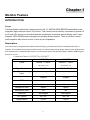
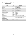
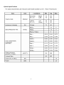
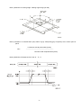
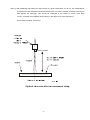
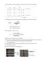
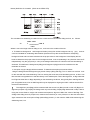
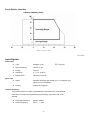
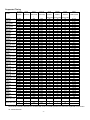
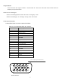
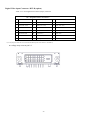
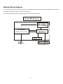
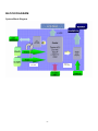
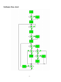
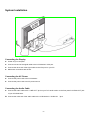
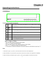
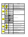
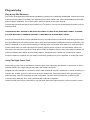
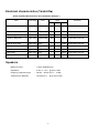
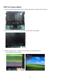
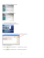
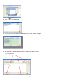
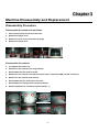
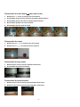
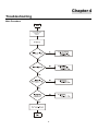
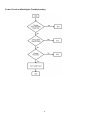
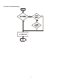
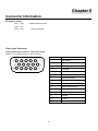
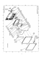
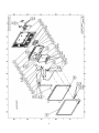
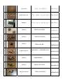
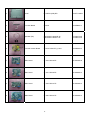
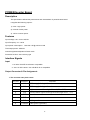
Acer V173 Service Guide Service guide files and updates are available on the CSD web: for more information, Please refer to http://csd.acer.com.tw/ -1- Copyright Copyright © 2008 by Acer Incorporated. All rights reserved. No part of this publication may be reproduced, transmitted, transcribed, stored in a retrieval system, or translated into any language or computer language, in any form or by any means, electronic, mechanical, magnetic, optical, chemical, manual or otherwise, without the prior written permission of Acer Incorporated. Disclaimer The information in this guide is subject to change without notice. Acer Incorporated makes no representations or warranties, either expresses or implied, with respect to the contents hereof and specifically disclaims any warranties of merchantability or fitness for any particular purpose, Any Acer Incorporated software described in this manual is sold or licensed “as is ”. Should the programs prove defective following their purchase, the buyer (and not Acer Incorporated, its distributor, of its dealer) assumes the entire cost of all necessary servicing, repair, and any incidental or consequential damages resulting from any defect in the software. Acer is a registered trademark of Acer Corporation. Intel is a registered trademark of Intel Corporation. Pentium and Pentium II/III are trademarks of Intel Corporation. Other brand and product names are trademarks and/or registered trademarks of their respective holders. -2- Conventions The following conventions are used in this manual: Screen messages Denotes actual messages that appear on screen Note Gives bits and pieces of additional information related to the current topic. Warning Alerts you to any damage that might result from doing or not doing specific actions. Caution Gives precautionary measures to avoid possible hardware or software problems. Important Reminds you to do specific actions relevant to the accomplishment of procedures. Preface Before using this information and the product it supports, please read the following general information. 1. this Service Guide provides you with all technical information relating to the BASICCONFIGURATION decided for Acer’s “global” product offering. To better fit local market requirements and enhance product competitiveness, your regional office MAY have decided to extend the functionality of a machine (e.g. add-on card, modem, or extra memory capability). These LOCALIZED FEATURES will NOT be covered in this generic service guide. In such cases, please contact your regional offices or the responsible personnel/channel to provide you with further technical details. 2. please not WHEN ORDERING FRU PARTS, that you should check the most up-to-date information available on your regional web or channel. If, for whatever reason, a part number change is made, it will not be noted in the printed Service Guide, for ACER-AUTHORIZED SERVICE PROVIDERS, your Acer office may have a DIFFERENT part number code to those given in the FRU list of this printed Service Guide. You MUST use the list provided by your regional Acer office to order FRU parts for repair and Service of customer machines. -3- WARNING: (FOR FCC CERTIFIED MODELS) NOTE: this equipment has been tested and found to comply with the limits for a Class B digital device, pursuant to Part 15 of the FCC Rules. These limits are designed to provide reasonable protection against harmful interference in a residential installation. This equipment generates, uses and can radiate radio frequency energy, and if not installed and used in accordance with the instructions, may cause harmful interference to radio communications. However, there is no guarantee that interference will not occur in a particular installation. If this equipment does cause harmful interference to radio or television reception, Which can be determined by turning the equipment off and on, the user is encouraged to try to correct the interference by one or more of the following measures: 1. Reorient or relocate the receiving antenna. 2. Increase the separation between the equipment and receiver. 3. Connect the equipment into an outlet on a circuit different from that to which the receiver is connected. 4. Consult the dealer or an experienced radio/TV technician for help. Warning Use only shielded signal cables to connect I/O devices to this equipment. You are cautioned that changes or modifications not expressly approved by the party responsible for compliance could void your authority to operate the equipment. As an ENERGY STAR® Partner our company has determined that this product meets the ENERGY STAR® guidelines for energy efficiency. WARNING: To prevent fire or chock hazard, do not expose the monitor to rain or moisture. Dangerously high voltages are present inside the monitor. Do not open the cabinet. Refer servicing to qualified personnel only. -4- PRECAUTIONS z Do not use the monitor near water, e.g. near a bathtub, washbowl, kitchen sink, laundry tub, Swimming pool or in a wet basement. z Do not place the monitor on an unstable trolley, stand, or table. If the monitor falls, it can injure a person and cause serious damage to the appliance. Use only a trolley or stand recommended by the manufacture or sold with the monitor. If you mount the monitor on a wall or shelf, use a mounting kit approved by the manufacture and follow the kit instructions. z Slots and openings in the back and bottom of the cabinet area provided for ventilation. To ensure reliable operation of the monitor and to protect it from overheating, be sure these openings are not blocked or covered. Do not place the monitor on a bed, sofa, rug or similar surface. Do not place the monitor near or over a radiator or heat register. Do not place the monitor in a bookcase or cabinet unless proper ventilation is provided. z The monitor should be operated only from the type of power source indicated on the label. If you are not sure of the type of power supplied to your home, consult your dealer or local power company. z The monitor is equipped with a three-pronged grounded plug, a plug with a third (grounding) pin. This plug will fit only into a grounded power outlet as a safety feature. If your outlet does not accommodate the three-wire plug, have an electrician install the correct outlet, or use an adapter to ground the appliance safely. Do not defeat the safety purpose of the grounded plug. z Unplug the unit during a lightning storm or when it will not be used for long periods of time. This will protect the monitor from damage due to power surges. z Do not overload power strips and extension cords. Overloading can result in fire or electric shock. z Never push any object into the slot on the monitor cabinet. It could short circuit parts causing a fire or electric shock. Never spill liquids on the monitor. z Do not attempt to service the monitor yourself; opening or removing covers can expose you to dangerous voltages and other hazards. Please refer all servicing to qualified service personnel. z To ensure satisfactory operation, use the monitor only with UL listed computers which have appropriate configured receptacles marked between 100-240V AC, Min. 3.5A. z The wall socket shall be installed near the equipment and shall be easily accessible. -5- SPECIAL NOTES ON LCD MONITORS The following symptoms are normal with LCD monitor and do not indicate a problem. NOTES z Due to the nature of the fluorescent light, the screen may flicker during initial use. Turn off the Power Switch and then turn it on again to make sure the flicker disappears. z You may find slightly uneven brightness in the screen depending on the desktop pattern you use. z The LCD screen has effective pixels of 99.99% or more. It may include blemishes of 0.01% or less such as a missing pixel or a pixel lit all of the time. z Due to the nature of the LCD screen, an afterimage of the previous screen may remain after switching the image, when the same image is displayed for hours. In this case, the screen is recovered slowly by changing the image or turning off the Power Switch for hours. -6- Table of contents Chapter 1 Monitor Feature …………………………………………………………………...………..8 Chapter 2 Operating Instruction ………………………………………………..……………………..27 Chapter 3 Machine Disassembly and Replacement …………………………………..…………42 Chapter 4 Troubleshooting …………………………………………………………………………..56 Chapter 5 Connector Information …………………………………………………………………..59 Chapter 6 FRU List …………………………………………………………………………………… 60 Chapter 7 Schematic Diagram ….……………………………………………………………………..70 -7- Chapter 1 Monitor Feature INTRODUCTION Scope This specification defines the requirements for the 17” MICRO-PROCESSOR based Multi-mode supported high resolution color LCD monitor. This monitor can be directly connected to general 15 pin D-sub VGA connector and eliminates the requirement of optional special display card. It also supports VESA DPMS power management and plug & play function. There is a build-in stereo audio amplifier with volume control to drive a pair of speakers. Description The LCD monitor is designed with the latest LCD technology to provide a performance oriented product with no radiation. This will alleviate the growing health concerns. It is also a space saving design, allowing more desktop space, and comparing to the traditional CRT monitor, it consumes less power and gets less weight in addition MTBF target is 20k hours or more. Comparison Chart of AV578/577 & AV878/877 AV578/577 AV878/877 Normal 17” panel Normal 17” panel M170EG01(VD) M170EG01(VD) Signal Interface D-SUB D-SUB & DVI-D Sync Type for analog input Separate / compatible / Separate / compatible / Color Temp user adjust Support Support DDC DDC2B DDC2B Speaker Option Option Headphone Jack Option Option Microphone Jack No No USB Hub Not support Not support Tilt / Swivel No / No No / No Height Adjust Option Option Panel -8- ELECTRICAL REQUIREMENTS Standard Test Conditions All tests shall be performed under the following conditions, unless otherwise specified. Ambient light : 225 lux Viewing distance : 50 cm in front of LCD panel Warrn up time All specifications : 30 minutes Fully functional : 5 seconds Measuring Equipment : Chroma 2250 signal generator or equivalent, directly Connected to the monitor under test. Minolta CA100 photometer, or equivalent Control settings User brightness control : Maximum (unless otherwise specified ) User contrast control: Typical (unless otherwise specified ) User red/white balance, Green/white balance and Blue/white balance control : In the center (unless otherwise specified ) Power input: 110Vac or 230Vac Ambient temperature: 20 ± 5 ˚C ( 68 ± 9 ˚ F) Analog input mode: 1280 x1024 /60 Hz MEASUREMENT SYSTEMS The units of measure stated in this document are listed below: 1 gamma = 1 nano tesla 1 tesla = 10,000 gauss cm = in x 2.54 lb = kg x 2.2 degrees F = [°C x 1.8] + 32 degrees C = [°F - 32]/1.8 u' = 4x/(-2x + 12y + 3) v' = 9y/(-2x + 12y + 3) x = (27u'/4)/[(9u'/2) - 12v' + 9] y = (3v')/[(9u'/2) - 12v' + 9] nits = cd/(m2) = Ft-L x 3.426 lux = foot-candle x 10.76 -9- LCD monitor General specification (AUO M170EG01(VD)) General specification - 10 - Optical specifications - 11 - Note 1) Definition of Viewing Angle: Viewing angle range (10≤CR) Note 2) Definition of Contrast Ratio (CR): Ratio of gray max(Gmax),gray min(Gmin) at the center point of panel. Luminance with all pixels white (Gmax) CR= ⎯⎯⎯⎯⎯⎯⎯⎯⎯⎯⎯⎯⎯⎯⎯⎯⎯⎯⎯⎯ Luminance with all pixels black (Gmin) Note 3) Definition of Response time: Sum of TR , TF - 12 - Note 4) After stabilizing and leaving the panel alone at a given temperature for 30 min, the measurement should be executed .Measurement should be executed n a stable, windless ,and dark room.30 min after lighting the back-light. This should be measured in the center of screen. Dual lamp current :13.0mA(6.5mA x2)(Refer to the note(1) in the page 14 for more information ). Environment condition :Ta=25±2°C Optical characteristics measurement setup - 13 - Notes 5) Definition of Luminance of White : measure the luminance of white at center point. Notes 6)Definition of 5 points brightness uniformity (Measuring points: Refer to the Note 5) Bmax BUNI= ⎯⎯⎯⎯⎯⎯⎯ Bmin Bmax: Maximum brightness Bmin: Minimum brightness Notes 7) Definition of Flicker level Flicker Voltage pp F = ⎯⎯⎯⎯⎯⎯⎯⎯⎯ x 100 % LMD Voltage dc ♦ One maximum value of three estimated values. ♦ For this test ,an LMD(Light Measurement Device)is needed with adequate response time to track any visible rate flicker component and with a voltage level output proportional To luminance intensity. ♦ Test Pattern: For dot inversion Driving(Gray levels of foreground dots on the test panel Are G22,G32,and G45) ♦ Test Point :Center point of the display area - 14 - Note 8) Definition of Crosstalk (Refer to the VESA STD) The calculation for shadowing is made from the 2 luminance measurements Gbkg and Lsh, as follows: Lmax -Lmin CT = ⎯⎯⎯⎯⎯⎯ x100 % Lmin Where Lmax is the larger value of Gbkg or Lsh , and Lmin is the smaller of the two. ♦ To determine background and foreground levels (colors),first set the background to any gray scale or color level suitable for shadowing determination.(Note that it may take several iterations of adjusting background level and box levels to determine the proper value for the background .Next display the box levels to determine the proper value for the background level. Look for shadowing in any direction from box E. Independently vary the gray level (or color) of the background and box E until the worst case shadowing is observed. This defines the background (Gbkg) and foreground (Gfg) levels to be maintained for the remainder of the test. ♦ One point only (the target) will be measured. To determine that point proceed as follows Using the background and foreground gray levels of step1 (Gbkg and Gfg). Turn on each box at a time. Look for the case with the worst shadowing. The box causing the worst case is the shadowing source, or Bsrc. Use Bsrc and the box opposite from it that lies directly in the shadow path. That is the target box, or Btgt. Note that box Eight be either Bsrc or Btgt, depending on the shadowing conditions, but typically Bsrc and Btgt will be a pair of opposite boxes, A&C or B&D. Btgt will only be displayed for aligning the LMD. It will be turned off for the actual measurement. ♦ The target box point (Btgt) will be measured with the source box (Bsrc) turned on then off. (Btgt is for alignment purpose only) Display the background only at level Gbkg. Display Btgt determined in step 2 above. Using the correct distance, angle, and measurement aperture, align the LMD to the center of the Btgt. Turn off Btgt. With Gbkg set to its proper level, measure the luminance (or color). Next,turn on the source box Bsrc. Again measure at the center point of Btgt (without Btgt present.). In this case the LMD will be measuring the shadowing level, Lsh. - 15 - Panel Relative Humidity JP777-E02 Input Signals Video input • • • • • DVI (option) Type Analog R, G, B. Input Impedance 75 ohm +/- 2% Polarity Positive Amplitude 0 - 0.7 +/- 0.05 Vp Display Color same as LCD panel • Signal separate horizontal and vertical sync, or composite sync which are TTL compatible • Polarity positive and negative. Sync input Interface frequency The following frequency range is generalized by supported timing. If the entered mode does not match the supported timing the display optimization will not be assured. • • Horizontal Frequency 30KHz --80KHz Vertical Frequency 49Hz -------75Hz - 16 - Supported Timing FH(KHZ) SYNC TOTAL ACTIVE SYNC FRONT BACK PIXEL WIDTH PORCH PORCH FOREQ.(MHZ ) TIMING FV(HZ) 640x350 VGA-350 640x400 NEC PC9801 640x400 VGA-GRAPH 640x400 NEC PC9821 640X480 VESA-PAL 640x480 VGA-480 640x480 APPLE MAC-480 640x480 VESA-480-72Hz 640x480 VESA-480-75Hz 720x400 VGA-400-TEXT 832x624 APPLE MAC-800 800x600 SVGA 800x600 VESA-600-60Hz 800x600 VESA-600-72Hz 800x600 VESA-600-75Hz 1024x768 XGA 1024x768 COMPAQ-XGA 1024x768 VESA-768-70Hz 1024x768 VESA-768-75Hz 1024x768 APPLE MAC-768 1152x864 (60Hz) 1152x864 (70Hz) 1152x864 (75Hz) 1280x960 (60Hz) 1280x960 (70Hz) 1280x960 (75Hz) 1280x1024 VESA-1024-60H z 1280x1024 VESA-1024-75H z POLARITY (DOT/LINE (DOT/LINE) ) 31.469 70.087 24.83 56.42 31.469 70.087 31.5 70.15 31.469 50.030 31.469 59.94 35.00 66.67 37.861 72.809 37.5 75 31.469 70.087 49.725 74.55 35.156 56.25 37.879 60.317 48.077 72.188 46.875 75 48.363 60.004 53.964 66.132 56.476 70.069 60.023 75.029 60.24 75.02 54.054 59.270 63.851 70.012 67.50 75.00 60.00 60.00 70.00 70.00 75.00 75.00 64 60 + – – – – + – – – – – – – – – – – + – – + + + + + + + + – – + + – – + + – – + + + + + + + + + + + + + + 800 449 848 440 800 449 800 449 800 629 800 525 864 525 832 520 840 500 900 449 1152 667 1024 625 1056 628 1040 666 1056 625 1344 806 1328 816 1328 806 1312 800 1328 803 1480 912 1480 912 1600 900 1800 1000 1800 1000 1800 1000 1688 1066 640 350 640 400 640 400 640 400 640 480 640 480 640 480 640 480 640 480 720 400 832 624 800 600 800 600 800 600 800 600 1024 768 1024 768 1024 768 1024 768 1024 768 1152 864 1152 864 1152 864 1280 960 1280 960 1280 960 1280 1024 80 75 + + 1688 1066 1280 1024 (DOT/LINE) (DOT/LINE) (DOT/LINE) 96 16 48 2 37 60 64 64 80 8 7 25 96 16 48 2 12 35 64 16 80 2 13 34 96 16 48 2 62 85 96 16 48 2 10 33 64 64 96 3 3 39 40 16 120 3 1 20 64 16 120 3 1 16 108 18 54 2 12 35 64 32 224 3 1 39 72 24 128 2 1 22 128 40 88 4 1 23 120 56 64 6 37 23 80 16 160 3 1 21 136 24 160 6 3 29 176 16 112 4 8 36 136 24 144 6 3 29 96 16 176 3 1 28 96 32 176 3 3 29 96 40 192 3 13 32 96 32 200 3 1 44 128 64 256 2 2 32 112 96 312 3 1 36 112 96 312 3 1 36 112 96 312 3 1 36 112 48 248 3 1 38 144 3 16 1 248 38 25.175 21.05 25.175 25.197 25.175 25.175 30.24 31.5 31.5 28.322 57.2832 36 40 50 49.5 65 71.664 75 78.75 80 80 94.499 108.00 108.00 126.00 135.00 108 135 Note: Mode 640x350, 640x400 and 720x400 will locate on middle position but cannot be expanded to full screen on vertical direction - 17 - Support Modes There will be 28 total support modes to accommodate the above mode and other video modes within the frequency range of the monitor. 85Hz refresh rate Support Monitor should display 85Hz refresh rate mode as emergency mode. Monitor should display “Out of Range” warning menu at this mode. Video input Connector Analog Video input Connector: 15pins mini D-Sub Table 2.4.5. Pin assignment for D-sub connector PIN NO. Separate Sync 1 RED VIDEO 2 GREEN VIDEO 3 BLUE VIDEO 4 GROUND 5 GROUND 6 RED GROUND 7 GREEN GROUND 8 BLUE GROUND 9 PC5V (+5V DDC) 10 CABLE DETECTION 11 GROUND 12 SDA 13 H.SYNC 14 V.SYNC 15 SCL Color of plastic parts: Blue (PC99) 5 1 10 15 6 11 D-sub connector - 18 - Digital Video input Connector: DVI-D (option) Table 4-3-3. Pin assignment for DVI-D (24pin) connector Pin – Assignment of DVI –D connector : 1 TX2- 9 TX1- 17 TX0- 2 TX2+ 10 TX1+ 18 TX0+ 3 Shield (TX2 / TX4) 11 Shield (TX1 / TX3) 19 Shield (TX0 / TX5) 4 NC 12 NC 20 NC 5 NC 13 NC 21 NC 6 DDC-Serial Clock 14 +5V power *) 22 Shield (TXC) 7 DDC-Serial Data 15 Ground (+5V) 23 TXC+ 8 No Connect 16 Hot plug detect 24 TXC- *) In case, the power of the PC unit is switched off and the power of the monitor is switched on, no voltage may occur at pin 14. - 19 - Monitor Block Diagram The LCD monitor will contain an main board, an inverter/ power board, key board and internal adapter which house the flat panel control logic, brightness control logic and DDC. The inverter board will drive the backlight of panel and the DC-DC conversion. Power board (include: AC/DC,inverter) - 20 - BLOCK DIAGRAM System Block Diagram 24LC16 (24LC02B) 24LC02B - 21 - Monitor board layout LABEL Component LABEL Component U1 24LVC2B CN1 D-SVB 15 PIN U3 TSU16AJ CN6 E&T 4501-19 U6 24LC16B(24LVO2B) CN3 E&T 4501-09 U5 MX810 J502 E&T 4501-05 U7 APM4461 J501 E&T 4501-03 U4 PMX10E8D50I CN5 P-TWO AFN300 30P U8 APL1085-3.3 CE U9 APL1117-2.5 VC U501 ATPA6019 - 22 - Software flow chart - 23 - Software Flow Chart 1. MCU initialize 2. Is the eeprom blank? 3. Program the eeprom by default values. 4. Get the PWM value of brightness from eeprom. 5. Is the power key pressed? 6. Clear all global flags. 7. Are the “<” and “>” (Adjust key) and power key. 8. Enter factory mode 9. Save the power key status into eeprom. Turn on the LED and set it to green color. Scalar initialize. 10. In standby mode? 11. Update the lift time of back light. 12. Check the analog port, are there any signals coming? 13. Does the scalar send out a interrupt request? 14. Wake up the scalar 15. Are there any signal coming from analog port? 16. Display “Cable Not Connected” message, and go into standby mode after the message disappear. 17. Program the scalar to be able to show the coming mode. 18. Process the OSD display. 19. Read the key board. Is the power key pressed? - 24 - General Instructions Press the power button to turn the monitor on or off. The other control buttons are located at front panel of the monitor. By changing these settings, the picture can be adjusted to your personal preferences. z The power cord should be connected. z Connect the video cable from the monitor to the video card. z Press the power button to turn on the monitor position. The power indicator will light up. External Controls 1 2 LED / Power Key 3 >/ Volume 4 </ Volume - 25 - 5 MENU/ENTER 6 Auto Adjust Key/Exit 7 eCOLOR System Installation Connecting the Display z Power off your computer. z Connect one end of the signal cable to the LCD Monitor’s VGA port. z Connect the other end of the signal cable to the VGA port on your PC. z Make sure connections are secure. Connecting the AC Power z Connect the power cord to the LCD Monitor. z Connect the power cord to an AC power source. Connecting the Audio Cable z Connect the audio cable to the " LINE OUT " jack on your PC's audio card or to the front panel's “AUDIO OUT” jack of your CD ROM drive. z Connect the other end of the audio cable to the LCD Monitor's " AUDIO IN " jack. - 26 - Chapter 2 Operating Instructions CONTROLS Control panel (monitor front panel) 1 Power LED, will be blue when monitor is on; be amber when in power saving mode. 2 Power ON/OFF switch, push to ON and push to OFF. (toggle switch) 3 Function change or Adjust increase. 4 Function change or Adjust decrease. 5 Menu Function select 6 Auto Auto adjust or Exit OSD menu. 7 e eColor management function Note: 1. Press button 4 (plus +) or (minus -) at the same time can activate “Volume Adjustment”. 2. When OSD Menu is off, press button 5 (auto) at the same time can activate “Auto Adjustment” immediately. 3. When into Factory mode press 4 (plus +),(minus -) and 1 (power) together 2 seconds at same time. - 27 - Main OSD Menu: Outline: z P/X Series OSD behave When user press “MENU” button on front bezel A. Acer eColor Management If selected to “Acer eColor Management” item, will appear the Acer eColor” OSD B. USER If selected to “USER” item, will appear the Standard OSD I. Only Analog Input Model II. Only Dual Input ModeI - 28 - The description for control function : A. Acer eColor Management Main Menu Sub Menu icon icon Sub Menu item Description N/A User mode User defined. Settings can be fine-tuned to suit any situation N/A Text mode Optimal balance of brightness and contrast prevent eyestrain. The most comfortable way to read onscreen text N/A Standard mode Default Setting. Reflects native display capability N/A Graphic mode Enhances colors and emphasize fine detail N/A Movie mode Displays scenes in clearest detail. Pictures and photographs appear in vibrant colors with sharp detail B. USER Main Menu Sub Menu icon icon Sub Menu item Contrast Brightness ACM Focus Clock Description Adjust the contrast between the foreground and background of the screen image Adjust the background brightness of the screen image ACM (Adaptive Contrast Management)A CM ON/OFF Switch, default "OFF" Adjust picture Focus (available in analog mode only) Adjust picture Clock (available in analog mode only) - 29 - Main Menu icon Sub Menu icon Sub Menu item H. Position V. Position Description Adjust the horizontal position. (available in Analog mode only) Adjust the vertical position. (available in Analog mode only) N/A Warm Set the color temperature to warm white. N/A Cool Set the color temperature to cool white. User /Red User /Green Adjusts Red/Green/Blue intensity User /Blue N/A English 繁體中文 N/A Deutsch N/A Français N/A Español N/A N/A Italiano 简体中文 N/A 日本語 N/A N/A Suomi Hollands N/A Русский N/A N/A N/A N/A Multi-language selection. EMEA version OSD only H. Position Adjust the horizontal position of the OSD. V. Position Adjust the vertical position of the OSD. OSD Timeout Adjust the OSD timeout. Analog Select input signal from analog (D-Sub) Digital (only Dual Select input signal from digital(DVI) Input Model) (only Dual-Input Model) DDC/CI Turn ON/OFF DDC/CI support - 30 - N/A Information N/A Reset N/A Exit Show the resolution, H/V frequency and input port of current input timing. Clear each old status of Autoconfiguration and set the color temperature to Cool. Save user adjustment and OSD disappear. - 31 - Hot-Key Menu: eColor Management: Outline: User d Text mode Standard Graphic d d Movie d Operation instructions Acer eColor Management Step 1: Press “ Key” to open the Acer eColor Management OSD and access the scenario modes Step 2: Press “<” or “>” to select the mode Step 3: Press “Auto Key” to confirm the mode and run Auto Adjust Features and Benefits Mode Standard Text Graphics Features Benefits Default settings Reflects native display capability Optimal balance of brightness and The most comfortable way to read onscreen contrast prevents eyestrain text Enhances colors and emphasizes fine Pictures and photographs appear in vibrant detail colors with sharp detail Movie Displays scenes in clearest detail U ser User defined Presents great visuals, even in unsuitably-lit environments Settings can be fine-tuned to suit any situation - 32 - Audio Volume control:(option) Outline: The description for Hot-Key function : Item Volume Operation Icon Description When the OSD is closed, press Volume of Audio adjustment. The Left or Right button will be Volume Audio will be Mute when volume=0. Adjustment Reset Range Value 0-100 50 Hot-Key Function OSD Message: Outline: The description for OSD Message : Item Description Auto Config When User Press Hot-Key “Auto”, will show this message, and the monitor do the auto config Please Wait function. Input Not When the Hsync Frequency, Vsync Frequency or Resolution is out of the monitor support range, Supported will show this message. This message will be flying. Cable Not When the video cable is not connected, will show this message. This message will be flying. Connected No Signal When the video cable is connected, but the is no active signal input, will show this message, then enter power saving. - 33 - LOGO: When the monitor is power on, the LOGO will be showed in the center. Item of Factory menu Vendor may customize design and add adjustment items Factory menu as far as all required items are included. 1) Bright Adjust Brightness and Contrast value to Max. 2) Auto Balance Adjust each R, G, B contrast (gain) and offset. Method of auto adjust is depends on hardware. Adjusted value of R, G, B gain shall be used for initial value of Contrast in user menu. All value shall be adjustable manually. This function shall be located in 3. tag of Factory menu. 3) Factory color temp data edit Following data for color temp shall be editable manually. -color temp default preset No. - 34 - Plug and play Plug & play DDC2B feature This monitor is equipped with VESA DDC2B capabilities according to the VESA DDC STANDARD. It allows the monitor to inform the host system of its identity and, depending on the level of DDC used, communicate additional information about its display capabilities. The communication channel is defined in two levels, DDC2B. The DDC2Bis a bidirectional data channel based on the I2C protocol. The host can request EDID information over the DDC2B channel. THIS MONITOR WILL APPEAR TO BE NON-FUNCTIONAL IF THERE IS NO VIDEO INPUT SIGNAL. IN ORDER FOR THIS MONITOR TO OPERATE PROPERLY, THERE MUST BE A VIDEO INPUT SIGNAL. This monitor meets the Green monitor standards as set by the Video Electronics Standards Association(VESA) and/or the United States Environmental Protection Agency (EPA) and The Swedish Confederation Employees (NUTEK). This feature is designed to conserve electrical energy by reducing power consumption when there is no video-input signal present. When there is no video input signal this monitor, following a time-out period, will automatically switch to an OFF mode. This reduces the monitor’s internal power supply consumption. After the video input signal is restored, full power is restored and the display is automatically redrawn. The appearance is similar to a “Screen Saver” feature except the display is completely off. The display is restored by pressing a key on the keyboard, or clicking the mouse. Using The Right Power Cord The accessory power cord for the Northern American region is the wallet plug with NEMA 5-15 style and is UL listed and CSA labeled. The voltage rating for the power cord shall be 125 volt AC. Supplied with units intended for connection to power outlet of personal computer: Please use a cord set consisting of a minimum No. 18 AWG, type SJT or SVT three conductors flexible cord. One end terminates with a grounding type attachment plug, rated 10A, 250V,CEE-22 male configuration. The other end terminates with a molded-on type connector body, rated 10A, 250V, having standard CEE-22 female configuration. Please note that power supply card needs to use VDE 0602, 0625, 0821 approval power cord in European counties. - 35 - White Color Temperature White color temperature is 4 preset as 9300, 7500,6500 and User, Default value of user color should be user which is maximum setting for panel. Target of color setting Color Color Coordinate Tolerance Color Coordinate Tolerance Temp. x y 9300K 0.283 0.297 6500K 0.313 0.329 User - - u’ v’ +0.03 0.189 0.446 u’v’ < 0.01* +0.03 0.198 0.469 u’v’ < 0.01* - - - *) TCO’0X A.2.6.1 requirement User should follow “Microsoft Windows Color Quality Specification for Liquid Crystal Display OEM’s”. (http://www.microsoft.com/hwdev/tech/color/ColorTest.asp) Power Management 1. Meet VESA DPMS proposal 2. Power Consumption Meet VESA DPMS Proposal On mode DPMS DC power off 40Wmax 2Wmax 1Wmax disconnection 2Wmax Blue Amber Dark 1. Amber (stand-by; suspend; off mode) 2. Dark (DC power off) Measured from AC input end of AC power and don’t include audio at power-saving state The stand-by, suspend and off mode recover to on mode about 3 seconds. Plug & Play (EDID) The monitor will be capable of sending a VESA standardized EDID file through the DDC (pins 12, 15 of the VGA connector). Audio Technical specification General Description: Output power : 1W + 1W maximum Total harmonic distortion : Less than 1 % (except speakers distortion) Input signal sensitivity : 0.5 Vrms for full output Input impedance : Frequency response range : 20Hz – 20kHz (except speakers response) 47 Kohm +/- 5 % - 36 - Electrical characteristics (Tamb=25°) Audio amplifier(USE Panasonic VP-7723A Audio Analyzor. ) Item Audio Input Freq. Comment Spec. Input Voltage(V) Min. Typ. Max. - 0.5Vm - s Input Current(m A) - 500 800 - - 6dB Audio Voltage Gain 500m Vrms 1KHz Frequency Response 500m Vrms 300Hz-20KH -10dB Volume Max.,load 4 Ω - +10d B Volume Max.,load 4 Ω - -40dB Volume Max.,load 4 Ω z Signal to Noise ratio 500m Vrms 1KHz - Total harmonic distortion 500m Vrms 1KHz Cross talk 500m Vrms 1KHz - - -30dB Volume Max.,load 4 Ω Output Watt. 500m Vrms 1KHz - - 0.5W - - - 1% Volume Control Speakers Maximum power : 1 W per speaker(max) Impedance : 6 ohm +/- 15 % @ 1kHz 1.0Hz Frequency response range : 300 Hz – 20 kHz (S.P.L. – 10 dB) Total harmonic distortion : Less than 5 % - 37 - @ 0.125 W 1kHz except speakers distortion Volume Max.,load 4 Ω Analog SOP for Factory Mode 1. Connect D-SUB cable and Power cord according to the graphic, and input power and signal 2. Turn on the monitor by clicking the power key, and show the normal image 4. Press the “Function -”key, “Function +” key & “Power” key simultaneously and Factory Model is got into as below - 38 - SOP for ISP (Firmware upgrade) 1. Operation system & Connection a. PC (Win XP), b. ISP tool, c. VGA cable, d. RS232 cable b. Turn on the power of monitor. VGA cable shall be connected to ISP out port. 2. Install ISP BD driver on PC system a. Click the ISP driver program(port95nt.exe) b. Click to next page . - 39 - c. Click d.Click or to next page to complete this setup. 3. Open the ISP program on PC system Click the ISP program (RTD2120_ISP_vXX.exe) 4. Load F/W files (There are two F/W files, XXX_code.hex&xxx_data.hex) a. Hold on the K/B“Ctrl”Key, b. Click to load F/W file( Ex:C:\Code\Acer \Acer_code.hex; c. Click to load F/W file (Ex:C:\Code\Acert\Acer_data.hex; - 40 - d. Click to update F/W. e. The ISP process would be finished after the menu occur the “PASS” message. 5. We shall hold on the K/B "Ctrl" key before we want to use below functions. (1). Load F/W files。 (2). Config Function (3). Verify CheckSum function - 41 - Chapter 3 Machine Disassembly and Replacement Disassembly Procedure Disassemble the stand neck and base 1. Push release button and remove the base. 2. Remove the hinge cover. 3. Remove the four screws to release the hinge. 4. Remove the stand neck Disassemble the chassis 1. To separate the back cover. 2. Remove the two screws from hinge bracket. 3. Disassemble the FFC form VL board 4. Remove the two screws from VGA connector (four screws from VGA and DVI connector). 5. Remove the two screws form chassis. 6. Disassemble the FFC form panel connector. 7. Disassemble four voltage lines from power board. 8. Remove speaker four screws form panel bracket R/L - 42 - Disassemble the main board and the power board 1. Remove the five screws to release line from Chassis 2. Disassemble audio line from VL board and power board (option). 3. Disassemble power line from VL board and power board. 4. Disassemble speaker line from VL board. 5. Disassemble the FFC form VL board Disassemble the mylar 1. Remove the two mylars to release line from Chassis 2. Remove the one mylar to release line from Chassis Disassemble the key board 1. Remove three screw to release VK board from bezel. 2. Disassemble the button from bezel. Disassemble the panel bracket 1. Remove tow screws to release panel bracket R from penal. 2. Remove tow screws to release panel bracket L from penal . - 43 - Chapter 4 Troubleshooting Main Procedure Connect all of the Devices to AA677 44 Power Circuit and Backlights Troubleshooting 45 Performance Troubleshooting 46 Function Troubleshooting 47 Chapter 5 Connector Information Phonejack stereo PIN1. right : CEE22 typed connector PIN2. Left PIN3. Gnd : Line-in receptacle Video input Connector Analog Video input Connector: 15pins mini D-Sub Table 2.4.5. Pin assignment for D-sub connector PIN NO. 5 1 10 15 6 11 48 Separate Sync 1 RED VIDEO 2 GREEN VIDEO 3 BLUE VIDEO 4 GROUND 5 GROUND 6 RED GROUND 7 GREEN GROUND 8 BLUE GROUND 9 PC5V (+5V DDC) 10 CABLE DETECTION 11 GROUND 12 SDA 13 H.SYNC 14 V.SYNC 15 SCL Chapter 6 FRU (Field Replaceable Unit) list This chapter gives you the FRU (Field Replaceable Unit) listing in global configurations of AL1712. Refer to this chapter whenever ordering for parts to repair or for RMA (Return Merchandise Authorization). NOTE : Please note WHEN ORDERING FRU PARTS, that you should check the most up-to-date information available on your regional web or channel(http://aicsl.acer.com.tw/spl/). For whatever reasons a part number change is made, it will not be noted in the printed Service Guide. For ACER-AUTHORIZED CERVICE PROVIDERS, your Acer office may have a DIFFERENT part number code to those given in the FRU list of this printed Service Guide. You MUST use the local FRU list provided by your regional Acer office to order FRU parts repair and service of customer machines. NOTE: To scrap or to return the defective parts, you should follow the local government ordinance or regulations on how best to dispose it, or follow the rules set by your regional Acer office on how to return it. 49 50 51 Part list No. Photo Part Name Description Part No. 1 BEZEL ASSY(V173) AV5701 ABS 94HB MBK94 GP APAV570110I 2 Base Assy AV5713 ABS 94HB MBK94 GP APAV571310I 3 BACK COVER ASSY(Analog) BACK COVER ASSY(Dual) AV5203 ABS 94HB MBK94 GP APAV570300I APAV570310I APAV570320I APAV570330I 4 BUTTON AV5731 MBK94 ABS 94HB GP FBAV573100I 5 STAND NECK ASSY(AV698) AV5715 ABS 94HB MBK94 GP APAV571520I 6 CHASSIS(Analog) CHASSIS(Dual) VP949+VL949 D-SUB GP ECAV571200I ECAV571210I ECAV571220I ECAV571230I 7 MYLAR(UPPER) MYLAR(LOWER) AV5743 FR700 T=0.43MM 94V0 GP AV5744 FR700 R=0.43MM 94V0 GP ELAV694300I ELAV694400I 8 SOCKET MYLAR AV5742 FR700 T=0.43MM 94V0 GP ELAV574200I 9 PANEL BRACKET_L AV5721 SECC T=0.8MM GP ECAV572100I 10 PANEL BRACKET_R AV5722 SECC T=0.8MM GP ECAV572200I 11 HINGE BREAKET AV5732 SECC T=0.8MM GP ECAV573200I 12 HINGE COVER(L/R) AV5747 MBK94 ABS 94HB GP FAAV574700I 52 AV5741 PC CLEAR GP 13 LED LENS 14 NECK EMI PLATE 15 RUBBER 16 SCREW 17 SCREW M3X0.5+4I-NI(NL) 18 SCREW TPB-2-2.8I (ZK) 19 SCREW SPECIAL 20 SCREW MAB0000540I 21 SCREW M4X0.7+8F-NI GP 22 TAPPING SCREW AV574C FCAV574100I SUS301 1/2H T=0.15mm GP EEAV574C00I AV5749 Silicon 20X10X2T mm GP M3X0.5+4I-NI(GP) FHAV574900I FCAV574100I MAA0000320I MAB0000340I 4#-40UNCX12.7 WASHER D=5.0 GP MAAA001933I TPB-4+12I-ZK(GP) 53 MAB0000540I MAA1000110I MAB0000120I 23 panel M170EG01(VD)-RR AC6VT1703R2 24 Function Board VK-948 454AEN30L11 25 Speaker (R/L) 2W 6OHM C4020A R-2P 2W 6OHM C4020A L-3P CG10021V22I CG10021V23I 26 Power& Inverter Board VP-949 LAV877TA_7.5mA 453ADS30L51 27 Main board VL-949 LAV578TA 461AG430L22 28 Main board VL-951 LAV878TA 461AG630L21 29 Main board VL-948 LAV577TA 461AG330L21 30 Main board VL-950 LAV877TA 461AG530L21 54 31 Main board to LCD Cable 30P G P1PAD0.65 30CM 55 NBX3010710I POWER/Inverter Board Description This specification defined the performance and characteristic of power/inverter board. It supplies the following outputs : 1). 5Vdc: Logic power. 2). 5Vaudio: Audio power. 3). 19Vinv: Inverter power. Features Input Voltage: 100 ~ 240 ±10%Vac Input Frequency: 47 ~ 63Hz Input power consumption: Less than 1W @ minimum load Total output power: 40Wmax Inverter brightness adjustment: Burst mode Protection function: auto-recovery type Interface Signals Input 1. AC Inlet: HUAJIE SA-4S-328 or compatible. 2. J701: SC SCJ-0345-1-X-9 3.6D BLU 3P or compatible. Output Connector & Pin Assignment: 1. The connecter was pitch 2.0mm PIN NO. Function 1 +5Vdc +5Vdc supply for logical board 2 +5Vdc +5Vdc supply for logical board 3 Vbri Brightness control from logical board (0V to 3.3V) 4 Ven Inverter enable signal from logical board (high active , >3V) 5 GND Ground 6 GND Ground 7 GND Audio ground 8 Function +5Vaudio Audio power (optional). 56 2.Inverter-side connecter : ACES 88451-020N-01 2P3.5 LOCK or equivalent. PIN NO. Function Comment 1 Cth VBLH(High voltage) 2 Ctl VBLL(Low voltage) Electrical Specification: AC-DC Electrical specification Input Specification No Item Condition Min. Typ. Max. Unit 1 Input Voltage ----- 100 --- 240 Vac 2 Input Frequency ----- 47 --- 63 Hz 3 Input Current ----- --- --- 0.8 Arms 4 Inrush Current --- 30 A0-P --- 50 A0-P Cold Start @Vin=100Vrms --- Cold Start @Vin=240Vrms 5 Hold Up Time @full load & 100Vac input 10 --- --- ms 6 Turn on time Vin =110Vac --- 1.0 --- S 7 Efficiency Full load --- 70 --- % 8 Consumption Vin=240Vac,@ no load --- --- 1 W AC-DC Output Specification Tolerance Output Current Voltage Tolerance Output Voltage --- MIN MAX +5Vdc +5 /-3 % 0.05A 1.5A 4.85~5.25V dc +19Vinv +35/-5 % 0A 2A 24~18Vdc +5Vaudio ±5% 0A 0.6A 4.75~5.25Vdc Ripple 1. Measured at DC output terminals which are paralleled with a 10uf Ecap &0.1uf Ceramic cap. 2.Band width is limited within --- 1% Noise +19Vinv:190mVp-p --- 20MHz. Dynamic Load Regulation +5Vdc:50mVp-p 3% +5Vdc:150mVp-p +19Vinv:570mVp-p 50~100% or 100~50% load change of any DC output @50% duty of --- ±5% --- --- ±10% --- 1MHz (min.) Over / Under Sh @ Power line on/off *+5Vdc load regulation test: the +19Vinv loading at 2.0A 57 *+19Vinv load regulation test: the +5Vdc loading at 1.5A Protection function 1) SCP: Short circuit protection must be acted on both outputs 2) OPP: Should be protected when output power consumption is within ~ 55W Inverter Electrical Specification: For 17” Panel Condition Min. Typ. Max. Unit Input Voltage --- --- 19 --- V Input Current --- --- 1.5 --- A Backlight ON/OFF Control Brightness Adjust ON 3.3 V OFF 0 V Min. Luminance / Max. --- 30% --- --- --- Vrms Luminance Output Voltage Vin=19V, Iout=7mA --- 650 Brightness lamp current in 7mA 250 300 Vbri=0.45V~3.6V 3 7.5 8 mA Frequency --- 40 --- 70 KHz Lamp start voltage @0℃ 1650 --- --- Vrms Striking Time --- 1 --- S Lamp Current Balance --- --- ±0.3 --- mA Efficiency Vin=19V --- 80 --- % Output Current(Each Cd/m² connector) 58 SAFETY Leakage Current: 0.25mA @ 100Vac 3.5mA @ 264Vac Insulation Resistance: more than 3M ohms while withstanding a voltage of 500Vac Hi-Pot: 3Kvac with using 3mA cut off current 59 Power Consumption The monitor is equipped with a power-management according to the below. There is a delay of 5s … 7s before the transition from On-state to any power saving state to avoid unintentionally entering of a power saving stage during display resolution and timing mode changes. Transition from any power saving state to another can be instantaneous. The recovery from Off-state requires no manual power on. Mode H-Sync. V-Sync. Video Pw-cons. Indicator Rec. time* Power-On on on active < 40W Blue LED -- DPMS off off off blanked < 2W Orange LED < 5S < 1W Dark LED DC Switch-off SYNC. On means: Normal operation SYNC. Off means: H sync. F < 10KHz duty cycle > 25% V sync. F < 10Hz duty cycle > 25% CONNECTORS / CONTROLS Connectors Power Analog RGB - : Monitor rear side : AC Inlet : Monitor rear side / Data Cable : 15-pin D-sub female / male Pin – Assignment of 15-pin D-sub: - 1 Red Video 9 +5V FOR DDC 2 Green Video 10 Detect 3 Blue Video 11 Serial Data for ISP 4 Serial Clock for ISP 12 Serial Data for DDC 5 Ground 13 H-Sync. 6 Red Ground 14 V-Sync. 7 Green Ground 15 Serial Clock for DDC 8 Blue Ground Audio : Monitor rear side : -PC I/P for PC : 3.5mm Stereo female Monitor Control Keys KEY : Power , Menu , Adjust +/- , Vol +/-, Auto Position Of Controls Position of all switches : Bottom side of front bezel Position of LED : Bottom side of front bezel 60 Chapter 7 Schematic Diagram 61 62 63 64 65 66 67 68 69 70 71 72 73 74 75 76 77 78 79 80 81 82