1
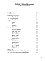
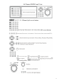
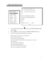
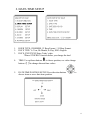
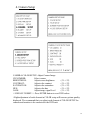
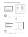
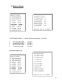
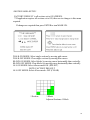
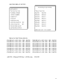
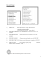
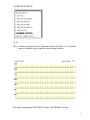
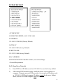
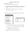
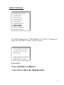
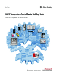
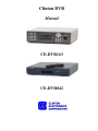
Clinton DVR
Manual
CE-DVR163
CE-DVR042
SAFETY PRECAUTIONS
ABOUT THIS MANUAL
2
BEFORE READING THIS MANUAL
3
Digital Video Recorder
Table of Contents
Safety Precautions
Table of Contents
16 CH DVR Front Panel
Back Panel
4 CH DVR Front Panel
Back Panel
Installation
Log-In
Picture
Playback
Time-Search
Basic Operation
HDD Information
Date-Time Setup
Display Setup
Camera Setup
Buzzer Setup
Audio Setup
System Setup
Advanced Setup
Alarm Setup
Motion Setup
Record Setup
TCP-IP Setup
Password setup
HDD Format
Remote View
16 CH DVR Specifications and Configuration
4 CH DVR Specifications and Configuration
2&3
4
5
6
7
8
9
11
11
13
13
15
16
17
18
19
22
22
24
25
25
27
30
35
36
37
39
44
46
4
16 Channel DVR Front View
16 / 13 / 9 / 4Channel split screen buttons
1/2/3/4/5/6/7/8/9/10/11/12/13/14/15/16 full screen buttons
5
16 Channel DVR Rear View
75 OHM High / Low Adjust
Off: channel Loop-out
On: channel Terminated
RS 232 Connector
Factory use ONLY!
Alarm Connector
Call Monitor: Sequences through all channels used.
To adjust the dwell interval, go to System Setup in main menu.
6
4 Channel DVR Front View
1.
2.
3.
4.
5.
6.
7.
8.
9.
10.
11.
12.
13.
14.
15.
16.
17.
18.
19.
20.
:
4 quad split screen mode button
CHANNEL 1: Channel 1 full screen button
CHANNEL 2: Channel 2 full screen button
CHANNEL 3: Channel 3 full screen button
CHANNEL 4: Channel 4 full screen button
FREEZE:
Picture freeze mode button
ZOOM:
Picture zoom in mode button
AUTO:
Auto sequence mode
PIP:
Picture in picture mode button
REW:
Reverse playback choose button
STEP/DOWN: Playback pause/Direction button down
FF:
Forward playback choose button
STOP/UP:
Press this button to stop playback/Direction button up
MENU BUTTON: Press this button to display the menu setup
LOCK/ESC: Press this button to Lock function
T-SRH:
Press this button to playback time search
DIRECTION/VALUE CHANGE BUTTON: Playback speed choose
(increase)
PLAY BUTTON: Press this button to playback
DIRECTION/VALUE CHANGE BUTTON: Playback speed choose
(reduce)
REC BUTTON: Press this button to start recording image
7
4 Channel DVR Rear View
1.
RS-232 IN: FACTORY USE ONLY!
2.
EXTERNAL HDD: External IDE HDD bay connector
3.
4.
5.
6.
7.
8.
9.
10.
11.
12.
13.
14.
15.
16.
17.
18.
19.
20.
RS-485: RS485 Connector +/COM:
RELAY:
Sensor, relay output
GND
ALARM:
Alarm I/O input
LAN:
Network Connector
CAMERA OUTPUT: CAMERA 1 Video image output
CAMERA INPUT: CAMERA 1 Video image input
CAMERA OUTPUT: CAMERA 2 Video image output
CAMERA INPUT: CAMERA 2 Video image input
CAMERA OUTPUT: CAMERA 3 Video image output
CAMERA INPUT: CAMERA 3 Video image input
CAMERA OUTPUT: CAMERA 4 Video image output
CAMERA INPUT: CAMERA 4 Video image input
MONITOR BNC:
Monitor video BNC Connector
MONITOR S-VIDEO: Monitor S-Video Connector
DC 12V/5A:
Power Input
POWER:
Power Switch ON/OFF
8
The Clinton DVR
The User Manual is created to help you quickly and efficiently install the Clinton
DVR and its most commonly used features. It is important to follow each step in
order and read the instructions carefully to ensure proper programming of the DVR
unit.
It is also important to know the end-user’s requirements in setting up the proper
recording schedules. More detailed information on the other features of the DVR
are located in the DVR Manual, Located on the remote software CD which was
shipped with the DVR.
Installation
9
16 Channel DVR Sensor/Alarm Connections:
,,
13,12,11,10,9,8,7,6,5,4,3 2 1
25,24,23,22,21,20,19,18,17,16,15,14
Pin#
1. ALARM SENSOR 1
2. ALARM SENSOR 2
3. ALARM SENSOR 3
4. ALARM SENSOR 4
5. ALARM SENSOR 5
6. ALARM SENSOR 6
7. ALARM SENSOR 7
8. ALARM SENSOR 8
9. ALARM SENSOR 9
10. ALARMSENSOR 10
11. ALARM SENSOR 11
12. ALARM SENSOR 12
13. ALARM SENSOR 13
Pin#
14. ALARM SENSOR 14
15. ALARM SENSOR 15
16. ALARM SENSOR 16
17. ALARM/MOTION RELAY #2 COM
18. ALARM SENSOR GND
19. ALARM SENSOR GND
20. ALARM SENSOR GND
21. ALARM/MOTION RELAY #1 N.C.
22. ALARM/MOTION RELAY #1 COM
23. ALARM/MOTION RELAY #1 N.O.
24. ALARM/MOTION RELAY #2 N.C.
25. ALARM/MOTION RELAY #2 N.O.
4Channel DVR Sensor/Alarm Connections:
Pin#
Pin#
1. RS 485 2. RS 485 +
3. ALARM/MOTION RELAY COM
4. ALARM/MOTION RELAY N.C.
5. ALARM/MOTION RELAY N.O.
6. ALARM SENSOR GND
7. ALARM SENSOR 1
8. ALARM SENSOR 2
9. ALARM SENSOR 3
10. ALARM SENSOR 4
♦Alarm Input: Short-circuit between any alarm sensor and ALARM SENSOR
GND is recognized as alarm.
10
Logging In
1.
2.
Press the MENU button to enter into the system.
Password enter window pops up:
3.
Password (Account-Admin): 44444
Password (Account-User): 11111
Press Numeric button to choose password and unlock the system.
Notice:
1. ADMIN level can setup all menu functions.
2. USER level cannot setup ADVANCED page.
Picture
Full screen or channel split screen display
Press
button to display 16 / 13 / 9 / 4 channel split screen on the
16channel DVR.
Press
quad button to display 4channel split screen on the 4 channel DVR.
Press numeric buttons to display the desired camera image in full screen.
1.) FREEZE Mode
In live, quad, and full screen mode press
freeze image.
(FREEZE) button to
Press
again to cancel freeze mode.
2.) ZOOM Mode (Display Enlargement)
Go to full screen mode with numeric buttons in live or playback
mode, than press
to display screen enlargement.
Use
buttons to move position of zoomed picture.
3.) AUTO Mode
Press
(AUTO) button to begin screen auto sequence.
11
>No auto sequence in 16 / 13 split screen.
>You can activate auto sequence function in 9-spit, 4-split, PIP or
full-screen mode. The 3rd channel will sequence in 9-split screen.
2nd channel will sequence in 4-split screen mode.
4.) PIP (Picture in Picture)
Press
Button
Use
button, to select the main channel screen, press
to select desired camera channel in small view (PIP).
button
5.) SEL (select) 16 Channel ONLY!
>On 13 / 9 / 4 split screen, pressing SEL can change the channel
order.
6.) KEY LOCK FUNCTION
(LOCK)
On the Live or Playback mode, Press
Only, numeric, freeze, auto, pip, and zoom buttons will work. Press
lock key again to enter the log-in window. Enter admin or user
password to unlock.
7.) AUDIO BUTTON
Notice:
1>Recording is stopped during playback.
2>Recording is not possible if camera is not connected.
3>DVR must not be in the PLAY mode, if the user wants to use
remote view.
4>DVR must be in Live/Record mode to use remote view.
12
Playback
1. Press
button to begin playback.
(System will begin playback of the images, backwards from the most recent time.)
Time-Search(T-SRH)
1. Press T-SRH button to activate playback function
2. Event List (Alarm List): Event source- Video loss/Alarm Trigger
NOTE: Does NOT record motion events.
PLAY:
Press ENTER to start Playback.
13
SORT:
(16 Channel Only) DATE, alarm events sort by date and time.
CH, alarm events sort by channel.
TYPE, alarm events sort by type.
DELETE:
Press (SEL)
button to change sort.
(16 Channel Only) ITEM-deletes line items. PAGE-deletes each page.
ALL-deletes all items.
Press (SEL)
button to change delete mode.
(4 Channel Only) SORT: Sorts by date only.
(4 Channel Only) DELETE: Deletes by line item only.
3. TIME LIST (Playback image by Time-Search): Recorded image list (by hours)
No items or page display limit. DVR recording mode is continuous.
PLAY END: After selected image playback ends, DVR is going to continue to
playback this file. Press STOP to stop playback, press RECORD to continue
recording.
FIRST: XXXX/XX/XX XX:XX:XX (The first date and time recording display)
If HDD has overwritten, the first date and time displayed will change.
LAST: XXXX/XX/XX XX:XX:XX (The final date and time recording
displayed). When the user stops recording or goes to a menu, at that moment is the
last record.
GO TO: XXXX/XX/XX XX:XX:XX Enter the (year / month / day, hour /
minute / second) of selected viewing time.
PLAY GO TO TIME: After entering date and time, select PLAY GOTO TIME,
press ENTER to start playback.
14
Basic Operation
Press MENU button to enter MAIN SETUP PAGE
1.
Use direction button up/down
2.
Press
3.
Press sub-menu item with direction button up/down
button to enter into sub-menu function.
button.
Or left/right
And change the value with the
4.
to select setup item.
values change buttons.
Press ESC/LOCK button to go back to Main Menu or Exit.
15
1. HDD INFORMATION
1.
Use direction button up/down
item position.
2.
3.
Press
button to enter sub-menu of HDD INFORMATION item.
Press ESC to go back to main menu or exit menu.
button to select HDD INFORMATION
16
2. DATE-TIME SETUP
1.
2.
3.
HOUR TYPE: 12H:MMSS, 12 Hour Format / 24 Hour Format.
DATE TYPE: Y=Year, M=Month, D=Day, ENG=English
DATE: XXX/XX/XX Enter Today’s date.
*Please STOP REC function before you change the time!
4.
TIME: Use up/down buttons
to choose position, use value change
to change date and time values.
buttons
5.
DATE-TIME POSITION SETUP: Press direction buttons
choose items or move date-time position.
to
17
3. Display Setup
1.
2.
3.
4.
5.
6.
DATE-TIME: Date and Time caption display mode.
CAMERA TITLE: Camera Title caption display mode.
PB DATE-TIME: Playback date and time caption display mode.
PB CAMERA TITLE: Playback camera title caption display mode.
DVR STATUS: DVR System Field, record, playback, audio caption
display mode.
BORDER SET: Border color WHITE, YELLOW, CYAN, GREEN,
MEGENTA, RED, BLUE, BLACK, GRAY.
Press direction buttons to choose the desired item.
18
4. Camera Setup
CAMERA-COLOR SETUP: Adjust Camera Image
CH NUMBER:
Select camera
BRIGHTNESS:
Adjust screen brightness
(-31~+32)
CONTRAST:
Adjust color contrast
(-31~+32)
SATURATION:
Adjust color saturation
(-31~+32)
HUE:
Adjust color hue
(-31~+32)
GAIN:
Adjust image signal level
(-31~+32)
>>DEFAULT RESET<<: Press ENTER button to reset DVR values.
>Right adjustment of each element in COLOR setup will increase picture quality
displayed. We recommend that you adjust each element of COLOR SETUP for
cameras and monitor to be connected to the DVR unit.
19
TITLE SETUP: Input TITLE of each camera. 7 characters max.
Press direction button up/down, left/right to choose items and
positions.
1. Press direction buttons up/down, left/right to move screen
position.
2. Press ENTER button for default.
20
3. Press ESC button to quit
Press direction buttons up/down, left/right to choose items.
21
5. Buzzer Setup
**SYSTEM BUZZER: Controls all buzzer functions:> ON/OFF
1.
2.
3.
4.
BUTTON BUZZER:>
ALARM BUZZER:>
MOTION BUZZER:>
VLOSS BUZZER:>
ON/OFF
ON/OFF
ON/OFF
ON/OFF
AUDIO SETUP
22
NOTE: MUST be in full screen mode with selected audio channel, or in the audio
menu to hear the audio.
23
6. System Setup
Press direction buttons up/down to choose items.
Press values change buttons to change values.
24
7. Advanced Setup
ALARM SETUP
ALARM POPUP:
ON/OFF
Display’s ALARM Number on screen
when activated.
BUZZER DURATION: 0 ~ 999 Seconds
RECORD DURATION: 0 ~ 999 Second
25
>ALARM SENSOR RELAY SETUP<
1. ALARM01: OFF. / RL1 / RL2 / BOTH
2. ALARM02: OFF. / RL1 / RL2 / BOTH
3. ALARM03: OFF. / RL1 / RL2 / BOTH
4. ALARM04: OFF. / RL1 / RL2 / BOTH
5. ALARM05: OFF. / RL1 / RL2 / BOTH
6. ALARM06: OFF. / RL1 / RL2 / BOTH
7. ALARM07: OFF. / RL1 / RL2 / BOTH
8. ALARM08: OFF. / RL1 / RL2 / BOTH
09. ALARM09: OFF. / RL1 / RL2 / BOTH
10. ALARM10: OFF. / RL1 / RL2 / BOTH
11. ALARM11: OFF. / RL1 / RL2 / BOTH
12. ALARM12: OFF. / RL1 / RL2 / BOTH
13. ALARM13: OFF. / RL1 / RL2 / BOTH
14. ALARM14: OFF. / RL1 / RL2 / BOTH
15. ALARM15: OFF. / RL1 / RL2 / BOTH
16. ALARM16: OFF. / RL1/ RL2 / BOTH
>ALARM POLARITY SETUP<
1. ALARM01: N.C. / N.O. / OFF
2. ALARM02: N.C. / N.O. / OFF
3. ALARM03: N.C. / N.O. / OFF
4. ALARM04: N.C. / N.O. / OFF
5. ALARM05: N.C. / N.O. / OFF
6. ALARM06: N.C. / N.O. / OFF
7. ALARM07: N.C. / N.O. / OFF
8. ALARM08: N.C. / N.O. / OFF
09. ALARM09: N.C. / N.O. / OFF
10. ALARM10: N.C. / N.O. / OFF
11. ALARM11: N.C. / N.O. / OFF
12. ALARM12: N.C. / N.O. / OFF
13. ALARM13: N.C. / N.O. / OFF
14. ALARM14: N.C. / N.O. / OFF
15. ALARM15: N.C. / N.O. / OFF
16. ALARM16: N.C. / N.O. / OFF
♦NOTE: 4 Channel DVR has 1 (One) relay: ON/OFF
26
MOTION SETUP
**To record motion, the following parameters must be set**
In the RECORD SETUP Menu, the RECORD MOTION selection must be
set to the ON position, and the RECORD START selection must be set to the OFF
position.
In the MOTION SETUP Menu, The MOTION FUNCTION selection must
be set to the ON position, and the MOTION ACTIVE selection must be set to ON
for each channel requiring motion to be recorded.
1 Section
1 Block
Adjacent sections
= 1 Block
**MOTION FUNCTION:
all channels ON/OFF
**CHANNEL NUMBER:
1 ~ 16
1. DETECT NUMBER: Number of sections that will activate motion. 1 ~ 32
2. SENSITIVITY:
Adjust motion Detection Sensitivity. 1 ~ 32
1= Lowest sensitivity, 32= Highest sensitivity
3. VELOCITY:
Adjusts speed of motion sensitivity for slow movement.
1=slow moving objects not detected, 32=all movement
detected.
4. MOTION ACTIVE: Individual channel motion ON/OFF
5.RECORD DURATION: 0 ~ 999 SEC
6.RELAY DURATION: 0 ~ 999 SEC
>MOTION AREA SETUP<
>MOTION RELAY SETUP<
27
>MOTION AREA SETUP<
FACTORY DEFAULT is all sections set to ON (GREEN)
**If application requires all sections set to ON, there are no changes to this menu
required.
If changes are required then press ENTER to turn MASK ON.
WALK ON MODE: Select single sections by moving pink cursor.
WALK OFF MODE: Clear single sections by moving blue cursor.
BLOCK ON MODE: Select blocks by moving cursor horizontally than vertically.
BLOCK OFF MODE: Clear blocks by moving cursor horizontally than vertically.
ALL ON MODE: Select all area mode ON. (SELECT)
NOTE: FACTORY DEFAULT
ALL OFF MODE: Select all area mode. OFF (CLEAR)
1 Section
1 Block
Adjacent Sections=1 Block
28
>MOTION RELAY SETUP<
*RELAY FUNCTION OFF/ON
CH1 RELAY: OFF / RL1 / RL2 / BOTH
CH2 RELAY: OFF / RL1 / RL2 / BOTH
CH3 RELAY: OFF / RL1 / RL2 / BOTH
CH4 RELAY: OFF / RL1 / RL2 / BOTH
CH5 RELAY: OFF / RL1 / RL2 / BOTH
CH6 RELAY: OFF / RL1 / RL2 / BOTH
CH7 RELAY: OFF / RL1 / RL2 / BOTH
CH8 RELAY: OFF / RL1 / RL2 / BOTH
CH09 RELAY: OFF / RL1 / RL2 / BOTH
CH10 RELAY: OFF / RL1 / RL2 / BOTH
CH11 RELAY: OFF / RL1 / RL2 / BOTH
CH12 RELAY: OFF / RL1 / RL2 / BOTH
CH13 RELAY: OFF / RL1 / RL2 / BOTH
CH14 RELAY: OFF / RL1 / RL2 / BOTH
CH15 RELAY: OFF / RL1 / RL2 / BOTH
CH16 RELAY: OFF / RL1 / RL2 / BOTH
♦NOTE: 4 Channel DVR has 1 (ONE) relay: ON/OFF
29
Record Setup
1)
2)
HDD FULL:
When the hard drive is full, The DVR will
overwrite or stop recording.
OVERWRITE/STOP REC (your choice)
RECORD SCHEDULE: Time SCHEDULE record mode is on or off.
ON/OFF
3)
RECORD MOTION:
ON/OFF
Motion detection record mode is on or off.
4)
RECORD ALARM:
Alarm event record mode on or off. ON/OFF
5)
RECORD START ON: Always record after power is turned on. ON/OFF
6)
RESOLUTION:
Record image quality setup.
HIGH / FINE / NORMAL / LOW
SUPER /
Press direction buttons up/down to choose items.
30
>SCHEDULE SETUP<
Here is where you choose from a 6-minute interval schedule, or a 30-minute
interval schedule by pressing the value change buttons.
Press direction buttons UP/DOWN for day, LEFT/RIGHT for time.
31
Or
Press value change buttons left/right or shuttle dial to select schedule time area or
clear.
SCHEDULE SETUP
30MIN
32
For example: TUES ~ SAT, all day schedule time recording, but on SUN 7:00 ~
22:00 and MON 1:30 ~ 11:30 are schedule recording. User can press ENTER to
see the schedule time area difference.
>RECORD SPEED SETUP<
RECORD SPEED SETUP PAGE
TOTAL SPEED: FULL (30fps) / HALF(15fps) / 10 fps / 5 fps / 2 fps
**Note: per channel speed= Total speed divided by number of channels being
recorded.
Example: FULL (30fps) ÷ 4 channels recording = 7.5fps per channel
REC
EVT
CH 01:
A/X/P
A/X/P
CH 02:
A/X/P
A/X/P
CH 03:
A/X/P
A/X/P
CH 04:
A/X/P
A/X/P
33
A:
Always record
X:
No record
P:
Priority record
“A” Records frame sequence as follows:
Channel 1 – 1st frame
Channel 2 – 2nd frame
Channel 3 – 3rd frame
Channel 4 – 4th frame
“P” Records frame sequence as follows:
Example #1: Channel 1 Set to “P”
Channel 1 – 1st frame
Channel 2 – 2nd frame
Channel 1 – 3rd frame
Channel 3 – 4th frame
Channel 1 – 5th frame
Channel 4 – 6th frame
Example #2: Channel 1 and 2 Set to “P”
Channel 1 – 1st frame
Channel 2 – 2nd frame
Channel 3 – 3rd frame
Channel 1 – 4th frame
Channel 2 – 5th frame
Channel 4 – 6th frame
34
TCP-IP SET UP
>TCP-IP SETUP
CONNECTION SPEED: LAN / 512K / 64K
IP ADDRESS
192.168.192.250 0080 (Factory Default)
GATEWAY
192.168.192.001 (Factory Default)
SUBNET MASK
255.255.255.000 (Factory Default)
MAC ADDRESS
XXXXXXXXXXXXX. Machine number, user cannot change.
>Network Requirement:
LAN (Local Area Network)
1)
Enter DVR local IP address such as 192.168.0.5, or use the factory default.
2)
After setting DVR network setting, install the remote viewer software to
computer. Computer network IP also needs to be set on local IP address such
as 192.168.0.6. DVR and computer IP address cannot be the same. Subnet
mask, between DVR and computer must be the same.
35
*DEFAULT PORT IS 80!!
WAN (World Area Network)
1)
Enter IP Gateway address to DVR TCP-IP setup.
2)
User may change connection speed to 512K, to reduce image data on slower
networks. Network traffic jams, always make data transfer slow, this is
normal.
3)
After DVR TCP-IP setup, install the remote viewer to computer.
*See the remote viewer page
-Port is 0080 normally, may be different, depending on network company area.
PASSWORD SETUP
a. LEVEL (Log In level ID type setup) >NONE / ADMIN / USER
*NONE: user does not need to insert password before entering MENU
b. ADMIN password > 44444 (factory default)
c. USER password > 11111 (factory default)
**NOTICE: Password must be 5 (five) characters ONLY!
36
HDD FORMAT
Press ENTER button and the **HDD FORMAT CAUTION!!** Warning will
appear. Press (ENTER) to format, or (ESC) to cancel.
REMEMBER!!
*Press (ENTER) to FORMAT
**ALL DATA WILL BE DESTROYED!!
37
HDD AUTO DETECT
**Must STOP recording to enter this MENU**
This menu checks your system and gives you a read-out of all your HDD
information.
FACTORY DEFAULT
**CAUTION!!**
ALL SETUP WILL BE CLEARED, AND RESTORE UNIT TO FACTORY
DEFAULT!!
Press (ENTER) to restore, Press (ESC) to cancel.
38
Remote Viewer
General Description: TCP/IP option of DVR and enables user to view live
pictures, and search recorded pictures, far apart from the DVR unit, and user
can store selected recorded pictures on HDD of client PC. DVR does not use
web browser method for access to DVR unit via Internet line, and you must
install Remote Viewer Software included in the package on client PC before
you try to access the DVR unit over IP network.
Click on the Remote Viewer icon on your desktop.
**You will see the following window.**
39
40
41
42
43
16 CHANNEL DVR SPECIFICATION AND CONFIGURATION
44
45
4 CHANNEL DVR SPECIFICATION AND CONFIGURATION
46
47