1
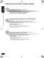
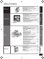
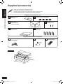
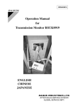
Operating Instructions Home Theater Audio System Model No. SC-HTR310 If you have any questions contact 1-800-211-PANA (7262) Dear customer Thank you for purchasing this product. For optimum performance and safety, please read these instructions carefully. Before connecting, operating or adjusting this product, please read the instructions completely. Please keep this manual for future reference. P SC-HTR310 (RQTX0165-P) - 14.07.08.indd 1 RQTX0165-1P 7/16/2008 1:51:03 PM CAUTION RISK OF ELECTRIC SHOCK DO NOT OPEN CAUTION: TO REDUCE THE RISK OF ELECTRIC SHOCK, DO NOT REMOVE SCREWS. NO USER-SERVICEABLE PARTS INSIDE. REFER SERVICING TO QUALIFIED SERVICE PERSONNEL. The lightning flash with arrowhead symbol, within an equilateral triangle, is intended to alert the user to the presence of uninsulated “dangerous voltage” within the product's enclosure that may be of sufficient magnitude to constitute a risk of electric shock to persons. WARNING: TO REDUCE THE RISK OF FIRE, ELECTRIC SHOCK OR PRODUCT DAMAGE, * DO NOT EXPOSE THIS APPARATUS TO RAIN, MOISTURE, DRIPPING OR SPLASHING AND THAT NO OBJECTS FILLED WITH LIQUIDS, SUCH AS VASES, SHALL BE PLACED ON THE APPARATUS. * USE ONLY THE RECOMMENDED ACCESSORIES. * DO NOT REMOVE THE COVER (OR BACK); THERE ARE NO USER SERVICEABLE PARTS INSIDE. REFER SERVICING TO QUALIFIED SERVICE PERSONNEL. The socket outlet shall be installed near the equipment and easily accessible. The mains plug of the power supply cord shall remain readily operable. To completely disconnect this apparatus from the AC Mains, disconnect the power supply cord plug from AC receptacle. The exclamation point within an equilateral triangle is intended to alert the user to the presence of HDMI, the HDMI logo and High-Definition Multimedia important operating and maintenance Interface are trademarks or registered trademarks of (servicing) instructions in the literature HDMI Licensing LLC. accompanying the appliance. HDAVI Control™ is a trademark of Matsushita Electric Industrial Co., Ltd. -If you see this symbolInformation on Disposal in other Countries outside the European Union This symbol is only valid in the European Union. If you wish to discard this product, please contact your local authorities or dealer and ask for the correct method of disposal. EZ Sync™ is a trademark of Matsushita Electric Industrial Co., Ltd. VIERA Link™ is a trademark of Matsushita Electric Industrial Co., Ltd. Manufactured under license from Dolby Laboratories. Dolby, Pro Logic, and the double-D symbol are trademarks of Dolby Laboratories. “DTS” and “DTS Digital Surround” are registered trademarks of DTS, Inc. 2 RQTX0165 SC-HTR310 (RQTX0165-P) - 14.07.08.indd 2 7/16/2008 1:51:05 PM Digital signals that can be played on this system DVD etc. Multi-channel LPCM (Linear PCM) PCM (2-channel) CD, DVD audio etc. Blu-ray disc, DVD audio etc. (Signals with sampling frequencies of up to 96 kHz) (Signals with sampling frequencies of up to 48 kHz) Before use DVD etc. DTS Digital signals that can be played on this system Dolby Digital Note • Playback of the following signals is also available when you make HDMI connections. ( pages 17 and 28) – PCM signals with sampling frequencies of over 96 kHz – Multi-channel signals with sampling frequencies of over 48 kHz Depending on the connected equipment, the playback condition differs. (Playback may be impossible if not supported.) See operating instructions of playback equipment for more information. • See “Glossary” ( page 38) for more detailed information on each signal. FCC Note: This equipment has been tested and found to comply with the limits for a Class B digital device, pursuant to Part 15 of the FCC Rules. These limits are designed to provide reasonable protection against harmful interference in a residential installation. This equipment generates, uses and can radiate radio frequency energy and, if not installed and used in accordance with the instructions, may cause harmful interference to radio communications. However, there is no guarantee that interference will not occur in a particular installation. If this equipment does cause harmful interference to radio or television reception, which can be determined by turning the equipment off and on, the user is encouraged to try to correct the interference by one or more of the following measures: • • • • Reorient or relocate the receiving antenna. Increase the separation between the equipment and receiver. Connect the equipment into an outlet on a circuit different from that to which the receiver is connected. Consult the dealer or an experienced radio/TV technician for help. Any unauthorized changes or modifications to this equipment would void the user’s authority to operate this device. This device complies with Part 15 of the FCC Rules. Operation is subject to the following two conditions: (1) This device may not cause harmful interference, and (2) this device must accept any interference received, including interference that may cause undesired operation. Responsible Party: Panasonic Corporation of North America One Panasonic Way Secaucus, NJ 07094 Support Contact: Panasonic Consumer Electronics Company Telephone No.: 1-800-211-PANA (7262) 3 RQTX0165 SC-HTR310 (RQTX0165-P) - 14.07.08.indd 3 7/16/2008 1:51:05 PM Before use Setting up your Home Theater system Step 1 Installing the rack ( pages 10 to 15) Setting up your Home Theater system After you have installed the rack, attach the glass top panel, shelf and glass doors. Step 2 Connecting the television and DVD player ( page 16) (Peripheral equipment and cables are not included unless otherwise mentioned.) Recommended TV size: 50 inches or less Basic connection ( page 16) Connect with an HDMI cable for high-quality audio and video. This connection requires HDMI terminals on both the television and the DVD recorder. ( page 17) Step 3 Enjoying movies and music ( pages 24 to 27) Enjoy surround sound with DVDs, TV, and other sources. This system has built-in speakers. Do not connect other speakers with the front speakers, center speaker and subwoofer. If you connect other speakers, the sound will not be produced with proper characteristics and malfunction may occur. 4 RQTX0165 SC-HTR310 (RQTX0165-P) - 14.07.08.indd 4 7/16/2008 1:51:05 PM Table of contents Before use Before use Digital signals that can be played on this system ................................................ 3 Setting up your Home Theater system ......... 4 Supplied accessories ..................................... 6 Control guide .................................................. 7 Remote control preparation .......................... 9 Installing and assembling the rack ............. 10 Home Theater connections ......................... 16 Connection Connection Basic connections............................................... 16 Connecting equipment with HDMI terminal (TV, DVD recorder, etc.) ............................................. 17 Connecting with digital terminal-mounted equipment .......................................................... 18 Connecting with VCR .......................................... 19 Other connections ........................................ 20 Connecting a set top box (cable or satellite) ... 20 Connecting a combination DVD recorder/VCR ... 21 AC power supply connection ...................... 22 Checking speaker output............................. 23 Enjoying movies and music ........................ 24 Sound field .......................................................... 26 Using the VIERA Link “HDAVI ControlTM” .. 28 Functions and settings ................................ 29 Reference Play Error messages ............................................ 35 Specifications ............................................... 35 Troubleshooting guide................................. 36 Product Service ............................................ 37 Glossary ........................................................ 38 Maintenance .................................................. 38 Limited Warranty .......................................... 39 Reference Play Using “WHISPER MODE SURROUND”............. 29 Using “GAME” .................................................... 29 Muting .................................................................. 29 Adjusting speaker output .................................. 29 REAL CENTER function ..................................... 30 Adjusting sound quality .................................... 30 Adjusting the balance ........................................ 30 Reducing standby power consumption (Standby mode) .................................................. 31 Setting VIERA Link “HDAVI Control” to “OFF ” ... 31 Adjusting the time lag by delaying audio output when pictures on TV arrives after sounds ........................................................ 31 Switching between dual sounds ....................... 32 Clear audio at low volume ................................. 32 Switching the attenuator ................................... 32 Setting input signals .......................................... 33 Reset (factory settings) ..................................... 33 When other equipment (mini component system, AV amp, etc.) manufactured by Panasonic operate ............................................. 34 5 RQTX0165 SC-HTR310 (RQTX0165-P) - 14.07.08.indd 5 7/16/2008 1:51:07 PM Supplied accessories Before use Please check and identify the supplied accessories. Use numbers when asking for replacement parts. (Product numbers correct as of June 2008. These may be subject to change.) To order accessories, refer to “Accessory Purchases” on page 39. Supplied accessories for rack Supplied accessories 1 Glass top panel (RXQ1618) 4 Caster stoppers (TBLB3008) 2 Glass doors 1 x Left (RXQ1607) 1 x Right (RXQ1608) 2 Screws (XTW4+16AFJK) Left side 2 Shelves (RKQ2G0004-K) Right side 8 Moulded dowels (RMQ1649) Supplied accessories for amplifier 1 AC power supply cord (K2CB2CB00021) 2 Batteries 1 Remote control (N2QAYB000288) Packing plan Glass top panel Glass doors Shelf (Dotted line) Other supplied accessories Batteries Remote control Rack 6 RQTX0165 SC-HTR310 (RQTX0165-P) - 14.07.08.indd 6 7/16/2008 1:51:11 PM Control guide Before use This system (Front view) Control panel (display) Center speaker Front speaker (right) Subwoofer (left) Control guide Front speaker (left) Subwoofer (right) Caster (Rear view) Rear panel Cut-outs Amplifier Cut-outs 7 RQTX0165 SC-HTR310 (RQTX0165-P) - 14.07.08.indd 7 7/16/2008 1:51:12 PM Control guide Before use Control panel For adjusting volume ( page 24) VOLUME Control guide Standby/on switch ( pages 22 to 24) ゲーム ( サウン ド ) Standby indicator ( page 22) WHISPER MODE INPUT SURROUND SELECTOR “INPUT SELECTOR” switch ( page 24) For using “WHISPER MODE SURROUND” ( page 29) Display When input signal is fixed to PCM ( page 33) When input signal is digital PCM DIGITAL INPUT DIGITAL DTS VS SFC PL When input signal is fixed to DTS ( page 33) Digital surround signal/Sound field ( below, pages 26 and 27) General display DIGITAL DTS VS SFC : : : : Dolby Digital sources DTS sources When Dolby Virtual Speaker is working When you are using an SFC mode : When Dolby Pro Logic decoder is being used (When using Dolby Virtual Speaker on 2 channel stereo source) PLⅡ Amplifier AC inlet ( page 22) Speaker terminals Exhaust hole (Cooling fan) Digital input terminal ( pages 17 to 21 and 28) Audio input terminal ( pages 16, 17, 19 and 21) HDMI terminal ( pages 17 and 28) Speaker terminals The speakers are already connected. Do not touch the connectors unless absolutely necessary. If the connectors become disconnected, refer to the illustrations below for connection. Connector connection Green Purple 8 Purple Green Red White White Red How to attach the connectors Terminal block Connector Make sure the color on the connector indicates the same as corresponding terminal and insert the connector straight all the way. RQTX0165 SC-HTR310 (RQTX0165-P) - 14.07.08.indd 8 7/16/2008 1:51:16 PM Before use Input mode and remote control mode buttons ( pages 24, 25 and 34) Standby/on button ( pages 23 to 25) Test signal output ( page 23) Adjusting speaker output ( pages 23 and 29) For using “WHISPER MODE SURROUND” ( page 29) For adjusting the volume ( pages 23 to 25) For using “GAME” ( page 29) Control guide/Remote control preparation OR” 24) Remote control Muting ( page 29) For adjusting settings/For activating settings ( pages 29 to 34) To enter setup mode ( pages 29 to 34) For returning to the previous menu ( pages 29 to 34) For selecting or cancelling Dolby Virtual Speaker, Dolby Pro Logic and SFC mode ( pages 26 and 27) Remote control preparation Inserting the batteries Press on the tab to open. (R6/LR6, AA) Insert so the poles (+ and –) match those in the remote control. Do not: • mix old and new batteries. • use different types at the same time. • take apart or short circuit. • attempt to recharge alkaline or manganese batteries. • use batteries if the covering has been peeled off. Mishandling of batteries can cause electrolyte leakage which can severely damage the remote control. Remove the batteries if the remote control is not going to be used for a long period of time. Store in a cool, dark place. CAUTION Danger of explosion if battery is incorrectly replaced. Replace only with the same or equivalent type recommended by the manufacturer. Dispose of used batteries according to the manufacturer’s instructions. • Do not use rechargeable type batteries. • Do not heat or expose to flame. • Do not leave the batteries in an automobile exposed to direct sunlight for a long period of time with doors and windows closed. Using the remote control Remote control signal sensor VOLUME WHISPER MODE INPUT SURROUND SELECTOR Within 7 meters (23 feet) at the front (actual distance depends on the angle) Transmission window Note • Do not place an object between the signal sensor and the remote control. • Do not place the signal sensor under direct sunlight or the strong light of a fluorescent lamp. • Keep the transmission window and the system’s sensor free from dust. 9 RQTX0165 SC-HTR310 (RQTX0165-P) - 14.07.08.indd 9 7/16/2008 1:51:18 PM Installing and assembling the rack Shelf assembly ( page 12) Glass door assembly ( page 15) Connection Glass top panel assembly ( page 12) Speaker net Setting the caster stoppers ( page 14) Installing each (DVD player/Blu-ray Disc player/DVD recorder page 13) equipment (TV page 13) Installation Installing and assembling the rack At least 2 people are necessary for installation. Use a Phillips-head screwdriver. (Do not use a powered screwdriver.) Choose a stable location for installation. Handle the glass top panel and glass doors with enough care. Setup example This system This system This system • Make sure to place the rack on a flat, stable surface so there is no danger of it falling over. Take enough safety measures to prevent the television from falling down. • You can install this system so that it is flush with the wall at either the sides or back, but you will require some space for working during setup and connection. • Do not place in front of curtains as they may obstruct the system’s exhaust hole. • Avoid pressing on the speaker nets during installation. • If the surface of the wooden floor is soft, the caster mark may remain. • See page 11 for removing casters. Caution • Use the supplied speakers only with our home theater audio system. Failure to do so can damage the amplifier and speakers, and can cause fire. • Consult a qualified service person if damage occurs or if performance worsens. 10 RQTX0165 SC-HTR310 (RQTX0165-P) - 14.07.08.indd 10 7/16/2008 1:51:20 PM Removing casters • Remove casters at unstable places. (thick-piled carpet, uneven floor, etc.) • Spread soft cloth on the floor and tip the rack back to remove the casters. • Hold and pull to remove. • At least 2 people are necessary for removing casters. • Make sure that at least 2 people hold the bottom plate when moving the rack after removing the casters. See the following instructions about how to lift the rack. • Do not put anything on and in the rack when removing casters. Do not put the included glass top panel either. (Bottom plate) Front side Caster Back side Hold and pull. How to lift the rack Lift the back side of the top board and insert your hand to the bottom of the back side. Insert your hand to the bottom of the front side. Lift the rack horizontally using your both hands. Connection Soft cloth, etc. Front side Installing and assembling the rack Back side 11 RQTX0165 SC-HTR310 (RQTX0165-P) - 14.07.08.indd 11 7/16/2008 1:51:30 PM Installing and assembling the rack Glass top panel assembly 1 Adjust the included glass top panel so that it lines up with the protrusion on the back of the rack. Glass top panel Nonslip sheet Protrusion Sticker Connection • The glass top panel has the front side and back side. Face up the front side with the sticker. • The nonslip sheet has been put on the top panel of the rack. Do not remove the sheet when installing the glass top panel. 2 Put the glass panel down slowly to make sure its aligned with the rear of the top panel of the rack (as shown in the diagram). Top panel of the rack (Side view) Glass top panel Top panel of the rack Note Installing and assembling the rack Lift up and down slowly not to make an impact on the glass. Shelf assembly 1 Insert the moulded dowel (included) into the dowel hole on one side. Hole Moulded dowel 2 Insert the shelf (included) at an angle and adjust it so that the shelf groove is attached to the molded dowel. 3 Hold the shelf, insert the moulded dowel into the dowel hole on the other side. Set the shelf horizontally. Groove (Under the shelf) Shelf • The height of the shelf can be adjusted at 3 different levels. • Change the position of the dowels to move the shelf up or down. • Insert the moulded dowel not to lose even when the shelf is not set. UNIT: mm (inches) Dowel position Upper Middle Lower Upper shelf 101 (3 31/32”) 131 (5 5/32”) 161 (6 11/32”) H Lower shelf 101 (3 31/32”) 71 (2 25/32”) 41 (1 5/8”) Compartment W 448 (17 5/8”) (both L and R) D 354 (13 15/16”) 12 RQTX0165 SC-HTR310 (RQTX0165-P) - 14.07.08.indd 12 7/16/2008 1:51:32 PM Installing a DVD player/Blu-ray Disc player/DVD recorder or other equipment on the shelf (Please also refer to the other equipment’s operating instructions.) 2 (Rear view) Cut-outs Big cut-outs Connection • Refer to pages 16 to 21 for connections with other equipment. • If the operating instructions of the equipment require heat release or ventilation, remove the cut-out on the back panel to secure ventilation. • When setting equipment with the exhaust hole on the side, follow the operating instruction of the equipment before setting. Push the black-circled point. Small cut-outs Pull out the bundled cords of stored equipment from the cut-outs for connection. Note (Side view in cross section) Shelf top (Front view) • Do not put equipment weighing more than 12 kg (26.5 lbs) on the upper shelf or more than 20 kg (44.1 lbs) on the lower shelf. • Image interference may occur if you put a DVD recorder, etc. on the upper shelf. Put it on the lower shelf if this occurs. • Depending on the equipment to install, the cables The lowest level (on the floor panel) may not be connected. To install the equipment, adjust the height of the shelf Shelf top (dimension ): 348 mm (13 11/16”) 13(Maximum depth of equipment when the big cut-outs part on the to the position where the cables come out. back panel is opened) • If you set on the lowest level (on the floor panel), the 1 equipment with long depth may not be set properly or Shelf top (dimension ): 255 mm (10 /16”) (Maximum depth of equipment when the small cut-outs part on the equipment cord may not be taken out. the back panel is opened) • When installing equipment, refer to the table for “Shelf The lowest level (on the floor panel) (dimension ): assembly” on page 12. 255 mm (10 1/16”) (Maximum depth of equipment) Installing the television (Please also refer to the television’s operating instructions.) Installing and assembling the rack 1 Press the cut-out on the back panel using your thumb etc. with force to remove it for wiring after installing the equipment. Recommended: 50 inches or less Place the television (with stand attached) in the center of the rack. Note • Lift the television when placing it on the rack. Dragging it may damage the top panel. (For details, refer to the television’s operating instructions.) • If the television stand adheres to the glass top panel too tight to remove, lift the stand inserting a flat and thin object. This may help removing the stand. • Install the rotary television stand not to run over the rack even if it rotates. Television stand 13 RQTX0165 SC-HTR310 (RQTX0165-P) - 14.07.08.indd 13 7/16/2008 1:51:35 PM Installing and assembling the rack Setting the caster stoppers Set the caster stoppers (included) under the casters to fix this system and prevent from moving. • When setting the caster stoppers, match the front side of caster with the arrow of the caster stopper. (Caster stopper position) Set the caster stoppers under 4 casters circled with the dotted line of figure below. Front side Front Connection Caster stopper (Bottom side) Arrow • Lift the rack to remove caster stoppers. See page 11 about how to lift the rack. Stabilising the television Attach the television to the rack to prevent it from falling over. Installing and assembling the rack Fixing to the rack (Setup example) • Attach the fall-prevention band etc. supplied with TV using the included screws as illustrated at right. (If the fall-prevention band is not supplied with TV, use a commercially available band to fix.) Attach the fall-prevention band to the prepared hole in the center of the underside of the top board. If the hole is not positioned at a suitable place, drill approx. 2 mm (3/32”) hole on the underside and attach the band with the screw. • If you fasten the screw too tightly, it goes around in circles and the TV cannot be fixed. Fixing to the wall • Use commercially available screws, strong string or chain suitable for materials of the wall or pillar to fix to the solid parts. • Walls and pillars must be strong enough to support the weight of TV. Ask installation personnel for more information. • Fix 2 parts at both left and right. Fall-prevention band Prepared screw hole Screw (included) (Setup example) The illustration is an example. The shape may differ from the actual product. 14 RQTX0165 SC-HTR310 (RQTX0165-P) - 14.07.08.indd 14 7/16/2008 1:51:37 PM Glass door assembly Remove 4 screws from the glass holder using a Phillips-head screwdriver and take out the board. Board • Before taking out the board, remove the tape fixing the glass holder. • Use the Phillips-head screwdriver that matches the screw size. 2 Phillips-head screwdriver Glass holder Insert the glass door (included) to the glass holder firmly and tighten the 2 screws in front tentatively. • The illustration at right shows how to fix the left glass door. • One side of the magnet catch has a hole. This is the inner side of the glass. • The slippage prevention sheet is pasted on the glass holder inserting part on the surface of the glass door. Fix as it is. Screw Magnet catch Screw Hole Inner side of glass Connection 1 Slippage prevention sheet 3 Close the glass door to adjust the height and gap on both sides. Open the glass door so it does not misalign and tighten 2 screws in front with the Phillips-head screwdriver. Inner side of glass Phillips-head screwdriver Screw Screw 4 Tighten 2 screws at the back firmly. • Install the other glass door in the same way. Inner side of glass Phillips-head screwdriver Screw Installing and assembling the rack Screw 15 RQTX0165 SC-HTR310 (RQTX0165-P) - 14.07.08.indd 15 7/16/2008 1:51:39 PM Home Theater connections Basic connections Connection cable Stereo connection cable (not included) • Refer to the operating instructions for the equipment you are connecting for the correct type of video cable. Connection TV Connect the video directly from the other equipment to the television. Home Theater connections Audio out R L Use this connection so audio from the equipment can be heard through the television’s speakers even if this system is in standby mode. VIDEO IN AUDIO IN Amplifier Video cable Audio cable DVD player etc. VIDEO OUT AUDIO OUT Reduce the volume on the television and select “TV ” after you have done connections as above if you want to use this system. 16 RQTX0165 SC-HTR310 (RQTX0165-P) - 14.07.08.indd 16 7/16/2008 1:51:40 PM • Turn off all components before making any connections. • To connect equipment, refer to the appropriate operating instructions. Connecting equipment with HDMI terminal (TV, DVD recorder, etc.) Connection cable Stereo connection cable (not included) HDMI cable (not included) Optical fiber cable (not included) HDMI cable notes • Use a Panasonic HDMI cable for best results. Make the connection either or according to the suitability for your equipment. HDMI input Connection Audio out R L TV Digital audio out (optical) Note the shape and fit it correctly into the terminal. Do not bend! Amplifier Home Theater connections Connecting the optical fiber cable io e Blu-ray Disc player/DVD recorder, etc. HDMI Video/Audio out 17 RQTX0165 SC-HTR310 (RQTX0165-P) - 14.07.08.indd 17 7/16/2008 1:51:42 PM Home Theater connections Connecting with digital terminal-mounted equipment Connection cable Optical fiber cable (not included) Coaxial cable (not included) • Refer to the operating instructions for the equipment you are connecting for the correct type of video cable. Connection TV Connect the video directly from the other equipment to the television. Digital audio out (optical) VIDEO IN Use this connection so audio from the equipment can be heard through the television’s speakers even if this system is in standby mode. AUDIO IN Home Theater connections Connecting the optical fiber cable Amplifier Note the shape and fit it correctly into the Do not terminal. bend! Video cable Audio cable DVD player etc. Digital audio out (optical) Digital audio out (coaxial) VIDEO OUT AUDIO OUT Make the connection either or according to the suitability for your equipment. 18 RQTX0165 SC-HTR310 (RQTX0165-P) - 14.07.08.indd 18 7/16/2008 1:51:44 PM • Turn off all components before making any connections. • To connect equipment, refer to the appropriate operating instructions. Connecting with VCR Connection cable Stereo connection cable (not included) Optical fiber cable (not included) Digital audio out (optical) Connect the video directly from the other equipment to the television. Use this connection so audio from the equipment can be heard through the television’s speakers even if this system is in standby mode. VIDEO IN AUDIO IN Connecting the optical fiber cable Note the shape and fit it correctly into the Do not terminal. bend! Amplifier Video cable Audio cable Home Theater connections TV Connection • Refer to the operating instructions for the equipment you are connecting for the correct type of video cable. VCR etc. VIDEO OUT AUDIO OUT R L Audio out 19 RQTX0165 SC-HTR310 (RQTX0165-P) - 14.07.08.indd 19 7/16/2008 1:51:45 PM Other connections Connecting a set top box (cable or satellite) Connection cable Coaxial cable (not included) Optical fiber cable (not included) Connection • Refer to the operating instructions for the equipment you are connecting for the correct type of video cable. Connect the video directly from the other equipment to the television. Other connections VIDEO IN TV Use this connection so audio from the equipment can be heard through the television’s speakers even if this system is in standby mode. Digital audio out (optical) AUDIO IN Amplifier Video cable Audio cable Connecting the optical fiber cable Note the shape and fit it correctly into the terminal. VIDEO OUT Do not bend! AUDIO OUT Digital audio out (optical) Cable box or satellite receiver, etc. Digital audio out (coaxial) DVD player etc. 20 RQTX0165 SC-HTR310 (RQTX0165-P) - 14.07.08.indd 20 7/16/2008 1:51:47 PM • Turn off all components before making any connections. • To connect equipment, refer to the appropriate operating instructions. Connecting a combination DVD recorder/VCR Connection for equipment with DVD/VCR terminal. Connection cable Stereo connection cable (not included) Optical fiber cable (not included) TV Connect the video directly from the other equipment to the television. Digital audio out (optical) AUDIO IN Other connections VIDEO IN Use this connection so audio from the equipment can be heard through the television’s speakers even if this system is in standby mode. Connecting the optical fiber cable Note the shape and fit it correctly into the terminal. Do not bend! Video cable Amplifier Combination DVD recorder/VCR R L Audio out DVD/ VCR out terminal Digital audio out (optical) DVD out terminal Connection • Refer to the operating instructions for the equipment you are connecting for the correct type of video cable. VIDEO OUT Audio cable AUDIO OUT Note See page 25 for playback. 21 RQTX0165 SC-HTR310 (RQTX0165-P) - 14.07.08.indd 21 7/16/2008 1:51:48 PM AC power supply connection Connect AC power supply cord after all other cables are connected. AC power supply connection Connection Amplifier AC power supply cord (included) Household AC outlet (AC 120 V, 60 Hz) Note • The included AC power supply cord is for use with this system only. Do not use it with other equipment. • Also, do not use AC power supply cord for other equipment with this system. Conserving power This system consumes a small amount of power, even when it is in standby mode (approx. 0.7 W). To save power when the system is not to be used for a long time, unplug it from the household AC outlet. You will need to reset some memory items after plugging in this system. “Standby” indicator Standby/on switch [8] Press to switch the unit from on to standby mode or vice versa. In standby mode, the unit is still consuming a small amount of power. Standby indicator VOLUME WHISPER MODE INPUT SURROUND SELECTOR Standby/on switch Standby indicator [^] When the unit is connected to the AC mains supply, this indicator lights up in standby mode and goes out when the unit is turned on. 22 RQTX0165 SC-HTR310 (RQTX0165-P) - 14.07.08.indd 22 7/16/2008 1:51:49 PM Checking speaker output You can check audio output with a test signal 1. Press to turn on the system. 2. Press to output the test signal. Speaker 3. Press to adjust the volumes of • Test signal is output from one speaker at a time for two seconds in the following order. L (Front left) → C (Center) → R (Front right) → SUBW (Subwoofer) 4. Press to stop the test signal. Connection front speakers to the normal listening level. Checking speaker output Note Check connections when the speaker does not have output the test signal. ( page 8) Adjusting speaker output If you feel the output of the center speaker and subwoofer are not balanced with front speakers adjust the speaker output according to your preference. 1. Output the test signal. ( above step 1 to 3) 2. Press to select a speaker for adjustment. SUBW (Subwoofer) → C (Center) 3. Press to adjust each speaker’s output level. • The test signal comes from the speaker being adjusted. • Test signal is output again in above order 2 seconds after adjustment. 4. Press to stop the test signal. Adjustment range: SUBW: C: OFF, MIN, 1 to 19, MAX − 6 to + 6 Note • To adjust the front speaker volumes, press [VOL –, +]. To adjust the volume balance of left and right front speakers, see “Adjusting the balance”. ( page 30) • When you select “OFF ” for subwoofer adjustment, there is no output from the subwoofer. • Even if you adjust each channel level in this adjustment, each channel level setting in each SFC mode does not change. • When you make this adjustment, Dolby Virtual Speaker functions. When playing 2-channel sources, Dolby Pro Logic also works in conjunction. ( pages 26 and 27) • You can adjust the speaker level while playing movies and music. ( page 29) 23 RQTX0165 SC-HTR310 (RQTX0165-P) - 14.07.08.indd 23 7/16/2008 1:51:53 PM Enjoying movies and music Preparation Turn on the television and switch its input to match the connection (HDMI, for example) using Enjoying movies and music television remote control. Play Control panel Operation on the control panel 1 Turn on the system 2 Select the source. Press VOLUME ゲーム ( サウン ド ) Press (The input source switches each time you press the button.) INPUT SELECTOR WHISPER MODE INPUT SURROUND SELECTOR TV BD/DVD (factory setting) AUX 1 AUX 2 AUX 3 Control panel 3 4 : TV : Blu-ray Disc player/ DVD recorder : AUX1 terminal : AUX2 terminal : AUX3 terminal Start play on the other equipment. Adjust the volume. Press VOLUME 24 RQTX0165 SC-HTR310 (RQTX0165-P) - 14.07.08.indd 24 7/16/2008 1:51:56 PM See page 3 for digital signals that can be played on this system. 1 To turn on the system 2 To select the source or Press one of these buttons. (factory setting) TV BD/DVD AUX 1 AUX 2 AUX 3 or Enjoying movies and music Press the button. : TV : Blu-ray Disc player/ DVD recorder : AUX1 terminal : AUX2 terminal : AUX3 terminal “AUX 1”, “AUX 2” and “AUX 3” switch every time you press [AUX]. 3 4 Start play on the other equipment. You can enjoy the variety of surround effects. ( pages 26 and 27) To adjust the volume Press the buttons. 0 (Min) to 50 (Max) Play After playback, reduce the volume level and turn off. Note • Depending on the playback source, you may feel the volume of the subwoofer or center speaker is not balanced with the volume of the front speakers. In this case, you can adjust the speaker volume during playback. ( page 29) • Even if you switch input to sources other than “BD/DVD ”, images (or audio) of the equipment connected to BD/DVD terminal are output from TV output terminal. Enjoying images and audio when this system is OFF • When image equipment such as TV and recorder is connected to this system via HDMI ( page 17), images/audio signals from the recorder go through this system and are transmitted to TV even if this system is turned off. (Standby through function) This is convenient to enjoy only with TV speaker. • Images recorded with x.v.Color ( page 38) are also supported. Note When you turn this system off, the audio/video signals from a recorder connected to this system’s BD/DVD HDMI input terminal are output through the television, even if you have set input on this system to anything other than “BD/DVD ”. (The selector returns to the previous setting when you turn this system on again.) Playing a DVD recorder with built-in VCR If the equipment has the output terminal specifically for DVD/VHS, select input as described in step 2 above. • To enjoy DVD: select “AUX 1 ”. • To enjoy video: select “AUX 3 ”. 25 RQTX0165 SC-HTR310 (RQTX0165-P) - 14.07.08.indd 25 7/16/2008 1:51:59 PM Enjoying movies and music The effects for sound field differ depending on input source. Select the mode you prefer. Sound field Dolby Virtual Speaker You can enjoy surround effects just like 5.1 channel. (Dolby Pro Logic sources.) Dolby Virtual Speaker has the following modes. works with video cassettes or CD stereo REFERENCE (Standard mode) Standard sound effect. WIDE (Wide mode) Broadens the effect to the left and right. Enjoying movies and music Dolby Pro Logic You can enjoy 2-channel sources including CD with the surround effect. SFC (Sound Field Control) You can add presence and spread to surround sound according to your choice when you use SFC with Dolby Digital, DTS, stereo sources (video, CD, etc.). SFC has the following modes. Play MUSIC MOVIE LIVE Imparts the reflection and spread of a large concert hall. DRAMA Best suited for dialogs in drama movies. POP/ROCK Best suited for dynamic sound such as pop and rock music. ACTION Best suited for action movies with impact. VOCAL Best suited to enhance vocals. SPORTS Enjoy a feeling like being at a live sporting event. JAZZ Enjoy sound reflections as if you were in a small Jazz club. MUSICAL Enjoy a feeling like being at a live musical performance. DANCE Enjoy a dance hall like audio effect. GAME Enjoy games with greater audio impact. MONO Best suited for older monaural audio movies. Note • See page 8 about how to display the surround digital signal/sound field. PL ]. • If the input source is 2-channel, Dolby Virtual Speaker also works in conjunction by pressing [ • SFC is not available for multi-channel LPCM signal. • You cannot use Dolby Virtual Speaker, Dolby Pro Logic and SFC when the source contains PCM signals with sampling frequencies of over 48 kHz. They are automatically cancelled if those signals are input. To use the effect when playing back other sources, press [ VIRTUAL SPEAKER], [ PL ] or [SFC MUSIC, MOVIE] again to select. • You can also press [GAME] on the remote control to select “GAME ” mode ( above) of SFC. ( page 29) • When sound field is cancelled, the previous condition before sound field is cancelled returns by changing input source, turning the system ON/OFF, or switching input. • This system supports 7.1 channel LPCM signals. You can enjoy wider sound field effects when playing back. The following display appears when 7.1 channel LPCM signals arrive. 26 RQTX0165 SC-HTR310 (RQTX0165-P) - 14.07.08.indd 26 7/16/2008 1:52:00 PM Using Dolby Virtual Speaker • The mode switches each time you press the button. ( page 26) Press Using Dolby Pro Logic Press Using SFC (Sound Field Control) You can enjoy by adding your favourite surround effect in addition to the Dolby Virtual Speaker ( above) effect. • The mode switches each time you press the button. ( page 26) Press To cancel SFC mode Enjoying movies and music VS PL Press Play Cancelling sound field Press • The surround effects disappear for 2-channel sources such as CD and TV. • The surround digital signals which input sources are Dolby digital or DTS and multichannel LPCM signals are converged to 3.1-channel and the signals are output from the left and right front speakers, center speaker and subwoofer. 27 RQTX0165 SC-HTR310 (RQTX0165-P) - 14.07.08.indd 27 7/16/2008 1:52:02 PM Using the VIERA Link “HDAVI ControlTM” Using the VIERA Link “HDAVI ControlTM” What is VIERA Link “HDAVI Control” ? VIERA LinkTM is a new name for EZ SyncTM. VIERA Link “HDAVI Control” is a convenient function that offers linked operations of this system, and a Panasonic TV (VIERA) or DVD recorder (DIGA) under “HDAVI Control”. You can use this function by connecting the equipment with the HDMI cable. See the operating instructions for connected equipment for operational details. • VIERA Link “HDAVI Control”, based on the control functions provided by HDMI which is an industry standard known as HDMI CEC (Consumer Electronics Control), is a unique function that we have developed and added. As such, its operation with other manufacturers’ equipment that supports HDMI CEC cannot be guaranteed. • This system supports “HDAVI Control 3” function. “HDAVI Control 3” is the newest standard (current as of December, 2007) for Panasonic’s HDAVI Control compatible equipment. This standard is compatible with Panasonic’s conventional HDAVI equipment. • Please refer to individual manuals for other manufacturers’ equipment supporting VIERA Link function. You can enjoy the following by using the remote control of TV (VIERA) You can select “Speaker Selection” (“Home Cinema” or “TV”). Home Cinema: This system will be automatically turned on if it is in standby mode and the sound is from this system’s speaker. You can also adjust the volume level by using the volume control buttons. TV: TV speakers are active. When you switch off the TV (VIERA), this system automatically turns off. When VIERA Link “HDAVI Control” compatible recorder (DIGA) is connected with HDMI cable, the recorder (DIGA) also turns off. Note • When you operate the TV (VIERA) such as selecting a channel this system’s input selector will automatically switch to “TV” • When you operate DIGA DVD recorder, this system’s input selector will automatically switch to “BD/DVD ”. • To operate other functions, use this system’s remote control. Connection Play Connect your home theater equipment (VIERA Link “HDAVI Control” compatible VIERA television and DIGA DVD recorder) with an HDMI cable. • It is recommended that you use Panasonic’s HDMI cable. Non-HDMI-compliant cables cannot be utilised. Recommended part number: RP-CDHG10 (1.0 m/3.3 ft), RP-CDHG15 (1.5 m/4.9 ft), RP-CDHG20 (2.0 m/6.6 ft), RP-CDHG30 (3.0 m/9.8 ft), RP-CDHG50 (5.0 m/16.4 ft), etc. • Only with HDMI cable connection, you cannot enjoy TV sounds on this system. Connect TV to this system with the optical fiber cable to enjoy TV sound. Digital audio out (optical) Amplifier HDMI OUT HDMI IN TV (VIERA) DVD recorder (DIGA) Setup Switch on all your equipment. Switch on your television (VIERA). Switch television (VIERA) input to HDMI terminal that this system is connected to. Ensure that this system’s input is set to “BD/DVD ” in order to view pictures from DIGA correctly. Note This setup should be done each time when the following conditions occur: • for the first time • when adding or reconnecting equipment • when changing setup When not using this function Set VIERA Link “HDAVI Control” to “OFF ”. ( page 31) 28 RQTX0165 SC-HTR310 (RQTX0165-P) - 14.07.08.indd 28 7/16/2008 1:52:04 PM Functions and settings Press To cancel Press again. If cancelled, “W.S. OFF ” is displayed. You can enjoy dynamic surround effect even when the sound volume level is low. VOLUME ゲーム ( サウン ド ) WHISPER MODE INPUT SURROUND SELECTOR Press [WHISPER MODE SURROUND] indicator • When this function is on, [WHISPER MODE SURROUND] indicator lights up on the control panel. Note • WHISPER MODE SURROUND cannot be used in the following cases. When Dolby Virtual Speaker is off If the above setting is made when this function is on, [WHISPER MODE SURROUND] indicator disappears and this function temporarily becomes off. Using “GAME” Press Enjoy gaming with more impact. • “GAME ” mode ( pages 26 and 27) in SFC is selected. Muting Press Functions and settings Using “WHISPER MODE SURROUND” This setting can be made on control panel as well. Control panel To cancel Press again. If cancelled, SFC’s effect itself is cancelled. Press again. “MUTING IS ON ” scrolls To cancel across the display while • Muting is cancelled when you switch the system to standby. the volume is muted. • Muting is also cancelled when you adjust the volume. to select a speaker for adjustment. Play 1 Press (The speaker is switched each time you press the button.) SUBW (Subwoofer) → C (Center) Adjusting speaker output 2 Press to adjust each speaker’s Depending on the output level. playback source, you Adjustment range: SUBW: OFF, MIN, may feel the volume of 1 to 19, MAX the subwoofer or center − 6 to +6 C: speaker is not balanced with the volume of the Note front speakers. In this case, you can adjust the • To adjust the volume balance of the front speakers, see speaker volume during “Adjusting the balance”. ( page 30) playback. • There is no output from the subwoofer if you select “OFF”. • If the sound is distorted, lower the level. • You cannot adjust the output level of speakers if the speakers’ audio output is set to off. ( pages 26 and 27) • You can adjust the speaker’s output level in SFC’s each mode respectively. ( pages 26 and 27) 29 RQTX0165 SC-HTR310 (RQTX0165-P) - 14.07.08.indd 29 7/16/2008 1:52:07 PM Functions and settings 1 Press and hold 2 Press REAL CENTER function Makes the dialog from the center speaker clearer when playing surround sources. Functions and settings Factory setting is “ON”. See right to set it “OFF”. for about 2 seconds. to select “REAL C.”. Press confirm. REAL C., BASS, TREBLE, BALANCE, HDMI, TV DELAY, DUAL PRG, DRCOMP, ATTENUATOR, REMOTE, INPUT MODE, RESET, EXIT Only appears when audio adjustment can be made. 3 Press to select “OFF”. ON, OFF • Select “EXIT” and confirm to finish the setup mode. Press to confirm. Factory setting: ON • The effect changes as soon as you select “ON” or “OFF” but you must press [OK] to confirm selection. 4 Press a few times to select Press confirm. “EXIT”. You can adjust the level of bass and treble. Play Input signals must be 2 channel of either analog or PCM. This setting is not displayed in other conditions. Make sure the above setting is made before setup this function. 1 Press and hold 2 Press Press confirm. to Press confirm. to Press confirm. to • Select “EXIT” and confirm to finish the setup mode. Only appears when audio adjustment can be made. 3 Press to adjust range. Adjustment range: –6 to +6 4 Press a few times to select “EXIT”. Return to previous menu/cancel. 2 Press You can adjust the balance of the front speakers. L: Front speaker (left) R: Front speaker (right) REAL C., BASS, TREBLE, BALANCE, HDMI, TV DELAY, DUAL PRG, DRCOMP, ATTENUATOR, REMOTE, INPUT MODE, RESET, EXIT 1 Press and hold Adjusting the balance for about 2 seconds. to select “BASS” or “TREBLE”. to Press Return to previous menu/cancel. Adjusting sound quality to “BALANCE ”. Press for about 2 seconds. Press confirm. to select REAL C., BASS, TREBLE, BALANCE, HDMI, TV DELAY, DUAL PRG, DRCOMP, ATTENUATOR, REMOTE, INPUT MODE, RESET, EXIT to • Select “EXIT” and confirm to finish the setup mode. Only appears when audio adjustment can be made. 3 Press to adjust the balance. 4 Press a few times to select “EXIT”. Return to previous menu/cancel. Press confirm. to Press confirm. to Use the bar as a guide. Press 30 RQTX0165 SC-HTR310 (RQTX0165-P) - 14.07.08.indd 30 7/16/2008 1:52:13 PM 1 Press and hold Reducing standby power consumption 2 Press for about 2 seconds. to select “HDMI”. REAL C., BASS, TREBLE, BALANCE, HDMI, TV DELAY, DUAL PRG, DRCOMP, ATTENUATOR, REMOTE, INPUT MODE, RESET, EXIT (Standby mode) Press confirm. to Press confirm. to Press confirm. to • Select “EXIT” and confirm to finish the setup mode. Standby through function ( pages 25 and 38) does not work in this mode if you have connected through the HDMI terminal. VIERA Link “HDAVI Control” ( page 28) will not function when this system is off. 3 Press to select “STNBY”. STNBY, CTRL 4 Press to select “OFF”. OFF : Standby power consumption reduced (approx. 0.3 W) ON : Normal standby power consumption 5 Press “EXIT”. a few times to select Return to previous menu/cancel. 1 Press and hold 2 Press Functions and settings Only appears when audio adjustment can be made. Factory setting: ON Press confirm. to Press confirm. to Press confirm. to Press confirm. to Press for about 2 seconds. to select “HDMI”. REAL C., BASS, TREBLE, BALANCE, HDMI, TV DELAY, DUAL PRG, DRCOMP, ATTENUATOR, REMOTE, INPUT MODE, RESET, EXIT • Select “EXIT” and confirm to finish the setup mode. 3 Press to select “CTRL”. STNBY, CTRL 4 Press to select “OFF”. OFF : When the operation is not linked ON : When the operation is linked 5 Press a few times to select “EXIT”. Return to previous menu/cancel. 1 Press and hold 2 Press Adjusting the time lag by delaying audio output when pictures on TV arrives after sounds Play Only appears when audio adjustment can be made. Setting VIERA Link “HDAVI Control” to “OFF” Factory setting: ON Press confirm. to Press confirm. to Press for about 2 seconds. to select “TV DELAY”. • Select “EXIT” and confirm REAL C., BASS, TREBLE, BALANCE, HDMI, TV DELAY, to finish the setup mode. DUAL PRG, DRCOMP, ATTENUATOR, REMOTE, INPUT MODE, RESET, EXIT Only appears when audio adjustment can be made. 3 Press to select setting. AUTO , OFF, 10, 20, 30, 40 For only combination with Panasonic TV (VIERA) Supporting HDAVI Control 3. 4 Press a few times to select “EXIT”. Return to previous menu/cancel. Press to confirm. Factory setting: AUTO Press confirm. Press to 31 RQTX0165 SC-HTR310 (RQTX0165-P) - 14.07.08.indd 31 7/16/2008 1:52:17 PM Functions and settings 1 Press and hold 2 Press for about 2 seconds. Press confirm. to select to “DUAL PRG”. • Select “EXIT” and confirm REAL C., BASS, TREBLE, BALANCE, HDMI, to finish the setup mode. TV DELAY, DUAL PRG, DRCOMP, ATTENUATOR, REMOTE, INPUT MODE, RESET, EXIT Only appears when audio adjustment can be made. Switching between dual sounds Functions and settings You can switch between dual sounds of 3 Press Dolby Digital signals. to select the sound. M1: Main audio, M2: Sub channel audio output, M1+M2: Main + Sub channel audio output 4 Press “EXIT”. a few times to select Return to previous menu/cancel. 1 Press and hold Clear audio at low volume Play Dynamic range compression for Dolby Digital 2 Press Press confirm. to for about 2 seconds. • Select “EXIT” and confirm REAL C., BASS, TREBLE, BALANCE, HDMI, TV DELAY, to finish the setup mode. DUAL PRG, DRCOMP, ATTENUATOR, REMOTE, INPUT MODE, RESET, EXIT Only appears when audio adjustment can be made. to select setting. OFF: Normal playback; STANDARD: The level recommended by the producer of the software for household viewing; MAX: The maximum allowable compression (recommended for night viewing) Return to previous menu/cancel. 1 Press and hold 2 Press for about 2 seconds. Press confirm. “ATTENUATOR”. REAL C., BASS, TREBLE, BALANCE, HDMI, TV DELAY, DUAL PRG, DRCOMP, ATTENUATOR, REMOTE, INPUT MODE, RESET, EXIT Only appears when audio adjustment can be made. 3 Press to select “ON”. ON, OFF 4 Press “EXIT”. to Press to select Press to confirm. Factory setting: OFF Press confirm. a few times to select “EXIT”. Switch the attenuator “ON ” when big sounds become distorted while playing an analog input source. to Press to select “DRCOMP”. It compresses the 3 Press dynamic range so that you can still hear dialog and leave the sound field unaffected. Use this function when you have to turn the volume down, such as late at 4 Press night. Switching the attenuator Press confirm. a few times to select Return to previous menu/cancel. to • Select “EXIT” and confirm to finish the setup mode. Press to confirm. Factory setting: OFF Press confirm. to Press 32 RQTX0165 SC-HTR310 (RQTX0165-P) - 14.07.08.indd 32 7/16/2008 1:52:19 PM 2 Press for about 2 seconds. to select “INPUT Press confirm. to Press confirm. to Most sources can be • Select “EXIT” and REAL C., BASS, TREBLE, BALANCE, HDMI, played with “AUTO ” MODE”. confirm to finish the TV DELAY, DUAL PRG, DRCOMP, ATTENUATOR, (factory setting). setup mode. REMOTE, INPUT MODE, RESET, EXIT However, in the Only appears when audio adjustment can be made. following cases, change the input signal to select source. 3 Press detection setting. Press to ● When the beginning confirm. TV, DVD, AUX1, AUX2 of the song is cut during playback of to select input signal. 4 Press Press to CD, set to “PCM ” confirm. (PCM FIX). AUTO : Automatic detection ● When the signal is PCM : PCM (from CDs) digital input fixed Factory setting: AUTO not detected during DTS : DTS digital input fixed playback of DTS ANLG (TV only): Fixes the input signal to analog sources, set to DIG (TV only): Fixes the input signal to digital “DTS ” (DTS FIX). ● You can fix the Repeat steps 3 and 4 to change setting. signal type (digital or analog) supplied by 5 Press a few times to select Press to TV. “EXIT”. confirm. When noise occurs, return the setting to “AUTO ”. Return to previous menu/cancel. 1 Press and hold Reset (factory settings) The operation settings for the system will be initialised to the settings made at the time of shipment. 2 Press Press Functions and settings 1 Press and hold for about 2 seconds. to select “RESET”. REAL C., BASS, TREBLE, BALANCE, HDMI, • Select “EXIT” and TV DELAY, DUAL PRG, DRCOMP, ATTENUATOR, confirm to finish the REMOTE, INPUT MODE, RESET, EXIT setup mode. Only appears when audio adjustment can be made. 3 Press to select “YES”. YES, NO Press confirm. to Play Setting input signals • All the settings are reset when you select “YES” and the input selector automatically switches to “BD/DVD”. • If you select “NO”, you will return to step 2. To exit setup mode, press [RETURN] a few times to display “EXIT”, and then press [OK]. 33 RQTX0165 SC-HTR310 (RQTX0165-P) - 14.07.08.indd 33 7/16/2008 1:52:21 PM Functions and settings When other equipment (mini component system, AV amp, etc.) manufactured by Panasonic operate When using this system’s remote control, other equipment may operate. In this case, switch this system’s remote control code to “REMOTE 1”. Do the following to set the same code number for this system and remote control. 1. Press and hold 2. Press for about 2 seconds. Press to select “REMOTE”. REAL C., BASS, TREBLE, BALANCE, HDMI, TV DELAY, DUAL PRG, DRCOMP, ATTENUATOR, REMOTE, INPUT MODE, RESET, EXIT to confirm. • Select “EXIT” and confirm to finish the setup mode. Functions and settings Only appears when audio adjustment can be made. 3. Press to select the number. Press 1, 2 to confirm. Factory setting: 2 • The remote control code on this system is set. • You cannot finish the setting mode until the setting on the remote control is changed. Go to step 4. 4. While pressing , press and hold or for about 2 seconds. TV: Remote control code 1 BD/DVD: Remote control code 2 (factory setting) • The remote control code on the remote control is set. • Select the same number as the code number you have selected in step 3. a few times to select Press to confirm. Play 5. Press “EXIT”. 34 RQTX0165 SC-HTR310 (RQTX0165-P) - 14.07.08.indd 34 7/16/2008 1:52:23 PM Error messages Display Check point/Cause/Countermeasure Pages • Set the same remote control code for this system and remote control. If “REMOTE 2” is displayed, set remote control code to “2”. If “REMOTE 1” is displayed, set remote control code to “1”. 34 • The equipment connected by the HDMI cable is not compatible with this system’s copyright protection technology. — • The system is receiving video signals that are incompatible with it through HDMI connection. Check the settings of the connected equipment. — • A problem has occurred with the HDMI connection. Try the following to correct the problem. Consult your dealer if the error code remains on the display. ― Turn the connected equipment off and on again. ― Disconnect the HDMI cable then reconnect it. ― Do not connect more than 2 equipment in series to the output of this system. — — — • You cannot use Dolby Virtual Speaker, Dolby Pro Logic sounds. and SFC for dual 32 • You cannot use Dolby Virtual Speaker, Dolby Pro Logic PCM signals with sampling frequency over 48 kHz. • SFC is not available for multi-channel LPCM signal. and SFC effect with 26 (Scrolling) 26 (Scrolling) Specifications OPERATING CONDITIONS: Operating temperature range: 0°C to +40°C (+32°F to +104°F) Operating humidity range: 20% to 80% RH (no condensation) GENERAL Power supply Power consumption Main set Standby (HDMI ON) Standby (HDMI OFF) AC 120 V, 60 Hz SPEAKER SYSTEM FRONT (L/R) 1-Way 1 Speaker System (Bass Reflect) 6.5 cm (2 1/2”) Cone Type Full Range x1 Input power (IEC) 70 W (Max/4Ω) Output sound pressure level 79 dB/W (1.0 m) Frequency range 80 Hz - 25 kHz (-16 dB) 95 Hz - 22 kHz (-10 dB) CENTER 1-Way 1 Speaker System (Bass Reflect) 6.5 cm (2 1/2”) Cone Type Full Range x1 Input power (IEC) 70 W (Max/4Ω) Output sound pressure level 79 dB/W (1.0 m) Frequency range 80 Hz - 25 kHz (-16 dB) 95 Hz - 22 kHz (-10 dB) SUBWOOFER 1-Way 2 Speaker System (Bass Reflect) 13 cm (5 1/8”) Cone Type Woofer x2 Input power (IEC) 90 W (Max/3Ω) Output sound pressure level 82 dB/W (1.0 m) Frequency range 35 Hz - 600 Hz (-16 dB) 42 Hz - 500 Hz (-10 dB) RACK SYSTEM (INCLUDING SPEAKER) Dimensions (W x H x D) 1300 mm x 444 mm x 458 mm (51 1/8” x 17 15/32” x 18 1/32”) Mass approx. 50kg (110.2 Ibs) Mass is a Completed (AMP, Speaker Unit inc) Maximum Loading Weight 80 kg (176.4 Ibs) Error messages/Specifications 68 W 0.7 W 0.3 W Rating with low-cut filter equipped amplifier Note Reference AMPLIFIER SECTION RMS Output Power of each channel driven 10 % total harmonic distortion 1 kHz Front CH 70 W per channel (4 Ω) 1 kHz Center CH 70 W per channel (4 Ω) 100 Hz Subwoofer CH 90 W per channel (3 Ω) Total RMS Output Power 300 W Rated minimum sine wave RMS power output 1 % total harmonic distortion (Dolby Digital Mode) 120 Hz - 20 kHz Front CH 45 W per channel (4 Ω) 120 Hz - 20 kHz Center CH 43 W per channel (4 Ω) 45 Hz - 120 Hz Subwoofer CH 57 W per channel (3 Ω) Total FTC Output Power 190 W Rated minimum sine wave RMS power output 1 % total harmonic distortion (Stereo mode) 120 Hz - 20 kHz Front CH 47 W per channel (4 Ω) 45 Hz - 120 Hz Subwoofer CH 57 W per channel (3 Ω) Total FTC Output Power 151 W Total harmonic distortion half power at 1 kHz (Front CH) 0.5 % (4 Ω) Input sensitivity TV, AUX 3 450 mV, IHF’66 S/N at rated power BD/DVD, TV, AUX 1, AUX 2 80 dB Input impedance TV, AUX 3 47 kΩ Tone controls BASS 50 Hz, +6 dB to -6 dB TREBLE 20 kHz, +6 dB to -6 dB Digital input/output HDMI Input 1 HDMI Output 1 Optical digital input 2 Coaxial digital input 1 This system supports “HDAVI Control 3” function. Analog input/output Analog audio input 2 1. Specifications are subject to change without notice. 2. Total harmonic distortion is measured by the digital spectrum analyser. 35 RQTX0165 SC-HTR310 (RQTX0165-P) - 14.07.08.indd 35 7/16/2008 1:52:25 PM Troubleshooting guide Before requesting service, make the following checks. If you are in doubt about some of the check points, or if the remedies indicated in the chart do not solve the problem, refer to “Customer Services Directory” on page 39. Problem Possible solution No power. • Ensure the AC power supply cord is connected. No sound or image after playback starts. • Select the correct source. • Turn the muting off. • Check that the digital signals can be decoded by this system. Cannot playback PCM signal with sampling frequency over 96 kHz. • Check connections to other equipment. • Set “DIG ” or “ANLG ” in “Setting input signals”. • Set “AUTO” in “Setting input signals”. • Turn this system off then on again. The remote control does not work. • Replace the batteries if they are worn. Pages 22 24, 25 29 3 16 to 21 33 33 — 9 HDMI Reference Sound field Troubleshooting guide Common problems The standby indicator lights • When you connect the AC power supply cord to the household AC outlet, the up even if the system turned standby indicator lights up while the system is off. When you turn the system off. on, the indicator goes off. 22 No sound from microphone connected to DVD player (karaoke). • No sound output from microphone if connection to this system is digital. Change to analog connection and input. Make analog connection to AUX3. 19 There is no DTS audio output. There is audio output, but the DTS decoder indicator is not lit. • Set the DTS Digital Audio Output setting on the DVD player, Blu-ray Disc player or DVD recorder to “Bitstream”. • Set “DTS” in “Setting input signals”. — Sound is not heard when playing DVD audio. • This may occur due to digital copyright protection of the disc if using digital connection. This system may not be able to play sources with sampling frequency over 48 kHz. — Sound stops. (“F61” appears on the display for about a second.) The protection circuit activates when some abnormality is detected, and turns off the system automatically. • Straining of the speakers through excessive volume or power. • This may occur if you use the system in an extremely hot environment. • Curtains or other objects may be blocking the exhaust hole. Determine and correct the cause, then turn the system on. (The protection circuit is reset.) (Consult your dealer if the problem persists.) — — — “F70 ” appears on the display. (“DSP” or “HDMI” is displayed in place of .) • Turn off the system, unplug the AC power supply cord, and consult your dealer. — “F76” appears on the display. (After display, the system turns off.) • Disconnect the AC power supply cord, and consult your dealer. — No sound in surround mode. • Set to Dolby Virtual Speaker, Dolby Pro Logic or SFC. Cannot use Dolby Virtual Speaker, Dolby Pro Logic or SFC. • You cannot use these features with PCM signals with sampling frequency over 48 kHz. Make analog connection to AUX3. • You cannot use for Dolby Digital dual sounds. When using an HDMI connection, the first few seconds of sound is cut off. • This may occur if you start play from a chapter on a DVD. The following will correct the problem. Change the audio output setting on the Blu-ray Disc player, DVD recorder or DVD player from “Bitstream” to “PCM”. Change input signal setting to “PCM” in “Setting input signals”. The system does not work properly. • The system does not work properly if you have connected the HDMI input and output terminals incorrectly. Turn the system off, unplug the AC power supply cord, and make the connections again. 33 26, 27 19 32 — 33 17 36 RQTX0165 SC-HTR310 (RQTX0165-P) - 14.07.08.indd 36 7/16/2008 1:52:25 PM HDMI Problem Possible solution • Confirm “Setting VIERA Link “HDAVI Control” to “OFF ”” is set to “ON ” (in simultaneous operation). When it is “OFF ”, change to “ON ”. • VIERA Link “HDAVI Control” does not function in power saving standby mode when this system is turned off. See “Reducing standby power consumption (Standby mode)” and set to “ON ” (normal power consumption). • Check VIERA Link “HDAVI Control” settings of the connected equipment. When VIERA Link “HDAVI • VIERA Link “HDAVI Control” may not function when you change the connections for HDMI equipment, insert and remove the outlet, or during blackout. Do the Control” does not function following operations in this case. properly – Turn the TV (VIERA) on again while all the equipment connected with HDMI cables are on. – Set “VIERA Link “HDAVI Control” (HDMI equipment control)” of TV (VIERA) to “OFF” and then set to “ON” again. (For details, refer to the operating instructions for TV (VIERA).) – Connect this system to TV (VIERA) using the HDMI cable, switch the TV (VIERA) on, unplug this system’s AC power supply cord, and insert it into a household AC outlet again. Pages 31 31 — — Product Service (a) The AC power supply cord or AC adaptor has been damaged; or (b) Objects or liquids have gotten into the unit; or (c) The unit has been exposed to rain; or (d) The unit does not operate normally or exhibits a marked change in performance; or (e) The unit has been dropped or the cabinet damaged. 2. Servicing—Do not attempt to service the unit beyond that described in these operating instructions. Refer all other servicing to authorized servicing personnel. 3. Replacement parts—When parts need replacing ensure the servicer uses parts specified by the manufacturer or parts that have the same characteristics as the original parts. Unauthorized substitutes may result in fire, electric shock, or other hazards. 4. Safety check—After repairs or service, ask the servicer to perform safety checks to confirm that the unit is in proper working condition. For product information or assistance with product operation, refer to “Customer Services Directory” on page 39. The model number and serial number of this product can be found on either the back or the bottom of the unit. Please note them in the space provided below and keep for future reference. SC-HTR310 MODEL NUMBER _________________________________________ SERIAL NUMBER _________________________________________ User memo: DATE OF PURCHASE _____________________________________ DEALER NAME __________________________________________ DEALER ADDRESS _______________________________________ ________________________________________________________ TELEPHONE NUMBER ____________________________________ Reference The servicer will require all components to service your system. Therefore, should service ever be necessary, be sure to bring the entire system. Product information Troubleshooting guide/Product Service 1. Damage requiring service—The unit should be serviced by qualified service personnel if: 37 RQTX0165 SC-HTR310 (RQTX0165-P) - 14.07.08.indd 37 7/16/2008 1:52:26 PM Glossary Analog Optical Audio signals produced from L/R audio output terminals of general equipment is called analog audio. Using optical fiber cable for digital signal input/output from DVD, CD, etc., provides better sound quality for playback or recording compared to analog. Only possible with equipment that has an optical terminal. CPPM (Content Protection for Prerecorded Media) This is the copyright protection technology which prevents file copy of DVD audio. Decoder, Decode Decoder is the device to enable us to hear audio data that is encoded on DVD, etc., as a normal audio signal. This process is called Decode. Digital Blu-ray Disc players, DVD recorders, DVD players, and CD players are usually equipped with digital output terminals. Connect through the digital terminal to enjoy digital surround systems such as Dolby Digital and DTS. Dolby Digital (DVD etc.) Digital surround system developed by Dolby Laboratories. Dolby Pro Logic This system can process not only Dolby Surround, but also other 2-channel sources to produce a 5.1-channel sound for a more realistic sound field. It is also possible to enhance old movies recorded in stereo with this dynamic 5.1-channel sound. This system uses Dolby Pro Logic to add surround effects to stereo sources such as video cassettes and CDs. ���� Sampling is the process of converting the heights of sound wave (analog signal) samples taken at set periods into digits (digital encoding). Sampling frequency is the number of samples taken per second, so larger numbers mean faithful reproduction of the original sound. Standby through function When this system and TV and DVD recorder are connected with HDMI cables, image/audio from DVD recorder can still be transmitted to TV even though the system is turned off. This is useful when you want to enjoy late night viewing only with the television’s speakers. Images recorded with x.v.Color are also supported. Surround signal Audio signal made up with front speakers, center speaker and surround speakers. For this system, surround signal is automatically played by Dolby Virtual Speaker. x.v.Color 1080p Dynamic range Dynamic range is the difference between the lowest level of sound that can be heard above the noise of the equipment and the highest level of sound before distortion occurs. HDMI (High Definition Multimedia Interface) Glossary/Maintenance Sampling frequency This system allows you to enjoy a surround effect with two front speakers, a center speaker, and a subwoofer. This is not merely a “virtual surround” effect, but rather uses the optimal speaker arrangements and listening positions for 5.1-channel sound. Digital surround system developed by DTS, Inc. HDMI enables you to transmit digital audio and video signals using a single cable. You can also transmit control signals using HDMI connections. LPCM (Linear PCM) This is one of the PCM methods and the uncompressed audio signal encoded digitally. This method is used for music CD, etc. Multi-channel LPCM signals used for Blu-ray Disc, DVD audio, etc. enable playback with higher-sound quality. Up to 7.1 channel LPCM signals can be entered to this system. Reference This is one of the methods that enables analog sounds to be converted to digital sounds. Dolby Virtual Speaker DTS (Digital Theater Systems) 38 PCM (Pulse Code Modulation) This is a name of products compliant with ISO Standard for wider color space: “xvYCC”. This system supports x.v.Color. This is one of the digital hi-vision images. 1080 is the number of effective scanning lines that constitute the actual screen. This enables every detail to be beautifully expressed. Images are less flickered with progressive method that scans in order from the top. This system supports 1080p. 5.1 channel surround Monaural and stereo use one channel and two channels respectively to reproduce sound, but 5.1-channel surround uses 5 speakers and a low frequency effect channel. The 5 channels are: 1 center speaker, 2 front speakers, and 2 surround speakers at the side of or to the rear of the sitting position. Sound output of the subwoofer is much narrower than the other speakers, and so is considered as 0.1. This is called 5.1-channel surround when played through all 5.1 channels, and with this system you can achieve a similar effect with Dolby Virtual Speaker. Maintenance Unplug the AC power supply cord from the household AC outlet and wipe the system using a soft and dry cloth. • When the system is very dirty, wring the cloth soaked in water thoroughly, wipe the dirt and wipe moisture off with a dry cloth. • Do not use solvents such as benzine, thinner, alcohol, etc. because they may cause casing to deform and coating to go off. • Before using chemically treated cloth, read the instructions that come with the cloth carefully. RQTX0165 SC-HTR310 (RQTX0165-P) - 14.07.08.indd 38 7/16/2008 1:52:26 PM Limited Warranty Panasonic Puerto Rico, Inc. Ave. 65 de Infantería, Km. 9.5 San Gabriel Industrial Park, Carolina, Puerto Rico 00985 Panasonic Consumer Electronics Company, Division of Panasonic Corporation of North America One Panasonic Way Secaucus, New Jersey 07094 Panasonic Audio Products Limited Warranty Limited Warranty Coverage If your product does not work properly because of a defect in materials or workmanship, Panasonic Consumer Electronics Company or Panasonic Puerto Rico, Inc. (collectively referred to as “the warrantor”) will, for the length of the period indicated on the chart below, which starts with the date of original purchase (“warranty period”), at its option either (a) repair your product with new or refurbished parts, or (b) replace it with a new or a refurbished product. The decision to repair or replace will be made by the warrantor. Product or Part Name Audio Products (except items listed below) USB Reader-Writer, Personal Computer Card Adapters (in exchange for defective item) Accessories: Headphones, Cartridges, Microphones, Adapters Parts Labor One (1) year One (1) year One (1) year Not Applicable Ninety (90) days Ninety (90) days Rechargeable Batteries, DVD-R/RAM Discs (in exchange for defective Ten (10) days Not Applicable item) SD Memory Cards, Rechargeable Ninety (90) Battery Packs (in exchange for defecNot Applicable days tive item) During the “Labor” warranty period there will be no charge for labor. During the “Parts” warranty period, there will be no charge for parts. You must carry-in or mail-in your product during the warranty period. If non-rechargeable batteries are included, they are not warranted. This warranty only applies to products purchased and serviced in the United States or Puerto Rico. This warranty is extended only to the original purchaser of a new product which was not sold “as is”. A purchase receipt or other proof of the original purchase date is required for warranty service. Carry-In or Mail-In Service For Carry-In or Mail-In Service in the United States call 1-800-211-PANA (1-800-211-7262) or visit Panasonic web site: http://www.panasonic. com For assistance in Puerto Rico call Panasonic Puerto Rico, Inc. (787)750-4300 or fax (787)-768-2910. Limited Warranty Limits And Exclusions This warranty ONLY COVERS failures due to defects in materials or workmanship, and DOES NOT COVER normal wear and tear or cosmetic damage. The warranty ALSO DOES NOT COVER damages which occurred in shipment, or failures which are caused by products not supplied by the warrantor, or failures which result from accidents, misuse, abuse, neglect, mishandling, misapplication, alteration, faulty installation, set-up adjustments, misadjustment of consumer controls, improper maintenance, power line surge, lightning damage, modification, or commercial use (such as in a hotel, office, restaurant, or other business), rental use of the product, service by anyone other than a Factory Servicenter or other Authorized Servicer, or damage that is attributable to acts of God. THERE ARE NO EXPRESS WARRANTIES EXCEPT AS LISTED UNDER “LIMITED WARRANTY COVERAGE”. THE WARRANTOR IS NOT LIABLE FOR INCIDENTAL OR CONSEQUENTIAL DAMAGES RESULTING FROM THE USE OF THIS PRODUCT, OR ARISING OUT OF ANY BREACH OF THIS WARRANTY. (As examples, this excludes damages for lost time, travel to and from the servicer, loss of media or images, data or other memory content. The items listed are not exclusive, but are for illustration only.) ALL EXPRESS AND IMPLIED WARRANTIES, INCLUDING THE WARRANTY OF MERCHANTABILITY, ARE LIMITED TO THE PERIOD OF THE LIMITED WARRANTY. Some states do not allow the exclusion or limitation of incidental or consequential damages, or limitations on how long an implied warranty lasts, so the exclusions may not apply to you. This warranty gives you specific legal rights and you may also have other rights which vary from state to state. If a problem with this product develops during or after the warranty period, you may contact your dealer or Servicenter. If the problem is not handled to your satisfaction, then write to the warrantor’s Consumer Affairs Department at the addresses listed for the warrantor. PARTS AND SERVICE WHICH ARE NOT COVERED BY THIS LIMITED WARRANTY ARE YOUR RESPONSIBILITY. Customer Services Directory Obtain Product Information and Operating Assistance; locate your nearest Dealer or Servicenter; purchase Parts and Accessories; or make Customer Service and Literature requests by visiting our Web Site at: h�p://www.panasonic.com/consumersupport h�p://www.panasonic.com/contactinfo You may also contact us directly at: 1-800-211-PANA (7262), Monday-Friday 9 am-9 pm; Saturday-Sunday 10 am-7 pm, EST. For hearing or speech impaired TTY users, TTY: 1-877-833-8855 Accessory Purchases Purchase Parts, Accessories and Instruction Books online for all Panasonic Products by visiting our Web Site at: h�p://www.pstc.panasonic.com Limited Warranty or, contact us via the web at: or, send your request by E-mail to: You may also contact us directly at: 1-800-332-5368 (Phone) 1-800-237-9080 (Fax Only) (Monday – Friday 9 am to 8 pm, EST.) Panasonic Service and Technology Company 20421 84th Avenue South, Kent, WA 98032 (We Accept Visa, MasterCard, Discover Card, American Express, and Personal Checks) For hearing or speech impaired TTY users, TTY: 1-866-605-1277 Reference [email protected] Service in Puerto Rico Panasonic Puerto Rico, Inc. Ave. 65 de Infantería, Km. 9.5, San Gabriel Industrial Park, Carolina, Puerto Rico 00985 Phone (787)750-4300, Fax (787)768-2910 39 RQTX0165 SC-HTR310 (RQTX0165-P) - 14.07.08.indd 39 7/16/2008 1:52:26 PM Panasonic Consumer Electronics Company, Division of Panasonic Corporation of North America One Panasonic Way Secaucus, New Jersey 07094 http://www.panasonic.com Panasonic Puerto Rico, Inc. Ave. 65 de Infantería, Km. 9.5 San Gabriel Industrial Park, Carolina, Puerto Rico 00985 En RQTX0165-1P H0708AB1088 ©2008 Matsushita Electric Industrial Co., Ltd. Printed in Malaysia SC-HTR310 (RQTX0165-P) - 14.07.08.indd 40 7/16/2008 1:52:26 PM