1
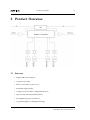
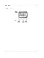
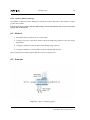
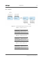
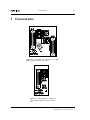
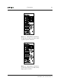
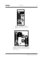
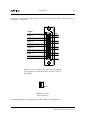
AES-VMUX/-SFP
User Manual
Revision: G
2014-07-10
Contents
1
Nevion Support
4
2
Revision History
5
3
Product Overview
6
3.1
6
4
5
6
Summary
Introduction
8
4.1
The Nevion SDTI audio concept
4.1.1
HW 1.1 enhancements
9
10
4.2
Top view
10
Specifications
11
5.1
Electrical SDTI
11
5.2
Optical SDTI
11
5.3
AES
11
5.4
Latencies
5.4.1
Slave modules
5.4.2
Clock master module
5.4.3
Audio latency
11
12
12
12
5.5
Power
12
5.6
Input wander and jitter tolerance
13
Configuration
14
6.1
Clock Master
6.1.1
SW2.6 Clock Master mode
14
15
6.2
Audio port direction
15
6.3
Port addresses
6.3.1
Input addresses
6.3.2
Output addresses
6.3.3
System address planning
16
17
17
18
6.4
Method
18
6.5
Examples
6.5.1
Example 1
6.5.2
Example 2
6.5.3
Example 3
18
19
21
22
6.6
SDTI input control
23
6.6.1
6.6.2
SW2.4 Manual/Auto
SW2.5 Optical/Electrical
23
23
6.7
DIP configuration mode
6.7.1
SW2.8 DIP config mode switch.
23
23
6.8
Multicon control
24
6.9
Status Monitoring
24
7
Connections
25
8
LEDs
29
9
8.1
Status LED
29
8.2
SDTI Input LED
29
8.3
EDH LED
29
8.4
Optical option LED
30
FLP4 commands
31
9.1
ablk
31
9.2
ceq
31
9.3
misc
31
9.4
mtx
32
9.5
pin and lsr
32
9.6
pwr
32
9.7
vmon
32
9.8
On-site re-programming.
33
10
General environmental requirements
34
11
Product Warranty
35
A
Materials declaration and recycling information
36
A.1
Materials declaration
36
A.2
Recycling information
37
Nevion Support
4
1 Nevion Support
Nevion Europe
Nevion USA
Nevion Europe
P.O. Box 1020 3204
Sandefjord, Norway
Nevion USA
1600 Emerson Avenue Oxnard,
CA 93033, USA
Support phone 1:
+47 33 48 99 97
Support phone 2: +47 90 60 99 99
Toll free North
America: (866) 515-0811
Outside North America: +1 (805) 247-8560
E-mail: [email protected]
See http://www.nevion.com/support/ for service hours for customer support globally.
AES-VMUX/-SFP User Manual Rev. G
Revision History
5
2 Revision History
Revision
Date
Comments
G
2014-06-24 Added example key figure and extra text on example figures. HW 1.1 features listed. Input
switch control added.
F
2013-11-15 Corrected AES-VMUX-C1 figure. Added cable length specification. Added AES-VMUX-SFP
E
2013-11-04 Added Materials decaration and support info
D
2013-06-02 TMLified
C
2013-03-11 First public release
B
2012-08-29 Manual configuration replaces autoconfiguration
A
2012-07-10 First revision
AES-VMUX/-SFP User Manual Rev. G
Product Overview
6
3 Product Overview
3.1 Summary
• Digital audio mass transport
• Asynchronous audio
• Phase correct audio clock recovery
• Predictable signal latency
• 16 AES ports per module, configurable direction
• Up to 64 AES channels per SDTI stream
• De-multiplexing from any timeslot.
• Loopable multiplex for distributed routing
AES-VMUX/-SFP User Manual Rev. G
Product Overview
7
• EDH for connection monitoring
• Optical SDTI options on SFP
AES-VMUX/-SFP User Manual Rev. G
Introduction
8
4 Introduction
The AES-VMUX is used to transport a large number of digital audio signals. The module is both
a multiplexer and demultiplexer and has 16 AES audio ports which may be used as inputs or
outputs. The module forms the core of a highly flexible audio transport and routing concept.
The audio transport has a fixed embedding and de-embedding delay of 64us. The audio signals
are transported completely asynchronously and bit transparently. The clock and phase information of each AES signal is transported along with the data and the signal is re-constructed at the
demultiplexer end. This keeps all of the AES signals time-aligned through the multiplex and preserves the signal phase alignment of multichannel audio.
The module encodes the audio into an SD SDTI video signal and uses the active video space in the
video frame. This allows routing and transport of the multiplex through an established broadcast
infrastructure and inspection with standard test equipment/ waveform viewers.
Modules may be daisy chained to increase the number of AES audio signals in the SDTI signal up
to a maximum of 64 AES channels.
Demultiplexing may be performed on any module from any of the audio signals in the SDTI multiplex. Each demultiplex channel is, in effect, a 64 to 1 AES router.
The module may also be equipped with an SFP providing optical link capability.
Six backplane types are presently available:• Double width backplanes
− AES-MUX-C1; All 16 AES ports on female d-sub DB25 and dual optical connectors.
− AES-VMUX-C5; As AES-MUX-C1 but with passive relay loop-through on electrical
SDTI.
• Single width backplanes
− AES-VMUX-C1; 8 AES ports on DB25, DIN 1.0/2.3 SDTI and dual optical connectors.
− AES-VMUX-C4; 8 AES ports on DB25, BNC SDTI and single optical connector.
• Flashcase single width backplanes
− AES-VMUX-C2; 16 AES ports on Molex Male KK, BNC SDTI output only and dual
optical connectors.
− AES-VMUX-C3; 16 AES ports on Molex Male KK, BNC SDTI and single optical connector.
SFPs are available for:• APD/CWDM Transceiver (18 wavelengths)
AES-VMUX/-SFP User Manual Rev. G
Introduction
9
• PIN/Standard laser tranceiver
The following Nevion video SFPs may be used but only one of the channels will be utilised.
• PIN dual receiver
• APD dual receiver
• Standard short haul dual laser
• CWDM dual laser
The optical input provides an extra input and the actual input may be chosen automatically or
set manually to the required input. In “Auto” mode, the input switches if a suitable signal is not
present, or if the signal disappears. There is no priority, the first input with a valid Nevion SDTI
audio signal is used.
4.1 The Nevion SDTI audio concept
The Nevion SDTI audio uses a normal 625 video frame and data format. This allows simple reuse
of existing legacy infrastructure and standard test and signal monitoring facilities.
The audio is embedded into the active video area on all video lines. An extra ancillary data packet
in the horizontal blanking area identifies the signal as a Flashlink SDTI audio multiplex.
The audio embedding uses two video lines to optimize the number of channels in the multiplex.
Seven stereo audio samples, embedded over two lines gives a maximum sample rate of 54.7 kHz.
This gives a high multiplexing efficiency of normal 48 kHz broadcast audio. The embedding pattern repeats over a two frame sequence. The phase reference is only inserted on one of the the two
lines and a frame counter is also embedded into the horizontal ancillary data packet.
The audio is embedded in fixed timeslots placed along the video line. The phase words are embedded in a block of video words placed first on every other line followed by seven audio blocks. Each
audio block has 64 audio timeslots. Each timeslot contains a 24 bit audio sample together with the
C, U and V bits from the AES subframe. The frame of AES audio is split between two audio blocks.
The audio multiplex appears on a video monitor as a series of vertical lines or stripes on a video
monitor. Dark green stripes are areas where no audio is embedded. Light green shows that the
channels are embedded but that the AES input is absent. An active audio channel appears as a
multicolored vertical stripe.
The SDI embedded clock is used as a clock reference and the audio is sampled with reference to
the start of the horizontal blanking. The phase measurement (similar to HD audio) is embedded
on the following line. All of the audio channels use the same reference point and all of the phase
measurements are embedded together in a block.
AES-VMUX/-SFP User Manual Rev. G
Introduction
10
4.1.1 HW 1.1 enhancements
Extra VCXO to allow input locking independant of output frequency. This gives the following:• Wider input jitter tolerance.
• Master mode module will de-multiplex audio to its AES outputs regardless of loop status.
i.e. System is more resiliant as a module may fail but the remaining chains of modules
still present will still work.
• More stable frequency of SDTI as the output frequency will not change until full lock
is achieved. i.e. Downstream modules will not lose lock when an upstream module is
removed. Performance with the relay backplane is now much improved.
• Wander tolerance of Master mode module is much larger allowing the use of a loop across
video links which are time multiplexed or packetized.
4.2 Top view
AES-VMUX/-SFP User Manual Rev. G
Specifications
11
5 Specifications
5.1 Electrical SDTI
Video standard
576/25i ITU-R BT.656
Error detection
EDH according to SMPTE RP165
Input cable length
Greater than 250m
All other SDI parameters conform to ITU-R BT.656
5.2 Optical SDTI
Optical range depends on the output power of the transmitter and the sensitivity of the receiver
of the next module.
See Nevion SFP datasheet available from support or the Nevion web site.
5.3 AES
AES3-2003
Inputs and outputs according to
Physical interface
110 ohm transformer balanced
Minimum sampling frequency
16.5 kHz
Maximum sampling frequency
54.7 kHz
Double sample rates using AES
Single channel double sampling frequency mode is supported. i.e. 96kHz Mono
signal using both sub-frames of the AES signal.
AES Outputs switch off completely if there is no signal in the routed timeslot.
5.4 Latencies
AES-VMUX/-SFP User Manual Rev. G
Specifications
12
5.4.1 Slave modules
HW
1.0
1.1
Video latency 0.56 us 0.85 us
5.4.2 Clock master module
The master module has a buffer which may be up to 2 video lines or 128 us. The actual latency
will depend on the latency due to the round trip which may be large if packetizing transports have
been used or if the stream has been received via satellite. The Clock master module will then add
as little latency as possible to round the total latency up to a multiple of two video lines. Minimum
latency is 128us.
5.4.3 Audio latency
Input to output via a single link
AES 128us / 6.145 audio samples @ 48kHz
Audio Latency will increase by the video latency every time the SDTI signal passes through a
module.
5.5 Power
All AES set to inputs
+5V
0.29 1.5W
All AES set to outputs
+5V
0.67A 3.4W
with SFP
+5V
add 1.0 W
AES-VMUX/-SFP User Manual Rev. G
Specifications
13
5.6 Input wander and jitter tolerance
Slave mode
Wander
locks to the input clock so wander is not relevant.
< 1 UI p-p.
Jitter
Master clock mode HW 1.0
Wander plus Jitter
< 1 UI p-p.
Master clock mode HW 1.1 Suitable for use with IP bridges etc.
Wander
512 UI p-p.
Jitter
< 1 UI p-p.
AES-VMUX/-SFP User Manual Rev. G
Configuration
14
6 Configuration
ON
ON
1
Figure 6.1
8
1
8
Module DIP switches.
The module DIP switches must be set up correctly. The module has 16 audio ports and the first
thing to consider is the port directions. This influences all of the following steps.
The three things that must set with the DIP switches are:
1. AES port direction
2. Input port embedding start address
+
Routing to the output ports may be controlled with Multicon GYDA if the ’DIP config mode’ is
off. If ’on’, the start address is set with the switches.
N1200_R1318
6.1 Clock
Master
This mode is only used by one card in the system and is only necessary when the SDTI signal is
sent in a loop. A module set as clock master will not try to lock to the input SDTI signal but will
still extract the data and re-multiplex the audio in the output streamHW 1.0 -as long as the jitter and wander in the signal is less than 1 UI.
HW 1.1 -in all cases to the AES outputs. The audio which is re-embedded into the multiplex will
AES-VMUX/-SFP User Manual Rev. G
+
3. Clock master mode
Configuration
15
contain errors, if the wander is very large or periodically when the loop is not complete. This hardware version may be used for looped configurations where one or more of the module connections
is over a link where wander is present on the output signal, i.e. IP or SDH video links.
6.1.1 SW2.6 Clock Master mode
• On: Module is the clock master
• Off: Module is a clock slave
6.2 Audio port direction
The 16 audio ports are controlled in blocks of four ports. There are only 5 valid combinations and
these are set with DIP switches SW2 1-3.
Table 6.1 AES Port direction DIP
switch settings
DIP SW2 1,2,3 Outputs Inputs
off,off,off
0
16
off,off,on
4
12
off,on ,off
8
8
off,on ,on
12
4
on ,on ,on
16
0
The AES outputs are always the first ports in the connectors.
e.g. 12 inputs and 4 outputs mode has AES 1-4 as outputs and AES 5-16 as inputs.
AES-VMUX/-SFP User Manual Rev. G
Configuration
16
6.3 Port addresses
AES-VMUX/-SFP User Manual Rev. G
Configuration
17
Table 6.2 Start address,
DIP switch settings
DIP SW1 1,2,3,4 or 5,6,7,8 Start address
off,off,off,off
1
off,off,off,on
5
off,off,on ,off
9
off,off,on ,on
13
off,on ,off,off
17
off,on ,off,on
21
off,on ,on ,off
25
off,on ,on ,on
29
on ,off,off,off
33
on ,off,off,on
37
on ,off,on ,off
41
on ,off,on ,on
45
on ,on ,off,off
49
on ,on ,off,on
53
on ,on ,on ,off
57
on ,on ,on ,on
61
6.3.1 Input addresses
The input address switches always set where the AES input signals are multiplexed.
The start timeslot used is set with DIP SW1 5-8 according the above table. The address start points
hop over 4 addresses because the AES ports are always inputs or outputs in blocks of four. The 16
combinations with 4 dip switches cover the range of addresses in the multiplex (16 timeslots x 4 =
64). The other input ports are placed consecutively in the multiplex after the start address.
The audio of these physical input ports will be available in the multiplex for all the AES-VMUX
cards in the chain, unless they are overwritten by inputs on other cards that have overlapping
multiplex addressing.
6.3.2 Output addresses
The AES output signal routing may be set by the DIP switches in DIP mode, or with the Multicon
GYDA system controller.
The signal routed to the first AES output port comes from the timeslot set with DIP SW1 1-4 if the
DIP config mode switch is on/up.
The other physical output ports have signals consecutively in the multiplex after this address.
The output port addressing may be individually controlled by the Multicon system controller if
the DIP config mode switch is off/down.
AES-VMUX/-SFP User Manual Rev. G
Configuration
18
6.3.3 System address planning
The number of timeslots in the multiplex used by the module depends on the number of input
ports in the module.
It is up to the user to ensure that the addressing is consistent and timeslots are not overwritten
(unless this is intended).
6.4 Method
1. First define the port directions on each module.
2. Arrange each site so that the modules with de-multiplexing channels come first in the
SDTI chain.
3. Assign the addresses to the modules with multiplexing channels.
4. Assign the addresses to the modules with de-multiplexing channels.
Most configurations will be simpler than the last two examples here.
6.5 Examples
Figure 6.2
Key to example graphics
AES-VMUX/-SFP User Manual Rev. G
Configuration
19
6.5.1 Example 1
Figure 6.3
32 channel AES transport from site A to site B.
Table 6.3 module 1, mux 1-16
SW2 1-3 off, off, off
Port Directions
Demux start address SW1 1-4 not used
Mux start address
Table 6.4
SW1 5-8 off, off, off, off
module 2, mux 17-32
SW2 1-3 off, off, off
Port Directions
Demux start address SW1 1-4 not used
Mux start address
Table 6.5
SW1 5-8 off, on, off, off
module 3, demux 1-16
Port Directions
SW2 1-3 on ,on ,on
Demux start address SW1 1-4 off, off, off, off
Mux start address
SW1 5-8 not used
AES-VMUX/-SFP User Manual Rev. G
Configuration
20
Table 6.6 module 4, demux 17-32
Port Directions
SW2 1-3 on ,on ,on
Demux start address SW1 1-4 off, on, off, off
Mux start address
SW1 5-8 not used
AES-VMUX/-SFP User Manual Rev. G
Configuration
21
6.5.2 Example 2
Figure 6.4
Point to point 8 out and 8 back.- 2 Modules, 2 sites.
Both modules are used for embedding and de-embedding and the SDTI signal is connected in a
loop so one of the modules must be the clock master.
Table 6.7
Port Directions
Local module
SW2 1-3 off, on, off
Master clock mode SW2.6
on
Demux start address SW1 1-4 off, off, on , off
Mux start address
Table 6.8
Port Directions
SW1 5-8 off, off, off, off
Remote module
SW2 1-3 off ,on ,off
Demux start address SW1 1-4 off, off, off, off
Mux start address
SW1 5-8 off, off, on , off
AES-VMUX/-SFP User Manual Rev. G
Configuration
22
6.5.3 Example 3
Figure 6.5 Point to point 16 out 16 back. 4 modules, 2 sites.
The two signal directions do not share any channels so keep the SDTI chains separate. The two
chains may then be configured identically.
Table 6.9 Modules
1 and 3, demux 1-16
Port Directions
SW2 1-3 on ,on ,on
Demux start address SW1 1-4 off, off, off, off
Mux start address
Table 6.10
SW1 5-8 not used
Modules 2 and 4, mux 1-16
Port Directions
SW2 1-3 off, off, off
Demux start address SW1 1-4 not used
Mux start address
SW1 5-8 off, off, off, off
AES-VMUX/-SFP User Manual Rev. G
Configuration
23
6.6 SDTI input control
If an optical is present on the module the input selector may be manually set to one of the inputs
or allowed to switch automatically.
If in DIP configuration mode:-
6.6.1 SW2.4 Manual/Auto
• On: Manual, input is fixed. SW2.5 setting is used
• Off: Auto, input will search for a Network SDTI audio signal. SW2.5 is ignored
6.6.2 SW2.5 Optical/Electrical
• On: Optical input is used
• Off: Electrical input is used
6.7 DIP configuration mode
The AES output port routing and the SDTI input switch control may be controlled by the system
controller and stored in the module. The AES input routing and the AES port directions parameters are always controlled with the DIP switches.
6.7.1 SW2.8 DIP config mode switch.
• On: The card will be configured with the DIP switches. The module will not accept commands from the system controller but may be monitored.
• Off: The module will be configured with the internally stored configuration and the AES
output routing and SDTI input may be controlled with FLP4 commands as listed in chapter 6.
As with all Flashlink modules, stored configurations in the Multicon controller will be applied to
a module that is plugged into a running system, provided that the switch SW2.8 is off and that the
last module present in the system was of the same type. A module with SW2.8 on, plugged into
a running system will overwrite the stored configuration in the Multicon controller with its own
configuration.
AES-VMUX/-SFP User Manual Rev. G
Configuration
24
6.8 Multicon control
The module may be monitored and controlled with the Multicon system controller. Port direction
and multiplexing time-slots may be monitored. Each de-multiplexer port / AES output is present
in the audio matrix which may be controlled by the system controller.
6.9 Status Monitoring
The AES digital audio signal presence for both multiplexer and de-multiplexer ports and the
on-board power levels are presented on the info page. Alarms are generated for AES signal loss,
SDTI loss, and power supply violations.
SFP presence and type are detected automatically and the optical input and output status will appear when appropriate.
Input switching control and position will only be displayed when the optical input is present.
Master clock mode is also only diplayed when active.
AES-VMUX/-SFP User Manual Rev. G
Connections
25
7 Connections
Figure 7.1 AES-MUX-C1: AES ports 1-16, BNC
SDTI and dual optical connectors
Figure 7.2 AES-VMUX-C1: AES ports
1-8, DIN SDTI and dual optical connectors
AES-VMUX/-SFP User Manual Rev. G
Connections
26
Figure 7.3 AES-VMUX-C2 :Flashcase,
16 AES Molex KK ports, BNC SDTI
o/p, dual optical connectors
Figure 7.4 AES-VMUX-C3 :Flashcase,
16 AES Molex KK ports, BNC SDTI,
single optical connector
AES-VMUX/-SFP User Manual Rev. G
Connections
27
Figure 7.5 AES-VMUX-C4: AES ports
1-8, BNC SDTI and single optical connector
Figure 7.6 AES-VMUX-C5: AES ports 1-16, BNC
SDTI with a passive loop-through relay and dual
optical connectors
AES-VMUX/-SFP User Manual Rev. G
Connections
28
The Passive loop backplane AES-VMUX-C5 may only be used with modules with hardware revisions HW 1.1 and greater.
AES 6
AES 7
AES 8
10 11 12 13
9
8
7
6
5
AES 5
4
AES 4
3
AES 3
2
AES 2
gnd
+
gnd
+
gnd
+
gnd
+
-
1
AES 1
14 15 16 17 18 19 20 21 22 23 24 25
Signal
gnd
gnd
+
gnd
+
gnd
+
gnd
+
Figure 7.7 The backplanes use the TASCAM standard
pin assignment for 8 balanced audio channels on the female DB-25.
+
gnd
Figure 7.8 Molex
KK connections
The standard backplane supplied with the AES-VMUX is the AES-MUX-C1.
AES-VMUX/-SFP User Manual Rev. G
LEDs
29
8 LEDs
The module has four LEDs.
8.1 Status LED
This turn red for 1 second when power is applied and then turn green when the FPGA code has
been loaded correctly.
The LED is green
• the module is programmed and functioning normally.
The LED is orange
• the module is not programmed or is in the process of being programmed
The LED is red
• there is something wrong with the module power supply levels OR
• the FPGA code has not loaded correctly
8.2 SDTI Input LED
The LED is green
• the SDTI signal is received correctly.
The LED is orange
• the input video standard is 625/25i but the signal is not a Nevion SDTI audio signal
The LED is red
• there is no input or the module is unable to lock to the signal.
8.3 EDH LED
The LED is green
• the SDTI signal is received correctly and has no errors in the EDH flags.
The LED is orange
AES-VMUX/-SFP User Manual Rev. G
LEDs
30
• the EDA flag is set meaning that an error has occurred in the multiplex in a module upstream.
The LED is red
• there is no input or the signal has errors.
8.4 Optical option LED
The LED is orange
• an optical SFP option is not present OR
• the SFP is not a Nevion video SFP.
The LED is red:
• the input signal is too low or high power OR
• the laser has failed
The LED is green:
• the optical input signal is present and correct AND
• the laser is operating with the correct power
AES-VMUX/-SFP User Manual Rev. G
FLP4 commands
31
9 FLP4 commands
FLP stands for Flashlink Protocol. The current revision of this protocol is 4, hence FLP4. This
specification is available from Nevion support.
The following FLP4 block commands are used in the monitoring and control of the module.
• ablk
• ceq
• lsr
• misc
• mtx
• pin
• pwr
• vmon
FLP4 block numbering is 0 based while the display on the webpage and numbering of the physical
connections is 1 based.
9.1 ablk
The ablk blocks list the AES port direction and signal sampling frequency.
Inputs report AES input signal presence.
Outputs report signal presence on the routed timeslot.
9.2 ceq
The cable equaliser block reports signal presence on the electrical input.
9.3 misc
The misc block has several keywords reporting the following:• the programming state of the module where ’fin’ indicates a successful programming.
• ovr is the Card Mode where configuratiuon is not allowed form GYDA.
• the locating state where the front LEDs flash. The keyword ’locating’ is followed by the
number of seconds of locating state remaining.
AES-VMUX/-SFP User Manual Rev. G
FLP4 commands
32
9.4 mtx
The two first matrices change sizes to suit the AES port directions but both have 64 sources.
• mtx 0 is de-multiplex source control.
• mtx 16 is multiplex timeslot control.
• mtx 32 is used to report the SDTI input in use. 0 is the electrical input, 1 is the optical
input.
• mtx 33 is used to indicate that the Master clock mode is active.
• mtx 34 is used to set the SDTI input selector mode. 0 is Auto, 1 is fixed to electrical, 2 is
fixed to optical.
9.5 pin and lsr
The optical option parameters and status are read from the installed Nevion video SFPs
9.6 pwr
The pwr blocks from 0 to 2 list the levels of the power supplies as measured by the micro-controller.
• 0 is digital 1.2V
• 1 is the frame 5V
• 2 is digital 3.3V
The frame supply is measured after the module fuse and filtering.
9.7 vmon
The vmon block is a video stream analyser block which can identify a number of different errors
in the video frame. The info page shows the errors that occurred since the last GYDA update with
red.
Errors that will be present as a result of other errors are masked out to allow the user focus to see
the most important error. i.e. If the lock error is active (red), the other errors will be green.
The block has an error counter with accumulates the number of video frames that have had errors.
The counter may be reset on the info page.
The different errors may be masked out individually by the user in order to isolate certain events.
The vmon block is configured on the conf page but the error mask is only shown after the black
’pulldown’ triangle has been clicked on. The masking effects the counter as the vmon block no
longer sees the error. Masked out errors are shown as grey blocks on the info page.
The signal integrity alarm will be triggered if the error parameters shown on the conf page are
AES-VMUX/-SFP User Manual Rev. G
FLP4 commands
33
exceeded.
The VS (Video Standard) alarm is triggered if the input video signal is not a Nevion SDTI audio
signal
9.8 On-site re-programming.
The module may be re-programmed on site with a GYDA Multicon system controller. Firmware
and instructions will be provided by Nevion support when necessary.
AES-VMUX/-SFP User Manual Rev. G
General environmental requirements
34
10 General environmental requirements
The equipment will meet the guaranteed performance specification under the following environmental conditions:
Operating room temperature range
0°C to 45°C
Operating relative humidity range <90% (non-condensing)
The equipment will operate without damage under the following environmental conditions:
Temperature range
10°C to 55°C
Relative humidity range <90% (non-condensing)
AES-VMUX/-SFP User Manual Rev. G
35
11 Product Warranty
The warranty terms and conditions for the product(s) covered by this manual follow the General
Sales Conditions by Nevion, which are available on the company web site:
http://www.nevion.com
AES-VMUX/-SFP User Manual Rev. G
Materials declaration and recycling information
36
Appendix A Materials declaration and recycling information
A.1 Materials declaration
For product sold into China after 1st March 2007, we comply with the “Administrative Measure
on the Control of Pollution by Electronic Information Products”. In the first stage of this legislation, content of six hazardous materials has to be declared. The table below shows the required
information.
This is indicated by the product marking:
AES-VMUX/-SFP User Manual Rev. G
37
A.2 Recycling information
Nevion provides assistance to customers and recyclers through our web site:
http://www.nevion.com/. Please contact Nevion’s Customer Support for assistance with recycling if this site does not show the information you require.
Where it is not possible to return the product to Nevion or its agents for recycling, the following
general information may be of assistance:
Before attempting disassembly, ensure the product is completely disconnected from power and
signal connections.
All major parts are marked or labeled to show their material content.
Depending on the date of manufacture, this product may contain lead in solder.
Some circuit boards may contain battery-backed memory devices.
AES-VMUX/-SFP User Manual Rev. G