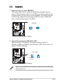
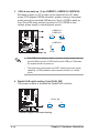
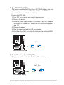
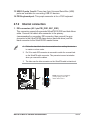
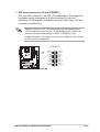
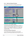
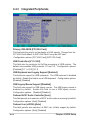
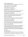
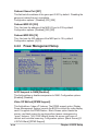
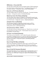
1
User Guide
Motherboard
A7N8X-E
Deluxe
E1876
Checklist
Revised Edition V3
January 2005
Copyright © 2005 ASUSTeK COMPUTER INC. All Rights Reserved.
No part of this manual, including the products and software described in it, may be
reproduced, transmitted, transcribed, stored in a retrieval system, or translated into any
language in any form or by any means, except documentation kept by the purchaser for
backup purposes, without the express written permission of ASUSTeK COMPUTER INC.
(“ASUS”).
Product warranty or service will not be extended if: (1) the product is repaired, modified or
altered, unless such repair, modification of alteration is authorized in writing by ASUS; or (2)
the serial number of the product is defaced or missing.
ASUS PROVIDES THIS MANUAL “AS IS” WITHOUT WARRANTY OF ANY KIND, EITHER
EXPRESS OR IMPLIED, INCLUDING BUT NOT LIMITED TO THE IMPLIED WARRANTIES
OR CONDITIONS OF MERCHANTABILITY OR FITNESS FOR A PARTICULAR PURPOSE.
IN NO EVENT SHALL ASUS, ITS DIRECTORS, OFFICERS, EMPLOYEES OR AGENTS BE
LIABLE FOR ANY INDIRECT, SPECIAL, INCIDENTAL, OR CONSEQUENTIAL DAMAGES
(INCLUDING DAMAGES FOR LOSS OF PROFITS, LOSS OF BUSINESS, LOSS OF USE
OR DATA, INTERRUPTION OF BUSINESS AND THE LIKE), EVEN IF ASUS HAS BEEN
ADVISED OF THE POSSIBILITY OF SUCH DAMAGES ARISING FROM ANY DEFECT OR
ERROR IN THIS MANUAL OR PRODUCT.
SPECIFICATIONS AND INFORMATION CONTAINED IN THIS MANUAL ARE FURNISHED
FOR INFORMATIONAL USE ONLY, AND ARE SUBJECT TO CHANGE AT ANY TIME
WITHOUT NOTICE, AND SHOULD NOT BE CONSTRUED AS A COMMITMENT BY ASUS.
ASUS ASSUMES NO RESPONSIBILITY OR LIABILITY FOR ANY ERRORS OR
INACCURACIES THAT MAY APPEAR IN THIS MANUAL, INCLUDING THE PRODUCTS
AND SOFTWARE DESCRIBED IN IT.
Products and corporate names appearing in this manual may or may not be registered
trademarks or copyrights of their respective companies, and are used only for identification or
explanation and to the owners’ benefit, without intent to infringe.
ii
Contents
Features
Notices ........................................................................................... vi
Safety information ......................................................................... vii
About this guide ............................................................................ viii
How this guide is organized ................................................ viii
Conventions used in this guide ............................................. ix
Where to find more information ............................................. ix
A7N8X-E Deluxe specifications summary ....................................... x
Chapter 1: Product introduction
1.1
1.2
1.3
Welcome! ........................................................................... 1-1
Package contents ............................................................... 1-1
Special features .................................................................. 1-2
1.3.1 Product Highlights .................................................. 1-2
1.3.2 Unique ASUS features ........................................... 1-3
Chapter 2: Hardware information
2.1
2.2
2.3
2.4
2.5
Before you proceed ............................................................ 2-1
Motherboard overview ........................................................ 2-2
2.2.1 Placement direction ............................................... 2-2
2.2.2 Screw holes ........................................................... 2-2
2.2.3 Motherboard layout ................................................ 2-3
2.2.4 Layout Contents ..................................................... 2-4
Central Processing Unit (CPU) ........................................... 2-6
2.3.1 Overview ................................................................ 2-6
2.3.2 Installing the CPU .................................................. 2-6
System memory ................................................................. 2-8
2.4.1 Overview ................................................................ 2-8
2.4.2 Memory configurations .......................................... 2-8
2.4.3 Installing a DIMM ................................................. 2-10
2.4.4 Removing a DIMM ............................................... 2-10
Expansion slots ................................................................. 2-11
2.5.1 Installing an expansion card .................................2-11
2.5.2 Configuring an expansion card ............................. 2-11
2.5.3 Interrupt assignments .......................................... 2-12
2.5.4 PCI slots .............................................................. 2-13
2.5.5 AGP slot ............................................................... 2-13
2.5.6 Wi-Fi slot .............................................................. 2-14
iii
Contents
Safeguards
2.6
2.7
Jumpers ............................................................................ 2-15
Connectors ....................................................................... 2-18
2.7.1 Rear panel connectors ......................................... 2-18
2.7.2 Internal connectors .............................................. 2-19
Chapter 3: Powering up
3.1
3.2
3.3
Starting up for the first time ................................................ 3-1
Powering off the computer ................................................. 3-2
3.2.1 Using the OS shut down function .......................... 3-2
3.2.2 Using the dual function power switch .................... 3-2
ASUS POST Reporter™ .................................................... 3-3
3.3.1 Vocal POST messages .......................................... 3-3
3.3.2 Winbond Voice Editor ............................................ 3-5
Chapter 4: BIOS setup
4.1
4.2
4.3
4.4
iv
Managing and updating your BIOS .................................... 4-1
4.1.1 Creating a bootable floppy disk ............................. 4-1
4.1.2 AwardBIOS Flash Utility ......................................... 4-2
4.1.3 ASUS Update ........................................................ 4-5
BIOS Setup program .......................................................... 4-7
4.2.1 BIOS menu screen ................................................ 4-8
4.2.2 Menu bar ................................................................ 4-8
4.2.3 Navigation keys ..................................................... 4-8
4.2.4 Menu items ............................................................ 4-9
4.2.5 Sub-menu items ..................................................... 4-9
4.2.6 Configuration fields ................................................ 4-9
4.2.7 General help .......................................................... 4-9
4.2.8 Pop-up window ...................................................... 4-9
4.2.9 Scroll bar ................................................................ 4-9
Main menu ........................................................................ 4-10
4.3.1 System Time [xx:xx:xxxx] ..................................... 4-10
4.3.2 System Date [Day xx/xx/xxxx] ............................. 4-10
4.3.3 Legacy Diskette A [1.44M, 3.5 in.] ....................... 4-10
4.3.4 Halt On [All Errors] ............................................... 4-10
4.3.5 Primary and Secondary Master/Slave .................. 4-11
Advanced menu ............................................................... 4-14
4.4.1 Advanced BIOS Features .................................... 4-15
4.4.2 Advanced Chipset Features ................................ 4-18
4.4.3 Integrated Peripherals ......................................... 4-22
Contents
4.5
4.6
4.7
4.4.4 Power Management Setup .................................. 4-24
4.4.5 PnP/PCI Configurations ....................................... 4-26
Security Menu .................................................................. 4-27
Hardware Monitor Menu ................................................... 4-29
Exit Menu ......................................................................... 4-30
Chapter 5: Software support
5.1
5.2
5.3
5.4
5.5
5.6
5.7
Install an operating system ................................................. 5-1
Support CD information ...................................................... 5-1
5.2.1 Running the support CD ........................................ 5-1
5.2.2 Drivers menu ......................................................... 5-2
5.2.3 Utilities menu ......................................................... 5-3
5.2.4 ASUS Contact Information ..................................... 5-4
5.2.5 Other information ................................................... 5-5
NVIDIA® nForce control panel ............................................ 5-7
5.3.1 Launching the NVIDIA® control panel .................... 5-7
5.3.2 Main ....................................................................... 5-7
5.3.3 Speaker Setup ....................................................... 5-7
5.3.4 MIDI ....................................................................... 5-9
5.3.5 Environment ........................................................... 5-9
5.3.6 Applications ........................................................... 5-9
5.3.7 Information ........................................................... 5-10
NVIDIA® NVSwap 1.0 Utility ..............................................5-11
RAID 0/RAID 1 Configurations ......................................... 5-13
5.5.1 Install the hard disks ............................................ 5-13
5.5.2 Creating and deleting RAID sets ......................... 5-14
Onboard Marvell Gigabit LAN drivers for ................................
Windows 98SE/ME ........................................................... 5-16
Marvell® Virtual Cable Tester™ (VCT) Technology ........... 5-17
Quick Reference Card
v
Notices
Federal Communications Commission Statement
This device complies with Part 15 of the FCC Rules. Operation is subject to
the following two conditions:
• This device may not cause harmful interference, and
• This device must accept any interference received including interference
that may cause undesired operation.
This equipment has been tested and found to comply with the limits for a
Class B digital device, pursuant to Part 15 of the FCC Rules. These limits
are designed to provide reasonable protection against harmful interference
in a residential installation. This equipment generates, uses and can radiate
radio frequency energy and, if not installed and used in accordance with
manufacturer’s instructions, may cause harmful interference to radio
communications. However, there is no guarantee that interference will not
occur in a particular installation. If this equipment does cause harmful
interference to radio or television reception, which can be determined by
turning the equipment off and on, the user is encouraged to try to correct the
interference by one or more of the following measures:
• Reorient or relocate the receiving antenna.
• Increase the separation between the equipment and receiver.
• Connect the equipment to an outlet on a circuit different from that to
which the receiver is connected.
• Consult the dealer or an experienced radio/TV technician for help.
The use of shielded cables for connection of the monitor to the
graphics card is required to assure compliance with FCC regulations.
Changes or modifications to this unit not expressly approved by the
party responsible for compliance could void the user’s authority to
operate this equipment.
Canadian Department of Communications Statement
This digital apparatus does not exceed the Class B limits for radio noise
emissions from digital apparatus set out in the Radio Interference
Regulations of the Canadian Department of Communications.
This class B digital apparatus complies with Canadian ICES-003.
vi
Safety information
Electrical safety
• To prevent electrical shock hazard, disconnect the power cable from
the electrical outlet before relocating the system.
• When adding or removing devices to or from the system, ensure that
the power cables for the devices are unplugged before the signal
cables are connected. If possible, disconnect all power cables from the
existing system before you add a device.
• Before connecting or removing signal cables from the motherboard,
ensure that all power cables are unplugged.
• Seek professional assistance before using an adpater or extension
cord. These devices could interrupt the grounding circuit.
• Make sure that your power supply is set to the correct voltage in your
area. If you are not sure about the voltage of the electrical outlet you
are using, contact your local power company.
• If the power supply is broken, do not try to fix it by yourself. Contact a
qualified service technician or your retailer.
Operation safety
• Before installing the motherboard and adding devices on it, carefully
read all the manuals that came with the package.
• Before using the product, make sure all cables are correctly connected
and the power cables are not damaged. If you detect any damage,
contact your dealer immediately.
• To avoid short circuits, keep paper clips, screws, and staples away from
connectors, slots, sockets and circuitry.
• Avoid dust, humidity, and temperature extremes. Do not place the
product in any area where it may become wet.
• Place the product on a stable surface.
• If you encounter technical problems with the product, contact a
qualified service technician or your retailer.
vii
About this guide
This user guide contains the information you need when installing and
configuring the motherboard.
How this guide is organized
This manual contains the following parts:
• Chapter 1: Product introduction
This chapter describes the motherboard features of the and the new
technologies it supports.
• Chapter 2: Hardware information
This chapter lists the hardware setup procedures that you have to
perform when installing system components. It includes description of
the jumpers and connectors on the motherboard.
• Chapter 3: Powering up
This chapter describes the power up sequence, the vocal POST
messages, and ways of shutting down the system.
• Chapter 4: BIOS setup
This chapter tells how to change system settings through the BIOS
Setup menus. Detailed descriptions of the BIOS parameters are also
provided.
• Chapter 5: Software support
This chapter describes the contents of the support CD that comes with
the motherboard package.
viii
Conventions used in this guide
To make sure that you perform certain tasks properly, take note of the
following symbols used throughout this manual.
DANGER/WARNING: Information to prevent injury to yourself
when trying to complete a task.
CAUTION: Information to prevent damage to the components
when trying to complete a task.
IMPORTANT: Information that you MUST follow to complete a
task.
NOTE: Tips and additional information to aid in completing a task.
Where to find more information
Refer to the following sources for additional information and for product
and software updates.
1. ASUS websites
The ASUS websites worldwide provide updated information on ASUS
hardware and software products. Refer to the ASUS contact
information.
2. Optional documentation
Your product package may include optional documentation, such as
warranty flyers, that may have been added by your dealer. These
documents are not part of the standard package.
ix
A7N8X-E Deluxe specifications summary
CPU
Socket A for AMD Duron™/AMD Athlon™/AMD Athlon™ XP
3200+ processors
Front Side Bus (FSB)
400/333/266/200Mhz
Chipset
Northbridge: NVIDIA® nForce2 Ultra 400
Southbridge: NVIDIA® nForce2 MCP-T
Memory
Dual-channel memory architecture
3 x 184-pin DDR DIMM sockets for up to 3GB memory
Supports PC3200/PC2700/PC2100/PC1600 unbuffered
non-ECC DDR DIMMs
Expansion slots
5 x PCI
1 x AGP Pro/8X (1.5V only)
1 x ASUS proprietary Wi-Fi slot
Storage
2 x UltraDMA 133/100/66/33
2 x Serial ATA with RAID 0, 1 support
Audio
MCP-T southbridge integrated Audio Processor Unit (APU) +
Realtek ALC650 6-channel audio CODEC
LAN
Marvell® 88E8001 Gigabit LAN
MCP-T southbridge integrated controller MAC + Realtek
8201BL LAN PHY
1394
MCP-T southbridge integrated IEEE1394a controller +
Realtek 8801B PHY
Special Features
ASUS Q-Fan Technology
ASUS POST Reporter
ASUS C.O.P. (CPU Overheating Protection)
Power Loss Restart
CPU Throttle
Rear Panel I/O
1 x parallel port
1 x serial port
1 x PS/2 keyboard port
1 x PS/2 mouse port
1 x S/PDIF in/out port
1 x surround L/R audio jack
1 x CNTR/LFE audio jack
1 x audio I/O port
1 x Gigabit RJ-45 Port
1 x Fast Ethernet RJ-45 port
4 x USB 2.0 ports
(continued on the next page)
x
A7N8X-E Deluxe specifications summary
Internal I/O
Connectors
USB 2.0 connector supports additional 2 USB 2.0 ports
Game/MIDI connector
CPU/Power/Chassis fan connectors
2 x IDE connectors
20-pin ATX power connector
2 x SATA connectors
2 x 1394 connectors
Chassis intrusion connector
Infrared module connector
CD / AUX / Modem connector
Front panel audio connector
Serial port 2 connector
S/PDIF connector
BIOS features
4Mb Flash ROM, Award BIOS, PnP, DMI2.0, Green
Industry standard
PCI 2.2, USB 1.1/2.0.
Manageability
DMI 2.0, WOL, WOR, Chassis Intrusion
Form Factor
ATX form factor: 12 in x 9.6 in (30.5 cm x 24.5 cm)
Support CD contents
Device drivers
ASUS PC Probe
Anti-virus utility
ASUS LiveUpdate Utility
* Specifications are subject to change without notice.
xi
xii
Chapter 1
This chapter describes the motherboard
features and the new technologies it
supports.
Product introduction
Chapter summary
1.1
Welcome! ........................................................ 1-1
1.2
Package contents .......................................... 1-1
1.3
Special features ............................................. 1-2
ASUS A7N8X-E Deluxe motherboard
1.1
Welcome!
Thank you for buying the ASUS® A7N8X-E Deluxe motherboard!
The motherboard delivers a host of new features and latest technologies
making it another standout in the long line of ASUS quality motherboards!
The motherboard supports the AMD Athlon™, AMD Athlon™ XP or AMD
Duron™ processors in a Socket A (462-pin) package with the NVIDIA®
nForce2™ Ultra 400 chipset to set a new benchmark for an effective
desktop platform solution.
Supporting up to 3GB of system memory with PC3200/PC2700/PC2100/
PC1600 DDR SDRAM, high-resolution graphics via an AGP 8X slot, SATA,
RAID, IEEE 1394, USB 2.0, and 6-channel audio features, the
motherboard takes you ahead in the world of power computing!
Before you start installing the motherboard, and hardware devices on it,
check the items in your package with the list below.
1.2
Package contents
Check your motherboard package for the following items.
ASUS motherboard
ASUS support CD
2 x SATA cables
1 x SATA power cable
1 x 2-port USB module w/ cable
1 x 2-port IEEE1394 module
1 x 80-conductor ribbon cable for UltraDMA/66/100/133 IDE drives
1 x 40-conductor IDE cable
1 x Ribbon cable for a 3.5-inch floppy drive
WinDVD Suite
I/O shield
Bag of extra jumper caps
User Guide (includes Quick Reference Card)
Quick Setup Guide
Jumper/Connector sticker
If any of the above items is damaged or missing, contact your retailer.
ASUS A7N8X-E Deluxe motherboard
1-1
1.3
Special features
1.3.1 Product Highlights
Latest processor technology
The motherboard supports the latest AMD Athlon™, Athlon™ XP and AMD
Duron™ processors via a 462-pin surface mount ZIF socket. The AMD
Athlon™ and AMD Athlon™ XP processors features a 400Mhz front side
bus and the QuantiSpeed™ architecture for rapid execution of
applications.
NVIDIA® nForce™ Platform Processing Architecture
The motherboard combines the power of NVIDIA’s nForce2™ Ultra 400
and nForce2™ MCP-T chipsets that improves processing efficiency and
overall system performance.
Serial ATA solution
The motherboard supports two interfaces compliant to the Serial ATA
(SATA) specification, an evolutionary replacement of the Parallel ATA
storage interface. The Serial ATA specification allows for thinner, more
flexible cables with lower pin count, reduced voltage requirement, up to
150 MB/s data transfer rate. See page 2-21.
AGP 8X support
The motherboard support AGP 8X (AGP 3.0) specification offering 2.12
GB/s bandwidth. See page 2-13.
Dual LAN (Fast-Ethernet and Gigabit) solution
The onboard Marvell® Gigabit LAN controller and Fast-Ethernet LAN
controller integrated in the southbridge supply two separate ports for LAN
on Motherboard (LOM) applications. The Marvell® Gigabit LAN controller is
equipped with the net-diagnosing utility, VCT (Virtual Cable Tester), that
intelligently diagnoses and reports cable faults from a remote location up
to 100 meters. This feature helps maintain a more stable network
connection. See pages 2-18, 5-17.
S/PDIF in/out function
The motherboard’s S/PDIF out function turns your computer into a highend entertainment system with digital connectivity.
1-2
Chapter 1: Product introduction
IEEE 1394 support
The IEEE 1394 interface provides high-speed and flexible PC connectivity
to a wide range of peripherals and devices compliant to IEEE 1394a
standards. The IEEE 1394 interface allows up to 400Mbps transfer rates
through simple, low-cost, high-bandwidth asynchronous (real-time) data
interfacing between computers, peripherals, and consumer electronic
devices such as camcorders, VCRs, printers,TVs, and digital cameras.
See page 2-25.
6-channel digital audio
The Realtek ALC650 AC’97 audio 6-channel CODEC works with the Audio
Processing Unit (APU) integrated in the NVIDIA® NForce2™ MCP-T
southbridge to provide 3D surround audio effects and Dolby® Digital
cinematic-quality audio.
6 USB 2.0 ports
The motherboard implements the Universal Serial Bus (USB) 2.0
specification to provide up to 480Mbps connection speed. See page 2-24.
1.3.2 Unique ASUS features
ASUS Wi-Fi slot
The ASUS Wi-Fi slot is based on the 802.11b/g wireless standard that is
specifically designed for the ASUS WiFi-b™ add-on card to set up a
wireless LAN environment. The ASUS WiFi-b™ add-on card bundles the
Software AP (Access Point) to save the extra cost of a stand-alone AP.
The card comes with user-friendly utilities and applications that allow quick
connection to notebooks, PDAs, and other wireless LAN peripherals. See
page 2-14.
ASUS Q-Fan technology
The ASUS Q-Fan technology smartly adjusts the fan speeds according to
the system loading to ensure quiet, cool, and efficient operation. See
pages 4-29.
ASUS A7N8X-E Deluxe motherboard
1-3
ASUS POST Reporter™
The motherboard offers a new exciting feature called the ASUS POST
Reporter™ to provide friendly voice messages and alerts during the
Power-On Self-Tests (POST). Through an added external speaker, you will
hear the messages informing you of the system boot status and causes of
boot errors, if any. The bundled Winbond Voice Editor software allows you
to customize the voice messages, and provides multi-language support.
See page 3-3.
1-4
Chapter 1: Product introduction
Chapter 2
This chapter lists the hardware setup
procedures that you have to perform when
installing system components. It includes
description of the jumpers and connectors
on the motherboard.
Hardware information
Chapter summary
2.1
Before you proceed ....................................... 2-1
2.2
Motherboard overview ................................... 2-2
2.3
Central Processing Unit (CPU) ..................... 2-6
2.4
System memory ............................................. 2-8
2.5
Expansion slots ............................................ 2-11
2.6
Jumpers ........................................................ 2-15
2.7
Connectors ................................................... 2-18
ASUS A7N8X-E Deluxe motherboard
2.1
Before you proceed
Take note of the following precautions before you install motherboard
components or change any motherboard settings.
1. Unplug the power cord from the wall socket before touching any
component.
2. Use a grounded wrist strap or touch a safely grounded object or to
a metal object, such as the power supply case, before handling
components to avoid damaging them due to static electricity.
3. Hold components by the edges to avoid touching the ICs on them.
4. Whenever you uninstall any component, place it on a grounded
antistatic pad or in the bag that came with the component.
5. Before you install or remove any component, ensure that the
ATX power supply is switched off or the power cord is
detached from the power supply. Failure to do so may cause
severe damage to the motherboard, peripherals, and/or
components.
Onboard LED
The motherboard comes with a standby power LED. When lit, the green
LED indicates that the system is ON, in sleep mode, or in soft-off mode, a
reminder that you should shut down the system and unplug the power
cable before removing or plugging in any motherboard component. The
illustration below shows the location of the onboard LED.
PWR_LED1
A7N8X-E
®
A7N8X-E Onboard LED
ON
Standby
Power
ASUS A7N8X-E Deluxe motherboard
OFF
Powered
Off
2-1
2.2
Motherboard overview
Before you install the motherboard, study the configuration of your chassis
to ensure that the motherboard fits into it.
Make sure to unplug the power cord before installing or removing the
motherboard. Failure to do so may cause you physical injury and
damage motherboard components.
2.2.1 Placement direction
When installing the motherboard, make sure that you place it into the
chassis in the correct orientation. The edge with external ports goes to the
rear part of the chassis as indicated in the image below.
2.2.2 Screw holes
Place nine (9) screws into the holes indicated by circles to secure the
motherboard to the chassis.
Do not overtighten the screws! Doing so may damage the
motherboard.
Place this side towards
the rear of the chassis
2-2
Chapter 2: Hardware information
2.2.3 Motherboard layout
24.5cm (9.6in)
PS/2
T: Mouse
B: Keyboard
KBPWR1
Bottom:
USBPW12
CPU_FAN1
Socket 462
Top:
Top:
CPU_FSB
Top:Line In
Center:Line Out
Below:Mic In
2 3
4 5
SEC_IDE1
Realtek
RTL8201
PWR_FAN1 CHA_FAN1
FLOPPY1
0 1
30.5cm (12.0in)
Bottom:
USB1 RJ-45
USB2
nForce2
SPP
Ultra400
Chipset
PRI_IDE1
NVIDIA
SPDIFOUT2
ATX Power Connector
USBPW34
DDR DIMM_B1 (64/72 bit, 184-pin module)
SURR1
DDR DIMM_A1 (64/72 bit, 184-pin module)
CNTR/
LFE1
PARALLEL PORT
COM1
DDR DIMM_A2 (64/72 bit, 184-pin module)
USB3 RJ-45
USB4
Accelerated Graphics Port (AGP Pro)
PCI 1
NVIDIA
nForce2
MCP-T
Chipset
A7N8X-E
IE1394_2
Super
I/O
Marrell
88E8001
PCI LAN
4Mb
BIOS
PCI 2
IE1394_1
®
SPDIF1
GLAN_SW
PCI 3
CLRTC1
CR2032 3V
Lithium Cell
CMOS Power
Realtek
RTL8801
COM2
USB56
SATA_EN1
PCI 4
CD1
GAME1
SATALInk
Chipset
SB_PWR1
FPAUDIO1
AUX1
Audio
Codec
PCI 5
ASUS
ASIC
with Hardware
Monitor
Speech
Controller
MODEM1
WIFI
ASUS A7N8X-E Deluxe motherboard
USBPW56
IR_CON1
CHASSIS1
SATA_RAID2 SATA_RAID1
CTRL_PANEL1
2-3
2.2.4 Layout Contents
Slots
1. PCI slots
p. 2-13
2. AGP slot
p. 2-13
3. Wi-Fi slot
p. 2-14
4. DDR DIMM slots
p. 2-8
Jumpers
1. Keyboard wake-up (3-pin KBPWR1)
p. 2-15
2. Central Processing Unit FSB Setting (3-pin CPU_FSB)
p. 2-15
3. USB device wake-up (3-pin USBPW12, USBPW34, USBPW56) p. 2-16
4. Gigabit LAN Setting (3-pin GLAN_SW)
p. 2-16
5. Clear RTC RAM (3-pin CLRTC1)
p. 2-17
6. Serial ATA setting (3-pin SATA_EN1)
p. 2-17
Rear Panel Connectors
2-4
1. PS/2 mouse port
p. 2-18
2. Fast Ethernet port (RJ-45)
p. 2-18
3. Parallel port
p. 2-18
4. Gigabit LAN port (RJ-45)
p. 2-18
5. Line In jack
p. 2-18
6. Line Out jack
p. 2-18
7. Microphone jack
p. 2-18
8. USB 2.0 ports 1 and 2
p. 2-18
9. S/PDIF out jack
p. 2-18
10. Surround L/R audio jack
p. 2-18
11. Center/LFE audio jack
p. 2-18
12. Serial connector
p. 2-18
13. USB 2.0 ports 3 and 4
p. 2-19
14. PS/2 keyboard port
p. 2-19
Chapter 2: Hardware information
Internal Connectors
1. Primary IDE connector (40-1 pin PRI_IDE)
p. 2-19
2. Secondary IDE connector (40-1 pin SEC_IDE)
p. 2-19
3. Floppy disk connector (34-1 pin FLOPPY1)
p. 2-20
4. Chassis intrusion connector (4-1 pin CHASSIS1)
p. 2-20
5. Serial ATA connectors (7-pin SATA_RAID1, SATA_RAID2 )
p. 2-21
6. CPU fan connector (3-pin CPU_FAN1)
p. 2-22
7. Power fan connector (3-pin PWR_FAN1)
p. 2-22
8. Chassis fan connector (3-pin CHA_FAN1)
p. 2-22
9. Serial Port 2 connector (10-1 pin COM2)
p. 2-22
10. ATX power connector (20-pin ATXPWR1)
p. 2-23
11. USB headers (10-1 pin USB56)
p. 2-24
12. MODEM connector (4-pin MODEM1)
p. 2-25
13. CD connector (4-pin CD1)
p. 2-25
14. AUX connector (4-pin AUX1)
p. 2-25
15. IEEE 1394 connectors (10-1 pin IE1394_1, IE1394_2)
p. 2-25
16. Front panel audio connector (10-1 pin FP_AUDIO)
p. 2-26
17. Digital audio connector (6-1 pin SPDIF1)
p. 2-26
18. GAME/MIDI connector (16-1 pin GAME1)
p. 2-27
19. Infrared module connector (10-1 pin IR_CON1)
p. 2-27
20. System panel connector (20-pin CTRL_PANEL1)
p. 2-28
- System Power LED Lead (Green 3-1 pin PLED)
- Keyboard Lock Lead (Brown 2-pin KEYLOCK)
- System Warning Speaker Lead (Orange 4-pin SPKR)
- Reset Switch (Blue 2-pin RESET)
- ATX Power Switch (Yellow 2-pin PWRBTN)
- Hard Disk Activity LED (Red 2-pin IDE_LED)
ASUS A7N8X-E Deluxe motherboard
2-5
2.3
Central Processing Unit (CPU)
2.3.1 Overview
The motherboard comes with a surface mount 462-pin Zero Insertion
Force (ZIF) socket designed for the AMD Athlon™, AMD Athlon™ XP and
AMD Duron™ processors.
Take note of the marked corner (with
gold triangle) on the CPU. This mark
should match a specific corner on the
socket to ensure correct installation.
Gold triangle
Do not use processors with core speeds of less than 1GHz on this
motherboard.
2.3.2 Installing the CPU
Follow these steps to install a CPU.
1. Locate the 462-pin ZIF socket on the motherboard.
2-6
Chapter 2: Hardware information
2. Unlock the socket by pressing the
lever sideways, then lift it up to a
90°-100° angle.
90°-100° angle
Socket lever
Make sure that the socket lever is lifted up to 90°-100° angle,
otherwise the CPU does not fit in completely.
3. Position the CPU above the
socket such that the CPU corner
with the gold triangle matches the
base of the socket lever.
4. Carefully insert the CPU into the
socket until it fits in place.
Gold triangle
The CPU fits only in one correct orientation. DO NOT force the CPU
into the socket to prevent bending the pins and damaging the CPU!
5. When the CPU is in place, push
down the socket lever to secure
the CPU. The lever clicks on the
side tab to indicate that it is
locked.
ASUS A7N8X-E Deluxe motherboard
2-7
2.4
System memory
2.4.1 Overview
The motherboard comes with three (3) Double Data Rate (DDR) Dual
Inline Memory Module (DIMM) sockets.
The following figure illustrates the location of the sockets.
104 Pins
A7N8X-E
80 Pins
®
A7N8X-E 184-Pin DDR
DIMM Sockets
2.4.2 Memory configurations
You may install 64MB, 128MB, 256MB, 512MB, and 1GB DDR DIMMs into
the DIMM sockets using the memory configurations in this section.
Important notes on memory configurations
1. Installing DDR DIMMs other than the recommended configurations
may cause memory sizing error or system boot failure. Use any of
the recommended configurations in Table 1.
2. Always install DIMMs with the same CAS latency. For optimum
compatibility, it is recommended that you obtain memory modules
from the same vendor.
3. DIMMs with more than 18 chips are not supported.
4. DIMMs with more than 8 devices on each side of the module are
not supported.
2-8
Chapter 2: Hardware information
Table 1
Recommended memory configurations
Mode
DIMM_A1
Single-channel
Dual-channel*
Sockets
DIMM_A2
DIMM_B1
—
—
(1) Populated
(2)
—
Populated
—
(3)
—
—
Populated
(1)
Populated
—
Populated
(2)
—
Populated
Populated
(3)
Populated
Populated
Populated
Obtain DDR400 DIMMs only from ASUS qualified vendors for better
system performance. Visit the ASUS website (www.asus.com) for the
latest qualified vendors list.
ASUS A7N8X-E Deluxe motherboard
2-9
2.4.3 Installing a DIMM
Make sure to unplug the power supply before adding or removing
DIMMs or other system components. Failure to do so may cause
severe damage to both the motherboard and the components.
1. Unlock a DIMM socket by
pressing the retaining clips
outward.
2. Align a DIMM on the socket such
that the notch on the DIMM
matches the break on the socket.
DDR DIMM NOTCH
Unlocked Retaining Clip
A DDR DIMM is keyed with a notch so that it fits in only one direction.
DO NOT force a DIMM into a socket to avoid damaging the DIMM.
3. Firmly insert the DIMM into the
socket until the retaining clips
snap back in place and the DIMM
is properly seated.
Locked Retaining Clip
2.4.4 Removing a DIMM
Follow these steps to remove a DIMM.
1. Simultaneously press the
retaining clips outward to unlock
the DIMM.
Support the DIMM lightly with your fingers when pressing the retaining
clips. The DIMM might get damaged when it flips out with extra force.
2. Remove the DIMM from the socket.
2-10
Chapter 2: Hardware information
2.5
Expansion slots
Make sure to unplug the power cord before adding or removing
expansion cards. Failure to do so may cause you physical injury and
damage motherboard components.
2.5.1 Installing an expansion card
Follow these steps to install an expansion card.
1. Before installing the expansion card, read the documentation that
came with it and make the necessary hardware settings for the card.
2. Remove the system unit cover (if your motherboard is already installed
in a chassis).
3. Remove the bracket opposite the slot that you intend to use. Keep the
screw for later use.
4. Align the card connector with the slot and press firmly until the card is
completely seated on the slot.
5. Secure the card to the chassis with the screw you removed earlier.
6. Replace the system cover.
2.5.2 Configuring an expansion card
After installing the expansion card, configure the card by adjusting the
software settings.
1. Turn on the system and change the necessary BIOS settings, if any.
See Chapter 4 for information on BIOS setup.
2. Assign an IRQ to the card. Refer to the tables on the next page.
3. Install the software drivers for the expansion card.
ASUS A7N8X-E Deluxe motherboard
2-11
2.5.3 Interrupt assignments
Standard Interrupt Assignments
IRQ
0
1
2
3*
4*
5*
6
7*
8
9*
10*
11*
12*
13
14*
15*
*
Priority
1
2
N/A
11
12
13
14
15
3
4
5
6
7
8
9
10
Standard Function
System Timer
Keyboard Controller
Programmable Interrupt
Communications Port (COM2)
Communications Port (COM1)
Sound Card (sometimes LPT2)
Floppy Disk Controller
Printer Port (LPT1)
System CMOS/Real Time Clock
ACPI Mode when used
IRQ Holder for PCI Steering
IRQ Holder for PCI Steering
PS/2 Compatible Mouse Port
Numeric Data Processor
Primary IDE Channel
Secondary IDE Channel
These IRQs are usually available for ISA or PCI devices.
IRQ assignments for this motherboard
PCI slot 1
PCI slot 2
PCI slot 3
PCI slot 4
PCI slot 5
AGP slot
Serial ATA
Gigabit LAN
WiFi slot
PCI INT A
shared
—
—
—
shared
—
—
—
shared
PCI INT B
—
—
—
shared
—
—
—
shared
—
PCI INT C
—
—
shared
—
—
—
shared
—
—
PCI INT D
—
shared
—
—
—
shared
—
—
—
When using PCI cards on shared slots, ensure that the drivers support
“Share IRQ” or that the cards do not need IRQ assignments.
Otherwise, conflicts will arise between the two PCI groups, making the
system unstable and the card inoperable.
2-12
Chapter 2: Hardware information
2.5.4 PCI slots
The PCI slots support PCI cards such as a LAN card, SCSI card, USB
card, and other cards that comply with PCI specifications. The following
figure shows a LAN card installed on a PCI slot.
2.5.5 AGP slot
The Accelerated Graphics Port (AGP) slot that supports AGP8X/4X cards.
When you buy an AGP card, make sure that you ask for one with +1.5V
specification. Note the notches on the card golden fingers to ensure that
they fit the AGP slot on your motherboard.
Install only 1.5V AGP cards on this motherboard! 3.3V AGP cards are
not supported in this motherboard.
AGP Card without Retention Notch
A7N8X-E
®
TOP VIEW
20-pin bay
Rib (inside slot)
28-pin bay
Rib
A7N8X-E Accelerated
Graphics Port (AGP8X)
ASUS A7N8X-E Deluxe motherboard
2-13
2.5.6 Wi-Fi slot
The Wi-Fi (Wireless Fidelity) slot will support the ASUS WiFi-b™ module
when available. Visit the ASUS website (www.asus.com) for product
updates.
The Wi-Fi slot conforms to the Institute of Electrical and Electronics
Engineers (IEEE) 802.11b/g standard for wireless devices operating in the
2.4 GHz frequency band.
WIFI
A7N8X-E
®
A7N8X-E Wi-Fi connector
ASUS WiFi-b™ Setup
•
•
2-14
The PCI 5 slot and the WiFi slot can not be used at the same
time.
The Wi-Fi module is purchased separately.
Chapter 2: Hardware information
2.6
Jumpers
1. Keyboard wake up (3-pin KBPWR1)
This jumper allows you to enable or disable the keyboard wake-up
feature. Set this jumper to pins 2-3 (+5VSB) if you wish to wake up the
computer when you press a key on the keyboard. This feature requires
an ATX power supply that can supply at least 1A on the +5VSB lead,
and a corresponding setting in the BIOS.
KBPWR1
2 3
1 2
+5V
(Default)
+5VSB
A7N8X-E
®
A7N8X-E Keyboard Power Setting
2. Central Processing Unit FSB (CPU_FSB)
When set to pins 1-2 (default), this jumper enables support for
400MHz, 333MHz, or 266MHz Front Side Bus (FSB). Set to pins 2-3 to
support 200 MHz FSB only.
CPU_FSB
1
2
A7N8X-E
®
FSB400/333/266
(Default)
2
3
FSB200
A7N8X-E CPU FSB Jumper Setting
When using an AMD Duron™ processor, change the CPU_FSB jumper
setting to pins 2-3.
ASUS A7N8X-E Deluxe motherboard
2-15
3. USB device wake-up (3-pin USBPW12, USBPW34, USBPW56)
Set these jumpers to +5V to wake up the computer from S1 sleep
mode (CPU stopped, DRAM refreshed, system running in low power
mode) using the connected USB devices. Set to +5VSB to wake up
from S3 and S4 sleep modes (no power to CPU, DRAM in slow
refresh, power supply in reduced power mode).
USBPW12
USBPW34
2 3
1 2
+5V
+5VSB
(Default)
USBPW56
A7N8X-E
1
2
®
A7N8X-E USB Device Wake Up
2
3
+5V
(Default)
+5VSB
•
The USB device wake-up feature requires a power supply that can
provide 500mA on the +5VSB lead for each USB port. Otherwise,
the system would not power up.
•
The total current consumed must NOT exceed the power supply
capability (+5VSB) whether under normal condition or in sleep
mode.
4. Gigabit LAN switch setting (3-pin GLAN_SW)
This jumper enables or disables the Gigabit LAN controller.
GLAN_SW
A7N8X-E
2 3
1 2
®
Enable
(Default)
Disable
A7N8X-E Gigabit LAN Switch Setting
2-16
Chapter 2: Hardware information
5. Clear RTC RAM (CLRTC1)
This jumper clears the Real Time Clock (RTC) RAM of date, time, and
system setup parameters in CMOS. The RAM data in CMOS is
powered by the onboard button cell battery.
To erase the RTC RAM:
1. Turn OFF the computer and unplug the power cord.
2. Remove the battery.
3. Move the jumper caps from pins 1-2 (default) to pins 2-3. Keep the
cap on pins 2-3 for about 5~10 seconds then move the cap back to
pins 1-2.
4. Replace the battery.
5. Plug the power cord and turn ON the computer.
6. Hold down the <Del> key during the boot process and enter BIOS
setup to re-enter data.
CLRTC1
1 2
2 3
A7N8X-E
®
Normal
(Default)
Clear CMOS
A7N8X-E Clear RTC RAM
6. Serial ATA setting (3-pin SATA_EN1)
This jumper enables or disables the Serial ATA controllers.
SATA_EN1
A7N8X-E
1 2
2 3
®
Enable
(Default)
Disable
A7N8X-E SATA Setting
ASUS A7N8X-E Deluxe motherboard
2-17
2.7
Connectors
2.7.1 Rear panel connectors
1
2
3
4
5
6
7
14
13
12
11
10
9
8
1. PS/2 mouse port. This green 6-pin connector is for a PS/2 mouse.
2. Fast Ethernet port (RJ-45). This port allows up to 100 Mbps of data
transfer rate to a Local Area Network (LAN).
3. Parallel port. This 25-pin port connects a parallel printer, a scanner, or
other devices.
4. Gigabit LAN port (RJ-45). This port allows up to 1 Gigabit of data
transfer rate to a Local Area Network (LAN).
5. Line In jack. This Line In (light blue) jack connects a tape player or
other audio sources. In 6-channel mode, the function of this jack
becomes Bass/Center.
6. Line Out jack. This Line Out (lime) jack connects a headphone or a
speaker. In 4-channel and 6-channel mode, the function of this jack
becomes Front Speaker Out.
7. Microphone jack. This Mic (pink) jack connects a microphone. In
4-channel and 6-channel modes, the function of this jack becomes
Rear Speaker Out.
8. USB 2.0 ports 1 and 2. These two 4-pin Universal Serial Bus (USB)
ports are available for connecting USB 2.0 devices.
9. S/PDIF out jack. This jack connects to external S/PDIF audio devices.
10. Surround L/R audio jack. This (purple) jack connects to the left/right
surround speakers.
11. Center/LFE audio jack. This (yellow-orange) jack connects to the
center speakers or bass speakers.
12. Serial connector. This 9-pin COM1 port is for serial devices.
2-18
Chapter 2: Hardware information
13. USB 2.0 ports 3 and 4. These two 4-pin Universal Serial Bus (USB)
ports are available for connecting USB 2.0 devices.
14. PS/2 keyboard port. This purple connector is for a PS/2 keyboard.
2.7.2 Internal connectors
1. IDE connectors (40-1 pin PRI_IDE1, SEC_IDE1)
This connector supports the provided UltraATA100 IDE hard disk ribbon
cable. Connect the cable’s blue connector to the primary
(recommended) or secondary IDE connector, then connect the gray
connector to the UltraATA100 slave device (hard disk drive) and the
black connector to the UltraATA100 master device.
1. Follow the hard disk drive documentation when setting the device
in master or slave mode.
2. Pin 20 on each IDE connector is removed to match the covered hole
on the UltraATA cable connector. This prevents incorrect orientation
when you connect the cables.
®
PRI_IDE1
A7N8X-E
SEC_IDE1
3. The hole near the blue connector on the UltraATA cable is intentional.
NOTE: Orient the red markings
(usually zigzag) on the IDE
ribbon cable to PIN 1.
PIN 1
A7N8X-E IDE Connectors
ASUS A7N8X-E Deluxe motherboard
2-19
2. Floppy disk drive connector (34-1 pin FLOPPY1)
This connector supports the provided floppy drive ribbon cable. After
connecting one end to the motherboard, connect the other end to the
floppy drive. (Pin 5 is removed to prevent incorrect insertion when
using ribbon cables with pin 5 plug).
FLOPPY1
NOTE: Orient the red markings on
the floppy ribbon cable to PIN 1
A7N8X-E
®
PIN 1
A7N8X-E Floppy Disk Drive Connector
3. Chassis intrusion connector (4-1 pin CHASSIS1)
This lead is for a chassis designed with intrusion detection feature.
This requires an external detection mechanism such as a chassis
intrusion sensor or microswitch. When you remove any chassis
component, the sensor triggers and sends a high-level signal to this
lead to record a chassis intrusion event.
By default, the pins labeled “Chassis Signal” and “Ground” are shorted
with a jumper cap. If you wish to use the chassis intrusion detection
feature, remove the jumper cap from the pins.
®
Chassis Signal
GND
A7N8X-E
+5VSB_MB
CHASSIS1
(Default)
A7N8X-E intrusion connector
2-20
Chapter 2: Hardware information
4. Serial ATA connectors (7-pin SATA_RAID1, SATA_RAID2)
These Serial ATA connectors support SATA hard disks that you may
configure as a RAID set. Through the onboard Promise® PDC20378
RAID controller, you may create a RAID0, RAID1, RAID0+1, or multiRAID configuration together with the RAID ATA133 connector. See
Chapter 5 for details on RAID configuration.
GND
RSATA_TXP1
RSATA_TXN1
GND
RSATA_RXP1
RSATA_RXN1
GND
SATA_RAID1
GND
RSATA_TXP2
RSATA_TXN2
GND
RSATA_RXP2
RSATA_RXN2
GND
SATA_RAID2
A7N8X-E
®
A7N8X-E SATA Connectors
Important notes on Serial ATA solution:
•
Hot plug support for Serial ATA drive and connections are not
available in this motherboard.
•
Install Windows® XP™ Service Pack 1 when using Serial ATA.
ASUS A7N8X-E Deluxe motherboard
2-21
5. CPU, Power and Chassis Fan Connectors
(3-pin CPU_FAN1, PWR_FAN1, CHA_FAN1)
The fan connectors support cooling fans of 350mA~740mA (8.88W
max.) or a total of 1A~2.22A (26.64W max.) at +12V. Connect the fan
cables to the fan connectors on the motherboard, making sure that the
black wire of each cable matches the ground pin of the connector.
Do not forget to connect the fan cables to the fan connectors. Lack of
sufficient air flow within the system may damage the motherboard
components. These are not jumpers! DO NOT place jumper caps on
the fan connectors!
CPU_FAN1
Rotation
+12V
GND
®
GND
+12V
Rotation
A7N8X-E
GND
+12V
Rotation
PWR_FAN1 CHA_FAN1
A7N8X-E 12-Volt Cooling Fan Power
6. Serial Port connector (10-1 pin COM2)
This connector accomodates a second serial port using a serial port
bracket. Connect the bracket cable to this connector then install the
bracket into a slot opening at the back of the system chassis.
COM2
PIN 1
A7N8X-E
®
A7N8X-E Serial COM2 Bracket
The serial port bracket is purchased separately.
2-22
Chapter 2: Hardware information
7. ATX power connectors (20-pin ATXPWR1)
This connector connects to an ATX 12V power supply. The plugs from
the power supply is designed to fit this connectors in only one
orientation. Find the proper orientation and push down firmly until the
connector completely fits.
Make sure that your ATX 12V power supply can provide 8A on the
+12V lead and at least 1A on the +5-volt standby lead (+5VSB). The
minimum recommended wattage is 300W, or 350W for a fully
configured system. The system may become unstable or may not boot
up if the power is inadequate.
ATXPWR1
A7N8X-E
®
+3.3VDC
-12.0VDC
COM
PS_ON#
COM
COM
COM
-5.0VDC
+5.0VDC
+5.0VDC
+3.3VDC
+3.3VDC
COM
+5.0VDC
COM
+5.0VDC
COM
PWR_OK
+5VSB
+12.0VDC
A7N8X-E ATX Power Connector
ASUS A7N8X-E Deluxe motherboard
2-23
8. USB header (10-1 pin USB56)
If the USB ports on the rear panel are inadequate, a USB header is
available for additional USB ports. The USB header complies with USB
2.0 specification that supports up to 480 Mbps connection speed and
allows faster Internet connection, interactive gaming, and simultaneous
running of high-speed peripherals.
USB+5V
USB_P6USB_P6+
GND
NC
You must install the driver before you can use the USB 2.0 capability.
A7N8X-E
®
1
A7N8X-E USB 2.0 Header
USB+5V
USB_P5USB_P5+
GND
USB56
NEVER connect a 1394 cable to the USB connector. Doing so will
damage the motherboard!
2-24
Chapter 2: Hardware information
9. Internal audio connectors (4-pin MODEM1, CD1, AUX1)
These connectors allow you to receive stereo audio input from sound
sources such as a CD-ROM, TV tuner, or MPEG card. The modem
connector allows the onboard audio to interface with a voice modem
card with a similar connector. It also allows the sharing of mono_in
(such as phone) and a mono_out (such as a speaker) between the
audio and a voice modem card.
A7N8X-E Internal Audio Connectors
Ground
CD1 (Black)
Left Audio Channel
®
AUX1 (White)
Right Audio Channel
A7N8X-E
Modem-Out
Ground
Ground
Modem-In
MODEM1
10. IEEE 1394 connectors (10-1 pin IE1394_1, IE1394_2)
These connectors are for IEEE 1394 modules. Attach the 10-1 pin
cable plugs to these connectors. You may also connect a
1394-compliant internal hard disk to these connectors.
TPA0GND
TPB0+12V
GND
IE1394_1
TPA0GND
TPB0+12V
GND
IE1394_2
A7N8X-E
1
TPA0+
GND
TPB0+
+12V
1
TPA0+
GND
TPB0+
+12V
®
A7N8X-E IEEE-1394 Connectors
NEVER connect a USB cable to any of the IEEE 1394 (orange)
connectors. Doing so will damage the motherboard!
ASUS A7N8X-E Deluxe motherboard
2-25
FP_AUDIO
MIC2
MICPWR
Line out_R
NC
Line out_L
A7N8X-E
BLINE_OUT_L
AGND
+5VA
BLINE_OUT_R
11. Front panel audio connector (10-1 pin FP_AUDIO)
This is an interface for the front panel audio cable that allow
convenient connection and control of audio devices.
By default, the pins labeled LINE_OUT_R/BLINE_OUT_R and the pins
LINE_OUT_L/BLINE_OUT_L are shorted with jumper caps. Remove
the caps only when you are connecting the front panel audio cable.
®
A7N8X-E Front Panel Audio Connector
GND
GND
12. Digital Audio connector (6-1 pin SPDIF1)
This connector is for the S/PDIF audio module to allow digital sound
input/output. Connect one end of the S/PDIF audio cable to this
connector and the other end to the S/PDIF module.
1
SPDIF_OUT
®
+5V
A7N8X-E
SPDIF_IN
SPDIF1
A7N8X-E Digital Audio Connector
The S/PDIF module is purchased separately.
2-26
Chapter 2: Hardware information
+5V
J1B2
J1CY
GND
GND
J1CX
J1B1
+5V
13. GAME/MIDI connector (16-1 pin GAME1)
This connector supports a GAME/MIDI module. If a GAME/MIDI
module is available, connect the GAME/MIDI cable to this connector.
The GAME/MIDI port on the module connects a joystick or a game pad
for playing games, and MIDI devices for playing or editing audio files.
A7N8X-E
®
MIDI_IN
J2B2
J2CY
MIDI_OUT
J2CX
J2B1
+5V
GAME1
A7N8X-E Game Connector
The GAME/MIDI module is purchased separately.
14. Infrared Module connector (10-1 pin IR_CON1)
This connector supports an optional wireless transmitting and receiving
infrared module. The module mounts to a small opening on the system
chassis that support this feature.
Make sure to configure the UART2 Use As parameter in the BIOS to
set the UART2 to use with IR.
+5 V
IRRX
GND
IRTX
IR_CON1
Standard Infrared (SIR)
Front View
Back View
NC
GND
NC
CIRRX
+5VSB
SIR
CIR
A7N8X-E
®
+5V
(NC)
IRTX
GND
IRRX
A7N8X-E Infrared Connector
ASUS A7N8X-E Deluxe motherboard
2-27
15. System panel connector (20-pin CTRL_PANEL1)
This connector accommodates several system front panel functions.
A7N8X-E
®
IDE_LED
A7N8X-E System Panel Connectors
Reset
Ground
+5V
Ground
Ground
Speaker
PLEDKeylock
Ground
IDE_LED+
IDE_LED-
PLED+
Power LED
Speaker
Connector
PWR
GND
Keyboard Lock
Reset SW
ATX Power
Switch*
* Requires an ATX power supply.
• System Power LED Lead (Green 3-1 pin PLED)
This 3-1 pin connector connects to the system power LED. The LED
lights up when you turn on the system power, and blinks when the
system is in sleep mode.
• Keyboard Lock Lead (Brown 2-pin KEYLOCK)
This 2-pin connector connects to a chassis-mounted switch to allow
the use of the keyboard lock feature.
• System Warning Speaker Lead (Orange 4-pin SPKR)
This 4-pin connector connects to the case-mounted speaker and
allows you to hear system beeps and warnings.
• Reset Switch Lead (Blue 2-pin RESET)
This 2-pin connector connects to the case-mounted reset switch for
rebooting the system without turning off the system power.
• ATX Power Switch / Soft-Off Switch Lead (Yellow 2-pin PWRBTN)
This connector connects a switch that controls the system power.
Pressing the power switch turns the system between ON and SLEEP,
or ON and SOFT OFF, depending on the BIOS or OS settings.
Pressing the power switch while in the ON mode for more than 4
seconds turns the system OFF.
• Hard disk activity LED (Red 2-pin IDE_LED)
This connector supplies power to the hard disk activity LED. Any read
or write activity of an IDE device cause this LED to light up.
The System Panel connector is color-coded for easy and foolproof
connection. Take note of the specific connector colors as described.
2-28
Chapter 2: Hardware information
Chapter 3
This chapter describes the power up
sequence, the vocal POST messages and
ways of shutting down the system.
Powering up
Chapter summary
3.1
Starting up for the first time .......................... 3-1
3.2
Powering off the computer ........................... 3-2
3.3
ASUS POST Reporter™ ................................. 3-4
ASUS A7N8X-E Deluxe motherboard
3.1
Starting up for the first time
1. After making all the connections, replace the system case cover.
2. Be sure that all switches are off.
3. Connect the power cord to the power connector at the back of the system
chassis.
4. Connect the power cord to a power outlet that is equipped with a surge
protector.
5. Turn on the devices in the following order:
a. Monitor
b. External SCSI devices (starting with the last device on the chain)
c. System power (if you are using an ATX power supply, you need to
switch on the power supply as well as press the ATX power switch on
the front of the chassis).
6. After applying power, the power LED on the system front panel case lights
up. For ATX power supplies, the system LED lights up when you press the
ATX power switch. If your monitor complies with “green” standards or if it
has a “power standby” feature, the monitor LED may light up or switch
between orange and green after the system LED turns on. The system
then runs the power-on tests. While the tests are running, the BIOS beeps
or additional messages appear on the screen. If you do not see anything
within 30 seconds from the time you turned on the power, the system may
have failed a power-on test. Check the jumper settings and connections or
call your retailer for assistance.
7. At power on, hold down <Delete> to enter BIOS Setup. Follow the
instructions in Chapter 4.
ASUS A7N8X-E Deluxe motherboard
3-1
3.2
Powering off the computer
3.2.1 Using the OS shut down function
If you are using Windows 98/98SE/ME/NT/2000, click the Start button,
click Shut Down..., make sure that the Shut down option button is
selected, then the OK button to shut down the computer. The power
supply should turn off after Windows shuts down.
If you are using Windows XP, click the Start button, click Turn Off
Computer, then the Turn Off button to shut down the computer. The
power supply should turn off after Windows shuts down.
3.2.2 Using the dual function power switch
While the system is ON, pressing the power switch for less than 4 seconds
puts the system to sleep mode or to soft-off mode, depending on the BIOS
setting. Pressing the power switch for more than 4 seconds lets the
system enter the soft-off mode regardless of the BIOS setting. See section
“4.5 Power Menu” in Chapter 4.
3-2
Chapter 3: Powering up
3.3
ASUS POST Reporter™
This motherboard includes the Winbond speech controller to support a
special feature called the ASUS POST Reporter™. This feature gives you
vocal POST messages and alerts to inform you of system events and boot
status. In case of a boot failure, you will hear the specific cause of the
problem.
These POST messages are customizable using the Winbond Voice Editor
software that came with your package. You can record your own
messages to replace the default messages.
3.3.1 Vocal POST messages
Following is a list of the default POST messages and their corresponding
actions:
POST Message
Action
No CPU installed
• Install a supported processor into
the CPU socket. See section “2.3
Central Processing Unit (CPU)” for
supported processors.
System failed CPU test
• Check the CPU if properly installed.
• Call ASUS technical support for
assistance. See the “ASUS contact
information” on the inside front
cover of this manual.
System failed memory test
• Install supported DDR DIMMs into
the sockets.
• Check if the DIMMs on the DIMM
sockets are properly installed.
• Make sure that your DIMMs are
not defective.
• Refer to section “2.4 System
memory” for instruction on installing
a DIMM.
System failed VGA test
• Install a PCI VGA card into one of
the PCI slots, or a 1.5V AGP card
into the AGP slot.
• Make sure that your VGA/AGP card
is not defective.
System failed due to CPU
over-clocking
• Check your CPU settings in BIOS
and make sure you only set to the
recommended settings. See section
“4.4 Advanced menu.”
ASUS A7N8X-E Deluxe motherboard
3-3
POST Message
Action
No keyboard detected
• Check your keyboard if properly
connected to the purple PS/2
connector on the rear panel.
• See section “2.7.1 Rear panel
connectors” for the location of the
connector.
No floppy disk detected
• Make sure you have connected a
floppy disk to the floppy disk
connector on the motherboard.
No IDE hard disk detected
• Make sure you have connected an
IDE hard disk drive to the one of the
IDE connectors on the motherboard.
CPU temperature too high
• Check CPU fan if working properly.
CPU fan failed
• Check the CPU fan and make sure
it turns on after you applied power
to the system.
• Make sure that your CPU fan
supports the fan speed detection
function.
CPU voltage out of range
• Check your power supply and
make sure it is not defective.
• Call ASUS technical support for
assistance. See the “ASUS contact
information” on the inside front
cover of this manual.
System completed Power-On Self Test • No action required
Computer now booting from operating • No action required
system
You may disable the ASUS POST Reporter™ in the BIOS setup. See
section “4.4.6 Speech Configuration”.
3-4
Chapter 3: Powering up
3.3.2 Winbond Voice Editor
The Winbond Voice Editor software allows you to customize the vocal
POST messages. Install the software from the utilities menu of the support
CD. See section “5.2.3 Utilities menu” for details.
To avoid conflicts, do not run the Winbond Voice Editor while running
the ASUS PC Probe.
Follow these steps to use the Winbond Voice Editor.
Launching the program
Launch the program either from the Winbond Voice Editor icon on your
desktop, or from the Windows Start menu, Programs/Winbond Voice Editor/
Voice Editor.
The Winbond Voice Editor screen appears.
Default Messages
POST Events
Playing the default wave files
To play the default wave files, simply click on a POST event on the left
side of the screen, then click the Play button.
The default language setting is English.
ASUS A7N8X-E Deluxe motherboard
3-5
Changing the default language
1. Click on the Load button. a
window showing the available
languages appears.
2. Select your desired language then
click Open. The event messages
for the language you selected
appear on the Voice Editor screen.
For some languages, not all events have a corresponding message
due to file size constraints.
3. Click on the Write button to update
the EEPROM.
4. Click Yes on the confirmation
window that appears.
The next time you boot your computer, the POST messages are
announced in the language that you selected .
3-6
Chapter 3: Powering up
Customizing your POST messages
If your language is not in the selection or if you wish to record your own
POST messages to replace the pre-installed wave files, you may easily do
so.
Follow these steps to customize your POST messages.
1. Launch the Voice Editor and take note of the list of POST events on
the leftmost column of the screen.
2. Prepare your message for each event.
The total compressed size for all the wave files must not exceed 1Mbit,
so make your messages as short as possible.
3. Use a recording software, such as Windows Recorder, to record your
messages.
4. Save the messages as wave files (.WAV). It is recommended that you
save your files in low quality to keep them small. For example, use
8-bit, mono quality at 22Khz sampling rate.
You may want to create a separate folder for your wave files so you
can locate them easily in one place.
5. From the Voice Editor screen,
click on the Add button to display
the Add Wave File window.
6. Copy the wave files that you
recorded to the database. Close
the window when done.
ASUS A7N8X-E Deluxe motherboard
3-7
7. Click a POST event on the Voice
Editor screen, then on the Edit
button. The Event Sound Editor
window appears.
8. Locate and select your wave file
for the event then click on the
arrow opposite Voice1. The file
you selected appears on the
space next to it.
9. Click OK to return to the Voice
Editor screen.
10. Do steps 7 to 9 for the other
events.
11. When done, click the Save
button. A window appears
prompting you to save your
configuration.
12. Type a file name with a .flh
extension, then click Save.
13. Click on the Write button to
compress the file and copy into
the EEPROM.
14. Click Yes on the confirmation
window that appears.
If you receive an error message telling you that the files exceed the total
allowable size, do one or all of the following.
• Try to modify your messages to make them shorter
• Save the wave files at a lower quality
• Skip lesser used events like FDD Detection, IDE HDD Detection, etc.
3-8
Chapter 3: Powering up
Chapter 4
This chapter tells how to change the system
settings through the BIOS Setup menus.
Detailed descriptions of the BIOS
parameters are also provided.
BIOS setup
Chapter summary
4.1
Managing and updating your BIOS .............. 4-1
4.2
BIOS Setup program ...................................... 4-7
4.3
Main Menu .................................................... 4-10
4.4
Advanced Menu ........................................... 4-14
4.5
Security Menu .............................................. 4-27
4.6
Hardware Monitor Menu .............................. 4-29
4.7
Exit Menu ...................................................... 4-30
ASUS A7N8X-E Deluxe motherboard
4.1
Managing and updating your BIOS
The following utilities allow you to manage and update the motherboard
Basic Input/Output System (BIOS) setup.
1. Award Flash BIOS Utility (Updates the BIOS using a floppy disk or during POST.)
2. ASUS Update (Updates the BIOS in a Windows® environment.)
Refer to the corresponding sections for details on these utilities.
Important notes
It is recommended that you save a copy of the original motherboard
BIOS file to a bootable floppy disk in case you need to restore the
BIOS in the future. Copy the original motherboard BIOS using the ASUS
Update or AWDFLASH utilities.
Visit the ASUS website and download the latest BIOS file for this
motherboard using the ASUS Update utility.
4.1.1 Creating a bootable floppy disk
1. Do either one of the following to create a bootable floppy disk.
DOS environment
Insert a 1.44 MB floppy disk into the drive. At the DOS prompt, type:
format A:/S
then press <Enter>.
Windows® 98SE/ME/2000/XP environment
a. Insert a 1.44 MB floppy disk into the floppy disk drive.
b. From your Windows desktop, click on Start, then select My
Computer.
c. Select the 3 1/2 Floppy Drive icon.
d. Click File from the menu, then select Format. A Format 3 1/2
Floppy Disk window appears.
e. If you are using Windows™ XP, select Create an MS-DOS startup
disk from the format options field, then click Start.
OR
If you are using Windows™ 98SE/ME/2000, select Full option
button from the format type, then click Start.
2. Copy the original (or the latest) motherboard BIOS to the bootable
floppy disk.
ASUS A7N8X-E Deluxe motherboard
4-1
4.1.2 AwardBIOS Flash Utility
Updating BIOS via the Built-in AwardBIOS Flash Utility
The built-in AwardBIOS Flash Utility allows you to easily update the BIOS
without having to go through the long process of booting from a floppy disk
and using a DOS-based utility. Press <Alt>+<F2> during the Power-On
Self Tests (POST) to launch the AwardBIOS flash utility.
Write down the BIOS file name to a piece of paper. You need to type
the exact BIOS file name at the prompt.
1. Visit the ASUS website (www.asus.com) to download the latest BIOS
file for your motherboard and rename it to A7N8X-E.ROM. Save the
BIOS file to a floppy disk.
2. Reboot the computer.
3. To use AwardBIOS Flash Utility, press <Alt> + <F2> during POST to
display the following screen.
The BIOS information in the above screen is for reference only. what you
see on your screen may not be exactly the same as shown.
4. Insert the disk that contains the new BIOS file into the floppy drive. You
will receive the error message, “WARNING! Device not ready!” if you
proceed to step 5 without the disk in the drive.
4-2
Chapter 4: BIOS Setup
5. Type the name of the new BIOS file, for example: “AW0702.BIN” then
press <Enter>. The program asks if you want to save the previous BIOS.
Select <Y> since it is advisable to back-up the original BIOS in case you
need to reprogram it.
6. The program asks to save the previous BIOS to a separate file. Type a
file name for the old bios and then press <Y>. The AWDFLASH
program backs-up the file.
7. AWDFLASH proceeds to check the new BIOS file and asks the user to
program (flash) the new BIOS file to the motherboard.
ASUS A7N8X-E Deluxe motherboard
4-3
8. Type <Y> and Press <Enter> to flash the new Bios file. NOTE: Do not
shut off system power or unplug the supply during the flash process.
9. The BIOS flashes and displays the results. Press <F1> to restart.
Updating BIOS via Bootable Floppy Disk
1. Boot from the floppy disk.
2. At the A:\ prompt, type C:\ then press <Enter>.
3. At the C:\ prompt, type AWDFLASH /qi BIOSFilename then <Enter> to
display the AWDFLASH screen.
4. Type the name of the new BIOS file, for example: “AW0702.BIN” then
press <Enter>. The program prompts if you want to save the previous
BIOS. Select <Y> to back-up the original BIOS in case you need to
reprogram it.
5. Follow steps 6 to 9 of the “Updating BIOS via the Built-in Award BIOS
Flash Utility.” section.
4-4
Chapter 4: BIOS Setup
4.1.3 ASUS Update
The ASUS Update is a utility that allows you to update the motherboard
BIOS in Windows® environment. This utility is available in the support CD
that comes with the motherboard package. ASUS Update requires an
Internet connection either through a network or an Internet Service
Provider (ISP).
To install ASUS Update:
1. Insert the support CD into the CD-ROM drive. The Drivers menu
appears.
2. Click the Utilities tab, then click Install ASUS Update VX.XX.XX. See
page 5-3 for the Utilities menu screen.
3. The ASUS Update utility is copied into your system.
To update the BIOS using the ASUS Update:
1. Launch the utility from the Windows desktop by clicking Start > Programs
> ASUS > ASUSUpdate > ASUSUpdate. The ASUS Update initial screen
appears.
2. Select your desired update
method, then click Next.
3. If you selected updating/
downloading from the Internet,
select the ASUS FTP site
nearest you to avoid network
traffic, or choose Auto Select.
Click Next.
ASUS A7N8X-E Deluxe motherboard
4-5
4. From the FTP site, select the
BIOS version that you wish to
download. Click Next.
5. Follow the instructions on the
succeeding screens to complete
the update process.
If you selected the option to update
the BIOS from a file, a window pops
up prompting you to locate the file.
Select the file, click Save, then
follow the screen instructions to
complete the update process.
4-6
Chapter 4: BIOS Setup
4.2
BIOS Setup program
This motherboard supports a programmable firmware chip that you can
update using the provided utility described in section “4.1 Managing and
updating your BIOS.”
Use the BIOS Setup program when you are installing a motherboard,
reconfiguring your system, or prompted to “Run Setup”. This section
explains how to configure your system using this utility.
Even if you are not prompted to use the Setup program, you may want to
change the configuration of your computer in the future. For example, you
may want to enable the security password feature or change the power
management settings. This requires you to reconfigure your system using
the BIOS Setup program so that the computer can recognize these
changes and record them in the CMOS RAM of the firmware hub.
The firmware hub on the motherboard stores the Setup utility. When you
start up the computer, the system provides you with the opportunity to run
this program. Press <Delete> during the Power-On Self Test (POST) to
enter the Setup utility. Otherwise, POST continues with its test routines.
If you wish to enter Setup after POST, restart the system by pressing
<Ctrl> + <Alt> + <Delete>, or by pressing the reset button on the system
chassis. You can also restart by turning the system off and then back on.
Do this last option only if the first two failed.
The Setup program is designed to make it as easy to use as possible. It is
a menu-driven program, which means you can scroll through the various
sub-menus and make your selections from the available options using the
navigation keys.
The default BIOS settings for this motherboard apply for most
conditions to ensure optimum performance. If the system becomes
unstable after changing any BIOS settings, load the default settings to
ensure system compatibility and stability. Select the Load Default
Settings item under the Exit Menu. See section “4.7 Exit Menu.”
The BIOS setup screens shown in this chapter are for reference
purposes only, and may not exactly match what you see on your
screen.
Visit the ASUS website (www.asus.com) to download the latest product
and BIOS information.
ASUS A7N8X-E Deluxe motherboard
4-7
4.2.1 BIOS menu screen
Menu items
Menu bar
Menu bar
Configuration fields
General help
Navigation keys
4.2.2 Menu bar
The menu bar on top of the screen has the following main items:
Main
Advanced
Security
For changing the basic system configuration
For changing the advanced system settings
Use this menu to set the Supervisor and User
passwords.
Hardware Monitor Monitor the status of vital components, including
voltages and fan speeds.
Exit
For selecting the exit options and loading default
settings
To select an item on the menu bar, press the right or left arrow key on the
keyboard until the desired item is highlighted.
4.2.3 Navigation keys
At the bottom right corner of a menu screen are the navigation keys for
that particular menu. Use the navigation keys to select items in the menu
and change the settings.
Some of the navigation keys differ from one screen to another.
4-8
Chapter 4: BIOS Setup
4.2.4 Menu items
The highlighted item on the menu bar
displays the specific items for that menu.
For example, selecting Main shows the
Main menu items.
The other items (Advanced, Power,
Boot, and Exit) on the menu bar have
their respective menu items.
Main menu items
4.2.5 Sub-menu items
An item with a sub-menu on any menu screen is distinguished by a solid
triangle before the item. To display the sub-menu, select the item and
press Enter.
4.2.6 Configuration fields
These fields show the values for the menu items. If an item is userconfigurable, you may change the value of the field opposite the item. You
can not select an item that is not user-configurable.
A configurable field is enclosed in brackets, and is highlighted when
selected. To change the value of a field, select it then press Enter to
display a list of options. Refer to “4.2.7 Pop-up window.”
4.2.7 General help
At the top right corner of the menu screen is a brief description of the
selected item.
4.2.8 Pop-up window
Select a menu item then press Enter to display a pop-up window with the
configuration options for that item.
4.2.9 Scroll bar
A scroll bar appears on the right side of a menu screen when there are
items that do not fit on the screen. Press Up/Down arrow keys or
PageUp/PageDown keys to display the other items on the screen.
ASUS A7N8X-E Deluxe motherboard
4-9
4.3
Main menu
When you enter the BIOS Setup program, the Main menu screen appears
giving you an overview of the basic system information.
Refer to section “4.2.1 BIOS menu screen” for information on the
menu screen items and how to navigate through them.
4.3.1 System Time [xx:xx:xxxx]
This item allows you to set the system time.
4.3.2 System Date [Day xx/xx/xxxx]
This item allows you to set the system date.
4.3.3 Legacy Diskette A [1.44M, 3.5 in.]
Sets the type of floppy drive installed. Configuration options: [Disabled]
[360K, 5.25 in.] [1.2M , 5.25 in.] [720K , 3.5 in.] [1.44M, 3.5 in.] [2.88M,
3.5 in.]
4.3.4 Halt On [All Errors]
This field sets the system to halt on errors according to the system
functions specified in each option. Configuration options: [All Errors] [No
Errors] [All, But Keyboard] [All, But Diskette] [All, But Disk/Key]
4-10
Chapter 4: BIOS Setup
4.3.5 Primary and Secondary Master/Slave
While entering Setup, BIOS auto-detects the presence of IDE devices.
There is a separate sub-menu for each IDE device. Select a device item
then press Enter to display the IDE device information.
The values opposite the dimmed items (Capacity, Cylinder, Head,
PreComp, Landing Zone) are auto-detected by BIOS and are not userconfigurable. These items show N/A if no IDE device is installed in the
system.
IDE HDD Auto-Detection [Press Enter]
If there is no IDE hard disk drive displayed on this field, press <Enter> to
automatically detect an IDE hard disk drive. In cases of undetected HDDs,
pressing enter will detect the HDD and then open access to both the IDE
Primary Master and Access Mode fields.
IDE Primary Master [Auto]
Select [Auto] to automatically detect an IDE hard disk drive. If automatic
detection is successful, the setup BIOS automatically fills in the correct values
for the remaining fields on this sub-menu. If automatic detection fails, this
may be because the hard disk drive is too old or too new. If the hard disk was
already formatted on a previous system, the setup BIOS may detect incorrect
parameters. In these cases, select [Manual] to manually enter the IDE hard
disk drive parameters. If no drive is installed or if you are removing a drive
and not replacing it, select [None]. Configuration options: [None] [Auto
[Manual]
ASUS A7N8X-E Deluxe motherboard
4-11
Access Mode [Auto]
The default [Auto] automatically detects an IDE hard disk drive. Select [CHS]
in coordination with the [Manual] setting of the IDE Primary Master in order
to enter the Hard Disk Drive values manually.
Before attempting to configure a hard disk drive, make sure you have the
correct configuration information supplied by the drive manufacturer.
Incorrect settings may cause the system to fail to recognize the installed
hard disk.
[Manual] & [CHS] Settings
Manually enter the number of cylinders, heads and sectors per track for the
drive. Refer to the drive documentation or on the drive label for this information.
After entering the IDE hard disk drive information into BIOS, use a disk
utility, such as FDISK, to partition and format new IDE hard disk drives.
This is necessary so that you can write or read data from the hard disk.
Make sure to set the partition of the Primary IDE hard disk drives to
active.
After making your selections on this sub-menu, press the <Esc> key to return
to the Main menu. When the Main menu appears, the hard disk drive field
displays the size for the hard disk drive that you configured.
4-12
Chapter 4: BIOS Setup
Access Mode [Auto]
Select the hard disk drive type in this field. When Logical Block Addressing
(LBA) is enabled, the 28-bit addressing of the hard drive is used without
regard for cylinders, heads, or sectors. Note that LBA Mode is necessary for
drives with more than 504MB storage capacity. Select [CHS] to make manual
entries for configuring the fields below. Configuration options: [CHS] [LBA]
[Large] [Auto]
Cylinders
This field configures the number of cylinders. Refer to the drive documentation
to determine the correct value. To make changes to this field, set the IDE
Primary Master field to [Manual] and the Access Mode to [CHS].
Head
This field configures the number of read/write heads. Refer to the drive
documentation to determine the correct value. To make changes to this
field, set the IDE Primary Master field to [Manual] and the Access Mode to
[CHS].
Precomp
This field displays the precompressed volumes on the hard disk, if any, in
MB.
Landing Zone
This field displays the drive’s maximum useable capacity as calculated by
the BIOS based on the drive information you entered.
Sector
This field configures the number of sectors per track. Refer to the drive
documentation to determine the correct value. To make changes to this field,
set the Type field to [User Type HDD] and the Translation Method field to
[Manual].
ASUS A7N8X-E Deluxe motherboard
4-13
4.4
Advanced menu
The Advanced menu items allow you to change the settings for the CPU
and other system devices.
Take caution when changing the settings of the Advanced menu items.
Incorrect field values may cause the system to malfunction.
4-14
Chapter 4: BIOS Setup
4.4.1 Advanced BIOS Features
(Scroll down to view all items on the menu.)
Boot Virus Detection [Disabled]
This field enables or disables the boot virus protection.
Configuration options: [Enabled] [Disabled]
CPU Level 1 Cache [Enabled]
This field enables or disables the CPU level 1 cache.
Configuration options: [Enabled] [Disabled]
CPU Level 2 Cache [Enabled]
This field enables or disables the level 2 cache.
Configuration options: [Enabled] [Disabled]
Quick Power On Self Test [Enabled]
This field enables or disables the power on test.
Configuration options: [Enabled] [Disabled]
ASUS A7N8X-E Deluxe motherboard
4-15
First Boot Device [Floppy]
This field sets the priority of the first boot device. By default, the system
boots up on the floppy diskette drive. Configuration options: [Floppy]
[LS120] [HDD-0] [SCSI] [CDROM] [HDD-1] [HDD-2] [HDD-3] [ZIP] [USBFDD] [USB-ZIP] [USB-CDROM] [USB-HDD] [LAN] [Disabled]
Second Boot Device [HDD]
This field sets the priority of the second boot device. By default, the
system boots up on the hard disk driver if the floppy drive is not present.
Configuration options: [Floppy] [LS120] [HDD-0] [SCSI] [CDROM] [HDD-1]
[HDD-2] [HDD-3] [ZIP] [USB-FDD] [USB-ZIP] [USB-CDROM] [USB-HDD]
[LAN] [Disabled]
Third Boot Device [CDROM]
This field sets the priority of the third boot device. By default, the system
boots up on the LS120 if the floppy and hard disk drive are not present.
Configuration options: [Floppy] [LS120] [HDD-0] [SCSI] [CDROM] [HDD-1]
[HDD-2] [HDD-3] [ZIP] [USB-FDD] [USB-ZIP] [USB-CDROM] [USB-HDD]
[LAN] [Disabled]
Boot Other Device [Enabled]
By default, this field allows you to boot from other devices, aside from the
first three priority devices. Configuration options: [Enabled] [Disabled]
Boot Up Floppy Seek [Enabled]
If enabled, this field speeds up the Power On Self Test (POST) routine by
skipping and retesting a second, third and fourth time.
Configuration options: [Enabled] [Disabled]
Boot Up NumLock Status [On]
This field sets the capability of the NumLock light/key to display/activate
the system. Configuration options: [On] [Off]
Gate A20 Option [Fast]
This field sets the gate A20 rate. The default is [Fast].
Configuration options: [Normal] [Fast]
4-16
Chapter 4: BIOS Setup
Typematic Rate Setting [Disabled]
This field enables or disable permission to change the rate of keystroke
registration and display. By default, the rate cannot be changed. Change
to [Enabled] to make settings in the nextt field. Configuration options:
[Enabled] [Disabled]
Typematic Rate Setting (Char/Sec) [6]
This field determines the number of keystrokes per second that the
system can register. Configuration options: [6] [8] [10] [12] [15] [20] [24]
[30]
Typematic Delay (Msec) [250]
This field determines the delay time ( in milliseconds ) between registering
a keystroke and displaying it onscreen. Configuration options: [250] [500]
[750] [1000]
APIC Mode [Enabled]
This field enables or disables the APIC mode. Configuration options:
[Enabled] [Disabled]
OS/2 Onboard Memory > 64MB [Disabled]
This field enables or disables the 64MB onboard memory set for OS/2.
Configuration options: [Disabled] [Enabled]
Full Screen LOGO Show [Enabled]
This field enables or disables display of the full screen logo for
environmental protection.
Configuration options: [Enabled] [Disabled]
Speech POST Reporter [Enabled]
This field enables or disables the ASUS POST ReporterTM feature.
Configuration options: [Enabled] [Disabled]
POST Complete Report [Enabled]
This field enables or disables display of the Power On Self Test (POST)
complete report. Configuration options: [Enabled] [Disabled]
ASUS A7N8X-E Deluxe motherboard
4-17
4.4.2 Advanced Chipset Features
The Chipset menu items allow you to change the advanced chipset
settings. Select an item then press Enter to display the sub-menu.
(Scroll down to view all items on the menu.)
CPU External Frequency (MHz) [100MHz]
This field sets the external frequency ratio of the CPU. The system
normally auto-detects the frequency capability based on the type of CPU
installed.The Front Side Bus (FSB) is equal to 2 times this field value.
Frequency ranges are adjustable in increments of 1, 2, 3 and/or 5 MHz.
Configuration options: [100 MHz]... [200 MHz] [204 MHz] [207 MHz]
[211 MHz] [300 MHz]
CPU Frequency Multiple Setting [Auto]
This field sets the frequency multiple between the CPU’s internal
frequency (CPU speed) and external frequency. Set this field in
conjunction with CPU Frequency (MHz) to match the speed of the CPU.
4-18
Chapter 4: BIOS Setup
CPU Frequency Multiple [5.0x]
This field is available to unlocked processors only. For unlocked
processors, this field sets the frequency multiple between the CPU’s
internal frequency (CPU speed) and the external frequency.
System Performance [Optimal]
This field permits change of mode for system performance. When set to
[Optimal], the system uses the most stable settings. When you want to use
overclocked settings for higher performance but with higher risk of
instability, set to [Aggressive] and to allow full customization of
performance options set to [User Defined]. Configuration options:
[Optimal] [Aggressive] [User Defined]
CPU Interface [Optimal]
This field sets the mode for CPU/FSB parameters usage. Select
[Aggressive] if you want to use overclocked CPU/FSB parameters.
Otherwise, the default value is [Optimal] where it uses the most stable
CPU/FSB parameters. Configuration options: [Optimal] [Aggressive]
Memory Frequency [By SPD]
This field sets the type of memory frequency based on the type of DDR
(Double Date Rate) memory module installed. Resulting frequency can
vary depending on percentage setting which is multiplied by the FSB
frqequency. Normally, the default, by SPD, permits autodetection.
Configuration options: [By SPD] [50%] [60%] [66%] [75%] [80%] [83%]
[Sync] [120%] [125%] [133% [150%] [166%] [200%]
Resulting Frequency
This field displays the detected memory frequency
Memory Timing [Optimal]
This field permits change of memory timing mode for system performance.
When set to [User Defined], the next four fields can be set manually. Set to
[Aggressive] for higher performance. Use default [Optimal] to use most
stable settings. Configuration options: [Optimal] [Aggressive] [User
Defined]
SDRAM Active Precharge Delay [7]
Row-active delay.
ASUS A7N8X-E Deluxe motherboard
4-19
SDRAM RAS to CAS Delay [3]
RAS-to-CAS. This item controls the latency between the SDRAM Active
command to the SDRAM.
SDRAM RAS Precharge Delay [3]
This item controls the idle clocks after issuing a precharge command to
the DDR SDRAM.
SDRAM CAS Latency [2.5T]
This field sets the override clock cycle for the latency time between the
SDRAM read command and the moment that the data actually becomes
available. Normally, the system determines the rate automatically by
default.
FSB Spread Spectrum [0.50%]
Configuration options: [Disabled] [0.50%] [1.00%]
AGP Spread Spectrum [Disabled]
Configuration options: [Disabled] [0.50%]
CPU Vcore Setting [Auto]
This field determines if the CPU VCORE is automatically scaled or set
manually by the user. The default for this field is [Auto], therefore, the
CPU VCORE voltage is set for maximum performance without stressing the
CPU. Configuration options: [Auto] [Menu]
CPU Vcore [1.850V]
When the CPU VCORE Setting parameter is set to [Manual], this field
permits selection of specific CPU core voltages. This field is not
accessible if the above CPU VCore Setting parameter is set to [Auto].
Configuration options: [1.100V] [1.125V] ... [1.825] [1.850V]
Graphics Aperture Size [64M]
This field sets the size of mapped memory ( in megabytes ) for AGP graphic
data. Configuration options: [32M] [64M] [128M] [256M] [512M]
AGP Frequency [Auto]
This field sets the frequency of the AGP controller. The default, [Auto],
permits automatic selection of optimal AGP frequencies. Configuration
options: [50, 66, 67, 68, 69, 70, 71, 72, 73, 74, 75, 76, 77, 78, 79, 80, 81,
82, 83, 84, 85, 86, 87, 90, 93, 95, 97, 100MHz]
4-20
Chapter 4: BIOS Setup
System BIOS Cacheable [Disabled]
This field establishes whether or not the BIOS is cacheable. Disabled by
default. Configuration options: [Enabled] [Disabled]
Video RAM Cacheable [Disabled]
This field establishes whether or not the video RAM is cacheable.
Disabled by default. Configuration options: [Enabled] [Disabled]
DDR Reference Voltage [ 2.6V]
This field sets the voltage limits for the voltage supplied to the DDR
memory. Note that increasing voltage to the DDR can cause premature
failure of system components. Configuration options: [2.6V] [2.7V] [2.8V]
AGP VDDQ Voltage [1.5V]
This field sets the voltage limits for the voltage supplied to the AGP
controller. Note that increasing voltage to the AGP controller can cause
premature failure of system components. Configuration options: [1.5V]
[1.6V] [1.7V]
AGP 8X Support [Enabled]
This field enables or disables the AGP 8X support.
Configuration options: [Disable] [Enable]
AGP Fast Write Capability [Enabled]
This field enables or disables the AGP Fastwrite function.
Configuration options: [Disable] [Enable]
ASUS A7N8X-E Deluxe motherboard
4-21
4.4.3 Integrated Peripherals
Primary VGA BIOS [PCI VGA Card]
This field sets the priority for the display of VGA signals. Change from the
PCI VGA Cardt default to AGP VGA Card if using an AGP card.
Configuration options: [PCI VGA Card] [AGP VGA Card]
USB Controllers [V1.1+V2.0]
This field sets the protocols for OnChip processing of USB outputs. The
default accomodates USB protocols 1.0 and 2.0. Configuration options:
[Disabled] [V1.1 +V2.0] [V1.1]
USB Keyboard and Legacy Support [Enabled]
This field sets support for USB keyboards. The USB keyboard is disabled
by default. Enable this field to use a USB keyboard. Configuration options:
[Enabled] [Disabled]
USB Legacy Mouse Support [Disabled]
This field sets support for USB legacy mouse. The USB legacy mouse is
disabled by default. Enable this field to use a USB legacy mouse.
Configuration options: [Enabled] [Disabled]
Onboard AC97 Audio Controller [Auto]
This field permits auto selection of AC97 audio codec processing by default.
Configuration options: [Auto] [Disabled]
Onboard Lan (nVIDIA) [Auto]
This field permits auto selection of MAC Lan (nVidia) support by default.
Configuration options: [Auto] [Disabled]
4-22
Chapter 4: BIOS Setup
Onboard 1394 Device [Auto]
When set to auto, this field sets the on chip support for IEEE 1394 signal
outputs. Configuration options: [Auto] [Disabled]
Floppy Disk Access Controller [Enabled]
This field enables the FDA Controller.
Configuration options: [Enabled] [Disabled]
Onboard Serial Port 1 [3F8/IRQ4]
These fields set the addresses for onboard serial port 1. Serial Port 1 and
Serial Port 2 must have different addresses. Configuration options:
[Disabled] [3F8/IRQ4] [2F8/IRQ3] [3E8/IRQ4] [2E8/IRQ3] [Auto]
Onboard Serial Port 2 [2F8/IRQ3]
These fields set the addresses for onboard serial port 2. Serial Port 1 and
Serial Port 2 must have different addresses. Configuration options:
[Disabled] [3F8/IRQ4] [2F8/IRQ3] [3E8/IRQ4] [2E8/IRQ3] [Auto]
UART use as [COM Port]
This field selects the device assignment for UART2 mode. The default is
[COM Port]. Select [IR] to activate the next field, “UR2 Duplex Mode”.
Configuration options: [IR] [COM Port]
Onboard Parallel Port [378/IRQ7]
This field sets the address of the onboard parallel port connector to 378/
IRQ7 by default. Disabling the port makes the parallel port unavailable.
Configuration options: [Disabled] [378/IRQ7] [278/IRQ5] [3BC/IRQ7]
Parallel Port Mode [ECP+EPP]
This field sets the operation mode of the parallel port. The default, SPP,
enables normal-speed operation but in one direction only; EPP enables
bidirectional parallel port operation; ECP enables the parallel port to
operate in bidirectional DMA mode; ECP+EPP enables normal speed
operation in a both ECP and EPP modes. Select [ECP] to access the next
field, “ECP Mode Use DMA”. Configuration options: [SPP] [EPP] [ECP]
[ECP +EPP]
ECP DMA Select [3]
This field sets the parallel port DMA channel for the selected ECP mode.
The default setting is 3. This selection is available only if you select [ECP]
or [ECP+EPP] in Parallel Port Mode above. Configuration options: [1] [3]
ASUS A7N8X-E Deluxe motherboard
4-23
Onboard Game Port [201]
This field sets the address of the game port t0 201 by default. Disabling the
game port makes the port unavailable.
Configuration options: [Disabled] [201] [209]
Onboard MIDI I/O [330]
This field sets the address of the MIDI I/O port to 330 by default.
Configuration options: [Disabled] [330] [300]
Onboard MIDI IRQ [10]
This field sets the IRQ address of the MIDI port to 10 by default.
Configuration options: [5] [10]
4.4.4 Power Management Setup
ACPI Suspend to RAM [Disabled]
This field enables or disables suspension to RAM. Configuration options:
[Enabled] [Disabled]
Video Off Method [DPMS Support]
This field defines “video off” features. The DPMS support option (Display
Power Management System) permits the BIOS to control the video display
card if it supports the DPMS feature. Blank Screen option blanks the
screen; use blank screen for monitors without power management or
“green” features. [V/H SYNC+Blank] blanks the screen and turns off
vertical and horizontal scanning. Configuration options: [Blank Screen] [V/
H SYNC+Blank] [DPMS Support]
4-24
Chapter 4: BIOS Setup
PWR button < 4 Secs [Soft-Off]
This field sets the delay after which the system powers off after depressing
the external case-mounted power button. The default setting powers off
the system instantly. Configuration options: [Soft-Off] [Suspend]
Power Up on PCI Device [Disabled]
This field enables Wake-On-LAN from soft-off mode. The default disables
this option. Configuration options: [Enabled] [Disabled]
Wake-Power Up On Ext. Modem [Disabled]
This field allows either settings of [Enabled] or [Disabled] for powering up
the computer when the external modem receives a call while teh computer
is in Soft-off mode. Configuration options: [Enabled] [Disabled]
Automatic Power Up [Disabled]
This field sets to enable or disable the automatic power up.When
[Enabled] the Time (hh:mm:ss) of Alarm field is enabled for input.
Configuration options: [Enabled] [Disabled]
Time (hh:mm:ss) of Alarm 0:00:00
This field sets the time for automatic power up. Enter the hour, minute and
second based on the 24 hour clock. The Automatic Power Up field must
be enabled to use this feature.
AC Power Loss Restart [Disabled]
This allows you to set whether or not to reboot the system after power
interruptions. [Disabled] leaves your system off while [Enabled] reboots the
system. [Previous State] sets the system back to the state it was before
the power interruption. Configuration options: [Disabled] [Enabled]
[Previous State]
Power On By PS/2 Mouse [Disabled]
When set to [Enabled], this parameter allows you to use the PS/2 mouse
to turn on the system. This feature requires an ATX power supply that
provides at least 1A on the +5VSB lead. Configuration options: [Disabled]
[Enabled]
Power On By PS/2 Keyboard [Disabled]
This parameter allows you to use specific keys on the keyboard to turn on
the system. This feature requires an ATX power supply that provides at
least 1A on the +5VSB lead. Configuration options: [Disabled] [Any KEY]
[Power Key]
ASUS A7N8X-E Deluxe motherboard
4-25
4.4.5 PnP/PCI Configurations
Resources Controlled By [Auto(ESCD)]
This field sets control over the IRQ resources by the automatic (ESCD)
system or manual assignment of IRQ channels. The default enables
automatic (ESCD) control. Configuration options: [Auto(ESCD)] [Manual]
Selecting Manual access the IRQ Resources sub-menu; see the next
page.
PCI/VGA Palette Snoop [Disabled]
This field enables the PCI/VGA palette snoop. This feature is disabled by
default. Configuration options: [Enabled] [Disabled]
4-26
Chapter 4: BIOS Setup
4.5
Security Menu
The BIOS Setup program permits two different passwords to control
access to the BIOS during system startup: a Supervisor password and a
User password. Passwords are not case sensitive, meaning, passwords
can be typed in either uppercase or lowercase letters. The table below
describes the authority level when setting Supervisor or User Password.
Table 1: Supervisor/User Set Password
Security Option
System
•
•
System
User Password
Supervisor Password
•
•
A password is
required when
booting and to
access the BIOS
setup.
All items can be
modified.
•
A password is
required to access
the BIOS setup.
All items can be
modified.
•
•
•
A password is
required when
booting and to
access the BIOS
setup.
Only the Date and
Time fields can be
modified.
A password is
required to access
the BIOS setup.
Only the Date and
Time fields can be
modified.
Table 2: User Set Password only
Security Option
System
Supervisor Password
None
User Password
•
•
System
None
•
•
ASUS A7N8X-E Deluxe motherboard
A password is
required when
booting and to
access the BIOS
setup.
All items can be
modified.
A password is
required to access
the BIOS setup.
All items can be
modified.
4-27
Security Option [Setup]
This field sets the security options. The default enables the setup option
for security. Configuration options: [Setup] [System]
Set Supervisor Password / Set User Password
To set a password, highlight the appropriate field and press <Enter>. Type
in a password then press <Enter>. You can type up to eight alphanumeric
characters; symbols and other characters are not useable. To confirm the
password, type the password again and press <Enter>. The password is
now set to [Enabled]. This password permits full access to the BIOS Setup
menus. To clear the password, highlight this field and press <Enter>. The
same dialog box as above appears. Press <Enter>. The password is set
to [Disabled].
Forgot the password?
If you forget a password, you can clear it by erasing the CMOS Real Time Clock (RTC)
RAM. The RAM data containing the password information is powered by the onboard button
cell battery.
See section “2.7 Jumpers” for more information about how to erase the
RTC RAM.
4-28
Chapter 4: BIOS Setup
4.6
Hardware Monitor Menu
The Harware Monitor menu displays all vital system statistics.
MB, CPU Temperature [xx C / xx F]
The onboard hardware monitor automatically detects the MB
(motherboard) and CPU temperatures.
VCORE Voltage, +3.3V Voltage, +5V Voltage, +12V Voltage
The onboard hardware monitor automatically detects the voltage output
through the voltage regulators.
CPU Fan Speed xxxx RPM or 0 RPM
CHASSIS Fan Speed xxxx RPM or 0 RPM
POWER Fan Speed xxxx RPM or 0 RPM
The onboard hardware monitor automatically detects the CPU, power and
chassis fan speeds and displays the fan speeds in revolutions per minute
(RPM). If any of the fans is not connected to the fan connectors on the
motherboard, the specific field will show N/A.
Q-Fan Control [Disabled]
This field allows you to enable or disable the ASUS Q-Fan feature that
smartly adjusts the fan speeds for more efficient system operation. When
this field is set to [Enabled], set the appropriate Fan Speed Ratio and
Speed Up/Down Response Time. Configuration options: [Disabled]
[Enabled]
ASUS A7N8X-E Deluxe motherboard
4-29
Fan Speed Ratio [10/15]
This item allows you to select the appropriate fan speed ratio for the
system. The default [10/15] is the minimum fan speed ratio. Select a
higher ratio if you installed additional devices and the system requires
more ventilation. This item is required to be set when the Q-Fan Control
field is [Enabled]. Configuration options: [10/15] [11/15] [12/15] [13/15] [14/
15] [Full Speed].
Speed Up/Down Response Time [4 Sec/8 Sec]
This item indicates the time period before the fan speeds adjust to the vale
set in the Fan Speed Ratio field. This item is required to be set when the
Q-Fan Control field is [Enabled]. Configuration options: [1 Sec/2 Sec]
[2 Sec/4 Sec] [3 Sec/6 Sec] [4 Sec/8 Sec]
4.7
Exit Menu
After making all selections from the various menus in the Setup program,
save the changes and exit Setup.
Pressing <Esc> does not immediately exit this menu. Select one of the
options from this menu or <F10> from the legend bar to exit.
4-30
Chapter 4: BIOS Setup
Exit & Save Changes
Once you are finished making your selections, choose this option from the
Exit menu to ensure the values you selected are saved to the CMOS RAM.
The CMOS RAM is sustained by an onboard backup battery and stays on
even when the PC is turned off. When you select this option, a
confirmation window appears. Select [Yes] to save changes and exit.
If you attempt to exit the Setup program without saving your changes,
the program prompts you with a message asking if you want to save
your changes before exiting. Pressing <Enter> saves the changes
while exiting.
Exit & Discard Changes
Select this option only if you do not want to save the changes that you
made to the Setup program. If you made changes to fields other than
system date, system time, and password, the BIOS asks for a confirmation
before exiting.
Load Setup Defaults
This option allows you to load the default values for each of the
parameters on the Setup menus. When you select this option or if you
press <F5>, a confirmation window appears. Select [Yes] to load default
values. Select Exit Saving Changes or make other changes before saving
the values to the non-volatile RAM.
Discard Changes
This option allows you to discard the selections you made and restore the
previously saved values. After selecting this option, a confirmation
appears. Select [Yes] to discard any changes and load the previously
saved values.
Save Changes
This option saves your selections without exiting the Setup program. You
can then return to other menus and make further changes. After you select
this option, a confirmation window appears. Select [Yes] to save any
changes to the non-volatile RAM.
ASUS A7N8X-E Deluxe motherboard
4-31
4-32
Chapter 4: BIOS Setup
Chapter 5
This chapter describes the contents of the
support CD that comes with the
motherboard package.
Software support
Chapter summary
5.1
Install an operating system ........................... 5-1
5.2
Support CD infomation .................................. 5-1
5.3
NVIDIA® nForce control panel ....................... 5-3
5.4
NVIDIA® NVSwap 1.0 Utility .......................... 5-11
5.5
RAID 0 / RAID 1 configurations .................. 5-13
5.6
Onboard Marvell Gigabit LAN drivers for
Windows® 98SE/ME ..................................... 5-16
5.7
Marvell® Virtual Cable Tester Technology .. 5-17
ASUS A7N8X-E Deluxe motherboard
5.1
Install an operating system
This motherboard supports Windows 2000/XP operating system (OS).
Always install the latest OS version and corresponding updates so you can
maximize the features of your hardware.
Because motherboard settings and hardware options vary, use the
setup procedures presented in this chapter for general reference only.
Refer to your OS documentation for more information.
5.2
Support CD information
The support CD that came with the motherboard contains useful software
and several utility drivers that enhance the motherboard features.
The contents of the support CD are subject to change at any time
without notice. Visit the ASUS website for updates.
5.2.1 Running the support CD
To begin using the support CD, simply insert the CD into your CD-ROM
drive. The CD automatically displays the Drivers menu if Autorun is
enabled in your computer.
Click an item to install
Click an icon to display
more information
If Autorun is NOT enabled in your computer, browse the contents of
the support CD to locate the file ASSETUP.EXE from the BIN folder.
Double-click the ASSETUP.EXE to run the CD.
ASUS A7N8X-E Deluxe motherboard
5-1
5.2.2 Drivers menu
The drivers menu shows the available device drivers if the system detects
installed devices. Install the necessary drivers to activate the devices.
NVIDIA nForce driver
This item installs the NVIDIA® nForce2 drivers.
Silicon Image Serial ATA driver
This item displays the step-by-step installation information of the Silicon
Image Serial ATA driver for various operating systems.
Marvell Gigabit LAN Driver
This item installs the Marvell® Gigabit LAN driver for gigabit LAN solution
that provides up to 1000Mbps data transfer rates.
USB 2.0 Driver
This item installs the USB 2.0 driver to upgrade your USB 1.1 ports to USB
2.0.
Silicon Image Serial ATA Utility
This item installs the software utility to monitor.
A. For Windows 98SE users, perform the following steps before
installing the NVIDIA nForce Drivers from support CD.
1. Create a new directory in your root directory (C:\) and name it
Win98SRC.
2. Copy all the files (excluding sub-directories) from the \Win98
folder of your Windows 98SE CD to the C:\Win98SRC folder.
5-2
Chapter 5: Software support
3. When you install the NVIDIA nForce Drivers, the system will
ask for the Windows 98SE CD, set the directory to
C:\Win98SRC.
B. For Windows 98SE and Windows ME users, following these steps
before installing the Silicon Image Serial ATA Utility. If you are
not using Serial ATA devices, DO NOT install the Silicon Image
Serial ATA Utility or your system may become unstable.
1. Connect the Serial ATA device.
2. Install Silicon Image Serial ATA Utility from support CD.
3. If you need to remove or disconnect any Serial ATA device,
UNINSTALL the Silicon Image Serial ATA Utility first.
5.2.3 Utilities menu
The Utilities menu shows the applications and other software that the
motherboard supports.
ASUS PC Probe
This smart utility monitors the fan speed, CPU temperature, and system
voltages, and alerts you on any detected problems. This utility helps you
keep your computer at a healthy operating condition.
ASUS Update
This program allows you to download the latest version of the BIOS from
the ASUS website. See section “4.1.3 ASUS Update” on page 4-5.
Before using the ASUS Update, make sure that you have an Internet
connection so you can connect to the ASUS website.
ASUS A7N8X-E Deluxe motherboard
5-3
Winbond Voice Editor
This program is for recording and customizing wave files for the ASUS
POST Reporter™. Use this program if you wish to change the default
vocal POST messages. See section “3.3 ASUS POST Reporter™”.
Anti-virus utility
The anti-virus application scans, identifies, and removes computer viruses.
View the online help for detailed information.
Adobe Acrobat Reader V5.0
This item installs the Adobe Acrobat Reader V5.0. The Acrobat Reader
software is for viewing files saved in Portable Document Format (PDF).
ASUS Screen Saver
This item installs the ASUS screen saver.
Screen display and utilities option may not be the same for other
operating system versions.
5.2.4 ASUS Contact Information
Clicking the ASUS Contact Information tab displays as stated. You may
also find this information in the inside front cover of this user guide.
5-4
Chapter 5: Software support
5.2.5 Other information
The icons on the top right corner of the screen give additional information
on the motherboard and the contents of the support CD. Click an icon to
display the specified information.
Motherboard Info
The window displays the general specifications of the A7N8X-E Deluxe
motherboard.
Browse this CD
The window displays the support CD contents in graphical format.
ASUS A7N8X-E Deluxe motherboard
5-5
Technical Support Form
The window displays the ASUS Technical Support Request Form that you
have to fill up when requesting technical support.
Filelist
The window displays the contents of the support CD and a brief
description of each in text format.
5-6
Chapter 5: Software support
5.3
NVIDIA® nForce control panel
The NVIDIA® nForce Control Panel is a suite of five convenient
applications to help you get the most from all your computer controlled
audio systems.
Follow the installation wizard to install the NVIDIA nForce drivers from
the motherboard support CD.
Use 4-channel or 6-channel speakers for this setup.
5.3.1 Launching the NVIDIA® control panel
After installation, the NVIDIA® nForce™ APU icon appears on the
bottom right of the Windows desktop.
To launch the NVIDIA control panel,
click the NVIDIA nForce APU icon to
display the NVIDIA control panel.
5.3.2 Main
The Main tab includes the primary
sliders for adjusting the volume of all
sound sources, recording input levels,
equalization settings (and presets), as
well as a signal meter to visually verify
that sound is being produced.
5.3.3 Speaker Setup
Click the Speaker Setup tab to
configure and setup your hardware.
This page helps you identify how the
speakers are connected to the audio
device, and the format to use when
sending audio signals out of the PC.
Here the number of speakers can be
applied, the type of connection (digital or analog), individual volume levels
for each speaker (balancing), and a host of specialty features. A wizard is
also available to help guide you through the process.
ASUS A7N8X-E Deluxe motherboard
5-7
Here are some of the features on the Speaker Setup:
•
•
Dolby® Surround Encoding - enables audio to be encoded for
playback on home theater receivers (using analog stereo outputs only)
Dolby® Digital Encoding - enables audio to be encoded for playback
on 5.1 home theater receivers (using digital SPDIF output only)
This optional S/PDIF audio module allows digital instead of analog sound
input and output.
RCA / Optical connectors
S/PDIF internal header
For S/PDIF out function, you may use either the module or the S/PDIF
connector at the back panel, but not both.
•
•
•
•
•
5-8
Create Center Channel - Generates a center channel for audio
content that does not have it natively (like MP3s, WMAS, etc.)
Create Channel 3D Pan - Allows game sounds to be panned through
the center speaker when they pass between the left and right speakers
(only works for DirectSound3D games)
Create LFE Channel - Generates a subwoofer signal for speaker
systems that require it (like Dolby Digital receivers or home theaters
with discreet subwoofer inputs)
Rear Speaker Phase Shift - Adjusts the output of the rear speakers so
that sounds don’t ‘cancel out’ and remove the bass channel or cause a
‘tinny’ sound (primarily older 4 channel PC speaker systems)
LFE Crossover Frequency - Adjusts the amount of bass signal
removed from the main speakers and sent specifically to the
subwoofer output (increment in hertz).
Chapter 5: Software support
5.3.4 MIDI
This tab allows you to change settings
to MIDI playback. A MIDI song can be
tested at the Audition section using all
available effects or just the highted
effect. The Download Sounds section
allows the loading and unloading of
DLS or SoundFont sample banks from
system memory. These banks provide
the instrument sounds for any MIDI
files played on the system. Finally, at the bottom we have the effects
panel. Since this panel is very similar to the Environment tab.
5.3.5 Environment
The Environment tab is the most
powerful section of the application. Like
the MIDI page, a song or WAV fiel can
be tested, and an environment can be
applied using a preset at the
Environment Presets drop down box.
The power comes in the next section
where you have the ability to add or
remove effects to construct and
environment of our own liking.
5.3.6 Applications
The Applications tab is used to put
audio application shortcuts. It is just a
quick way to get at their favorite audio
applications from within the Control
Panel. Applications can be added or
removed by using the buttons in the
lower right hand corner of this page.
ASUS A7N8X-E Deluxe motherboard
5-9
5.3.7 Information
The Information tab shows the details
of the APU (optional), hardware and
software revisions, driver revisions,
currect DirectX version, and in
“Advanced” mode the DSP and voice
utilization. This is the first place to look
when you are verifying what drivers you
are running and the last place to look
when you want to know what is going on at the lower levels of the APU.
5-10
Chapter 5: Software support
5.4
NVIDIA® NVSwap 1.0 Utility
Running the NVSwap Application
NVSwap 1.0 sets up and optimizes your audio experience when you use
NVIDIA® audio products such as the NVIDIA SoundStorm™ audio
solution. This software helps you configure your speaker setup on NVIDIA
nForce™ motherboards equipped with an audio processing unit (APU) or
a standard soft audio.
NVSwap is a self-contained application that requires no installation in
order to function. To use NVSwap, execute the application found in
“\Drivers\All-in-one\nvswap” of the motherboard support CD. You will see
a dialogue box similar to the following:
Line In and Rear
Speaker toggle button
Microphone In and
Center and Subwoofer
toggle button
Center and Subwoofer
speaker toggle button
Testing the Speakers
Immediately after you run the application, the application begins cycling
through the speakers with white noise. You see a visual indication of
where audio should be coming from. If you do not hear audio coming from
the highlighted speaker, checkt he connections between the sound jacks
at the rear of your PC and your speaker system.
If you want to test a specific speaker, left-click on the appropriate speaker
icon. This action causes white noise to play on the selected speaker for up
to 5 seconds before returning to the cycling pattern.
For 6.1 audio channel setting, there is no need to perform the following
tasks. Simply connect the Rear Speaker to the purple jack and the
Center/Subwoofer to the orange jack.
ASUS A7N8X-E Deluxe motherboard
5-11
Line In and Rear Speaker Toggle Button
The first button is for toggling between Line In and Rear Speaker settings.
The default setting for the NVSwap application is for Line In to be active. If
you are clicking this button, you disable the Line In and enable Rear
Speakers.
When Rear Speaker is enabled, the connection on your motherboard
will not accept a Line In source. Changing this setting has the same
effect as selecting or deselecting the “Rear Speakers connected to
Line In” option in the Windows Volume Control.
Microphone In and Center and Subwoofer Speaker Toggle button
The second button is for toggling between Microphone In and Center and
Subwoofer Speaker settings. The default setting for the NVSwap
application is for Microphone In to be active. Clicking this button will
disable Microphone In and enable Center and Subwoofer Speakers.
When Center and Subwoofer Speaker is enabled, the connection on
your motherboard will not accept a microphone. Changing this setting
has the same effect as selecting or deselecting the “Center Speaker
and Subwoofer connected to Microphone” option in the Windows
Volume Control.
Center and SubwooferToggle button
The third button is for toggling the mapping between Center and
Subwoofer Speakers. This lets you swap the signal going to both
speakers, enabling a “virtual rewire” of the speaker jack.
Use this option only if you hear sound coming for the subwoofer when
the center speaker is highlighted, and vise versa.
5-12
Chapter 5: Software support
5.5
RAID 0/RAID 1 Configurations
The motherboard includes the Silicon Image Sil 3112A controller chipset
and two Serial ATA interfaces to support Redundant Array of Independent
Disks (RAID) configuration. This feature supports Serial ATA hard disks.
Use the SATARaid™ utility to configure the RAID sets.
RAID 0 (called data striping) optimizes two identical hard disk drives to
read and write data in parallel, interleaved stacks. Two hard disks perform
the same work as a single drive but at a sustained data transfer rate,
double that of a single disk alone, thus improving data access and
storage.
RAID 1 (called data mirroring) copies and maintains an identical image of
data from one drive to a second drive. If one drive fails, the disk array
management software directs all applications to the surviving drive as it
contains a complete copy of the data in the other drive. This RAID
configuration provides data protection and increases fault tolerance to the
entire system.
For more information about the Silicon Image Sil 3112A SATA RAID
controller, refer to the Silicon Image SATA RAID User’s Manual found
in “\Drivers\SATA\SATARaid_Manual_Rev092.PDF” of the
motherboard support CD.
5.5.1 Install the hard disks
The Sil 3112A chipset supports Serial ATA hard disk drives. For optimal
performance, install identical drives of the same model and capacity when
creating RAID sets.
•
•
If you are creating a RAID 0 (striping) array for perfomance, use two
new drives.
If you are creating a RAID 1 (mirroring) array for protection, you can
use two new drives or use an existing drive and a new drive (the new
drive must be of the same size or larger than the existing drive). If you
use two drives with different sizes, the smaller capacity hard disk will
be the base storage size. For example, hard disk A with an 80 GB
storage capacity and hard disk B with 60 GB storage capacity, the
maximum storage capacity for your RAID 1 set will be 60 GB.
ASUS A7N8X-E Deluxe motherboard
5-13
Follow these steps to install the hard disks for RAID configuration.
1. Install the Serial ATA hard disks into the drive bays.
2. Connect one Serial ATA HDD to each Serial ATA connector, using
separate serial ATA cables.
4. Connect the power cable to the power connector on each drive.
5. Make sure that the Serial ATA jumpers are set to enabled. See “2.7
Jumpers, Serial ATA Setting (3-pin SATA_EN1)” for more detailed
information on jumper settings.
6. Proceed to 5.9.2 for the next procedure.
5.5.2 Creating and Deleting RAID sets
Creating and deleting RAID sets is a built-in function found in the BIOS.
The following sub-sections describes how to use the RAID Configuration
Utility.
Loading the RAID Configuration Utility
During POST, press <CTRL+S> or F4 to enter RAID configuration utility.
The following menu options will appear.
Create RAID Set
Delete RAID Set
Rebuild RAID Set
Resolve Conflicts
Below this menu items are the listed drives installed on the system. The
top right half of the screen displays the directions and comments for the
user. The bottom right half lists the command keys.
↑↓
ESC
Enter
Ctrl-E
5-14
Select Menu
Previous Menu
Select
Exit
Chapter 5: Software support
Creating RAID Sets
1. Select “Create RAID Set”
2. Choose either a “Striped” or “Mirrored” RAID Set.
3. Select if you want the utility to Auto Configure the RAID Set or if you
want to manually configure the RAID set. For Striped Sets, you can
change the chunk size. For Mirrored Sets, you assign which is the
Source and Target drives, as well as if you want a Disk Copy.
•
What is a chunk? The chunk size is the “stripe” on each disk. It is
the unit of storage equivalent to one stripe on a RAID 0 set.
Available chunk sizes: [2] [4] [8] [16] [32] [64] [128]
•
When manually setting the chunk size for your RAID set, it is
recommended to use the smaller chunk size for server applications
and the larger chunk size for AV applications.
•
What is Disk Copy? if the disk assigned as the source disk has
been partitioned and has data stored on it, and a second disk is
added, the data on the source drive can be copied to the
destination drive, so the disks are identical, and all subsequent
data will be written to both drives as a Mirrored set. If, however, the
source disk does not have data stored on it, there is no need for
Disk Copy.
4. The utility will ask “Are You Sure? (Y/N)” before completing the
configuration. Press “Y” to confirm or “N” to go back to the
configuration options.
Deleting RAID Sets
1. To remove one or more RAID sets, select “Delete RAID Set”
2. Select desired set and press “Y” when asked “Are You Sure? (Y/N)”
Resolving Conflict
When a RAID set is created, the metadata written to the disk includes
drive connection information (Primary Chanel, Secondary Chanel). If, after
a disk failure, the replacement disk was previously part of a RAID set (or
used in another system), it may have conflicting metadata, specifically in
reference to the drive connection information. If so, this will prohibit the
RAID set from being either created or rebuilt. In order for the RAID set to
function properly, this old metadata must be first overwritten with the new
metadata. To resolve this, select “Resolve Conflict” and the correct
metadata, including the correct drive connection information, will be written
to the replacement disk.
ASUS A7N8X-E Deluxe motherboard
5-15
5.6
Onboard Marvell Gigabit LAN drivers for
Windows 98SE/ME
Before you can use the onboard Gigabit LAN under Windows® 98SE or
Windows® ME operating systems, you need to install the onboard LAN
drivers from the support CD.
Installing onboard LAN drivers
Follow these instructions to install the onboard LAN drivers for Windows
98SE/ME.
1. Boot your computer.
2. Click the Start button. Select Settings, then Control Panel.
3. Double-click the System icon in the Control Panel. Select the Device
Manager tab.
4. Double-click on Other devices.
5. Select PCI Ethernet controller with the “?” mark, then click on
Properties.
6. From the Properties dialog box, select the Driver tab then click on
Update Driver.
7. Click Next on the succeeding screen.
8. Select the Display a list of all the drivers in a specific location, so
you can select the driver you want option, then click Next.
9. From the Select Device dialog box, click Have Disk...
10. From the Install From Disk dialog box, click Browse...
11. Select the LAN driver for your Windows® 98SE/ME OS from following
path of the motherboard support CD:
\Drivers\LAN\Marvell\Windows\Win9xME
click OK.
12. Follow the succeeding screen instructions.
13. When prompted, remove the support CD and insert the Windows 98SE
or Windows ME support CD, then click OK.
14. Follow the succeeding screen instructions to complete installation.
15. When prompted to restart your computer, click Yes.
5-16
Chapter 5: Software support
5.7
Marvell® Virtual Cable Tester™ (VCT)
Technology
The motherboard supports the Marvell® Virtual Cable Tester (VCT)
Technology. The VCT virtually diagnose and report cable faults using the
Time Domain Reflectometry (TDR). With this essential tool, installation
and network diagnosis has never been easier. The VCT technology
detects and reports open and shorted cables with up to 1 meter of
accuracy. It also detects impedance mismatches, pair swaps, pair polarity
problems and pair skew problems of up to 64ns.
VCT remarkably reduces networking and support costs complementing a
highly manageable and controlled network system.Also, this tool can be
incorporated in the network systems software making it ideal for field
support as well as development diagnostics.
Using the Virtual Cable Tester™
To use the the Marvell® Virtual Cable Tester™ on your computer.
1. Click the Start button. Select All Programs -> Marvell ->
Virtual Cable Tester.
2. From the menu, click Virtual Cable Tester. The following
screen display appears.
3. Click on Run to execute test.
•
•
•
The Virtual Cable Tester™ (VCT) feature is supported in Windows®
XP™ and Windows® 2000™ operating systems only.
The Virtual Cable Tester™ (VCT) feature works in Gigabit LAN
only.
The Run button on the VCT Tester dialogue box is disabled if no
problem is detected on the network.
ASUS A7N8X-E Deluxe motherboard
5-17
5-18
Chapter 5: Software support
QUICK REFERENCE CARD
PWR_FAN1 CHA_FAN1
CPU_FAN1
A7N8X-E
ASUS Motherboard
Speaker
Connector
Refer to the Quick Setup Guide
when installing components or
devices for the items indicated
in this reference card.
Keyboard Lock
Power LED
Reset SW
ATX Power
Switch*
* Requires an ATX power supply.
IDE_LED
PLEDKeylock
Ground
FLOPPY1
PRI_IDE1
CTRL_PANEL1
Reset
Ground
+5V
Ground
Ground
Speaker
PWR
GND
PLED+
IDE_LED+
IDE_LED-
A7N8X-E
®
SEC_IDE1