1
SyncMaster 403T
INDEX
Main Page
Adjusting Your LCD Monitor
User control buttons
Safety Instructions
Notational
Power
Installation
Cleaning
Other
Introduction
OSD Functions
Troubleshooting
Check before Calling for Service
Problems and Solutions
Q&A
Specifications
Unpacking
General Specifications
Front
PowerSaver
Rear
Preset Timing Modes
Remote Control
Mechanical Lay-out
Setup
Installing Stand Kit
Connecting Your Monitor
Multiple Display Control (MDC)
Information
Service Center
Terms
Regulatory
Natural Color
For Better Display
Authority
INDEX
Main Page
Adjusting Your LCD Monitor
User Controls
Safety Instructions
Notational
Power
Installation
Cleaning
Other
Introduction
On-Screen Display
Troubleshooting
Check before Calling for Service
Problems and Solutions
Q&A
Specifications
Unpacking
General Specifications
Front
PowerSaver
Rear
Preset Timing Modes
Remote Control
Mechanical Lay-out
Setup
Connecting Your Monitor
Installing the Monitor Driver
Multiple Display Control (MDC)
Information
Service Center
Terms
Regulatory
Natural Color
For Better Display
Authority
Notational
Failure to follow directions noted by this symbol could result in bodily harm or damage to
equipment.
Prohibited
Important to read and understand at all times
Do not disassemble
Disconnect the plug from the outlet
Do not touch
Grounding to prevent an electric shock
Power
When not used for extended periods of time, set your PC to DPMS. If using a
screen saver, set it to the active screen mode.
Do not use a damaged or loose plug.
z This may cause an electric shock or fire.
Do not pull the plug out by the wire nor touch the plug with wet hands.
z This may cause an electric shock or fire.
Use only a properly grounded plug and receptacle.
z An improper ground may cause electric shock or equipment damage.
Do not excessively bend the plug and wire nor place heavy objects
upon them, which could cause damage.
z This may cause an electric shock or fire.
Disconnect the plug from the outlet during storms or lightening or if it
is not used for a long period of time.
z Failure to do so may cause an electric shock or fire.
Do not connect too many extension cords or plugs to an outlet.
z This may cause a fire.
Installation
Do not cover the vents on the monitor cabinet.
z Bad ventilation may cause a breakdown or fire.
Put your monitor in a location with low humidity and a minimum of dust.
z An electric shock or fire could result inside the monitor.
Do not drop the monitor when moving it.
z This may cause damage to the product or human body.
Place the monitor on a flat and stable surface.
z The monitor can cause injury by falling.
Set down the monitor carefully.
z It could be damaged or broken.
Do not place the monitor face down.
z The TFT-LCD surface may be damaged.
Cleaning
When cleaning the monitor case or the surface of the TFT-LCD, wipe with a slightly
moistened, soft fabric.
Do not spray detergent directly on the monitor.
Use the recommended detergent with a smooth cloth.
If the connector between the plug and the pin is dusty or dirty, clean it
properly with a dry cloth.
z A dirty connector can cause an electric shock or fire.
Do not set a glass of water, chemicals or any small metal objects on the
monitor.
z This may cause damage, electric shock or a fire.
z If a foreign substance gets into the monitor, disconnect the plug and then
contact a service center.
Other
Do not remove cover(or back). No user serviceable parts inside.
z This may cause an electric shock or a fire.
z Refer servicing to qualified service personnel.
If your monitor does not operate normally - in particular, if there are any
unusual sounds or smells coming from it - unplug it immediately and
contact an authorized dealer or service.
z This may cause an electric shock or fire.
Do not place any heavy objects on the monitor.
z This may cause an electric shock or a fire.
For each hour of looking at the monitor, you should let your eyes rest for
5 minutes.
z This will reduce eye fatigue.
Do not use or store inflammable substances near the monitor.
z This may cause an explosion or fire.
Do not try to move the monitor by pulling on the wire or the signal cable.
z This may cause a breakdown, electric shock or a fire due to damage to
the cable.
Do not move the monitor right or left by pulling only the wire or the signal
cable.
z This may cause a breakdown, electric shock or a fire due to damage to
the cable.
Never insert anything metallic into the monitor openings.
z This may cause an electric shock, fire or injury.
If you view a fixed screen for an extended period of time, residual
image or blurriness may appear.
z
Change the mode to energy save or set a screensaver to moving
picture when you need to be away from the monitor for an extended
period of time.
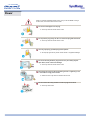
Unpacking
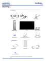
Please make sure the following items are included with your monitor. If any items are missing, contact
your dealer.
Power Cord
Remote Control /
Batteries (AAA X 2)
User's Guide CD
Signal Cable
(15 pin D-Sub)
Cover-hole
Monitor
Warranty Card
(Not available in all locations)
RS232C CABLE
Temporary Stand
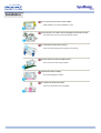
Sold separately
Wall Mount KIT
Speaker Set
PIVOT Installation CD
Contact a local Samsung Electronics service center to buy optional items.
Stand Kit
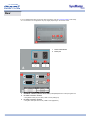
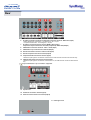
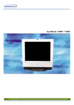
Front
For detailed information concerning the monitor functions, refer to User Controls under Adjusting Your
Monitor. The monitor's front configuration may vary slightly depending on the monitor model.
1. Auto button
6. Menu button
2. Source button
7. Power button
3. Exit button
8. Power indicator
4. Navigate button (Up-Down Button)
9. Remote Control Sensor
5. Adjust button (Left-Right Button)
/ Volume button
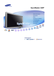
Rear
For detailed information concerning cable connections, refer to Connecting Cables under Setup.
The monitor's rear configuration may vary slightly depending on the monitor model.
1.
Power On/Off Switch
2.
Power port
3.
EXTERNAL CONTROL (RS232C Serial PORT) : MDC(Multiple Device Control) Program Port
4.
PC Video Connection Terminal
: Using D-Sub Cable (15 pin D-Sub) - RGB 1 mode (Analog PC)
5.
PC Video Connection Terminal
: Using DVI Cable (DVI-D to DVI-D) - RGB 2 mode (Digital PC)
Rear
6.
PC Video Connection Terminal / Component Connection Terminal : BNC cable (Input)
- RGB 3 (Analog PC) Connection : connecting B, G, R, H, V port
- Component Connection : connecting Pb, Y, Pr port
7.
PC Video Loopout Connection Terminal (RGB 3 (Analog PC)) /
Component Loopout Connection Terminal (Component) - BNC cable(Output)
8.
CVBS Video Connection Terminal : Video 1 mode (Input)
9.
CVBS Video Loopout Connection Terminal (Output)
10. S-Video Connection Terminal : Video 2 mode (Input)
11. S-Video Loopout Connection Terminal (Output)
12. Component Audio Connection Terminal (Input)
: When the input signal is connected to Terminal 6, the audio must be connect to this terminal only.
13. CVBS, S-Video Audio Connection Terminal (Input)
: When the input signal is connected to Terminal 8 or 10, the audio must be connect to this terminal
only.
Loopout Connection : Up to 5 monitors supported.
14. Speaker Out
15. PC Stereo Connection Terminal (Input)
16. Audio Line-out Connection Terminal (Output)
17. Kensington Lock
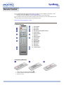
Remote Control
For detailed information of the Remote Control Unit functions, refer to Adjusting Your Monitor > User
Controls > User Control Buttons > Remote Control buttons.
The remote control's configuration may vary slightly depending on the monitor model.
The Remote control may function within a range of 0.23 to 33 feet (7cm to 10m) and 30 degrees to the
left and right of the monitor's Remote Control Reception sensor.
Button Names | Replacing Batteries | Usage
1. Button Names
1. Power button
2. Auto button
3. Mute button
4. VOL(Volume)and Up/Down buttons
5. Source button
6. Number buttons
7. PIP button
8. PIP Size button
9. P.Size button
10. Still button
11. Display button
12. Sleep button
13. Menu button
14. Exit button
15. Swap button
16. Location button
2. Replacing Batteries
1. Slide out the cover pressing part marked
.
2. Insert the batteries matching their polarities (+, -).
3. Slide in the cover.
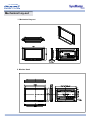
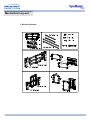
Mechanical Lay-out
1. Mechanical Lay-out
2. Monitor Head
Mechanical Lay-out
3. Stand
4. Speaker
Mechanical Lay-out
5. Mounting Bracket
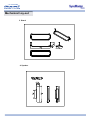
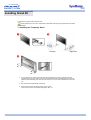
Installing Stand Kit
Only the supplied bolts should be used.
Samsung Electronics will not be responsible for damages caused by using a base other than those
specified.
1. Installing the Temporary Stand
Left stand
Right stand
1. A cover-protector is used to protect the hole at the bottom of the monitor, where the stand is
inserted. Be sure to remove the cover-protector when attaching the provided temporary stand or
stand kit (sold separately) and cover the hole using the cover-hole when attaching the wall mount
kit.
2. Set up the left and right stands respectively.
3. Put the stand into the hole at the bottom of the monitor.
Insert screw into the hole indicated and tighten. (M5 × 4)
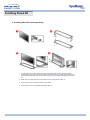
Installing Stand Kit
2. Installing Stand Kit (sold separately)
1. A cover-protector is used to protect the hole at the bottom of the monitor, where the stand is
inserted. Be sure to remove the cover-protector when attaching the provided temporary stand or
stand kit (sold separately) and cover the hole using the cover-hole when attaching the wall mount
kit.
2. Make sure you put the parts in the right direction and in the right place. (M5 × 4)
3. Put the stand into the hole at the bottom of the monitor.
4. Insert screw into the hole indicated and tighten. (M5 × 4)
Connecting Your Monitor
AV input devices like DVDs, VCRs or Camcorders as well as your computer may be connected to the
monitor. For detailed information on connecting AV input devices, refer to User Controls under
Adjusting Your Monitor.
Connecting to a Computer | Connecting to a VCR | Connecting to a DVD Player | Connecting a Camcorder
Connecting D-TV Set Top Box | Connecting Speaker | Connecting to an Audio System
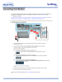
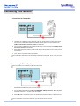
1. Connecting to a Computer
1. Connect the power cord for your monitor to the power port on the back of the monitor.
Trun on power switch.
2. Connect the signal cable to the PC Video Connection Terminal on your computer.
There are 3 ways to connect the signal cable to your monitor.
Choose one of the followings :
2-1. Using the D-sub (Analog) connector on the video card.
Connect the signal cable to the 15 pin D-sub Port on the back of your monitor.
2-2. Using the DVI (Digital) connector on the video card.
Connect the DVI Cable(DVI-D + DVI-D) to the DVI Port on the back of your Monitor.
2-3. Using the BNC (Analog) connector on the video card.
Connect the BNC Cable to the RGB 3 (COMPONENT VIDEO) IN terminal - B, G, R, H, V
port on the back of your Monitor.
DVI cable or BNC cable is optional.
3. Connect the audio cable for your monitor to the audio port on the back of your computer.
4. Turn on both your computer and the monitor.
Contact a local Samsung Electronics service center to buy optional items.
Connecting Your Monitor
2. Connecting to a VCR
1. AV input devices like VCRs or Camcorders are connected to the S-Video Connection Terminal or
CVBS Video Connection Terminal of the monitor using the S-VHS or BNC cable.
S-VHS or BNC cable is optional.
2. Connect the Audio (L) and Audio (R) terminals of a VCR or Camcorders to the monitor's CVBS, SVideo Audio Connection Terminal using audio cables.
3. Select Video 1 or Video 2 that is connected to a VCR or Camcorders using the Source button on
the monitor's front or remote control.
4. Then, start the VCR or Camcorders with a tape inserted.
3. Connecting to a DVD Player
1. Connect a set of audio cables between the Component Audio Connection Terminal on the
Monitor and the AUDIO OUT jacks on the DVD player.
2. Connect a BNC cable between the RGB 3 (COMPONENT VIDEO) IN terminal - Pb, Y, Pr port on
the Monitor and the Pb, Y, Pr jacks on the DVD player.
BNC cable is optional.
3. Select BNC that is connected to a DVD player using the Source button on the monitor's front or
remote control.
4. Then, start the DVD Player with a DVD disc inserted.
For an explanation of Component video, see your DVD player owner's manual.
Connecting Your Monitor
4. Connecting a Camcorder
1. Locate the A/V output jacks on the camcorder. They are usually found on the side or back of the
camcorder.
Connect a set of audio cables between the AUDIO OUTPUT jacks on the camcorder and the
CVBS, S-Video Audio Connection Terminal on the Monitor.
2. Connect a video cable between the VIDEO OUTPUT jack on the camcorder and the CVBS Video
Connection Terminal on the Monitor.
3. Select Video 1 that is connected to a Camcorder using the Source button on the monitor's front or
remote control.
4. Then, start the Camcorders with a tape inserted.
The audio-video cables shown here are usually included with a Camcorder. (If not, check your local
electronics store.) If your camcorder is stereo, you need to connect a set of two cables.
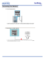
5. Connecting D-TV Set Top Box
The connections for a typical Set Top Box are shown below.
1. Connect a set of audio cables between the Component Audio Connection Terminal on the
Monitor and the AUDIO OUT jacks on the Set Top Box.
2. Connect a BNC cable between the RGB 3 (COMPONENT VIDEO) IN terminal - Pb, Y, Pr port on
the Monitor and the Pb, Y, Pr jacks on the Set Top Box.
3. Select BNC that is connected to a D-TV Set Top Box using the Source button on the monitor's front
or remote control.
For an explanation of Component video, see your Set Top Box owner's manual.
Connecting Your Monitor
6. Connecting Speakers
1. Connect the Left, Right audio speaker cable to the external speaker output jacks on the rear of the
Monitor, matching the red "+" and the black "-" ends of the cable with the diagram on the Monitor.
7. Connecting to an Audio System
1. Connect a set of audio cables between the AUX L, R jacks on the AUDIO SYSTEM and the Audio
Line-out Connection Terminal on the Monitor.
Multiple Display Control (MDC)
1. Introduction
2. Install
3. Beginning :
Main Screen | Port Setting | Port Change
4. Power Control
5. Input Source Control
6. Image Size Control :
RGB 1, 2, 3 | Video 1, 2, Component
7. Time Control
8. PIP Control :
PIP Size | PIP Source
9. Settings Control :
Picture | Picture RGB | Audio | Image Lock 1 |
Image Lock 2
10. Diagnostics
11. Troubleshooting
12. Settings Value Display In Multiple Display Mode
1.Introduction
A Multiple Display Control (MDC) is an application allowing various displays to be easily and simultaneously
operated on a PC. RS-232C, a standard of serial communication, is used for the communication between a
PC and a display. Therefore, a serial cable should be connected between the serial port on a PC and the
serial port on a display.
Multiple Display Control (MDC)
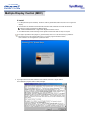
2. Install
1. PC Requirements (recommended) : Pentium II, 64M or greater RAM, 800 x 600, 256 color or higher PC
display.
2. OS: Windows 95, Windows 98, Windows ME, Windows 2000, Windows XP and XP Professional
Minimum system requirement for MDC Program
- Windows 98/ME/2000/XP : Support both English and Others version.
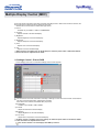
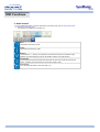
3. Click SETUP.EXE, and the following screen appears and the basic files for setup are copied.
The proper operation of this program is guaranteed only when it is used with Samsung SyncMaster
403T model and is not guaranteed when the user run this program with other models.
Some functions are not supported in SyncMaster 403T.
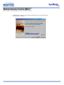
4. If you agree to the terms and conditions of the software, select the "I Agree" button.
Then installation program starts to install packages.
Multiple Display Control (MDC)
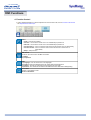
5. Select the folder in which you want to install the program and then click Install button. Now
installationation is completed.
Multiple Display Control (MDC)
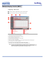
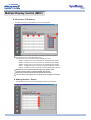
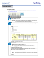
3. Beginning – Main Screen
Click Start > Program > Multiple Display Control to start the program.
Select a set to see the volume of the selected set within the slider.
Main Icons
Control Tools
Select Button
Remocon
Display Selection
Title
Info Grid
Comm. Status
1. Use the main icons to switch into each screen.
2. Click Select all or Clear to select or clear all displays.
3. Select a display from Display Selection.
4. Use Grid to view brief information on selected display.
5. Use Control Tools to control displays.
6. Allows you to enable or disable the remote control signal receiving function of the display unit.
7. The current title to be controlled is displayed.
8. Indicates the communication status between the MDC and the display.
Shows “Busy” while communicating and “Idle" when the communication is off.
<Note> The remote control Enable/Disable function operates whether or not the power is On/Off, and
this applies to all displays connected to the displays connected to the MDC However,
regardless of the status at the time the MDC is shut down, the remote control signal receiving
function of all displays is initialized to Enable when the MDC is closed.
Multiple Display Control (MDC)
3. Beginning – Port Setting
1. The Multiple Display Control uses only “Com1.” The Control does not function with any other ports.
2. To check which port is installed, go to Control Panel > System > Hardware > Device Manager > Ports.
3. If the port installed is Com2, change to Com1 in Windows 2000 (See next chapter). For all the other
operating systems, the change can be made from the BIOS Setup of your PC.
4. Use Exit to end the program. The Help menu shows how to use the program and general information about
the program.
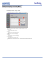
3. Beginning – Port Change
1. The Multiple Display Control uses only with Com1. It does not function with any other ports including
Com2.
2. You can change the port to “Com1” in Windows 2000 as follows.
3. Go to Control Panel > System > Hardware > Device Manager > Ports > Right Mouse Click > Properties >
Port Settings Tab > Advanced
4. Choose COM1
Multiple Display Control (MDC)
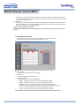
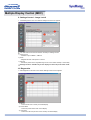
4. Power Control
1. Click Power Control of the main icons and the Power Control screen appears.
Info Grid shows some basic information necessary to Power Control.
1) Power Status
2) Input Source
3) Aspect Ratio
4) On Timer Status
5) Off Timer Status
2. Use the Select All button or Check Box to choose a display to control.
Power Control allows controlling some of the functions of the selected display.
1) Power On/Off
- Turns the power of the selected display On/Off.
Turns on each set at one second interval to prevent the power overload that might occur when many
sets turn on at the same time.
2) Volume Control
Multiple Display Control (MDC)
- Controls the volume level of the selected display. It receives the volume value of the selected display
from the sets and displays it in the slider. (When you cancel the selection or choose Select All, the value
returns to the default value 10)
3) Mute On/Off
- Turns the mute of the selected display On/Off . When selecting one set at a time, if the selected set is
already set to MUTE, you must mark the MUTE display. (If you choose undo the selections or choose
Select All, the values return to default settings.)
Power Control applies to all displays.
The Volume and Mute functions are available only for the displays for which the power status is
ON.
5. Input Source Control
1. Click Input Source of the main icons and the Input Source control screen appears.
Click Select All or use Check Box to select a display to control.
Info Grid shows some basic information necessary to Input Source Control.
1) Power Status
- Shows the power status of the current display.
2) Input Source
- Shows the Input Source currently in use.
3) Choose Input Source
- Change Input Source of the selected display.
• RGB 1 : Changes the Input Source of the selected display to RGB 1.
• RGB 2 : Changes the Input Source of the selected display to RGB 2.
• BNC(RGB 3) : Changes the Input Source of the selected display to RGB 3.
• BNC(Component) : Changes the Input Source of the selected display to Component.
• Video 1 : Changes the Input Source of the selected display to Video 1.
• Video 2 : Changes the Input Source of the selected display to Video 2.
Input Source Control applies only to the displays for which the power status is ON.
Multiple Display Control (MDC)
6. Image Size Control - RGB 1, 2, 3
1. Click Image Size of the main icons and the Image Size control screen appears.
Click Select All or use Check Box to select a display to control.
Info Grid shows some basic information necessary to Image Size Control.
1) Power
- Shows the power status of the current display.
2) Aspect
- Shows the current Image Size of the display in use.
3) Input Source
- Shows the current Input Source of the display in use.
4) Info Grid displays only the displays whose Input Source is RGB 1, 2, 3.
5) When you click Image Size, the RGB 1, 2, 3 tabs first appear.
- The Image Size Control button controls Image Size available for RGB 1, 2, 3.
6) Click the Video 1, 2, Component tab to control Image Size for respective Input Source.
7) Click to change Image Size of the selected display.
Image Size Control is available only for the displays for which power status is ON.
Multiple Display Control (MDC)
6. Image Size Control - Video 1, 2, Component
1. Click Image Size of the main icons and the Image Size control screen appears.
Info Grid shows some basic information necessary to Image Size Control.
1) Click the Video 1, 2, Component tab to adjust Image Size for Video 1, 2, Component.
Click Select All or use Check Box to select a display to control.
2) Info Grid displays only the display having Video 1, 2, Component as input source.
3) Switch Image Size of the selected display randomly.
4) You can also adjust Image Size for RGB 1, 2, 3 if you click on the RGB 1, 2, 3 tab.
5) Click to change Image Size of the selected display.
Image Size Control is available only for the displays for which power status is ON.
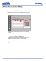
7. Time Control
1. Click Time of the main icons and the Time Control screen appears.
Info Grid shows some basic information necessary to Time Control.
1) Current Time
- Set the current time for the selected display (PC Time)
- To change the current time, first change the PC Time.
Multiple Display Control (MDC)
Current time is equivalent to PC time, If the Current time is not correct set the PC time
The shown current time will not be applien before pressing Apply button.
2) On Time Setup
- Set the hour, minute, AM/PM of On Time, Status, Source, volume of the selected display.
3) Off Time Setup
- Set the hour, minute, and AM/PM, Status for Off Timer of the selected display.
4) Shows the On Timer settings.
5) Shows the Off Timer settings.
Time Control is available only for the displays for which the power status is ON.
8. PIP Control - PIP Size
1. Click PIP of the main icons and the PIP control screen appears.
Click Select All or use Check Box to select a display to control.
Info Grid shows some basic information necessary to PIP Size Control.
1) Power
- Shows the power status of the current display.
2) PIP Size
- Shows the current PIP Size of the display in use.
3) PIP Source
- Shows the current PIP Source of the display in use.
4) When you click PIP, the PIP Size tabs first appear.
- The PIP Control button controls PIP Size available for RGB 1, 2, 3, Video 1, 2
5) Click the PIP Source tab to control PIP Source for respective Input source.
6) Click to change PIP Size of the selected display.
• OFF : Turns off the PIP of the selected display.
• PIP 1 : Turns on the PIP of the selected display and changes the size to PIP 1.
• PIP 2 : Turns on the PIP of the selected display and changes the size to PIP 2.
• Double 1 : Turns on the PIP of the selected display and changes the size to Double 1.
• Double 2 : Turns on the PIP of the selected display and changes the size to Double 2.
PIP Size can be controlled with turning on the monitor power.
The sets whose input signals are "Component" do not appear on the grid.
Multiple Display Control (MDC)
8. PIP Control - PIP Source
1. Click PIP of the main icons and the PIP control screen appears.
Info Grid shows some basic information necessary to PIP Source Control.
1) Click the PIP Source tab to adjust PIP Source.
Click Select All or use Check Box to select a display to control.
• RGB 1 : Changes the source of the PIP of the selected display to RGB 1.
• RGB 2 : Changes the source of the PIP of the selected display to RGB 2.
• RGB 3 : Changes the source of the PIP of the selected display to RGB 3.
• Video 1 : Changes the source of the PIP of the selected display to Video 1.
• Video 2 : Changes the source of the PIP of the selected display to Video 2.
PIP Source can be controlled with turning on the monitor power.
The Grid doesn't appear on Display that PIP doesn't work.
PIP Source can't be controlled on set that PIP doesn't work.
The sets whose input signals are "Component" do not appear on the grid.
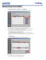
9. Settings Control - Picture
1. Click Settings of the main icons and the Settings Control screen appears.
Multiple Display Control (MDC)
Info Grid shows some basic information necessary to Settings Control. When each function is selected, the
set value of the selected function is displayed in the slide.
When Select All is selected, the default value (50) returns.
1) Picture
- Available only for VIDEO 1, VIDEO 2, COMPONENT.
2) Contrast
- Adjusts Contrast of the selected display.
3) Brightness
- Adjusts Brightness of the selected display.
4) Sharpness
- Adjusts Sharpness of the selected display.
5) Color
- Adjusts Color of the selected display.
6) Tint
- Adjusts Tint of the selected display.
Settings Control is available only for the displays for which the power status is ON and the default
value is 50 when no adjustments are made.
9. Settings Control - Picture RGB
1. Click Settings of the main icons and the Settings Control screen appears.
Info Grid shows some basic information necessary to Settings Control. When each function is selected, the
set value of the selected function is displayed in the slide.
When Select All is selected, the default value (50) returns.
1) Picture RGB
- Available only for RGB 1, RGB 2, RGB 3.
2) Contrast
- Adjusts Contrast of the selected display.
3) Brightness
- Adjusts Brightness for the selected display.
4) Color Temp.
- Adjusts Color Temperature of the selected display.
Settings Control is available only for the displays for which the power status is ON and the default
value is 50 when no adjustments are made.
This Control window is for the displays with RGB input source.
Multiple Display Control (MDC)
9. Settings Control - Audio
1. Click Settings of the main icons and the Settings Control screen appears.
Info Grid shows some basic information necessary to Settings Control. When each function is selected, the
set value of the selected function is displayed in the slide.
When Select All is selected, the default value (50) returns.
1) Audio
- Controls audio settings for all input sources.
2) Treble
- Adjusts Treble of the selected display.
3) Bass
- Adjusts Bass of the selected display.
4) Balance
- Adjusts Balance of the selected display.
5) Virtual Dolby
- Virtual Dolby Sound On/Off of the selected display.
6) Sound Select
- Select either Main or Sub when PIP is On.
Settings Control is available only for the displays for which the power status is ON and the default
value is 50 when no adjustments are made.
The Audio, Treble, Bass, Balance and Virtual Dolby features are available only in models that
support the speaker function.
Multiple Display Control (MDC)
9. Settings Control – Image Lock 1
1. Click Settings of the main icons and the Settings Control screen appears.
Info Grid shows some basic information necessary to Settings Control.
1) Image Lock 1
- Available only for RGB 1, RGB 3.
2) Coarse
- Adjusts Coarse of the selected display.
3) Fine
- Adjusts Fine of the selected display.
4) Position
- Adjusts Position of the selected display.
5) Auto Adjustment
- Self-Adjust to the incoming PC signal.
Settings Control is available only for the displays for which the power status is ON.
Multiple Display Control (MDC)
9. Settings Control – Image Lock 2
1. Click Settings of the main icons and the Settings Control screen appears.
Info Grid shows some basic information necessary to Settings Control.
1) Image Lock 2
- Available only for VIDEO 1, VIDEO 2.
2) Zoom
- Magnifies the size of the picture on screen.
3) Panning
- Moves the position of the magnified image on the screen either vertically or horizontally.
Settings Control is available only for the displays for which the power status is ON.
10. Diagnostics
1. Click Diagnostics of the main icons and the Settings Control screen appears.
1) SET ID
- Shows the ID of the currently connected display.
2) Power Status
- Shows the power status of the current display.
3) Lamp Time
- Shows the LCD Lamp On time of the currently connected display.
Multiple Display Control (MDC)
11. Troubleshooting
1. The display you wish to control does not appear on the Power Control Info Grid
- Check the connection of RS232C. (Check if it is properly connected to the Com1 port)
- Check the displays to see if any of the other displays connected have the same ID. If more than one
displays have the same ID, those displays are not properly detected by the program due to data conflict.
- Check if the Display Set ID is a number between 1 and 10. (Adjust using the Display menu)
Note : A Display Set ID must be a value between 1 and 10. If the value is out of the range, the MDC
system cannot control the display.
2. The display you wish to control does not appear on the other Control Info Grids
- Check to see if the display power is ON. (You can check this in Power Control Info Grid)
- Check if you can change the input source of the display.
3. The dialogue box appears repeatedly.
- Check to see if the display you wish to control is selected.
4. Both On Timer and Off Timer have been set but different time is showing.
- Apply current time to synchronize the display clocks.
5. The remote may not function properly when you turn off the remote Function, disconnect the RS-232C
cable, or exit the program in an Irregular manner. Rerun the program and turn the remote function again to
Restore normal functions.
6. <Note> This program may malfunction due to problems in communication circuits or interference from
electronic appliances nearby.
7. If you do need assistance, please call the phone number on the warranty card, the phone number on the
Information section or contact your dealer.
12. Settings Value Display In Multiple Display Mode
When there are more than one displays connected, the settings values are displayed as follows.
1. No selection: Displays the Factory Default Value.
2. Selected one display: Fetches and displays the settings value for the selected display.
3. Selected one display (ID1) and add another display (ID3): The program, which was displaying the settings
value of ID 1, fetches and displays the value of ID3.
4. Selected all sets using Select All: Returns to the Factory Default Value.
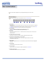
User control buttons
The control button configuration may vary slightly depending on the monitor model.
| Monitor Buttons |
For more information about screen adjustment, refer to On-Screen Display.
1. Auto button
Press to self-adjust to the incoming PC signal. The values of fine,coarse and position are adjusted
automatically.
To make the automatic adjustment function sharper, execute the 'AUTO' function while the AUTO
PATTERN is on. (Press here to view an animation about Auto Adjustment.)
2. Source button
Turns on the indicator to indicate the currently displayed input signal.
(Press here to view Screen Mode Switching Animation Clips.)
3. Exit button
When screen adjustment menu is on : Exit button exits from the menu screen or closes screen
adjustment menu.
4. Navigate button (Up-Down Button)
Moves from one menu item to another vertically or adjusts selected menu values.
5. Adjust button (Left-Right Button) / Volume button
Moves from one menu item to another horizontally or adjusts selected menu values.
Also adjusts the audio volume.
6. Menu button
When screen adjustment menu is on: Use this button to open the OSD and activate a highlighted
menu item.
7. Power button
Use this button to turn the monitor on and off.
8. Power indicator
Lights up when you turn the power on. Refer to Specifications > PowerSaver.
9. Remote control sensor
Aim the remote control towards this spot on the Monitor.
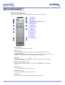
User control buttons
| Remote Control Buttons |
For more information on the screen adjustment functions, refer to On-Screen Display.
1. Power button
2. Auto button
3. Mute button
4. VOL(Volume)and Up/Down buttons
5. Source button
6. Number buttons
7. PIP button
8. PIP Size button
9. P.Size button
10. Still button
11. Display button
12. Sleep button
13. Menu button
14. Exit button
15. Swap button
16. Location button
1. Power button
Use this button to turn the monitor on and off.
2. Auto button
Press to self-adjust to the incoming PC signal. The values of fine,coarse and position are
adjusted automatically.
To make the automatic adjustment function sharper, execute the 'AUTO' function while the AUTO
PATTERN is on. (Press here to view an animation about Auto Adjustment.)
3. Mute button
Pauses (mutes) the audio output temporarily. The audio resumes if Mute or Volume button is
pressed in the Mute mode.
4. VOL(Volume)and Up/Down buttons
Press to increase or decrease the volume. (Also used to make selections on the on-screen
menus.)
5. Source button
Press to display all of the available video sources.
6. Number buttons
In the MDC program, press the numbers to set an ID.
7. PIP button
Every time you push the button, the PIP window's signal source changes.
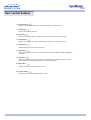
User control buttons
8. PIP Size button
Press to make the PIP window PIP 1, PIP 2, Double Screen 1, Double Screen 2.
9. P.Size button
Press to change the Screen size.
10. Still button
Press to stop the action during a particular scene. Press again to resume normal video.
11. Display button
Displays the resolution, frequency and input signal settings in the center of the screen.
12. Sleep button
Automatically shuts off the unit at a preset time.
13. Menu button
When screen adjustment menu is off: Use this button to open the OSD and activate a highlighted
menu item.
14. Exit button
On the User Controls screen, press to return to the previous menu screen or to exit the current
screen. Makes the PIP window disappear when selected in PIP mode.
15. Swap button
Switches the main screen to PIP and vice versa.
16. Location button
Moves the position of the PIP window on the screen.
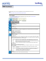
OSD Functions
Characters and icons become highlighted in blue during adjustment for each menu.
PC Control | Video Control | Audio Control | Function Control
1. PC Control
For detailed information on Screen Adjustment in the PC mode, refer to PC mode Screen
Adjustment Animation Clips.
Brightness
Adjust Brightness.
Contrast
Adjust Contrast.
Color Temperature
The tone of color can be changed. The individual color components are also user customizable.
1) Mode 1 : High Temperature.
2) Mode 2 : Middle Temperature.
3) Mode 3 : Low Temperature.
4) User Mode : User customizable.
Image
PC Screen Settings.
1) Image Lock
Image Lock is used to fine tune and get the best image by removing noises that creates unstable
images with jitters and shimmers. If satisfactory results are not obtained using the Fine adjustment,
use the Coarse adjustment and then use Fine again.
• Coarse : Removes noise such as vertical stripes. Coarse adjustment may move the screen
image area. You may relocate it to the center using the Horizontal Control menu.
• Fine :
Removes noise such as horizontal stripes. If the noise persists even after Fine tuning,
repeat it after adjusting the frequency (clock speed).
• Reset : Image lock and position parameters are replaced with the factory default values.
2) Image Size
Allows choosing from different image sizes.
Varies depending on the resolution or signal ratio. The Expand 1, Expand 2 and 1:1 functions work
only in PC RGB.
• Expand 1 : Performs full screen image expansion. (No change if the resolution is set at
maximum)
• Expand 2 : Performs image expansion while maintaining the vertical/horizontal aspect ratio of
the original video resolution. (No change if the resolution is set at maximum)
•1:1
Displays the image as created by the signal source.
(No change if the resolution is set at maximum.)
Position
This adjusts the screen location horizontally and vertically.
OSD Functions
2. Video Control
For detailed information on Screen Adjustment in the Video mode, refer to Video mode Screen
Adjustment Animation Clips.
You can use this function only if your screen mode is Video 1 or Video 2 or Component.
Brightness
Adjust Brightness.
Contrast
Adjusting Contrast.
Sharpness
Use to adjust the difference between the lightest and darkest areas on the display.
Color
Use to adjust the lightness/darkness on the display.
Tint
Use to add the natural tone to the display.
Reset
Picture parameters are replaced with the factory default values.
Image Size
Resizing the screen.
• Expand 1
• Expand 2
•1:1
• Panorama
• Zoom 1
• Zoom 2
OSD Functions
3. Audio Control
For detailed information on Screen Adjustment in the Audio mode, refer to Audio mode Screen
Adjustment Animation Clips.
Sound Select is available when the PIP is on.
Bass
Emphasize low frequency audio.
Treble
Emphasize high frequency audio.
Balance
Sound balance ==> Allows you to adjust the sound balance between the left and the right
speakers. (The ideal setting is 50 for the left speaker and 50 for the right speaker.)
Virtual Dolby
Virtual Dolby Sound On/Off (Virtual Dolby simulates the effect of the Dolby Surround sound
system, recreating the movie-theatre or concert-hall- quality sound.)
Sound Select
You can select either Main or Sub when PIP is On.
OSD Functions
4. Function Control
For detailed information on Screen Adjustment in the Function mode, refer to Function mode Screen
Adjustment Animation Clips.
ID (MDC Program)
Assigns individual ID to the SET.
1) ID Setup : Assigning distinctive IDs to the SET.
2) ID Input : Use to select the transmitter functions of the individual SET. Only the SET whose
ID corresponds to the transmitter setting becomes activated.
PIP
When external A/V devices such as VCR or DVD are connected to the monitor, PIP allows you to
watch video from such devices in a small window super-imposed on pc video signal. (On/Off)
1) On / Off
2) Size
Resizing the PIP Screen.
• PIP 1
• PIP 2
• Double Screen 1
• Double Screen 2
3) Source
Select the input source for the PIP.
PIP Settings
RGB 1
RGB 2
RGB 3
BNC
Component
Video 2
Video 1
RGB 1
RGB 2
X
X
X
X
O
O
X
X
X
X
O
O
RGB3
X
X
X
X
O
O
BNC
Component
X
X
X
X
X
X
Video 2
Video 1
O
O
O
X
X
X
O
O
O
X
X
X
4) Position : Change PIP window position.
Advanced Picture
1) Zoom (Available only for VIDEO 1, VIDEO 2)
• Zoom : Magnifies the size of the picture on screen.
• Pan : Moves the position of the magnified image on the screen either vertically or
horizontally.
2) DNIe (Digital Natural Image engine)
Samsung’s New Technology bring you more detailed image with contrast enhancement and white
enhancement. New image compensation algorithm gives brighter, cleare, to our customers.
DNIe technology will fit every signals into your eyes.
• Off :
Switches off the DNIe mode.
• Medium : Switches on the DNIe mode.
• High :
The screen is more clear than in Medium.
• Demo : The screen before applying DNIe appears on the right and the screen after applying
DNIe appears on the left.
3) Reset
OSD Functions
4. Function Control
For detailed information on Screen Adjustment in the Function mode, refer to Function mode Screen
Adjustment Animation Clips.
Timer
• Clock : Current Time Setting
• On Time : Use to set the monitor to turn on automatically at preset time.
• Off Time : Use to set the monitor to turn off automatically at preset time.
• On Time Source : Use to control the mode at the time the monitor turns on automatically.
• On Time Volume : Use to control the volume level at the time the monitor turns on
automatically.
• Sleep : Sleep Function
BNC Source
Select an input source from the BNC connection.
1) RGB 3
2) Component
OSD
1) Language : You can choose one of 10 languages.
2) Position : Move the OSD Window to the vertical and horizontal direction.
3) Halftone : Change the opaqueness of the background of the OSD.
4) Duration : The number of seconds that the OSD will remain visible before disappearing.
Information
Display current display mode.
Source / Resolution
Check before calling for service
Check the following items yourself before calling for service. Contact the service center for problems
that you cannot solve by yourself.
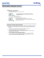
1. Self-Test Feature Check
Your monitor provides a self test feature that allows you to check whether your monitor is functioning
properly.
1. Turn off both your computer and the monitor.
2. Unplug the video cable from the back of the computer.
3. Turn on the monitor.
The figure shown below ("Check Signal Cable") appears on a black background when the monitor is
in its normal working condition though it does not sense any video signal: While in the Self-Test
mode, the LED power indicator remains green and the figure moves around on the screen.
Failure of any of the boxes to appear indicates a problem with your monitor. This box also appears
during normal operation if the video cable becomes disconnected or damaged.
4. Turn off your monitor and reconnect the video cable; then turn on both your computer and the
monitor.
If your monitor screen remains blank after using the previous procedure, check your video controller and
computer system; your monitor is functioning properly.
2. Video mode not supported
This indicates the display resolution or refresh rate is not properly set on your computer video card. Reboot
the computer in Safe Mode and select "Default" in the "Refresh Rate Unknown" box while setting Adapter
for Display Properties.
Contact the computer dealer or manufacturer for information on Safe Mode Booting.
Refer to Specifications > Preset Timing Modes for the resolutions or frequencies that are supported
by the monitor.
The screen sometimes remains black even though it does not show the message "Video mode not
supported." This indicates the monitor is set for a frequency out of range or the PowerSaver mode is on.
Check before calling for service
3. Maintenance and Cleaning
1. Maintaining the Monitor Case
Clean with a soft cloth after disconnecting the power cord.
z
z
Do not use benzene, thinner or other flammable substances.
We recommend a Samsung cleansing agent is used to prevent
damage to the screen.
2. Maintaining the Flat Panel Display Screen
Clean with a soft cloth (cotton flannel) smoothly.
z
z
Never use acetone, benzene or thinner.
(They may cause flaws or deformation of the screen surface.)
The user will be required to pay costs and related expenses for repair of
damages caused by the user.
4. Symptoms and Recommended Actions
A monitor recreates visual signals received from the PC. Therefore, if there is trouble with the PC or the
video card, this can cause the monitor to become blank, have poor coloring, noise, Video mode not
supported, etc. In this case, first check the source of the problem, and then contact a service center or
your dealer.
1. Check if the power cord and the cable are properly connected to the computer.
2. Check if the computer beeps more than 3 times when booting.
(If it does, request an after-service for the main board of the computer.)
3. If you installed a new video card or if you assembled the PC, check if you installed the adapter
(video) driver and the monitor driver.
4. Check if the scanning ratio of the video screen is set at 75Hz.
(Do not exceed 60Hz when using the maximum resolution.)
5. If you have problems in installing the adapter (video) driver, boot the computer in Safe Mode,
remove the Display Adapter at the "Control Panel, System, Device Administrator" and then
reboot the computer to reinstall the adapter (video) driver.
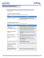
Problems and Solutions
The following table lists possible problems and their solutions. Before calling for service, check the
information in this section to see if you can remedy any problems yourself. If you do need assistance,
please call the phone number on the warranty card, the phone number on the Information section or
contact your dealer.
1. Problems related to Installation
Problems related to the monitor installation and their solutions are listed.
Problems
The monitor screen flickers.
Solutions
z
Check if the signal cable between the computer and the
monitor is securely connected and tightened. (Refer to
Connecting to a Computer)
2. Problems related to Screen
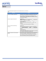
Problems related to the monitor screen and their solutions are listed.
Problems
Screen is blank and power
indicator is off
"Check Signal Cable" message
Solutions
z
z
z
"Video mode not supported"
message
z
z
Picture rolls vertically.
Image is not clear. Picture is
blurred.
z
z
z
z
The image is too light or too dark
z
Screen color is inconsistent.
z
Ensure that the power cord is firmly connected and the LCD
monitor is on. (Refer to the Connecting Your Monitor)
Ensure that the signal cable is firmly connected to the PC or
video sources. (Refer to the Connecting Your Monitor)
Ensure that the PC or video sources are turned on.
Check the maximum resolution and the frequency of the
video adaptor.
Compare these values with the data in the Preset Timing
Modes Chart.
Check if the signal cable is securely connected. Connect it
again securely.(Refer to Connecting to a Computer)
Run Frequency Coarse and Fine tuning.
Turn on again after removing all accessories (video
extension cable, etc.)
Set resolution and frequency to the recommended ranges.
(1280 x 768 @ 60Hz)
Adjust the Brightness and Contrast
(Refer to the Brightness, Contrast)
Adjust color using Mode under OSD Color Adjustment menu.
Color image is distorted with
dark shadows.
White color is poor.
Screen is blank and power
indicator light is steady green or
blinks every 0.5 or 1 seconds
z
z
The monitor is using its power management system.
Move the computer's mouse or press a key on the keyboard
Problems and Solutions
3. Problems related to Audio
Problems related to audio signals and their solutions are listed below.
Problems
No sound
Solutions
z
z
Sound level is too low.
z
z
Sound is too high pitched or too
low pitched
z
Ensure that the audio cable is firmly connected to both the
audio-in port on your monitor and the audio-out port on your
sound card. (Refer to the Connecting Your Monitor)
Check the volume level.
Check the volume level.
If the volume is still too low after turning the control to its
maximum, check the volume control on the computer sound
card or software program.
Adjust the Treble and Bass to appropriate level.
4. Problems related to Remote Control
Problems related to the remote control and their solutions are listed.
Problems
The remote control buttons do
not respond.
Items to check
z
z
z
z
z
Check the battery polarities (+/-).
Check if the batteries have been exhausted.
Check if the power is on.
Check if the power cord is securely connected.
Check if a special fluorescent or neon lamp is on in the
vicinity.
Q&A
Frequently asked questions are summarized here for your reference.
Question
How can I change the frequency?
Answer
Frequency can be changed by reconfiguring the video card.
Note that video card support can vary, depending on the
version of the driver used. (Refer to the computer or the video
card manual for details.)
How can I adjust the resolution?
Windows XP:
Reset resolution by clicking Control Panel
Theme
Display
Settings.
Windows ME/2000:
Set the resolution at the Control Panel
Settings.
Appearance &
Display
* Contact the video card manufacturer for details.
How can I set the Power Saving
function?
Windows XP:
Reset Power Saving parameters by clicking Control Panel
Appearance & Theme
Display
Screen Saver or
in the computer BIOS SETUP. (Refer to Windows/Computer
Manual)
Windows ME/2000:
Set the function at BIOS-SETUP of the computer or the screen
saver. (Refer to Windows/Computer Manual).
How can I clean the outer case/LCD
Panel?
Disconnect the power cord and then clean the monitor with a
soft cloth, using either a cleaning solution or plain water.
Do not leave any remains of the detergent nor scratch the
case. Do not allow any water to go inside the monitor.
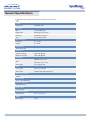
General Specifications
Design and specifications are subject to change without prior notice.
General
Model Name
SyncMaster 403T
LCD Panel
Size
39.6 inch (Diagonal)
Display area
862.080 (H) x 517.248 (V)
Pixel Pitch
0.6735 (H) x 0.6735 (V)
Type
a-si TFT active matrix
Synchronization
Horizontal
30 ~ 70 kHz
Vertical
56 ~ 85 Hz
Display Color
16,777,216 Colors
Resolution
Optimum resolution
1280 x 768 @ 60Hz
Maximum resolution
1280 x 768 @ 60Hz
Input Signal
Sync.
Video signal
Separate: TTL, P. or N.
Composite: TTL, P. or N.
0.7 Vp-p @ 75 ohm
Video
Color system
NTSC, PAL, SECAM
Video format
CVBS, S-VHS, RGB, Component
Maximum Pixel Clock
90 MHz
Power Supply
AC 90 ~ 264 V(50/60 Hz)
Power Consumption
230W (Maximum)
Power Saving
Less than 20W
Dimensions (WxDxH)
Without Stand
974 x 100 x 613 mm
Weight
Monitor body
26 kg
General Specifications
Environmental considerations
Operating
Temperature : 50°F ~ 104°F(10°C ~ 40°C)
Humidity : 10% ~ 80%, non-condensing
Storage
Temperature : -13°F ~113°F (-25°C ~ 45°C)
Humidity : 5% ~ 95%, non-condensing
Audio Characteristics
Audio Input 1
RCA Jack Red(R) White(L), 0.5Vrms (-9dB)
Audio Input 2
RCA Jack Red(R) White(L), 0.5Vrms (-9dB)
PC Audio Input
3.5ØStereo Jack, 0.5Vrms (-9dB)
Frequency
RF: 80Hz ~ 15kHz (at -3dB)
Response
A/V: 80Hz ~ 20kHz (at -3dB)
Plug and Play Capability
This monitor can be installed on any Plug & Play compatible system. Interaction of the monitor and computer
systems will provide the best operating conditions and monitor settings. In most cases, monitor installation
will proceed automatically, unless the user wishes to select alternate settings.
Dot Acceptable
TFT LCD panel manufactured by using advanced semiconductor technology with precision of 99.999%
above is used for this product. But the pixels of RED, GREEN, BLUE and WHITE color seem to be bright
sometimes or some of black pixels could be seen. This is not from bad quality and you can use it without
uneasiness.
The number of TFT LCD pixels :
2,949,120
PowerSaver
This monitor has a built-in power management system called PowerSaver. This system saves energy
by switching your monitor into a low-power mode when it has not been used for a certain amount of
time. The monitor automatically returns to normal operation when you move the computer's mouse or
press a key on the keyboard. For energy conservation, turn your monitor OFF when it is not needed, or
when leaving it unattended for long periods. The PowerSaver system operates with a VESA DPMS
compliant video card installed in your computer. Use a software utility installed on your computer to set
up this feature.
State
Normal Operation
Power saving mode
EPA
Power Switch off
Power Indicator
Green
Green, Blinking
Black
Power Consumption
Less than 230W
Less than 20W
Less than 1W
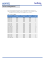
Preset Timing Modes
If the signal transferred from the computer is the same as the following Preset Timing Modes, the
screen will be adjusted automatically. However, if the signal differs, the screen may go blank while the
power LED is on. Refer to the video card manual and adjust the screen as follows.
Table 1. Preset Timing Modes
Display Mode
Horizontal Frequency
(kHz)
Vertical Frequency
(Hz)
Pixel Clock
(MHz)
Sync Polarity
(H/V)
MAC, 640 x 480
35.000
66.700
30.240
-/-
MAC, 832 x 624
49.730
75.000
57.284
-/-
VGA, 640 x 350
31.470
70.000
25.175
+/-
VGA, 720 x 400
31.470
70.000
28.322
-/+
VGA, 640 x 480
31.470
59.940
25.175
-/-
VGA, 640 x 480
37.861
72.809
31.500
-/-
VGA, 640 x 480
37.500
75.000
31.500
-/-
VGA, 640 x 480
43.269
85.008
36.000
-/-
WVGA, 848 x 480
29.820
60.000
31.490
+,-/+,-
SVGA, 800 x 600
35.160
56.200
36.000
+,-/+,-
SVGA, 800 x 600
37.880
60.300
40.000
+/+
SVGA, 800 x 600
48.100
72.200
50.000
+/+
SVGA, 800 x 600
46.875
75.000
49.500
+/+
SVGA, 800 x 600
53.674
85.061
56.250
+/+
XGA, 1024 x 768
48.363
60.004
65.000
-/-
XGA, 1024 x 768
56.480
70.000
75.000
-/-
XGA, 1024 x 768
60.023
75.029
78.750
+/+
XGA, 1024 x 768
68.677
84.997
94.500
+/+
WXGA, 1280 x 768
47.700
60.000
80.136
+,-/+,-
Service Center
U.S.A. :
Samsung Computer Products Customer Service
400 Valley Road, Suite 201, Mt. Arlington, NJ 07856
Tel. : (973)601-6000, 1-800-SAMSUNG (1-800-726-7864)
Fax. : (973)601-6001
http://www.samsungusa.com/monitor/
BRAZIL :
Samsung Eletronica da Amazonia Ltda.
R. Prof. Manoelito de Ornellas, 303, Terro B
Chacara Sto. Antonio, CEP : 04719-040
Sao Paulo, SP
SAC : 0800 124 421
http://www.samsung.com.br/
CANADA :
Samsung Electronics Canada Inc.
7037 Financial Drive
Mississauga, Ontario L5N 6R3
Tel. : 1-800-SAMSUNG (1-800-726-7864)
Fax. : (905) 542-1199
http://www.samsung.ca/
COLOMBIA :
Samsung Electronics Colombia
Cra 9 No 99A-02 Of. 106
Bogota, Colombia
Tel.: 9-800-112-112
Fax: (571) 618 - 2068
http://www.samsung-latin.com/
e-mail : [email protected]
PANAMA :
Samsung Electronics Latinoamerica( Z.L.) S.A.
Calle 50 Edificio Plaza Credicorp, Planta Baja
Panama
Tel. : (507) 210-1122, 210-1133
Tel : 800-3278(FAST)
http://www.samsung-latin.com/
PERU
Servicio Integral Samsung
Av.Argentina 1790 Lima1. Peru
Tel: 51-1-336-8686
Fax: 51-1-336-8551
http://www.samsungperu.com/
GERMANY :
TELEPLAN Rhein-Main GmbH
Feldstr. 16
64331 Weiterstadt
T. 06151/957-1306
F. 06151/957-1732
* EURO 0,12/MIN.
http://www.samsung.de/
AUSTRALIA :
Samsung Electronics Australia Pty Ltd.
Customer Response Centre
7 Parkview Drive, Homebush Bay NSW 2127
Tel : 1300 362 603
http://www.samsung.com.au/
ITALY :
Samsung Electronics Italia S.p.a.
Via C. Donat Cattin, 5
20063 Cernusco s/Naviglio (MI)
Servizio Clienti: 199.153.153
http://www.samsung-italia.com/
ESPAÑA :
Samsung Electronics Comercial Iberica, S.A.
Ciencies, 55-65 (Poligono Pedrosa) 08908
Hospitalet de Llobregat (Barcelona)
Tel. : (93) 261 67 00
Fax. : (93) 261 67 50
http://samsung.es/
United Kingdom :
Samsung Electronics (UK) Ltd.
Samsung House, 225 Hook Rise South
Surbiton, Surrey KT6 7LD
Tel. : (0208) 391 0168
Fax. : (0208) 397 9949
< European Service Center & National Service >
Stafford Park 12 Telford, Shropshire, TF3 3BJ
Tel. : (0870) 242 0303
Fax. : (01952) 292 033
http://samsungservice.co.uk/
THAILAND :
HAI SAMSUNG SERVICE CENTER
MPA COMPLEX BUILDING,1st-2nd Floor
175 SOI SUEKSA VIDHAYA SATHON SOI 12
SILOM ROAD ,SILOM,BANGRAK
BANGKOK 10500
TEL : 0-2635-2567
FAX : 0-2635-2556
http://www.samsungelectronics.co.th/
SOUTH AFRICA :
Samsung Electronics,5 Libertas Road, Somerset Office Park,
Bryanston Ext 16. Po Box 70006, Bryanston,2021, South Africa
Tel : 0027-11-549-1621
Fax : 0027-11-549-1629
http://www.samsung.co.za/
UKRAINE :
SAMSUNG ELECTRONICS REPRESENTATIVE OFFICE IN UKRAINE
4 Glybochitska str.
Kiev, Ukraine
Tel. 8-044-4906878
Fax 8-044-4906887
Toll-free 8-800-502-0000
http://www.samsung.com.ua/
SWEDEN/DENMARK/NORWAY/FINLAND :
Samsung Electronics AB
Box 713
S-194 27 UPPLANDS VÄSBY
SVERIGE
Bes?sadress : Johanneslundsv?en 4
Samsung support Sverige: 020-46 46 46
Samsung support Danmark : 8088-4646
Samsung support Norge: 8001-1800
Samsung support Finland: 0800-118001
Tel +46 8 590 966 00
Fax +46 8 590 966 50
http://www.samsung.se/
HUNGARY :
Samsung Electronics Magyar Rt.
1039, Budapest, Lehel u. 15-17.
Tel: 36 1 453 1100
Fax: 36 1 453 1101
http://www.samsung.hu/
FRANCE :
SAMSUNG ELECTRONICS FRANCE Service
Paris Nord 2
66 rue des Vanesses
BP 50116 Villepinte
95950 Roissy CDG Cedex
Tel : 08 25 08 65 65
Fax : 01 48 63 06 38
http://www.samsungservices.com/
PORTUGAL :
SAMSUNG ELECTRONICA PORTUGUESA S.A.
Rua M?io Dioniso, No2 - 1?Drt. 2795-140 LINDA-A-VELHA
Tel. 214 148 114/100 Fax. 214 148 133/128
Free Line 800 220 120
http://www.samsung.pt/
Service Center
NETHERLANDS/BELGIUM/LUXEMBOURG :
Samsung Electronics Benelux B. V.
Fleminglaan 12 2289 CP Rijiswijk, NEDERLANDS
Service and informatielijn ;
Belgium :0800-95214, http://www.samsung.be/
Netherlands : 0800-2295214, http://www.samsung.nl/
CHILE :
SONDA S.A.
Teatinos 550, Santiago Centro, Santiago, Chile
Fono: 56-2-5605000 Fax: 56-2-5605353
56-2-800200211
http://www.sonda.com/
http://www.samsung.cl/
MEXICO :
Samsung Electronics Mexico S.A. DE C.V.
Saturno No.44, Col. Nueva Industrial Vallejo
Gustavo A. Madero C.P. 07700, Mexico D.F. Mexico
Tel. 52 55 57 47 51 00
Fax. 52 55 57 47 52 02
RFC: SEM950215S98
http://www.samsung.com.mx/
IMPORTADO POR: SAMSUNG ELECTRONICS MEXICO. S.A. DE C.V.
SATURNO NO.44, COL. NUEVA. INDUSTRIAL VALLEJO
GUSTAVO A. MADERO C.P. 07700, MEXICO D.F. MEXICO
TEL. 52-55-5747-5100
RFC: SEM950215S98
EXPORTADO POR: SAMSUNG ELECTRONICS CO.,LTD.
JOONG-ANG DAILY NEWS BLDG.
7 SOON-WHA-DONG CHUNG-KU,
C.P.O BOX 2775, 1144 SEOUL, KOREA
Terms
Sync Signal
Sync (Synchronized) Signals refer to the standard signals that are required to display desired colors on
the monitor. They are divided into Vertical and Horizontal Sync Signals. These signals display normal
color images by the set resolution and frequency.
Types of Sync Signals
Separate
This is a scheme of transmitting individual vertical sync signals to the monitor.
Composite
This is a scheme of combining vertical sync signals into one composite signal
and transmitting it to the monitor. The monitor displays the color signals by
separating the composite signal into original color signals.
Sync On Green
This scheme does not use sync signals. Instead, it combines horizontal and
vertical sync signals into a Green signal and transmits to the monitor. It is mainly
used for workstations.
Dot Pitch
The image on a monitor is composed of red, green and blue dots. The closer the dots, the higher the
resolution. The distance between two dots of the same color is called the 'Dot Pitch'. Unit: mm
Vertical Frequency
The screen must be redrawn several times per second in order to create and display an image for the
user. The frequency of this repetition per second is called Vertical Frequency or Refresh Rate. Unit: Hz
Example: If the same light repeats itself 60 times per second, this is regarded as 60 Hz. In this case,
flickering of the screen can be detected. To avoid this problem, there is a Flicker-free Mode
using a vertical frequency over 70 Hz.
Horizontal Frequency
The time to scan one line connecting the right edge to the left edge of the screen horizontally is called
Horizontal Cycle. The inverse number of the Horizontal Cycle is called Horizontal Frequency. Unit: kHz
Interlace and Non-Interlace Methods
Showing the horizontal lines of the screen from the top to the bottom in order is called the Non-Interlace
method while showing odd lines and then even lines in turn is called the Interlace method. The NonInterlace method is used for the majority of monitors to ensure a clear image. The Interlace method is
the same as that used in TVs.
Plug & Play
This is a function that provides the best quality screen for the user by allowing the computer and the
monitor to exchange information automatically. This monitor follows the international standard VESA
DDC for the Plug & Play function.
Resolution
The number of horizontal and vertical dots used to compose the screen image is called 'resolution'. This
number shows the accuracy of the display. High resolution is good for performing multiple tasks as more
image information can be shown on the screen.
Example: If the resolution is 1024 X 768, this means the screen is composed of 1024 horizontal dots
(horizontal resolution) and 768 vertical lines (vertical resolution).
Multiple Display Control (MDC)
A Multiple Display Control (MDC) is an application allowing various displays to be easily and
simultaneously operated on a PC. RS-232C, a standard of serial communication, is used for the
communication between a PC and a display.
Regulatory
FCC Information | IC Compliance Notice | MPR II Compliance |
European Notice (Europe only) | PCT Notice | VCCI |
FCC Information
User Instructions
The Federal Communications Commission Radio Frequency Interference Statement includes the following
warning:
Note: This equipment has been tested and found to comply with the limits for a Class B digital device,
pursuant to Part 15 of the FCC Rules. These limits are designed to provide reasonable protection against
harmful interference in a residential installation. This equipment generates, uses, and can radiate radio
frequency energy and, if not installed and used in accordance with the instructions, may cause harmful
interference to radio communications. However, there is no guarantee that interference will not occur in a
particular installation. If this equipment does cause harmful interference to radio or television receptions,
which can be determined by turning the equipment off and on, the user is encouraged to try to correct the
interference by one or more of the following measures:
z Reorient or relocate the receiving antenna.
z Increase the separation between the equipment and receiver.
z Connect the equipment into an outlet on a circuit different from that to which the receiver is connected.
z Consult the dealer or an experienced radio/TV technician for help.
User Information
Changes or modifications not expressly approved by the party responsible for compliance could void the
user's authority to operate the equipment. If necessary, consult your dealer or an experienced
radio/television technician for additional suggestions. You may find the booklet called How to Identify and
Resolve Radio/TV Interference Problems helpful. This booklet was prepared by the Federal
Communications Commission. It is available from the U.S. Government Printing Office, Washington, DC
20402, Stock Number 004-000-00345-4.
The party responsible for product compliance:
SAMSUNG ELECTRONICS CO., LTD
America QA Lab of Samsung
3351 Michelson Drive,
Suite #290, Irvine, CA92612 USA
Tel) 949-975-7310
Fax) 949-922-8301
Warning
User must use shielded signal interface cables to maintain FCC compliance for the product.
Provided with this monitor is a detachable power supply cord with IEC320 style terminations. It may be
suitable for connection to any UL Listed personal computer with similar configuration. Before making the
connection, make sure the voltage rating of the computer convenience outlet is the same as the monitor
and that the ampere rating of the computer convenience outlet is equal to or exceeds the monitor voltage
rating.
For 120 Volt applications, use only UL Listed detachable power cord with NEMA configuration 5-15P type
(parallel blades) plug cap. For 240 Volt applications use only UL Listed Detachable power supply cord with
NEMA configuration 6-15P type (tandem blades) plug cap.
IC Compliance Notice
This Class B digital apparatus meets all requirements of the Canadian Interference-Causing Equipment
Regulations of ICES-003.
Cet appareil Numérique de classe B respecte toutes les exigences du Règlemont NMB-03 sur les
équipements produisant des interférences au Canada.
Regulatory
MPR II Compliance
This monitor complies with SWEDAC(MPR II) recommendations for reduced electric and magnetic fields.
European Notice (Europe only)
Products with the CE marking comply with the EMC Directive(89/336/EEC), (92/31/EEC), (93/68/EEC) and
the Low Voltage Directive (73/23/EEC) issued by the Commission of the European Community.
Compliance with these directives implies conformity to the following European Norms:
z EN55022:1998+A1:2000 - Radio Frequency Interference
z EN55024:1998 - Electromagnetic Immunity of Information Technology Equipment
z EN61000-3-2:1995+A1/A2:1998 - Power Line Harmonics
z EN61000-3-3:1995 - Voltage Fluctuations
PCT Notice
VCCI
This is a Class B product based on the standard of the Voluntary Control Council for Interference by
Information Technology Equipment (VCCI). If this is used near a radio or television receiver in a domestic
environment, it may cause radio interference. Install and use the equipment according to the instruction
manual.
Natural Color
Natural Color Software Program
One of the recent problems in using a computer is that the color of the images printed out by a printer or
other images scanned by a scanner or a digital camera are not the same as those shown on the monitor.
The Natural Color S/W is the very solution for this problem. It is a color administration system developed
by Samsung Electronics in association with Korea Electronics & Telecommunications Research Institute
(ETRI). This system is available only for Samsung monitors and makes the color of the images on the
monitor the same as the printed or scanned images.
For more information, refer to Help (F1) in the software program.
How to install the Natural Color software
Insert the CD included with the Samsung monitor into the CD-ROM Drive. Then, the initial screen of the
program installation will be executed. Click Natural Color on the initial screen to install the Natural Color
software. To install the program manually, insert the CD included with the Samsung monitor into the CDROM Drive, click the [Start] button of Windows and then select [Execute].
Enter D:\color\eng\setup.exe and then press the <Entrer> key.
(If the drive where the CD is inserted is not D:\, enter the applicable drive.)
How to delete the Natural Color software program
Select [Setting]/[Control Panel] on the [Start] menu and then double-click [Add/Delete a program].
Select Natural Color from the list and then click the [Add/Delete] button.
For Better Display
For Better Display
1. Adjust computer resolution and screen injection rate (refresh rate) in control panel of computer as
described below to enjoy the best quality of picture. You can have an uneven quality of picture in
the screen if the best quality of picture is not provided in TFT-LCD.
{
{
Resolution: 1280 x 768
Vertical frequency (refresh rate): 60 Hz
2. TFT LCD panel manufactured by using advanced semiconductor technology with precision of
99.999% above is used for this product. But the pixels of RED, GREEN, BLUE and WHITE color
seem to be bright sometimes or some of black pixels could be seen. This is not from bad quality
and you can use it without uneasiness.
{
For example, the number of TFT LCD pixels that is contained in this product are 2,949,120.
3. When you clean the monitor and the panel outside, please apply the recommended small amount
of cleaner by using soft and dry cloth and polish it. Let LCD area not to be forced but to be
scrubbed out softly. If excessive force is applied, you can have a stain on it.
4. If you are not satisfied with the quality of picture, you can get better quality of picture by executing
"auto adjustment function" in display screen that is appeared as window termination button is
pressed. If there's still noise after automatic adjustment, use FINE/COARSE adjustment function.
5. If you view a fixed screen for an extended period of time, residual image or blurriness may appear.
Change the mode to energy save or set a screensaver to moving picture when you need to be
away from the monitor for an extended period of time.
Authority
Information in this document is subject to change without notice.
© 2003 Samsung Electronics Co., Ltd. All rights reserved.
Reproduction in any manner whatsoever without the written permission of Samsung Electronics Co., Ltd. is
strictly forbidden.
Samsung Electronics Co., Ltd. shall not be liable for errors contained herein or for incidental or consequential
damages in connection with the furnishing, performance, or use of this material.
Samsung is the registered trademark of Samsung Electronics Co., Ltd.; Microsoft, Windows and Windows
NT are registered trademarks of Microsoft Corporation; VESA, DPMS and DDC are registered trademarks of
Video Electronics Standard Association; All other product names mentioned herein may be the trademarks or
registered trademarks of their respective owners.