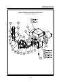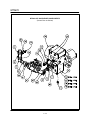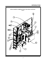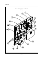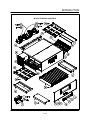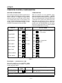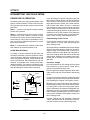
1
MT3870
CONVEYOR OVEN
SERVICE AND REPAIR MANUAL
BLODGETT OVEN COMPANY
www.blodgettcorp.com
50 Lakeside Avenue, Box 586, Burlington, Vermont 05402 USA Telephone (802) 658Ć6600 Fax: (802)864Ć0183
PN M7489 Rev B (6/01)
1996 - G.S. Blodgett Corporation All rights reserved.
Duplication of the information in this manual is prohibited without the consent of the Blodgett Service Department.
TABLE OF CONTENTS
1. INTRODUCTION
Oven Specifications . . . . . . . . . . . . . . . . . . . . . . . . . . . . . . . . . . . . . . . . . . . . . . . . . . . . . . . . . . . . . . .
Ventilation Requirements . . . . . . . . . . . . . . . . . . . . . . . . . . . . . . . . . . . . . . . . . . . . . . . . . . . . . . .
Electrical Specifications . . . . . . . . . . . . . . . . . . . . . . . . . . . . . . . . . . . . . . . . . . . . . . . . . . . . . . . .
Gas Specifications . . . . . . . . . . . . . . . . . . . . . . . . . . . . . . . . . . . . . . . . . . . . . . . . . . . . . . . . . . . .
Illustrated Parts Lists . . . . . . . . . . . . . . . . . . . . . . . . . . . . . . . . . . . . . . . . . . . . . . . . . . . . . . . . . . . . . .
1-1
1-1
1-1
1-2
1-3
2. ASSEMBLY
Oven Assembly Procedures . . . . . . . . . . . . . . . . . . . . . . . . . . . . . . . . . . . . . . . . . . . . . . . . . . . . . . . .
Return Air Diverters . . . . . . . . . . . . . . . . . . . . . . . . . . . . . . . . . . . . . . . . . . . . . . . . . . . . . . . . . . .
Air Nozzles . . . . . . . . . . . . . . . . . . . . . . . . . . . . . . . . . . . . . . . . . . . . . . . . . . . . . . . . . . . . . . . . . . .
Conveyor Rack Assemblies . . . . . . . . . . . . . . . . . . . . . . . . . . . . . . . . . . . . . . . . . . . . . . . . . . . .
Wire Conveyor Belt . . . . . . . . . . . . . . . . . . . . . . . . . . . . . . . . . . . . . . . . . . . . . . . . . . . . . . . . . . . .
Drive Chain . . . . . . . . . . . . . . . . . . . . . . . . . . . . . . . . . . . . . . . . . . . . . . . . . . . . . . . . . . . . . . . . . .
Air Plates . . . . . . . . . . . . . . . . . . . . . . . . . . . . . . . . . . . . . . . . . . . . . . . . . . . . . . . . . . . . . . . . . . . .
End Plugs . . . . . . . . . . . . . . . . . . . . . . . . . . . . . . . . . . . . . . . . . . . . . . . . . . . . . . . . . . . . . . . . . . . .
Conveyor Belt Tensioners . . . . . . . . . . . . . . . . . . . . . . . . . . . . . . . . . . . . . . . . . . . . . . . . . . . . . .
Crumb Pans . . . . . . . . . . . . . . . . . . . . . . . . . . . . . . . . . . . . . . . . . . . . . . . . . . . . . . . . . . . . . . . . . .
Mount Remote Control . . . . . . . . . . . . . . . . . . . . . . . . . . . . . . . . . . . . . . . . . . . . . . . . . . . . . . . . .
False Front (If Applicable) . . . . . . . . . . . . . . . . . . . . . . . . . . . . . . . . . . . . . . . . . . . . . . . . . . . . . .
2-1
2-1
2-1
2-1
2-1
2-2
2-2
2-2
2-2
2-2
2-2
2-2
3. OPERATION
Computer Controller . . . . . . . . . . . . . . . . . . . . . . . . . . . . . . . . . . . . . . . . . . . . . . . . . . . . . . . . . . . . . .
Control Description . . . . . . . . . . . . . . . . . . . . . . . . . . . . . . . . . . . . . . . . . . . . . . . . . . . . . . . . . . . .
Control Operation . . . . . . . . . . . . . . . . . . . . . . . . . . . . . . . . . . . . . . . . . . . . . . . . . . . . . . . . . . . . .
Programming Procedures . . . . . . . . . . . . . . . . . . . . . . . . . . . . . . . . . . . . . . . . . . . . . . . . . . . . . .
Display Information . . . . . . . . . . . . . . . . . . . . . . . . . . . . . . . . . . . . . . . . . . . . . . . . . . . . . . . . . . . .
Sequence of Operation . . . . . . . . . . . . . . . . . . . . . . . . . . . . . . . . . . . . . . . . . . . . . . . . . . . . . . . . . . . .
Domestic and General Export Ovens . . . . . . . . . . . . . . . . . . . . . . . . . . . . . . . . . . . . . . . . . . . .
CE Ovens . . . . . . . . . . . . . . . . . . . . . . . . . . . . . . . . . . . . . . . . . . . . . . . . . . . . . . . . . . . . . . . . . . . .
Oven Adjustments for Cooking . . . . . . . . . . . . . . . . . . . . . . . . . . . . . . . . . . . . . . . . . . . . . . . . . . . . .
Temperature . . . . . . . . . . . . . . . . . . . . . . . . . . . . . . . . . . . . . . . . . . . . . . . . . . . . . . . . . . . . . . . . . .
Conveyor Speed Time vs. Temperature . . . . . . . . . . . . . . . . . . . . . . . . . . . . . . . . . . . . . . . . . .
Air Flow Adjustments . . . . . . . . . . . . . . . . . . . . . . . . . . . . . . . . . . . . . . . . . . . . . . . . . . . . . . . . . .
3-1
3-1
3-1
3-2
3-2
3-3
3-3
3-5
3-7
3-7
3-7
3-7
4. CALIBRATION AND ADJUSTMENT
Convection Blower Motors . . . . . . . . . . . . . . . . . . . . . . . . . . . . . . . . . . . . . . . . . . . . . . . . . . . . . . . . .
To check motor rotation . . . . . . . . . . . . . . . . . . . . . . . . . . . . . . . . . . . . . . . . . . . . . . . . . . . . . . . .
To check lowĆlimit . . . . . . . . . . . . . . . . . . . . . . . . . . . . . . . . . . . . . . . . . . . . . . . . . . . . . . . . . . . . .
Regulated Gas Pressure . . . . . . . . . . . . . . . . . . . . . . . . . . . . . . . . . . . . . . . . . . . . . . . . . . . . . . . . . . .
Computer Control Configuration . . . . . . . . . . . . . . . . . . . . . . . . . . . . . . . . . . . . . . . . . . . . . . . . . . . .
Temperature Calibration . . . . . . . . . . . . . . . . . . . . . . . . . . . . . . . . . . . . . . . . . . . . . . . . . . . . . . . . . . .
4-1
4-1
4-1
4-2
4-3
4-5
i
TABLE OF CONTENTS
Belt Speed Calibration . . . . . . . . . . . . . . . . . . . . . . . . . . . . . . . . . . . . . . . . . . . . . . . . . . . . . . . . . . . .
Closed Loop System . . . . . . . . . . . . . . . . . . . . . . . . . . . . . . . . . . . . . . . . . . . . . . . . . . . . . . . . . .
Open Loop System - Single belt . . . . . . . . . . . . . . . . . . . . . . . . . . . . . . . . . . . . . . . . . . . . . . .
Open Loop System - Twin Belt . . . . . . . . . . . . . . . . . . . . . . . . . . . . . . . . . . . . . . . . . . . . . . . . .
motor control Board Adjustment . . . . . . . . . . . . . . . . . . . . . . . . . . . . . . . . . . . . . . . . . . . . . . . .
Rerating the Appliance . . . . . . . . . . . . . . . . . . . . . . . . . . . . . . . . . . . . . . . . . . . . . . . . . . . . . . . . . . . .
Checking the Firing Rate . . . . . . . . . . . . . . . . . . . . . . . . . . . . . . . . . . . . . . . . . . . . . . . . . . . . . . .
4-6
4-6
4-7
4-8
4-9
4-11
4-12
5. TROUBLESHOOTING
DC Drive System . . . . . . . . . . . . . . . . . . . . . . . . . . . . . . . . . . . . . . . . . . . . . . . . . . . . . . . . . . . . . . . . .
Computer Control System . . . . . . . . . . . . . . . . . . . . . . . . . . . . . . . . . . . . . . . . . . . . . . . . . . . . . . . . .
Heating System . . . . . . . . . . . . . . . . . . . . . . . . . . . . . . . . . . . . . . . . . . . . . . . . . . . . . . . . . . . . . . . . . .
Convection System . . . . . . . . . . . . . . . . . . . . . . . . . . . . . . . . . . . . . . . . . . . . . . . . . . . . . . . . . . . . . . .
5-1
5-2
5-3
5-5
6. TECHNICAL APPENDIX
Intermittent Ignition System . . . . . . . . . . . . . . . . . . . . . . . . . . . . . . . . . . . . . . . . . . . . . . . . . . . . . . . .
Principles of Operation . . . . . . . . . . . . . . . . . . . . . . . . . . . . . . . . . . . . . . . . . . . . . . . . . . . . . . . . .
Service Procedures . . . . . . . . . . . . . . . . . . . . . . . . . . . . . . . . . . . . . . . . . . . . . . . . . . . . . . . . . . .
Servicing the Invent Hood . . . . . . . . . . . . . . . . . . . . . . . . . . . . . . . . . . . . . . . . . . . . . . . . . . . . . . . . .
Illustrated Parts List . . . . . . . . . . . . . . . . . . . . . . . . . . . . . . . . . . . . . . . . . . . . . . . . . . . . . . . . . . .
Cleaning and Maintenance . . . . . . . . . . . . . . . . . . . . . . . . . . . . . . . . . . . . . . . . . . . . . . . . . . . . .
Servicing Access . . . . . . . . . . . . . . . . . . . . . . . . . . . . . . . . . . . . . . . . . . . . . . . . . . . . . . . . . . . . . .
Pressure Conversion . . . . . . . . . . . . . . . . . . . . . . . . . . . . . . . . . . . . . . . . . . . . . . . . . . . . . . . . . . . . . .
Conversion Factors . . . . . . . . . . . . . . . . . . . . . . . . . . . . . . . . . . . . . . . . . . . . . . . . . . . . . . . . . . . . . . .
Cooking Computer - Temperature vs Resistance . . . . . . . . . . . . . . . . . . . . . . . . . . . . . . . . . . . .
6-1
6-1
6-2
6-4
6-4
6-5
6-6
6-7
6-9
6-10
ii
Literature Addendum
Operation - Cooking Computer without Conveyor Control
NOTE: This addendum applies to tandem ovens only.
CONTROL DESCRIPTION
1. DIGITAL DISPLAY - Displays the time, temĆ
perature and controller related information.
2. OVEN ON/OFF - Controls power to the
oven.
3. NUMERIC KEYS - Used to enter numerical
data in the programming mode.
4. CLEAR KEY - Used to clear the display if an
error is made in the programming mode.
5. SET TEMP KEY - Used to view or program
the temperature setpoint.
6. ACT TEMP KEY - Used to view the current
oven temperature.
7. PROG/ENTER KEY - Used to enter and exit
the programming mode. Also used to lock
in programmed settings.
8. STATUS LAMPS - When lit indicate that the
fan or burners are operating.
NOTE:
This oven, supplied with remote
control, is equipped with an emerĆ
gency shut down switch.
Should you need to stop the heat
press the emergency switch.
WARNING:
Do not use the emergency switch as
a GENERAL on/off switch!
1
2
8
3
7
6
5
4
??????
Rev - 10/9/96
Page 1 of 3
Literature Addendum
Operation - Cooking Computer without Conveyor Control
OPERATION
OVEN SHUTĆDOWN
Turn the Computer Controller off (press and moĆ
mentarily hold the ON/OFF key). Since the Cool
Down circuit is already energized, the blower
motor(s) will continue to run until the oven
reaches approximately180F (82C). The blowĆ
er motor(s) will then automatically shut off.
To turn the oven on:
1. Turn the manual gas valve to ON.
2. Press and hold the ON/OFF key (2). The disĆ
play reads OFF when the oven is idle.
3. The display will flash WAIT LOW SET TIME 0.
4. The FAN and HEAT status lamps (9) light.
The fans begin to run. The heat rises to the
temperature setting stored in the computĆ
er's memory. The conveyor default time is 0.
COOLĆDOWN CIRCUIT
Blodgett Mastertherm conveyor ovens are
equipped with a coolĆdown feature for motor
shaft and bearing protection. When the oven
reaches approximately 180F (82C), the relay
contacts close allowing the blower motor(s) to
continue to run regardless of the Computer
Controller status. As noted previously, the blowĆ
er(s) will continue to run until the temperature
drops below 180F (82C).
To display the actual oven temperature:
1. Press the ACT TEMP key (6). The LED on
the key will light and the display reads ACĆ
TUAL nnnnF.
To view the temperature set point:
1. Press the SET TEMP key (5). The LED on the
key will light and the display flashes SET TEMP nnnnF.
NOTE:
This oven, supplied with remote
control, is equipped with an emerĆ
gency shut down switch.
To turn the oven off:
1. Press the ON/OFF key (2). The fans will conĆ
tinue to run until the oven cools to a safe
temperature.
Should you need to stop the heat
press the emergency switch.
WARNING:
Do not use the emergency switch
as a GENERAL on/off switch!
2
M7260.1
Rev - 9/5/96
Literature Addendum
Operation - Cooking Computer without Conveyor Control
PROGRAMMING PROCEDURES
Programming the Cook Time:
1. The conveyor belt default time is 0.
Programming the Temperature:
1. Press the PROGRAM/ENTER key (8).
2. Press the SET TEMP key (5). The display
reads PROGĆ? SET TEMPĆ? _ _ _ _F.
3. Use the NUMERIC keys (3) to enter the deĆ
sired temperature set point. The control disĆ
plays the numbers as they are entered. If an
error is made, press the CLEAR key (4) and
reĆenter the number.
4. Press the PROGRAM/ENTER key (8) again.
5. Press the PROGRAM/ENTER key (8) a secĆ
ond time to lockĆin the new temperature.
The new temperature setpoint will be stored
in the computer's memory.
Operation at the Programmed Settings:
1. Press and hold the ON/OFF key (2).
2. The FAN and HEAT status lamps (9) light.
The fans begin to run. The heat rises to the
temperature setting stored in the computĆ
er's memory.
3. The display will flash WAIT LOW SET TIME 0 until the programmed bake temperĆ
ature is reached. The HEAT lamp (9) will reĆ
main lit until the oven reaches the temperaĆ
ture set point.
4. The display reads READY and the HEAT
lamp (9) goes out.
5. The oven is now ready to accept product.
6. Press and hold the ON/OFF key (2) to turn
the oven off. The fans continue to run while
the oven cools to a safe temperature.
DISPLAY INFORMATION
WAIT LOW - indicates that the present oven
temperature is lower than the set point temĆ
perature. When the oven reaches the set
point temperature the display changes to
READY.
READY - indicates that the oven is ready to
accept product.
SET TIME 0 - indicates the current cook
time setting.
HIGH TIME - indicates that the temperature
is well above the set point. This usually occurs
when moving from a higher tā o a lower temperĆ
ature. Wait until the display reads ready beĆ
fore loading product.
HIGH TEMP LIMIT - indicates that the oven
temperature exceeds the high limit. The Over
Temperature Alarm buzzer will sound. Shut
the oven off and wait for the unit to cool down.
HIGH TEMP PANEL - indicates that the
control area reaches an excessive temperaĆ
ture. Shut the oven off and wait for the unit to
cool down.
PROBE OPEN PROBE SHORT - indicates
that the temperature sensor has failed. The
Alarm buzzer sounds. Shut the oven off and
contact a service representative.
NOTE:
This oven, supplied with remote
control, is equipped with an emerĆ
gency shut down switch.
Should you need to stop the heat
press the emergency switch.
WARNING:
Do not use the emergency switch
as a GENERAL on/off switch!
??????
Rev - 10/9/96
Page 3 of 3
CHAPTER 1
INTRODUCTION
MT3870
OVEN SPECIFICATIONS
VENTILATION REQUIREMENTS
Installations within the U.S.
The MT3870 requires a 15 Amp, 60HZ, 1F,
208Ć240VAC, 4 wire service consisting of L1, L2,
neutral and ground. See FIGURE 1. Use 90C wire
and size to National Electric or local codes.
The hood should completely cover the unit with an
overhang of at least 6" (15 cm) on all sides not adjaĆ
cent to a wall. The distance from the floor to the
lower edge of the hood should not exceed 7' (2.1
m). The ventilation system should replace 80% of
the exhaust volume with fresh make up air.
TABLE 1 should be used as a guideline.
Single
Double
Triple
CFM
1200Ć1650
2400Ć3300
3600Ć5000
M3/min
34 Ć 47
68Ć93
102Ć142
Installations outside the U.S.
The MT3870 requires a 15 Amp, 50Hz, 1F, 230
VAC, 3 wire service consisting of L1, neutral and
ground. See FIGURE 1. Use 90C wire and size
wire according to local codes.
CE approved installations
Connect the oven to a separate group 230V, 50 hz
with rigid connection and circuit breaker. The cirĆ
cuit breaker should disconnect all poles, including
neutral with a contact separation of at least 3 mm.
TABLE 1
ELECTRICAL SPECIFICATIONS
NOTE: The burner control unit is phase sensitive.
If the phase and neutral are switched the
control locks out.
NOTE: Three Phase hookup is not permitted.
WARNING: DO NOT INSTALL A HIGH LEG" TO
ANY CONVEYOR OVEN!
Connect exhaust fan connector 1 and 2. See
FIGURE 1. Connect phase + neutral + ground.
L1
Supply
N
120
L2
120
L1
208Ć240
Supply
Oven
U.S. Installations
L2
L1
N
Blodgett N
Connector
L
Connector
1
2
220Ć230
Oven
Export Installations
ÉÉ
ÉÉ
L3
N
2Ć4Ć92
ÉÉ
A1
2 s
A2
Fan
2 Air Pressure Regulator
1 Burner Control Solenoid
CE Approved Installations
FIGURE 1
1-1
Relay A
1
INTRODUCTION
GAS SPECIFICATIONS
GAS CONNECTIONS
GAS REQUIREMENTS
Domestic and General Export installations
The firing rate for the MT3870 is 150,000 BTU/Hr.
(43.9 kW/Hr.)
The gas line should be large enough to accommoĆ
date the peak demand of all the gas appliances.
TABLE 2 reflects a straight line, 50 foot run with no
coupling restrictions and no other appliances
drawing service. Gas line installations MUST conĆ
form to National Fuel Gas Code NFPA 54/ANSI
Z223.1 Sec. 1.4 (Latest Edition). TABLE 2 should
be used as a guideline only.
NOTE: For natural gas meter sizing, consult your
local gas company to ensure that your meĆ
ter will provide the proper supply.
Installations within the U.S.
1. Add the total BTU's/hr of all the gas
appliances.
NOTE: For any pipe runs over 50 feet (15 m), conĆ
sult the factory.
2. Convert BTU's to cubic ft/hr using the formula
Cu Ft/Hr = 1000 BTU/Hr for natural gas.
CE approved installations
3. Size the meter accordingly.
1. Connect the oven to the gas line with the propĆ
er type of gas according to Local and National
Installation Standards. See TABLE 2.
Installations outside the U.S.
1. Add the total M3/min of all the appliances.
2. Size the meter accordingly.
DOMESTIC AND GENERAL EXPORT
Natural Gas
Propane Gas
Single
3/4" line
3/4" line
Double
1Ć1/4" line
1 line
Triple
1Ć1/4" line
1Ć1/4" line
Orifice Size
#1
#29
Gas Line Sizing
Incoming Gas Pressure
W.C.
kPa
mbar
W.C.
kPa
mbar
7"
1.74
17.4
12.5"
3.11
31.1
5.5"
1.36
13.7
11"
2.73
27.4
Static
Operational
CE APPROVED UNITS
Type of
Gas
Inlet
Pressure
mbars
Burner Pressure
mbars
Injector
Air
Diameter Opening
mm
mm
Pilot
Injector
mm
Standard
Delivery
Value kW (HS)
G25
25
12
5,80
16
2 x 0,63
46 Nat. Gas
G20
20
8
5,80
16
2 x 0,63
46 Nat. Gas
G20/G25
20/25
Totally Inscrewed
Pressure Regulator
5,15
16
2 x 0,63
46 Nat. Gas
G30
30/50
17
3,48
16
2 x 0,30
46 Butane
G31
30/37/50
24
3,48
16
2 x 0,30
46 Propane
TABLE 2
1-2
MT3870
ILLUSTRATED PARTS LISTS
ELECTRICAL COMPONENTS
NOTE: = ASAP Distributor Required Stocking Parts
Ref. Part
No. No.
1
1
Computer Control Kit, Closed
Loop SB (Qty 1)
FW525 Computer Control Kit, Closed
Loop SB (Qty 1)
(Reconditioned)
M6474
M5635
M3175
M7427
M7202
M3347
M3348
M3490
M3491
2
3
Ref. Part
No. No.
Description
4
M3349
Computer Control Kit, Open
Loop TB (Qty 1)
Decal, Lexan Control (Qty 1)
Probe, Temperature RTD, 500
OHMS (Qty 1)
Conversion Kit, Open Loop to
Closed Loop (Qty 1)
Cable, Computer Control, 25
Pin, 10' (Qty 1)
Cable, Computer Control, 9
Pin, 10' (Qty 1)
Cable, Computer Control, 25
Pin, 50' (Qty 1)
Cable, Computer Control, 9
Pin, 50' (Qty 1)
Harness, Inter-Connecting DC
Drive, 3-Wire (For 9 Pin)
(Qty 1)
M3353
Harness, Relay Board
(Open Loop) (For 25 Pin)
(Qty 1) (Before 9/15/95)
M7237
Harness, Relay Board (Closed
Loop) (For 25 Pin) (Qty 1)
(After 9/15/95)
M3314
Bracket, Computer Wall (Qty 1)
M5661
Bracket Assy., Cable Clamp
(Qty 1)
Pick Up, PV-2 (Qty 1) (After
9/15/95)
Board, Relay/Transformer
(Qty 1)
Relay, Control (Qty 4)
M0984
M7236
5
22672
6
M3352
Transformer, 120V to 24V
(Qty 1)
7
20349
Buzzer, 120V (Qty 1)
8
M3295
Thermostat, High Limit
(Manual Reset) (Qty 1)
9
M1362
Snap Disc, L140/20F, 2 Pole
SPST (Qty 1)
M2453
Snap Disc, L140/20F, 3 Pole
SPDT (Qty 1)
10
M0595
Switch, Air Pressure SPDT
(Qty 1)
11
M0152
Contact, Emergency Stop
Switch (Qty 1)
M3296
Activator, Emergency Stop
Switch (Mushroom Shape)
(Qty 1)
M3297
Nameplate, Emergency Stop
(Qty 1)
M0593
Terminal Block, 2 Pole (Qty 1or
CE Qty 2)
M2469
Fan, Axial 110 CFM 4 1/2" (Qty
4) (Before 11/14/95)
22718
Fan Guard & Hardware (Qty 3)
(Before 11/14/95)
M0572
Cord, Axial Fan 30" Power (Qty
4) (Before 11/14/95)
14
M6381
Blower, Cooling (Qty 1) (After
11/14/95)
15
M3136
Breaker, 7 AMP Circuit (Qty 4)
16
M2772
Breaker, 4 AMP Circuit (Qty 2)
M6590
Plate Assy., Control SB (Qty 1)
M7482
Plate Assy., Control TB (Qty 1)
M1694
Cord Set & Plug Assy., 10 Foot
(Qty 1)
12
13
1-3
Description
M0772
Receptacle, Twist Lock (Qty 1)
17
M0708
Contactor, 3 Pole, 120V Coil
(Qty 1)
18
M3322
Hood Interlock, Mechanical
(Qty 1)
INTRODUCTION
CONVEYOR COMPONENTS
NOTE: = ASAP Distributor Required Stocking Parts
* = Item is Too Large for UPS
Ref. Part
No. No.
19
20
M6338
Belt, Wire S/S (Total Length
38" SB (Per Foot) MT3870 18
FT, MT3855 16 FT)
M7889
Belt, Wire S/S (Total Length
18-1/2" TB (Per Foot)
MT3870 18 FT)
M7272
Tensioner (After Assy., Belt
MT3870 (Qty 2) 9/15/95)
21 M2379
24
Fuse, Line, 22 Bodine Board, 5
AMP, 125V (Qty 1)
M2316
Fuse, (Qty 1) 23 Armature,
Bodine Board, 200 MA, 250V
25 M2378
M2500
M0391
Brush Set, Bodine (Qty 1)
Chain, Drive & Order (SB SpecĆ
ify 2 FT or TB Specify 4 FT
M0112)
Masterlink, Drive Chain (Qty 1)
M6791
Guard, Drive 26 Chain SB (Qty
1)
M6482
Guard, Drive Chain TB (Qty 1)
* M3981
Conveyor (Before Assy., Drive
SB MT3870 (Qty 1) 9/15/95)
27 * M6154
* M3982
28 * M6155
Conveyor (After Assy., Drive SB
MT3870 (Qty 1) 9/15/95)
Conveyor (Before Assy., Idle
SB MT3870 (Qty 1) 9/15/95)
Conveyor (After Assy., Idle SB
MT3870 (Qty 1) 9/15/95)
* M7592
Conveyor Assy., Drive TB
MT3870 (Qty 1)
* M7593
Conveyor Assy., Idle TB
MT3870 (Qty 1)
* M4432
Conveyor (Qty 1) Assy., Drive
SB MT3855G (Before 11/14/95)
* M6777
Conveyor MT3855G Assy.,
Folding (Drive & Idle) SB (Qty
1) (After 11/14/95)
29
M2672
Shaft, Conveyor Drive (Qty 1)
30
M2673
Shaft, Conveyor Idle (Qty 1)
32 M0108
Motor, (SB Qty 1 or Conveyor
Drive, Bodine 130V TB Qty 2)
M0112
Conveyor (Qty 1) Assy., Idle SB
MT3855G (Before 11/14/95)
M0110
Capacitor, (SB Qty 1 or Speed
Control Board TB Qty 2)
1-4
Description
* M4433
31 M0109
Speed Control Board, Bodine
(Qty 1)
M2254
M3301
Ref. Part
No. No.
Description
Sprocket, Motor Drive, 12 Tooth
(Qty 1)
Sprocket, Conveyor Drive, 15
Tooth (Qty 1)
Sprocket, Conveyor Belt, 11
Tooth (Qty 18)
MT3870
CONVECTION COMPONENTS
NOTE: = ASAP Distributor Required Stocking Parts
Ref. Part
No. No.
Ref. Part
No. No.
Description
Description
33 M4224
Motor & Blower Assy. CW
MT3870 (Qty 2)
M1962
Hold Down, Nozzle MT3870
(Qty 1) (Before 9/15/95)
34 M4225
Motor & Blower Assy. CCW
MT3870 (Qty 2)
M7399
Hold Down, Nozzle MT3870
Qty 1) (After 9/15/95)
M5419
Motor & Blower Assy. CCW
MT3855G (Qty 3) (After
2/27/94)
M5486
Hold Down, Nozzle MT3855G
(Qty 1) (Before 11/14/95)
M2564
Capacitor, Motor MT3870
(Qty 4)
M7380
Hold Down, Nozzle MT3855G
(Qty 1) (After 11/15/95)
M3106
Diverter, Air (LH & RH) MT3870
(Qty 2)
M3106
Diverter, Air (LH & RH)
MT3855G (Qty 2) (Before
11/14/95)
M5179
Diverter, Air (LH & RH)
MT3855G (Qty 2) (Before
11/14/95)
36
NOTE: Call factory if MT3855G oven was
manufactured before 2/27/94 to verify
motor part number.
35
M5722
Insulation Kit for Blowers
MT3870 (Qty 1)
M7991
Insulation Kit for Blowers
MT3855G (Qty 1)
M6466
Nozzle Assy. w/ Diverter
MT3870 (Qty 14) Generic
M5453
Diverter, Air (Center) MT3855G
(Qty 1)(Before 11/14/95)
M5466
Nozzle Assy. w/ Diverter
MT3855G (Qty 12) (Before
11/14/95)
M7372
Diverter, Air (LH) MT3855G
(Qty 1) (After 11/14/95)
(See L-495 & L-496)
M7105
Nozzle Assy. w/ Diverter
MT3855G (Qty 6) (After
11/14/95) (See L-497)
M7374
Diverter, Air (RH) MT3855G
(Qty 1) (After 11/14/95)
(See L-495 & L-496)
M7106
Nozzle Assy. w/ Diverter
MT3855G (Qty 6)
(After 11/14/95) (See L-497)
M7373
Diverter, Air (Center) MT3855G
(Qty 1) (After 11/14/95)
(See L-495 & L-496)
AIR PLATES
NOTE: = ASAP Distributor Required Stocking Parts
Ref. Part
No. No.
Ref. Part
No. No.
Description
Description
37
M6470
Plate Assy., Air RH MT3870
Generic (Qty 1)
M5649
Plate Assy., Air LH (L to R)
MT3855G Generic (Qty 1)
38
M6469
Plate Assy., Air LH MT3870
Generic (Qty 1)
24613
Hook, Air Pan (Qty 1)
M5767
Plate Assy., Air RH (R to L)
MT3855G Generic (Qty 1)
M6597
Plate Assy., Block Off MT3870
Generic (Qty 6)
M5768
Plate Assy., Air LH (R to L)
MT3855G Generic (Qty 1)
M6079
Plate Assy., Block Off MT3855G
Generic (Qty 6)
M5648
Plate Assy., Air RH (L to R)
MT3855G Generic (Qty 1)
39
1-5
INTRODUCTION
GAS BURNER COMPONENTS
NOTE: = ASAP Distributor Required Stocking Parts
Ref. Part
No. No.
40
22132
Ref. Part
No. No.
Description
Description
Burner Assy. Complete (Specify
Model & Gas Type) (Qty 1)
63
21278
Nipple, Pipe 1/2 x 3-1/2
(Qty 1)
41 M0767
Blower Motor, Comb. w/ ConĆ
trol Box (Qty 1)
64
M3238
Tee, 1/2 x 1/2 x 1/4 (Qty 1)
42 M2383
Blower Motor, Combustion
(Qty 1)
43 M2381
Transformer, 120V to 24V
(Qty 1)
44 M2382
Relay, Time Delay (Qty 1)
45
M0454
Orifice, Main Burner LP (Qty 1)
45
M0455
65 23007
Spring, Solenoid Valve, LP to
Natural (Qty 1)
65 18612
Spring, Solenoid Valve, Natural
to LP (Qty 1)
23114
Conversion Kit, LP to Natural
MT3870 (Qty 1)
21389
Orifice, Main Burner Natural
(Qty 1)
Conversion Kit, Natural to LP
MT3870 (Qty 1)
M5259
46 M2727
Pilot Burner & Igniter Assy. LP
(Qty 1)
Conversion Kit, LP to Natural
MT3855G (Qty 1)
M5290
46 M2726
Pilot Burner & Igniter Assy.
Natural (Qty 1)
Conversion Kit, Natural to LP
MT3855G (Qty 1)
66 M0282
Valve, Manual Gas (Qty 1)
47
Shield, Pilot Burner (Qty 1)
67 M5495
Dual Solenoid/Pressure ReguĆ
lator, Nat 24V (Qty 1)
67 22190
Dual Solenoid/Pressure ReguĆ
lator, LP 24V (Qty 1)
68 M1054
Spark Box, Johnson (Qty 1)
21242
Connector Kit, Gas Flex 48"
(Qty 1)
21826
Connector Kit, Gas Flex 36"
(Qty 1)
M7280
Flame Tube Assy., MT3870
(Qty 1)
M7390
Flame Tube Assy., MT3855G
(Qty 1)
M6378
48 M0415
Flame Sensor (Qty 1)
49 M2690
Orifice, Pilot LP (Qty 1)
49 M0697
Orifice, Pilot Natural (Qty 1)
50
M0248
Tube, Pilot Aluminum 1/4"
(1.583 Feet)
51
M0959
Fitting, Compression 1/4
(Qty 2)
52
M2799
Union, Compression (Qty 1)
53
21225
Fitting, Elbow (Qty 1)
54
4588
Nipple, Pipe 3/4 x 1-3/8 Close
(Qty 3 or CE Qty 2)
55
M0280
Tee, 3/4 x 3/4 x 1/4 (Qty 1)
56
M0278
Bushing, 1/4 x 1/8 Hex (Qty 2)
57
M0281
Plug, Pipe 1/8 Black (Qty 2)
58
17874
Ell, Black 1/2 x 3/4 (Qty 1)
59
M0590
Nipple, Pipe 1/2 x 2-1/2
(Qty 1)
60
M0279
Union, 1/2 Inch Black (Qty 1)
61
1949
Nipple, Pipe 1/2 x 1-3/16
Close (Qty 1)
62
M0317
Elbow, 1/2 Inch Street 90 Deg
(Qty 1)
69
1-6
MT3870
EXTERIOR COMPONENTS
NOTE: = Doors are not returnable
Ref. Part
No. No.
M2868
M2188
Ref. Part
No. No.
Description
Door Assembly, Pull Down S/S
(used w/enclosed Greenheck
hood system) (Qty 1)
Handle Kit, Door 2" (used
w/M2868) (Qty 1)
79
Description
M7575
Extension Assy., Product 15"
(LaRosa's) (Qty 1)
M2824
Crumb Pan, Idle MT3870
(Qty 1) (Before 9/15/95)
M6168
Crumb Pan, Idle MT3870
(Qty 1) (After 9/15/95)
M2823
Crumb Pan, Drive MT3870
(Qty 1) (Before 9/15/95)
M6167
Crumb Pan, Drive MT3870
(Qty 1) (After 9/15/95)
M6910
Crumb Pan, Idle MT3855G
(Qty 1)
M6906
Crumb Pan, Drive MT3855G
(Qty 1)
M5612
Plug Assy., Lower RH MT3870
Qty 1) (Before 9/15/95)
70 M3944
Door Assembly (used w/ false
front) (Qty 1)
71
M4275
Handle Kit, Door 22" (used w/
M3944) (Qty 1)
72
M1871
Plate, RH Pivot Slotted (Qty 1)
73
M1872
Plate, LH Pivot Slotted (Qty 1)
74
M3602
Bracket Assy., Mounting (Qty 2)
75
M3603
Bracket Assy., Mounting (Qty 2)
M5475
Filter Assy., MT3855G (Qty 1)
(Before 11/14/ 95)
M3751
False Front Assy., MT3870
(Qty 1)
81
M7276
M4563
False Front Assy., MT3855G
(Qty 1)
Plug Assy., Lower RH MT3870
(Qty 1) (After 9/15/95)
82
M5612
M3751
Tape, Closed Cell Foam
Plug Assy., Lower LH MT3870
(Qty 1)
M5032
Chimney Kit, Single (Qty 1)
(Before 11/95)
M7386
Plug Assy., Lower MT3855G
(Qty 2)
M7464
Chimney Kit, Single (Qty 1)
(After 11/95)
83
M3116
Plug Assy., Upper MT3870 &
MT3855G (Qty 2)
M7160
Chimney Kit, Double (Qty 1)
(Before 11/95)
84
M2460
Air Curtain, Upper End Plug
(Qty 2)
M7463
Chimney Kit, Double (Qty 1)
(After 11/95)
M3728
Support Assy., Upper End Plug
RH MT3870 (Qty 2)
21390
Legs, 17-1/4" w/ Casters
(Double) (Set of 4)
M3729
Support Assy., Upper End Plug
LH MT3870 (Qty 2)
21391
Legs, 23-1/4" w/ Casters
(Single) (Set of 4)
M7149
M7150
14444
Casters, Cradle (Triple Oven)
(Set of 4)
Support Assy., Upper End Plug
RH MT3855G (Qty 2) Support
Assy., End Plug LH MT3855G
(Qty 2)
M3724
Handle, End Plug (Qty 2)
77
M3783
Stop, Product S/S (Qty 1)
22229
Stacking Assy., Double (Qty 1)
78
M3779
Extension Assy., Product 6"
(Qty 1)
M4633
M4223
Extension Assy., Product 10"
(Qty 1)
Panel & Filter Assy. (Qty 1)
MT3870 (All) & MT3855G
(Before 11/14/95)
76
80
85
1-7
INTRODUCTION
Ref. Part
No. No.
M5485
Panel & Filter Assy. MT3855G
(Qty 1) (After 11/14/95)
XXXXX
Control Box Cover w/ Louvers
MT3855G (Qty 1) (Before
11/14/95)
M6799
Control Box Cover w/ Access
Door MT3855G (Qty 1) (After
11/14/95)
XXXXX
Ref. Part
No. No.
Description
Control Box Cover w/ Louvers
MT3870 (Qty 1) (Before
9/15/95)
1-8
Description
86
M7266
Control Box Cover w/ Access
Door MT3870 (Qty 1)
(After 9/15/96)
87
M6035
Latch, Access Door (Qty 1)
M2689
Body Back, MT3870 (Qty 1)
(Before 9/15/95)
M7254
Body Back, MT3870 (Qty 1)
(After 9/15/95)
M4248
Body Back, MT3855G (Qty 1)
MT3870
EXCLUSIVE TO EXPORT
NOTE: = ASAP Distributor Required Stocking Parts
Ref.
No.
Part
No.
88
M2276
Burner Assy., Complete
(Qty 1)
89
M4597
Motor & Blower Assy., CW
MT3870 (Qty 2)
90
M4598
Motor & Blower Assy., CCW
MT3870 (Qty 2)
91
M6000
Dual Solenoid/Pressure
Regulator, Nat. (Qty 1)
91
M6001
Dual Solenoid/Pressure
Regulator, LP (Qty 1)
92
M7283
Blower, Cooling Export (Qty 1)
93
M3128
Motor, Conveyor Drive
Bodine, 180V (Qty 1)
113 M3168
Spark Box, 240V (Landis &
Gyr) (Qty 1) CE
94
M3153
Digital Speed Control Board,
Bodine (Qty 1)
114 M2247
Contactor, 240V, 50 HZ (Qty 1)
CE
95
M2630
Fuse, Line, Bodine Board, 500
MA (Qty 1)
115
XXXXX
Indicator Light (Qty 2) CE
96
M2316
18265
Indicator Light, 28V, Red,
Round (Qty 1) CE
116
16037
Indicator Light, 250V, Red,
Round (Qty 1) CE & Australia
117
16775
Relay, SPST, 240V, 30 Amp.
(Qty 1) CE
118
M3172
Timer, Fixed, 2 Second (Qty 1)
CE
119
M3173
Timer, Fixed, 10 Second (Qty
1) CE
M6589
Plate Assy., Control SB (Qty 1)
CE
M7323
Plate Assy., Control SB Qty 1)
Australia
M6982
Piping Assy. (Qty 1) CE
120
M6029
Connector, Liquid Tight (Qty
1) CE
121
10809
Nipple, Pipe 1/2 x 2 (Qty 1)
CE
122
M2835
Fitting, Elbow 90 Street 1/8"
(Qty 1) CE
123
M3443
Bushing, Adapter (Qty 2) CE
124
M2841
Fitting, Pressure Tap (Qty 2)
CE
Description
Fuse, Armature, Bodine
Board, 200 MA, 250V (Qty 1)
M5717
Board, Relay (Open Loop) SB
(Qty 1)
97
M7282
Board, Relay (Closed Loop)
SB (Qty 1)
98
M6025
Fuse, 25V 80 ma (Qty 1)
99
M6024
Transformer, 220V to 24V
(Qty 1)
100 20350
Buzzer, 240V (Qty 1)
101
R1580
Stop, End (Qty 1)
102
M6449
Filter, Noise (Qty 1) CE
103
M7880
Computer Control Kit, Closed
Loop SB (Qty 1) CE
104
M7888
Relay, 1 Second Time Delay
(Qty 1) CE
105
M2386
Blower Motor, Combustion
(Qty 1) CE
106
M7333
Pilot Burner & Ignitor Assy.,
LP (Qty 1) CE
106
M7334
Pilot Burner & Ignitor Assy.,
Nat. (Qty 1) CE
107
M2497
Switch, Push Button (Qty 1)
CE
1-9
Ref.
No.
Part
No.
Description
108
M2498
Switch, Contact (Qty 1) CE
109
M3330
Switch, Air Pressure DifferenĆ
tial (mbr) (Qty 1) CE
M2819
Switch, Air Pressure (in/wc)
(Qty 1) Australia
110
M0706
Orifice, Main Burner (Specify
MTD) (Qty 1) CE
111
R0164
Terminal Block, Power (Qty 2)
CE
112
R0166
Terminal Block, Ground
(Qty 1) CE
INTRODUCTION
MT3870 DOMESTIC & GENERAL EXPORT CONTROL BOX
(Control Plate and/or Gas Burner Components not Shown)
1-10
MT3870
MT3870 CE CONTROL BOX
(Control Plate and/or Gas Burner Components not Shown)
1-11
INTRODUCTION
MT3870 DOMESTIC GAS BURNER COMPONENTS
(Control Box not Shown)
1-12
MT3870
MT3870 CE GAS BURNER COMPONENTS
(Control Box not Shown)
1-13
INTRODUCTION
MT3870 DOMESTIC & GENERAL EXPORT SB CONTROL PLATE ASSY
(M6590)
1-14
MT3870
MT3870 CE SB CONTROL PLATE ASSY
(M6589)
1-15
INTRODUCTION
MT3870 EXTERIOR OVEN VIEW
1-16
MT3870
This page intentionally left blank.
1-17
CHAPTER 2
ASSEMBLY
MT3870
OVEN ASSEMBLY PROCEDURES
RETURN AIR DIVERTERS
WIRE CONVEYOR BELT
1. Slide the return air diverters into the oven and
clip to the lower rear of the baking cavity. The
edge of the diverter should be 3" (7.6 cm) from
the outside edge of the oven cavity.
NOTE: The conveyor belt has loops on all four
sides. The belt must be installed so the
loops travel as shown in FIGURE 2.
1. Thread the wire belt from the right side of the
oven, lower level first.
2. After pushing the belt through on the lower levĆ
el, leave about 12" (30.5 cm) hanging out on
the left side.
3. Take the remainder of the belt, loop it around
the right shaft, and push it through on the upĆ
per level. The two ends of the belt should be
approximately 6Ć9" (15Ć22 cm) past the left
shaft (right shaft if right to left travel is required)
on the upper level of the belt support.
IMPORTANT:
Note Orientation Of Return Air Diverters!
Side Belt Loops
FIGURE 1
Direction of
Travel
AIR NOZZLES
FIGURE 2
1. Install the nozzles from the center of the oven
to the ends. The bottom of the nozzle must fit
into the slot of the nozzle support located at the
front of the oven.
2. Secure the nozzle holdĆdown strip across the
inside front of the oven using the existing
screws attached to the oven wall.
4. Install the inner and outer master links as
shown in FIGURE 3.
Master
Link
CONVEYOR RACK ASSEMBLIES
1. Slide the drive side conveyor rack assembly
(with the sprocket on the end of the shaft) into
the support tracks.
2. Push until the end sprocket is inserted into the
control compartment.
3. Install the alignment bolt through the conveyor
and control box.
4. Slide the idle side conveyor rack assembly into
the support tracks from the exit end of the
oven.
Direction of
Travel
FIGURE 3
Unless otherwise specified, the conveyor travel is
factory set for leftĆtoĆright operation when facing
2-1
ASSEMBLY
END PLUGS
the front of the oven. If a direction change is reĆ
quired, the polarity of the drive motor must be reĆ
versed. To change the polarity of the drive motor,
disconnect the oven from the power source and inĆ
terchange the black and white motor leads at the
D.C. Controller Board located within the control
box. If the polarity of the motor is changed to
rightĆtoĆleft belt travel, the conveyor belt must
be installed from the left side of the oven inĆ
stead of the right side.
1. Install the upper end plug support brackets at
both ends of the oven.
2. Install the upper and lower end plugs at both
ends of the oven.
CONVEYOR BELT TENSIONERS
Each tensioner installs between the idle end of the
conveyor (the side opposite the drive) and the
oven's body side.
NOTE: Change the air plates whenever the conĆ
veyor belt direction of travel is changed.
See FIGURE 4.
1. Compress the spring by hand to engage the
tensioner pin with the hole in the oven's body
side. (Refer to FIGURE 5).
DRIVE CHAIN
1. Install the drive chain around the drive motor
and then around the sprocket on the conveyor
belt support.
2. Push the conveyor motor back to tighten the
drive chain.
3. Lock the motor into position by tightening the
four 1/4Ć20 hex head screws between the conĆ
veyor motor and the control box.
Oven Body Side
AIR PLATES
Verify that the proper air plates were received. InĆ
spect the orientation of the air plates. Refer to
FIGURE 4.
FIGURE 5
CRUMB PANS
NOTE: Standard air plates shown. Alternate plates
available for some installations.
1. Install the crumb pans under each end of the
conveyor.
MOUNT REMOTE CONTROL
1. Mount the remote control unit on a wall within
reach of the computer cables.
2. Connect the computer cables from the controlĆ
ler's rear connector to the connector located at
the rear of the oven.
Left Air Plate
P/N M6469
FALSE FRONT (IF APPLICABLE)
Hang false front. Install door handle.
Right Air Plate
P/N M6470
FIGURE 4
2-2
MT3870
This page intentionally left blank.
2-3
CHAPTER 3
OPERATION
MT3870
COMPUTER CONTROLLER
1
2
9
3
8
7
6
5
4
FIGURE 1
CONTROL DESCRIPTION
CONTROL OPERATION
1. DIGITAL DISPLAY - Displays the time, temĆ
perature and controller related information.
To turn the oven on:
1. Press and hold the ON/OFF key (2). The disĆ
play reads OFF when the oven is idle.
2. The display flashes WAIT LOW SET TIME mmss.
3. The FAN and HEAT status lamps (9) light. The
fans begin to run. The heat rises to the proĆ
grammed temperature. The conveyor belt
travels at the programmed speed.
2. OVEN ON/OFF - Controls power to the oven.
3. NUMERIC KEYS - Used to enter numerical
data in the programming mode.
4. CLEAR KEY - Used to clear the display if an
error is made in the programming mode.
5. SET TEMP KEY - Used to view or program the
temperature setpoint.
To view the cook time setting:
6. ACT TEMP KEY - Used to view the current
oven temperature.
1. Press the TIME key (7). The LED on the key
lights and the display flashes SET TIME mmss.
7. TIME KEY - Used to view or program the cook
time.
To display the actual oven temperature:
8. PROG/ENTER KEY - Used to enter and exit
the programming mode. Also used to lock in
programmed settings.
1. Press the ACT TEMP key (6). The LED on the
key lights and the display reads ACTUAL nnnnF.
9. STATUS LAMPS - When lit indicate that the
fan or burners are operating.
To view the temperature set point:
1. Press the SET TEMP key (5). The LED on the
key lights and the display flashes SET TEMP
nnnnF.
This oven, supplied with remote control, is
equipped with an emergency shut down
switch. Should you need to stop the belt,
fans, or heat press the emergency switch.
To turn the oven off:
1. Press the ON/OFF key (2). The blower moĆ
tor(s) continue to run regardless of the controlĆ
ler status until the temperature drops below
180F (82C).
Do not use the emergency switch as a
GENERAL on/off switch!
3-1
OPERATION
PROGRAMMING PROCEDURES
DISPLAY INFORMATION
Programming the Cook Time:
WAIT LOW - indicates that the present oven
temperature is lower than the set point temperĆ
ature. When the oven reaches the set point
temperature the display changes to READY.
READY - indicates that the oven is ready to acĆ
cept product.
SET TIME mmss - indicates the current
cook time setting.
HIGH TIME - indicates that the temperature
is well above the set point. This usually occurs
when moving from a higher tā o a lower temperaĆ
ture. Wait until the display reads ready before
loading product.
HIGH TEMP LIMIT - indicates that the oven
temperature exceeds the high limit from the
2nd level program. The Over Temperature
Alarm buzzer will sound. Shut the oven off and
wait for the unit to cool down.
HIGH TEMP PANEL - indicates that the conĆ
trol area reaches an excessive temperature.
Shut the oven off and wait for the unit to cool
down.
PROBE OPEN PROBE SHORT - indicates
that the temperature sensor has failed. The
Alarm buzzer sounds. Shut the oven off and
contact a service representative.
1. Press the PROGRAM/ENTER key (8).
2. Press the TIME key (7). The display reads
PROGĆ? SET TIMEĆ? _ _ _ _.
3. Use the NUMERIC keys (3) to enter the desired
cook time. The display will read the numbers
as they are entered. If an error is made, press
the CLEAR key (4) and reĆenter the number.
4. Press the PROGRAM/ENTER key (8) a second
time to lockĆin the new time. The new cook time
will be stored in the computer's memory.
Programming the Temperature:
1. Press the PROGRAM/ENTER key (8).
2. Press the SET TEMP key (5). The display reads
PROGĆ? SET TEMPĆ? _ _ _ _F.
3. Use the NUMERIC keys (3) to enter the desired
temperature set point. The control displays the
numbers as they are entered. If an error is
made, press the CLEAR key (4) and reĆenter
the number.
4. Press the PROGRAM/ENTER key (8) a second
time to lockĆin the new temperature. The new
temperature setpoint will be stored in the comĆ
puter's memory.
Operation at the Programmed Settings:
1. Press and hold the ON/OFF key (2).
2. The FAN and HEAT status lamps (9) light. The
fans begin to run. The heat rises to the temperĆ
ature setting stored in the computer's memory.
The conveyor belt begins to travel at the timed
speed stored in memory.
3. The display will flash WAIT LOW SET TIME
mmss until the programmed bake temperaĆ
ture is reached. The HEAT lamp (9) will remain
lit until the oven reaches the temperature set
point.
4. The display reads READY and the HEAT lamp
(9) goes out.
5. The oven is now ready to accept product.
6. Press and hold the ON/OFF key (2) to turn the
oven off. The fans continue to run while the
oven cools to a safe temperature.
3-2
MT3870
SEQUENCE OF OPERATION
DOMESTIC AND GENERAL EXPORT OVENS
COMPONENT REFERENCE
OPERATION
NOTE: Refer to FIGURE 3 for component locaĆ
tions.
1. Apply power to the oven. Program the time and
temperature into the computer (1). The burner
valve relay (2), blower relay (3) and main conĆ
trol relay (4) energize powering up the oven.
1.
2.
3.
4.
5.
6.
7.
8.
9.
10.
11.
12.
13.
14.
15.
16.
17.
18.
19.
COOKING COMPUTER
BURNER VALVE RELAY
BLOWER RELAY
MAIN CONTROL RELAY
SPEED CONTROL BOARD
SINGLE POLE SINGLE THROW THERMAL
SWITCH
MANUAL RESET HIGH LIMIT SWITCH
CONVECTION FAN PRESSURE SWITCH
TRANSFORMER
COMBUSTION MOTOR
RELAY
CENTRIFUGAL SWITCH
IGNITION CONTROL MODULE
PILOT VALVE
MAIN VALVE
MOTOR CONTACTOR
CONVECTION FANS
COOLING BLOWER
SINGLE POLE DOUBLE THROW THERMAL
SWITCH
2. The main control relay (4) sends power to the
speed control board (5) and the single pole
single throw thermal switch (6). If this switch is
closed, power will be supplied to the manual
reset high limit switch (7). If this switch is
closed power flows to the convection fan presĆ
sure switch (8).
NOTE: The convection fan pressure switch (8)
will close only if the convection fans
are operating and putting a positive
pressure on the switch.
When this switch closes power goes to the priĆ
mary side of the transformer (9) located inside
of the box mounted on top of the combustion
motor (10). When the relay (11) mounted in the
same box is energized the combustion motor
(10) should start.
3. Next the centrifugal switch (12) in the motor
closes sending 24 volts to the ignition control
module (13). This powers up the pilot valve
(14). After the pilot valve is lit and the pilot flame
is established through rectification, then termiĆ
nal three of the ignition control module (13) will
send 24 volts to the burner valve relay (2). If this
relay is closed, power goes to the main valve
(15) allowing it to open and send gas into the
burner for ignition.
4. The blower relay (3) sends 115 volts to the coil
of the motor contactor (16). Once energized
the three convection fans (17) in the rear of the
oven and a cooling blower (18) located in the
combustion burner compartment start. There
is also a single pole double throw thermal
switch (19) in this circuit that allows the cooling
blower to come on when the oven is turned off
just in case the convection fan compartment
should overheat.
3-3
1
1
2
FIGURE 2
3-4
18
19
5
4
3
16
13
17
6
17
17
14
15
8
7
17
12
9
10
11
OPERATION
MT3870
CE OVENS
COMPONENT REFERENCE
IS NOT PROGRAMMED INTO THE
COMPUTER.
NOTE: Refer to FIGURE 3 for component locaĆ
tions.
1.
2.
3.
4.
5.
6.
7.
8.
9.
10.
11.
12.
13.
14.
15.
16.
17.
5. The heat relay (8) sends 230 volts to a single
pole single throw thermal switch (9). If closed
the relay continues to send power to one side
of a single pole single throw relay (10). This
relay will not see power at it's coil until a triple
pole double throw relay (11) closes.
BLOWER RELAY
MOTOR CONTACTOR
CONVECTION FANS
CONVECTION PRESSURE SWITCH
BELT STOP RELAY
DC SPEED CONTROL BOARD
MANUAL RESET HI LIMIT SWITCH
HEAT RELAY
SINGLE POLE SINGLE THROW THERMAL
SWITCH
SINGLE POLE SINGLE THROW RELAY
TRIPLE POLE DOUBLE THROW RELAY
DIFFERENTIAL BURNER PRESSURE
SWITCH
COMBUSTION BLOWER MOTOR
TEN SECOND PURGE TIMER
LANDIS & GYR IGNITION CONTROL SYSTEM
2 SECOND TIMER
DUAL SOLENOID GAS VALVE
6. Once the convection fan pressure switch (4)
closes, 230 volts go to a differential pressure
switch (12), the combustion blower motor (13),
terminal #7 and the coil of the triple pole
double throw relay (11).
7. When a differential is sensed at the differential
pressure switch (12) the switch changes posiĆ
tion allowing power to go to terminal #9 of the
triple pole triple throw relay (11). This relay is
a latching relay and is held closed by power
that was applied at terminal #7.
8. Power flows from terminal #8 of the triple pole
double throw relay (11) to a ten second purge
timer (14). This timer allows the combustion
blower (13) to operate for ten seconds allowing
the combustion chamber to clear of any comĆ
bustible gasses.
9. After the timer times out the voltage is applied
to the other side of the coil of the single pole
single throw relay (10). When that set of conĆ
tacts closes, voltage goes to terminal #1 of the
Landis & Gyr ignition control system (15). TerĆ
minal #8 will send power to one side of a two
second timer (16) and the pilot coil of the dual
solenoid gas valve (17). After two seconds
elapse, the voltage is applied to the main coil
of the dual solenoid gas valve (17). If proof of
flame is strong the ignition system stays powĆ
ered up. Should the flame signal be lost, the
ignition control system will lock out.
OPERATION
1. Apply power to the oven. Program the time and
temperature into the computer. The blower
relay (1), belt stop relay (5) and heat relay (8)
pull in and power up three separate circuits.
The voltage to the relay coils is 12 VDC.
2. The blower relay (1) closes sending 230 volts
to the coil of the motor contactor (2). Points 1,
2, 5 and 6 close powering the convection fans.
3. The convection fan pressure switch (4) closes
due to the vacuum that is established in the
burner tube chamber by the operation of the
convection fans.
10. Two sets of contacts are used as a hood interĆ
lock in the motor contactor (2), terminals #13
and #14. At this point there is no power to
these terminals, they act only as a switch to
turn on the hood when the oven is turned on.
4. The belt stop relay (5) sends 230 volts to the
DC drive board (6) and the manual reset hi limit
switch (7).
NOTE: This is an option that the customer may
use, it is not a requirement.
NOTE: This relay will only be powered if there
is a time programmed into the computĆ
er. THE OVEN WILL NOT HEAT IF TIME
3-5
1
6
2
5
16
8
3
15
3
7
17
3
4
9
3
12
10
13
14
11
OPERATION
FIGURE 3
3-6
MT3870
OVEN ADJUSTMENTS FOR COOKING
TEMPERATURE
EXAMPLE:
A good bake time and temperature have been esĆ
tablished, but more browning on top of the pie is
desired. Relocate one of the blockĆoff plates"
above the belt to open a few rows of holes toward
the exit end of the oven. This will allow more of the
superheated air to brown the top just prior to exitĆ
ing the oven.
The internal temperature of your product is very imĆ
portant; and should be taken as soon as the prodĆ
uct completely exits the cooking chamber. This
reading will give a general indication of whether or
not the product is fully cooked. A multiple topping
pizza, for example, will be cooked if the internal
temperature is over 160Ć165F (64Ć67C). For a
single topping, such as cheese, the temperature
should be greater than 170Ć180F (69Ć74C).
EXAMPLE:
The bottom of the pie is golden brown, but the top
is a little too dark. Closing off some of the air flow
from the top at the exit end of the oven will cure this
problem. Leave the time and temperature at the
same settings.
CONVEYOR SPEED TIME VS.
TEMPERATURE
Typically, as the temperature increases, the time
decreases. Conversely, as the temperature deĆ
creases, the time increases. To find a good bake
time and temperature, one or the other should reĆ
main constant. For example, if the temperature is
set at 480F (224C) and the belt speed is set at 7
minutes 30 seconds, but the pizza is not as brown
as desired, keep the time setting the same and inĆ
crease the temperature to 500F (234C).
EXAMPLE:
The top of the pie is too dark, but either the bottom
is not done enough, the center of the pie is doughy,
or the ingredients are not fully cooked. Open some
of the rows of holes above the conveyor at the entry
half of the oven and close off the holes at the exit.
This will allow the superheated air to penetrate the
pie from the top and bottom (at the beginning of the
cooking cycle) quicker. As a result the center of the
crust and/or ingredients will be cooked before the
pie starts the browning stage. Leave the time and
temperature at the same settings.
AIR FLOW ADJUSTMENTS
Since a variety of products can be cooked in this
oven, special settings for air flow must be made for
your product. Unless otherwise specified, Blodgett
Mastertherm conveyor ovens are shipped from
the factory with only partial air flow above the conĆ
veyor. This means that most of the air flow holes are
blockedĆoff" via steel strips which stop the heated
air from reaching the item being cooked. These
strips or blockĆoff plates" can be easily relocated
to regulate the amount of air for your particular
needs. The area below the belt has all air flow holes
open.
WARNING!!
In the event of a power failure, all
switches should be turned off, and no atĆ
tempt should be made to operate the
appliance until power is restored.
In the event of a shut-down of any kind,
allow a five (5) minute shut off period beĆ
fore attempting to restart the oven.
Here are some suggestions for setting up the air
flow. Keep in mind that the first half of the oven is
used for the initial baking of the product and the
last half is used for browning. We will use pizza as
an example.
3-7
CHAPTER 4
CALIBRATION AND
ADJUSTMENT
MT3870
CONVECTION BLOWER MOTORS
TO CHECK MOTOR ROTATION
TO CHECK LOWĆLIMIT
1. Remove the back of the oven body and verify
proper motor rotation. (See FIGURE 1)
1. Turn the oven on and let it heat up to approxiĆ
mately 200F (93C).
For motor placement, the direction of rotation is
viewed from the oven's rear and working from left
to right, beginning at the control box. In most
cases, the motor direction is referenced to the end
of the shaft (EOS). However, due to the vertical poĆ
sitioning of the motors in Mastertherm ovens, it is
more instructive to reference the end of the motor
(EOM) as looking from the rear of the oven. In
FIGURE 1 all directions are taken from EOM. The
correct rotation amperage draw is approximately 1
amp. If the measured amperage is less than .5,
check for proper motor rotation direction.
2. Shut the oven off. The blowers should come
back on in several seconds.
3. Wait for the blowers to shut off.
4. Once the blowers are off, turn the oven back
on. Press the ACT TEMP" key to verify that the
blowers shut off between 135F (57C) and
170F (77C). If the blowers do not shut off reĆ
fer to the Troubleshooting section page
NO TAG.
(Side view rotation of Blower Wheel)
Slinger
Cooling
Blade
Blower
Motor
Slinger
Cooling
Blade
Blower
Motor
Blower
Motor
Control
Box
Motor #1
Motor #2
Motor #3
Motor #4
(Top view rotation of Blower Wheel)
Control
Box
Motor #1
CW
Motor #2
CCW
Motor #3
CW
FIGURE 1
4-1
Motor #4
CCW
CALIBRATION AND ADJUSTMENT
REGULATED GAS PRESSURE
1. Let the oven run up to 510F (266C). You may
now verify the operational and regulated gas
pressures.
justing screw located under a screw cap on the left
front side of the dual regulated valve. Adjust the
gas pressure by turning the screw clockwise to
raise the gas pressure and counterĆclockwise to
lower the gas pressure. Be sure to reinstall the
screw cap; should the diaphragm rupture this cap
acts as a flow limiter
Incoming static gas pressure to the unit, with all the
gas appliances drawing from the supply, should be
a minimum of 5.5" W.C. (13.7 mbar) for natural gas
and 11" W.C. (28 mbar) for propane gas. The manĆ
ifold pressure, if measured after the regulator loĆ
cated inside the control box, must be 3.5" W.C. (9
mbar) for natural gas and 10" W.C. (25 mbar) for
propane gas. For CE pressures reference TABLE 2
on page 1-2 of the Introduction.
The air shutter disc on the burner blower motor, loĆ
cated inside the control box at the top of the asĆ
sembly, is factory adjusted to provide the most effiĆ
cient blue flame possible at sea level. Visually
examine the flame to verify it's quality. Should it
need adjustment, increase or decrease the air mixĆ
ture to attain the best flame quality.
The pressure can be checked at the tap on the dual
regulated gas valve or at the tap on the tee valve.
If pressure adjustments are needed, turn the adĆ
Inlet
Pressure Tap
Regulator
Cap
Pressure
Tap
Outlet
Pressure
Tap
Regulator
Adjustment
Regulator Cap
Regulator
Adjustment
Pressure Regulator (U.S. models)
Pressure Regulator (Some export models)
FIGURE 2
Setting Equipment for Other Types of Gas - CE Models
1. Shut off the gas valve and turn off the operating
switch.
2. Dismantle the gas block by means of couĆ
plings.
Gas Pressure
Adjustment
3. Dismantle the main burner and replace the inĆ
jector.
Pressure
Tap
4. Replace pilot injector.
5. Install the burner and gas block.
6. Check for leakage and possible loose electriĆ
cal connections.
7. Adjust gas
FIGURE 3.
Pressure Regulator (CE models)
pressure if necessary, See
FIGURE 3
4-2
MT3870
COMPUTER CONTROL CONFIGURATION
INITIATING ACCESS MODE
CONFIGURATION
The Cooking Computer provides a special Access
Mode for setting and displaying certain computer
special functions. To initiate the Access Mode
place the control in the OFF state, (OFF is shown
in the display when power is first applied to the
control). Press the following sequence of keys to
set the control to Access Mode: CLEAR 1 2 3 4 5
6 ENTER. The display will show ACCESS.
When the controller is in the ACCESS" mode,
press the following buttons: CLEAR 1 1 1 ENTER.
With the exception of the positive and negative offĆ
sets, to be addressed later, all display data should
correspond to the entries in the chart below. If the
data does not match the chart, it should be
changed accordingly. When the correct data is disĆ
played press the PROG/ENTER key, the display
will cycle on to the next screen. If a step is missed,
press the CLEAR button to backup.
DISPLAY
ACTION
TAKEN
F/CMODE?
Press
POS OFFSET?
Press
NEG OFFSET?
Press
MAXĆT ENTRY?
Press
MAXĆT LIMIT?
Press
READY BAND?
Press
MINĆHT ON?
Press
DISPLAY INTEG?
Press
TĆCTRL INTEG?
Press
PROG
ENTER
PROG
ENTER
PROG
ENTER
PROG
ENTER
PROG
ENTER
PROG
ENTER
PROG
ENTER
PROG
ENTER
PROG
ENTER
DISPLAY
T
ACTION TAKEN
F(C)
Press
0(0)
Press
0(0)
Press
600(315)
Press
press
625(330)
Press
10
Press
60
Press
30
Press
10
Press
PROG
ENTER
again or hit any number and
it will change.
PROG
ENTER
PROG
ENTER
PROG
ENTER
or change then
again.
PROG
ENTER
PROG
ENTER
PROG
ENTER
PROG
ENTER
PROG
ENTER
TABLE 1
Boost Option - (versions 2.00 or 3.00)
When the controller is in the ACCESS" mode,
press the following buttons: CLEAR 2 1 2 ENTER
to enter the boost option.
DISPLAY
BOOST / MODEĆ?
(Flash alternately)
ACTION
TAKEN
Press
PROG
ENTER
DISPLAY
OPTĆ1
OPTĆ2
ACTION TAKEN
or Press any numeric key to toggle between
OPTĆ1 and OPTĆ2
Select OPTĆ1 to turn off boost mode.
4-3
CALIBRATION AND ADJUSTMENT
DISPLAY
OPTĆ1
ACTION
TAKEN
Press
PROG
ENTER
DISPLAY
DONE
SAVE
EXIT
ACTION TAKEN
Press
PROG
ENTER
OPTĆ2 may be selected for MT3870 ovens only. If OPTĆ2 is selected values will be sequenced by pressing
the PROG/ENTER key. Any value can be changed when its value is displayed, by entering the new nuĆ
merical value followed by the PROG/ENTER key. After sequencing through all values the display will
return to ACCESS.
TEMP BOOST
DEAD BAND?
Press
TEMP BOOST
PLUS FACTOR?
Press
TEMP BOOST
MINUS FACTOR?
Press
TEMP CONTROL
MODE?
Press
TEMP BOOST
STAGE1 TIME?
Press
TEMP BOOST
STAGE1 TEMP?
Press
TEMP BOOST
STAGE2 TIME?
Press
TEMP BOOST
STAGE2 TEMP?
Press
TEMP BOOST
STAGE3 TIME?
Press
TEMP BOOST
STAGE3 TEMP?
Press
PROG
ENTER
PROG
ENTER
PROG
ENTER
PROG
ENTER
PROG
ENTER
PROG
ENTER
PROG
ENTER
PROG
ENTER
PROG
ENTER
PROG
ENTER
+/Ć 1F
Press
+2 SEC
Press
Ć4 SEC
Press
TIGHT
Press
4 SEC
Press
10F
Press
7 SEC
Press
10F
Press
10 SEC
Press
10F
Press
PROG
ENTER
PROG
ENTER
PROG
ENTER
PROG
ENTER
PROG
ENTER
PROG
ENTER
PROG
ENTER
PROG
ENTER
PROG
ENTER
PROG
ENTER
DONE
TABLE 2
EXITING THE ACCESS MODE
After pressing PROG/ENTER the last time, the disĆ
play will show EXIT" then beep and return to the
ACCESS" mode. Pressing and holding the ON/
OFF key will turn the oven on. A new time and temĆ
perature must be entered upon exiting the ACĆ
CESS" mode since the oven will automatically
default to 0. The oven will not fire until both time and
temperature are entered.
Firmware Model Version Display
Password: CLEAR 1 2 3 ENTER
MODEL Ć Computer Model Number - 6028
(Blodgett Conveyor Oven With Speed Control)
SWĆVER Ć Firmware version number. VĆxxyy xx =
major version, yy = minor version
DATEĆ? ĆFirmware release date
CHKSUM Ć ROM checksum stored in PROM. xxxx
Ć Value is display in hexadecimal format.
4-4
MT3870
TEMPERATURE CALIBRATION
TO ENTER THE CALIBRATION MODE
1. Press PROG/ENTER followed by ACT_TEMP.
The display flashes either POS * OFFSET or
NEG * OFFSET
1. Press the ON/OFF key until OFF is displayed.
2. Press CLEAR 1 2 3 4 5 6 ENTER to enter the
access mode. The display reads ACCESS.
NOTE: POS OFFSET is displayed if a value has
been programmed in for a positive offĆ
set. NEG OFFSET is displayed if a valĆ
ue has been programmed for a negaĆ
tive offset. The only time both will be
displayed is if a value of 0 has been enĆ
tered for both.
3. Press
CLEAR
ACT_TEMP
ACT_TEMP
ACT_TEMP ENTER to access the Temperature
Calibration mode.
4. Disconnect the white wire from the D.C. motor.
Secure so the wire will not ground against any
part of the oven. This will disable the conveyor.
2. Enter a value for the desired offset. The display
flashes DISPLAY * INTEG?.
NOTE: Disregard the controller display. The only
numbers of concern are the pyrometer
reading and the temperature set point.
3. Press the PROG/ENTER key. The default value
of 30 will be displayed.
4. Press the PROG/ENTER key. The display will
flash TĆCTRL * INTEG?.
TO CALIBRATE THE OVEN TEMPERATURE
During operation, the temperature control is based
on the measured temperature and the temperaĆ
ture offset which is programmed into the control. If
the temperature measured in the center of the
oven is below the oven setpoint a positive offset is
needed. If the temperature measured in the center
of the oven is above the oven setpoint a negative
offset is needed.
5. Press the PROG/ENTER key. The default value
of 10 will be displayed.
6. Press the PROG/ENTER key.
The control will now resume using the new paramĆ
eters.
Verify the temperature calibration once the unit has
cycled for 5 minutes with the new settings. Repeat
calibration using a new offset value if necessary.
NOTE: In the calibration mode the display gives
the current measured temperature only.
TO EXIT THE CALIBRATION MODE
To view the current temperature setpoint:
1. Press the SET_TEMP, key.
1. Press the CLEAR key twice.
To change the temperature setpoint :
2. The display flashes REBOOT then displays the
set time and temperature. You must reĆenter a
temperature for the oven to start heating again.
1. Press PROG/ENTER SET_TEMP.
2. Enter the desired setpoint.
A.) Press PROG/ENTER SET_TEMP
3. Press the PROG/ENTER key.
B.) Enter the desired temperature.
To program the temperature offset:
C.) Press the PROG/ENTER key. The heat
light turns on and the burner begins to
cycle at set point.
To change the temperature calibration an offset,
positive or negative, must be programmed.
4-5
CALIBRATION AND ADJUSTMENT
BELT SPEED CALIBRATION
CLOSED LOOP SYSTEM
To enter the calibration mode:
3. ENTER ACTUAL TIME - Place an object on
the belt. Note the time from entrance to exit.
Enter the actual measured time.
1. Press the ON/OFF key until OFF is displayed.
2. Press CLEAR 1 2 3 4 5 6 ENTER to enter the
Access mode. The display reads ACCESS.
4. ENTER TEST TIME - If the actual measured
time is not within 5 seconds of the test time, reĆ
peat the belt verification test to obtain better
accuracy. If the actual measured time is acĆ
ceptable, press the CLEAR key to continue the
belt speed calibration.
3. Press CLEAR TIME TIME TIME ENTER to acĆ
cess the Belt Speed Calibration mode. The disĆ
play flashes INIT.
Belt speed calibration:
5. MAX/MIN CALC TIME - The control sets the
fastest and slowest cook time the user can proĆ
gram. This requires a 1 minute delay in the calĆ
ibration process.
1. OVEN LENGTH - Set the length of the conveyĆ
or belt using the information from TABLE 3.
2. MOTOR RATIO - Set the motor gear ratio from
the information from TABLE 3.
NOTE: If the control cannot read the shaft enĆ
coder the display reads ERROR then
ABORT before exiting belt calibration.
Verify the connection of the encoder
Restart the belt speed calibration.
3. SHAFT TEETH - Set the shaft teeth number
from the information from TABLE 3.
4. MOTOR TEETH - Set the motor teeth number
from the information from TABLE 3.
6. The display flashes MIN SET TIME? Press the
PROG/ENTER key to display the calculated
minimum set time. Press the PROG/ENTER
key to accept this value or enter a new time
with a value higher than the default. Press
PROG/ENTER again to accept.
5. BELT RADIUS - Set the belt radius from the inĆ
formation from TABLE 3.
NOTE: The values given are estimates. If you
reenter the calibration mode after setĆ
ting the belt speed, the belt radius may
differ from the table.
7. The display flashes MAX SET TIME? Press the
PROG/ENTER key to display the calculated
maximum set time. Press the PROG/ENTER
key to accept this value or enter a new time
with a value lower than the default. Press
PROG/ENTER again to accept.
6. The display gives a four digit value followed by
the letter K. Press ENTER twice to verify the
belt time.
Belt speed verification:
1. ENTER TEST TIME - Enter a test time to verify
the belt speed. The default setting is 7 minutes.
8. The display reads DONE.
To save the new belt speed:
2. WAIT - 1 second delay before the belt moves.
1. Press ENTER to save the belt speed calibraĆ
tion program in the control's memory.
Oven Type
Oven Length
Motor Ratio
Shaft Teeth
Motor Teeth
Belt Radius
MT3870
70
600
15
12
8,712
MT3855
55
600
15
12
8,712
MT3270
70
600
15
12
8,712
MT3240
40
600
15
12
8,893
MT2136
36
600
15
12
8,712
MT1828
28
600
24
24
7,209
TABLE 3
4-6
MT3870
OPEN LOOP SYSTEM - SINGLE BELT
To enter the calibration mode:
The belt will travel very slowly during this part
of the calibration procedure. To minimize the
time spent on STEP-2, measure off 10" on the
conveyor support. Place an object on the belt
and note the travel time for the 10" measured
distance.
1. Press the ON/OFF key until OFF is displayed.
2. Press CLEAR 1 2 3 4 5 6 ENTER to enter the
Access mode. The display reads ACCESS.
3. Press CLEAR TIME TIME TIME ENTER to acĆ
cess the Belt Speed Calibration mode. The disĆ
play flashes INIT.
A.) The display reads STEP-2 TIME-?. Enter
the measured travel time for STEP-2. Min:
0 Max: 59:59 (min:sec). Press the PROG/
ENTER key.
Belt speed calibration:
1. The display reads BELT SIZE-?. Enter the
length of the conveyor belt for your model. See
TABLE 4. Press the PROG/ENTER key.
B.) The display reads STEP-2 DIST-?. Enter
10". Press the PROG/ENTER key.
4. The display reads MIN-TM ENTRY? (the fastĆ
est belt speed). Limits of this value are deterĆ
mined by the Step-1 and Step-2 calibration
values. See TABLE 4 for correct entry for this
model. Press the PROG/ENTER key.
2. The display reads STEP-1. The controller is in
Step 1 of the calibration procedure: maximum
belt speed. The motor control is automatically
set to its maximum output. Place an object on
the belt and note the time from entrance to exit.
5. The display reads MAX-TM ENTRY? (slowest
belt speed). Limits of this value are determined
by the Step 1 and Step 2 calibration values.
Use 1600 (16 min). Press the PROG/ENTER
key.
NOTE: Be certain to measure either the leadĆ
ing edge in and out or the trailing edge
in and out. Do not use the leading edge
in and the trailing edge out.
A.) The display reads STEP-1TIME-?. Enter
the time measured in STEP-1. Min: 0
Max: 59:59 (min:sec). Press the PROG/
ENTER key.
6. The display flashes DONE and SAVE. Press
the PROG/ENTER key to permanently store
the calibration values in nonĆvolatile memory
(NOVRAM).
B.) The display reads STEP-1DIST-?. Enter
the belt length for your model. See
TABLE 4. Press the PROG/ENTER key.
NOTE: During these adjustments, pressing the
clear button will abort all entries and reĆ
quire reprogramming of belt time mode.
When exiting the Belt Speed Calibration
Mode, enter a time. Otherwise the time deĆ
faults to zero and the oven will not heat, and
the belt will not move.
3. The display reads STEP-2. The controller is in
Step 2 of the calibration procedure: minimum
belt speed. The motor control is automatically
set to its minimum output.
Oven
Type
Belt Length/
Distance
Minimum
Oven Entry
Oven
Type
Belt Length/
Distance
Minimum
Oven Entry
MT1828
28
330 (3 min, 30 sec)
MT3270
70
330 (3 min, 30 sec)
MT2136
36
200 (2 min)
MT3855
55
330 (3 min, 30 sec)
MT3240
40
300 (3 min, 00 sec)
MT3870
70
330 (3 min, 30 sec)
MT3255
55
300 (3 min, 00 sec)
TABLE 4
4-7
CALIBRATION AND ADJUSTMENT
OPEN LOOP SYSTEM - TWIN BELT
To enter the calibration mode:
The belt will travel very slowly during this part
of the calibration procedure. To minimize the
time spent on STEP-2, measure off 10" on the
conveyor support. Place an object on the belt
and note the travel time for the 10" measured
distance.
1. Press the ON/OFF key until OFF is displayed.
2. Press CLEAR FRONT BELT, FRONT BELT,
FRONT BELT, PROG/ENTER to enter the AcĆ
cess mode. The display flashes ACCESS.
3. The display reads ACTIVE BELT-?. Press front
belt for Front Belt Calibration
A.) The display reads STEP-2 TIME-?. Enter
the measured travel time for STEP-2. Min:
0 Max: 59:59 (min:sec). Press the PROG/
ENTER key.
4. The display reads FRONT-INIT-F.
Belt speed calibration:
B.) The display reads STEP-2 DIST-?. Enter
10". Press the PROG/ENTER key.
1. The display reads BELT SIZE-?. Enter the
length of the conveyor belt for your model. See
TABLE 5. Press the PROG/ENTER key.
4. The display reads MIN-TM ENTRY? (the fastĆ
est belt speed). Limits of this value are deterĆ
mined by the Step-1 and Step-2 calibration
values. See TABLE 5 for correct entry for this
model. Press the PROG/ENTER key.
2. The display reads STEP-1. The controller is in
Step 1 of the calibration procedure: maximum
belt speed. The motor control is automatically
set to its maximum output. Place an object on
the belt and note the time from entrance to exit.
5. The display reads MAX-TM ENTRY? (slowest
belt speed). Limits of this value are determined
by the Step 1 and Step 2 calibration values.
Use 1600 (16 min). Press the PROG/ENTER
key.
NOTE: Be certain to measure either the leadĆ
ing edge in and out or the trailing edge
in and out. Do not use the leading edge
in and the trailing edge out.
6. The display flashes DONE and SAVE.
A.) The display reads STEP-1TIME-?. Enter
the time measured in STEP-1. Min: 0
Max: 59:59 (min:sec). Press the PROG/
ENTER key.
Repeat the procedure for the rear belt by pressing,
CLEAR, REAR BELT, REAR BELT, REAR BELT,
PROG/ENTER.
NOTE: During these adjustments, pressing the
clear button will abort all entries and reĆ
quire reprogramming of belt time mode.
When exiting the Belt Speed Calibration
Mode, enter a time. Otherwise the time deĆ
faults to zero and the oven will not heat, and
the belt will not move.
B.) The display reads STEP-1DIST-?. Enter
the belt length for your model. See
TABLE 4. Press the PROG/ENTER key.
3. The display reads STEP-2. The controller is in
Step 2 of the calibration procedure: minimum
belt speed. The motor control is automatically
set to its minimum output.
Oven
Type
Belt Length/
Distance
Minimum
Oven Entry
Oven
Type
Belt Length/
Distance
Minimum
Oven Entry
MT1828
28
330 (3 min, 30 sec)
MT3270
70
330 (3 min, 30 sec)
MT2136
36
200 (2 min)
MT3855
55
330 (3 min, 30 sec)
MT3240
40
300 (3 min, 00 sec)
MT3870
70
330 (3 min, 30 sec)
MT3255
55
300 (3 min, 00 sec)
TABLE 5
4-8
MT3870
MOTOR CONTROL BOARD ADJUSTMENT
High/low speed motor control board adjustĆ
ment for 180 and 130 volt DC motors
COMPUTERIZED OVENS
130 Volt System
NOTE: The motor control board is located on the
slide out control panel.
High Speed Motor Adjustment:
For closed loop systems follow Belt Speed VerificaĆ
tion through STEP 5 (see page 4-6). For open
loop systems follow Belt Speed Calibration
through STEP 2 (see page 4-7 or 4-8).
1. With the motor connected (make no open cirĆ
cuit voltage readings) measure the voltage at
the motor leads (A1 & A2 in FIGURE 4) on the
DC control board. If the voltage is not within 3
VDC of the specified voltage continue with
step 3.
180 Volt System
Model
Low
High
Low
High
MT1828
20
130
26
180
MT2136
20
130
26
180
MT3240
20
130
26
180
MT3270
26
130
26
180
MT3855
26
130
26
180
MT3870
26
130
26
130
NONĆCOMPUTERIZED OVENS
2. Turn the MAX trim pot counterĆclockwise to
lower and clockwise to raise the voltage until
it is within 3VDC of the specified voltage.
MT2136
20
130
26
180
MT3255
26
130
26
180
NOTE: For closed loop systems this adjustĆ
ment must be made quickly.
MT3270
26
130
26
180
MG3270
26
130
Low Speed Motor Adjustment:
24 VDC SYSTEM
For closed loop systems the computer automaticlĆ
ly proceeds to low speed. For open loop systems
continue Belt Speed Calibration through STEP 3
(see page 4-7 or 4-8).
MT1820
3.0
21
TABLE 6
1. With the motor connected (make no open cirĆ
cuit voltage readings) measure the voltage at
the motor leads on the DC control board (A1 &
A2 in FIGURE 4). If the voltage is not 26VDC
+/Ć 1 VDC, continue with step 3.
2. Turn the MIN SPEED pot clockwise to lower the
voltage and counterĆclockwise to raise the voltĆ
age.
NOTE: If any voltage adjustments were made hit
the CLEAR key to abort the calibration
mode. Reenter the calibration mode to
verify that voltage is locked in.
4-9
CALIBRATION AND ADJUSTMENT
Minimum Speed
Torque (current) limiting adjustment
(DO NOT ADJUST)
Maximum Speed
Acceleration Adjustment
Switches 2,4,5,6,7
ACC
Yellow or Violet (pin 12)
Orange or Gray (pin 10)
Line Fuse
ON
DIP Switch on
early models only
TP2
Socket J1
Blue
Gray
TORQ
MIN
TP1
Test
Points
Blue (pin 8)
Violet
MAX
REG
Regulation
Adjustment
Armature
Fuse
FL
TB1
Speed Pot
L
N
A1
NOTE: Colors may vary
between early ovens.
A2
FA
+
Ć
PM Motor
Armature
Line Hot (VAC)
Line Neutral (VAC)
Barrier Terminal Block TB1
Power Line and Motor Ground
REMOVE RED PLUG FROM TOP OF DC MOTOR PRIOR TO OPERATING!
Warning: Circuit components are not at ground potential! Use only a nonĆmetallic or
insulated adjustment tool. Shock hazards may occur with conducting tools!
FIGURE 4
4-10
MT3870
RERATING THE APPLIANCE
Due to the lack of oxygen at higher elevations, the
unit may need to be rerated. (The orifice size may
need to be adjusted to accommodate different air
pressures at higher elevations.) If not rerated, inĆ
complete combustion may occur releasing AldeĆ
hydes and CO or Carbon Monoxide. Any of these
are unacceptable and may be hazardous to the
health of the operator.
To choose the correct orifice for different altitudes
several factors must be known:
1. Altitude
Use the following formulas to calculate the correct
orifice:
1.
2.
3.
Firing rate
# of burners
=ąBTU per burner
BTU per burner
Heating value of Gas
=ąCuFt/hr
CuFt/Hr
Specific Gravity Multiplier
=ąEquiv. CuFt/hr
4. Use TABLE FĆ1 from the National Fuel Gas
Code Handbook to determine the proper oriĆ
fice size at sea level.
2. BTUs per burner
3. Manifold pressure
NOTE: The sea level orifice size is needed to
determine the proper orifice at any
elevation.
4. Correct orifice size at sea level
5. BTU value of the gas
The following are generally accepted heating
values:
A.) Natural Gas - 1000 BTU/Cu Ft
5. Use TABLE FĆ4 from the National Fuel Gas
Code Handbook to determine the correct oriĆ
fice for the applicable elevation.
6. Use TABLE FĆ3 from the National Fuel Gas
Code Handbook to determine the specific
gravity multiplier.
B.) Propane - 2550 BTU/Cu Ft
C.) Butane - 3000 BTU/Cu Ft
6. Specific gravity
EXAMPLE
The following are generally accepted values
(Air = 1.0):
A.) Natural Gas - 0.63
Known factors:
1. Altitude = 5000 ft.
2. BTUs per appliance = 55,000
B.) Propane - 1.50
3. Number of burners = 2
C.) Butane - 2.00
NOTE: For other gases contact your local gas supĆ
plier for values.
4. BTU value of the gas = 900
5. Specific gravity = .50
Calculations:
1.
2.
3.
55,000
2
27,500
900
30.55
1.10
=ą27,500 BTU per burner
=ą30.55 CuFt/hr
=ą27.77 Equiv. CuFt/hr
Using the tables in the National Fuel Gas Code
Handbook we can determine that:
1. Correct orifice size at sea level = #40
2. Correct orifice size at 5000 ft = #42
4-11
CALIBRATION AND ADJUSTMENT
CHECKING THE FIRING RATE
Method #1
Locate the time observed in STEP 2. Move
across the table to either the 1/2 cu. ft. or the
2 cu. ft. column to find the gas input to the
burner.
1. Turn off all other appliances on the line. Press
the ON/OFF key on the unit to call for heat.
2. Using either the 1/2 cu. ft. or the 2 cu. ft. dials,
note the time it takes the indicator to complete
one revolution. See FIGURE 5.
3. Use the following formula to determine the firĆ
ing rate of the meter.
2
3
1
4
3600 x size of test dial x 1000
=ĂBTU/burner
# of seconds per revolution
0
5
9
2
3
8
7
6
1 MILLION
1
4
0
9
5
8
7
6
2
3
1
0
4
5
9
8
7
6
100 THOUSAND 10 THOUSAND
HALF
TWO
FOOT
FEET
2
3
1
4
0
5
9
8
7
6
1 THOUSAND
Example:
A.) 3600 x 2 = 7200
B.)
7200
60
CUBIC FEET
=Ă120 Cu. Ft./Hr
TYPICAL DOMESTIC GAS METER INDEX
C.) To convert to BTU/Hr, multiply by one of the
following generally accepted heating valĆ
ues:
Natural Gas - 1000 x 120 = 120,000 BTU
Propane - 2550 x 120 = 306,000 BTU
Butane - 3000 x 120 = 360,000 BTU
NOTE: You may also use TABLE XII from the
National Fuel Gas Code Handbook to
determine the firing rate of the meter.
FIGURE 5
Method #2
You may also determine the firing rate by sizing the
main burner orifice and measuring manifold gas
pressure. Either way is accurate, however method
#1 is faster.
4-12
MT3870
This page intentionally left blank.
4-13
CHAPTER 5
TROUBLESHOOTING
MT3870
DC DRIVE SYSTEM
POSSIBLE CAUSE(S)
SUGGESTED REMEDY
Symptom #1 - Conveyor Belt will not run
Oven in OFF mode.
Turn to ON position.
Loose computer controller cord connection.
Adjust and retighten cables and set screws.
Time not programmed into computer.
Program in a cook time. See Operation Section
(page 3-2).
Emergency stop switch on OFF.
Pull switch out to ON.
Control circuit breaker tripped.
Reset breaker.
Belt hooked on something in oven.
Turn oven OFF, unhook and repair problem.
5 amp line fuse blown.
Replace fuse. Determine amp draw.
200 milliamp armiture fuse blown.
Replace fuse. Determine amp draw.
Hall Effect Pickup not connected. (Closed loop
systems only)
Verify the unit is set for a single pulse pickup. If
not, reset for a single pulse pickup. If yes reattach
the pickup.
Motor brushes worn out.
Replace brushes.
Defective conveyor drive motor.
Replace conveyor drive motor.
Defective conveyor drive motor controller.
Replace conveyor drive motor controller.
Wire from pickup open or misplaced.
Repair or replace wire.
Symptom #2 - Computer error code MOTOR Ć SPEED Ć ERROR
Belt speed needs calibration.
See Calibration and Adjustments (page 4-6).
Voltage from Bodine controller to DAC not presĆ
ent. The DAC (Digital Analog Control) is a nonĆreĆ
pairable component of the computer. There
should be approximately 20 VDC between the
red and green wires on the 3 pin connection of
the DC drive board.
Replace the drive motor controller.
DAC voltage is present but not regulated beĆ
tween 4.7 and .47 VDC when different times are
programmed into the cooking computer. MeaĆ
sure the voltage between the green and blue
wires of the 3 pin connection.
Replace the computer.
5-1
TROUBLESHOOTING
COMPUTER CONTROL SYSTEM
POSSIBLE CAUSE(S)
SUGGESTED REMEDY
Symptom #1 - Computer controller displays: PROBE Ć OPEN Ć PROBE Ć SHORT and
alarm buzzer sounds
Internal problem with computer controller.
Verify display integ. in the 2nd level programĆ
ming. If the controller has been programmed the
computer may need to be replaced.
Loose connections at computer controller.
Tighten connections.
Shorted or open RTD probe.
Use the chart in the Technical Appendix (page
6-10) to determine if probe is bad. Replace if
necessary.
Symptom #2 - Computer controller displays: ERROR Ć HIGH Ć TEMP Ć LIMIT
Actual temperature exceeds programmed limit
value. Default 605F (319C).
Faulty burner valve relay. Replace relay.
Internal problem with computer controller.
Verify display integ. in the 2nd level programĆ
ming. If the controller has been programmed the
computer may need to be replaced.
5-2
MT3870
HEATING SYSTEM
POSSIBLE CAUSE(S)
SUGGESTED REMEDY
Symptom #1 - Burner will not fire
Oven in OFF mode.
Turn to ON position.
Emergency stop switch on OFF.
Pull switch out to ON.
Control circuit breaker tripped.
Reset breaker.
Combustion motor not running.
Check transformer for primary and secondary
voltage.
Check main control and burner valve relays to
see if closed.
Check relay in combustion burner box. If bad reĆ
place relay.
Main Temperature Controller not set above ambiĆ
ent temperature.
Set to desired temperature.
Manual gas valve closed.
Open valve.
Intermittent Ignition Device (IID) system locked
out.
Reference Technical Appendix (page 6-1
through 6-3).
Air pressure switch may be open.
Check convection blower (or 4 convection fans)
for proper operation.
Blower motor(s) not running.
Verify voltage to motor. If voltage is present, reĆ
place the motor or start capacitor.
High Limit control tripped.
Verify that 625F (330C) high limit is proĆ
grammed into the controller. If so reset the high
limit. Set the computer to 500F (260C). Use a
pyrometer to verify the oven temperature. If the
oven climbs significantly above the setpoint, use
the chart in the Technical Appendix (page 6-10)
to check the probe. If the probe is alright the comĆ
puter may need replacement.
Thermal switch in control compartment tripped.
Check hood system.
Excessive intake air temperature.
Check hood system.
If pilot fails to go out when the unit is shut down,
the solenoid valve is bad.
Replace valve.
5-3
TROUBLESHOOTING
POSSIBLE CAUSE(S)
SUGGESTED REMEDY
Symptom #2 - Oven will not reach desired temperature
Gas pressure to oven is too low.
Contact local gas representatives.
Top air plates missing.
Install air plates.
Faulty RTD probe.
Use the chart in the Technical Appendix (page
6-10) to determine if probe is bad. Replace if
necessary.
Blower motor(s) running backward.
Verify voltage to motor. If voltage is present, reĆ
place the motor or start capacitor.
Controller out of calibration.
Recalibrate the controller. See Technical AppenĆ
dix (page 4-5).
Excessive food/debris accumulation blocking
the airflow.
The inside of the oven should be cleaned to reĆ
move any materials that could have dropped off
the conveyor belt and possibly blocked some of
the air flow holes. This would include the removal
of the conveyor belt, conveyor belt supports, and
the nozzles. The oven interior and all parts reĆ
moved should then be cleaned with an appropriĆ
ate oven cleaner safe for aluminum.
Symptom #3 - Burner operates sporadically
Air pressure switch may be open.
Check convection blower (or 4 convection fans)
for proper operation.
Thermal switch tripped.
Determine the ambient temperature in the conĆ
trol compartment. If above 140F (60C) check
the cooling fan operation.
Faulty RTD probe.
Use the chart in the Technical Appendix (page
6-10) to determine if probe is bad. Replace if
necessary.
Excessive food/debris accumulation blocking
the airflow.
The inside of the oven should be cleaned to reĆ
move any materials that could have dropped off
the conveyor belt and possibly blocked some of
the air flow holes. This would include the removal
of the conveyor belt, conveyor belt supports, and
the nozzles. The oven interior and all parts reĆ
moved should then be cleaned with an appropriĆ
ate oven cleaner safe for aluminum.
5-4
MT3870
CONVECTION SYSTEM
POSSIBLE CAUSE(S)
SUGGESTED REMEDY
Symptom #1 - Blower motor(s) not running
Oven in OFF mode.
Press ON/OFF key.
Emergency stop switch on OFF.
Pull switch out to ON.
No power to oven.
Verify power to motor(s). If there is voltage presĆ
ent, replace the motor. If voltage is not present,
check the motor contactor.
Motor circuit breaker tripped.
Reset circuit breaker. Determine amp draw.
Faulty start capacitor.
Replace capacitor.
Motor(s) burnt out.
Check draw (3amps or greater).
Motor contactor open.
Check that the computer is turned on and that a
cook time and temperature have been proĆ
grammed. Check for voltage to the coil of the moĆ
tor contactor. If voltage is present, replace the
contactor. If voltage is not present, check that the
blower relay is closed. If not, check for voltage at
the blower relay coil. If a 12 VDC voltage is presĆ
ent at the coil the blower relay is bad. If there is
no voltage present at the coil the computer may
need to be replaced.
Thermal overload tripped.
Determine if the cooling blower (or fans) are operĆ
ating. If not, verify voltage to the cooling blower.
If voltage is present, replace the cooling blower
motor. If voltage is not present, verify voltage
through the thermal switch. If no voltage is presĆ
ent, replace the thermal switch.
Symptom #2 - Blower motor(s) do not shut off
Faulty motor contactor.
Replace contactor.
Faulty blower motor relay.
If the temperature probe is good check for voltĆ
age at the coil of the blower relay. If voltage is not
present the relay is bad. Replace the blower
relay.
Faulty auxiliary contact.
Replace auxiliary contactor.
Faulty probe.
Check the resistance values of the temperature
probe for values from 135Ć170F (57Ć77C). RefĆ
erence TABLE 6 on page 6-10 of the Technical
Appendix. If the values do not agree with the
chart change the probe.
Faulty computer.
If voltage is present at the blower relay, the comĆ
puter is bad. Replace the computer.
5-5
TROUBLESHOOTING
POSSIBLE CAUSE(S)
SUGGESTED REMEDY
Symptom #3 - Hood system does not operate when oven is on
Fan exhaust/supply problem.
Contact HVAC service.
Defective interlock circuit.
Replace auxiliary contactor.
Symptom #4 - Blower motor running backward
Motor off by thermal overload (other fans forcing
blower to spin).
Determine if the cooling blower (or fans) are operĆ
ating. If not, verify voltage to the cooling blower.
If voltage is present, replace the cooling blower
motor. If voltage is not present, verify voltage
through the thermal switch. If no voltage is presĆ
ent, replace the thermal switch.
Faulty capacitor.
Replace capacitor.
5-6
MT3870
This page intentionally left blank.
5-7
CHAPTER 6
TECHNICAL APPENDIX
MT3870
INTERMITTENT IGNITION SYSTEM
PRINCIPLES OF OPERATION
In the IID system the probes exposed to the pilot
flame are the Flame Sensor and the Pilot Burner
Hood. Since the surface area of the pilot hood is
larger than the flame sensor, the current rectificaĆ
tion process takes place. Current is conducted
from terminal 4 at the control through the flame
sensor cable to the flame sensor. As the current is
conducted through the flame to the pilot hood, it is
rectified from AC to DC because of the difference
in surface area. The pilot hood is grounded back
to the control, thereby completing the circuit.
Pilot flame sensing is a very important aspect of the
ignition controls operation. Three zones are needĆ
ed to give the proper airĆgas ratio to produce a blue
pilot flame.
Zone 1 - an inner cone that will not burn because
excess fuel is present.
Zone 2 - around the inner, fuel rich cone is a blue
envelope. This zone contains a mixture of vapor
from the fuel rich inner cone and the secondary or
surrounding air. This is where combustion occurs,
and is the area of highest importance for proper
flame sensor location.
Flame Sensing Circuit Current
For the ignition control to function properly, a miniĆ
mum amount of current must flow through the
flame sensing circuit.
Zone 3 - Outside the blue envelope is third zone
that contains an excessive quantity of air.
As the pilot flame is established and current begins
flowing in the flame sensing circuit, the current enĆ
ergizes a relay. A minimum amount of current is reĆ
quired to pullĆin the relay. When the relay pulls in,
one set of contacts opens which shuts off the high
energy spark. Another set of contacts closes, puttĆ
ing 24 volts on terminal 3 which opens the main
gas valve.
FLAME RECTIFICATION
To identify a current conducted by the flame, we
use flame rectification. Place two probes in Zone 2
of the pilot flame. When the surface area of one
probe is larger than the other, current tends to flow
more in one direction. DC current flows in only one
direction, as opposed to AC current, which alterĆ
nates its direction. The current is rectified from AC
to DC by increasing the surface area of one probe
and decreasing the surface area of the other.
AC
+ Voltage
-
In normal operation an AC voltage will be present
from terminal 4 to ground and a current will be
present in the flame sensing circuit.
Even though an AC voltage is present, flame rectifiĆ
cation occurs and a DC current flows in the sensing
circuit.
Flame
Positive
Probe
DC
+ Current
Current vs. Voltage
+
Negative
Probe
For service checkout purposes, measuring these
voltages and currents can provide useful informaĆ
tion regarding the integrity of the ignition control.
Ground
Measuring the current flow rather than voltage is
the preferred procedure. Due to the internal circuitĆ
ry of the ignition control and varying input impedĆ
ance of voltmeters, the measured voltage will vary
depending on type and model of voltmeter being
used. However, measuring the current provides a
more precise evaluation of the ignition control and
flame sensing circuit.
-
DC
Current
DC
Current
AC Voltage
Transformer
A proper reading not only indicates a functional
control, but also verifies all components of the cirĆ
cuit such as flame sensor, cable and ground.
FIGURE 1
6-1
TECHNICAL APPENDIX
SERVICE PROCEDURES
To Measure DC Flame Sensing Current:
Service the IID system as follows:
1. Turn off the power supply to the ignition conĆ
trol.
1. Make certain the thermostat contacts are
open.
2. Disconnect the flame sensor cable from termiĆ
nal #4 on Johnson units or terminal #1 on LanĆ
dis & Gyr units.
2. Check for proper supply voltage at primary
and secondary of system transformer.
3. Set the selector switch on the meter to microĆ
amp scale. connect the positive (red) lead to
terminal #4 and the negative (black) lead to
the sensor cable.
3. Close thermostat contacts and observe sysĆ
tem.
4. Determine which system condition exists:
4. Disconnect the main valve lead from terminal
#3. This will prevent the main burner from ignitĆ
ing. A proper measurement of flame sensing
current is taken with the pilot light only.
A.) No spark, system does not function
B.) Spark present but pilot will not light
C.) Pilot lights but main valve will not open
5. Turn the power back on and close the thermoĆ
stat contacts. Read the current at the meter.
5. Follow the appropriate service checkout proĆ
cedure to troubleshoot and repair system.
NOTE: The minimum current required for the
Johnson G770 is 0.15DCmA. The miniĆ
mum current required for the Landis &
Gyr is 2.0DCmA. (This unit is polarity
specific.)
6. Observe the system through several complete
operating cycles.
VOLTAGE AND CURRENT MEASUREMENTS
When servicing the electronic ignition control there
are several times when voltages and currents must
be measured or observed.
6. Turn the power off to disconnect the meter and
reconnect terminal #3 and #4.
To Measure DC Flame Sensing Current Using
the Johnson Y99AUĆ3 Signal Transducer:
NOTE: All voltages measured will be AC voltage
and all current measured will be DC curĆ
rent.
Terminal
Terminal Use
1
Pilot valve connection between terĆ
minal #1 and ground
2
Wire from thermostat
3
Main valve connection between terĆ
minal #3 and ground
4
Flame sensor
1. Set the function selector switch to the DC voltĆ
age position.
2. Turn off the supply voltage to the control.
3. Disconnect the flame sensor cable from termiĆ
nal #4 on the ignition control.
4. Connect the male 1/4" spade connector (-) to
the flame sensor cable. Connect the female
1/4" spade connector (+) to terminal #4.
5. Disconnect the main valve lead from terminal
#3 on the ignition control.
TABLE 1
6. Turn the supply voltage on and close the therĆ
mostat contacts to cycle the system.
To Measure AC Voltages:
7. When the pilot lights, read the current on the
meter display.
1. Set the selector switch on the voltmeter to the
AC voltage position.
NOTE: The conversion factor is 1DC volt - 1
DC microamp.
2. Connect the meter leads in parallel with the
voltage to be measured.
3. Read the voltage at the meter.
6-2
MT3870
5. Install the Y75 sensing probe into the pilot
burner. Reconnect the sensing probe cable.
The connections to the sensing probe and
control terminal must be secure.
REPAIRING THE ELECTRONIC IGNITION
SYSTEM
Flame Sensing Current Maintenance:
The flame sensor is made of carbon steel and subĆ
ject to contamination and oxidation buildup. Any
buildup on the sensor can add enough resistance
to drop the signal below the required minimum.
Carbon and oxidation can also build up on the pilot
hood. The pilot hood is part of the circuit and must
be kept as clean as the flame sensor.
6. Restore the power and the gas supply to the
appliance.
7. IMPORTANT: Using a microammeter, check
the signal passing through the sensing probe.
1. Clean the flame sensor with steel wool or an
emery cloth.
8. If the microamp signal is marginal, trim the
flame sensing probe in increments of 1/8". Be
sure that there is still proper flame impingeĆ
ment on the flame sensing probe.
2. Clean the pilot hood with a small wire brush to
remove any carbon or oxidation buildup.
Flame must surround sensing probe tip for
approximately 1/2".
9. Observe at least three complete operating
cycles to see that all components are functionĆ
ing correctly.
Flame Sensor Replacement:
If the ceramic portion of the flame sensor is broken
or if the contamination is extensive, the flame senĆ
sor may have to be replaced.
Ground Connection
Another important requirement for proper operaĆ
tion is the existence of a good electrical ground beĆ
tween the pilot assembly and the ignition control.
This ground provides the path for sensing current
to return to the control, thereby completing the
sensing circuit.
CAUTION!
Shut off all gas to the appliance by closing
the shutoff valve in the supply line to that
appliance. Disconnect the power supply
to prevent electrical shock or possible
damage to the equipment.
In most systems we assume the pilot burner is
grounded back to the control through the pilot tubĆ
ing and gas valve. The gas valve would be
grounded to the ignition control when the control
is mounted on the valve. Controls that are not
mounted to a gas valve require a separate groundĆ
ing wire connecting the control to the pilot assemĆ
bly.
1. Disconnect the sensing probe cable from the
old sensing probe.
2. Remove the old sensing probe from the pilot
burner.
3. Check the length of dimension B to be sure the
correct replacement probe is being used. See
FIGURE 2.
In some instances this ground can become weak
and cause a low sensing current signal. To assure
that a proper ground exists between the control
and pilot, a wire can be installed from one of the
ground terminals to the pilot bracket. This will asĆ
sure a strong ground and maintain a proper sensĆ
ing current signal.
4. Compare the sensing probe rod lengths, diĆ
mension A. If required, trim the length of the
Y75 rod being installed to the same length as
the sensing rod being replaced.
A
Using a 1/4" female spade connector, connect one
end of the new wire to the ground strip on the igniĆ
tion control. Attach the other end of the wire to a
bolt or screw on the pilot burner bracket. Be sure
to use a wire with a high temperature rated insulaĆ
tion.
B
FIGURE 2
6-3
TECHNICAL APPENDIX
SERVICING THE INVENT HOOD
ILLUSTRATED PARTS LIST
QTY
PART DESCRIPTION (SEE FIGURE 3)
ITEM
1
AMU/Exhaust Manifold/Duct Connection
1
1
AMU Duct Extension, 10 x 18 x 9"h
2
1
Exhaust Duct Extension, 9 x 18 x 12"h
3
1
AMU Support Bracket, Right
4
1
AMU Support Bracket, Left
5
1
Lower Front AMU Panel
6
1
Middle Front AMU Panel
7
1
Upper Front AMU Panel
8
2
Filter Trough/Receptacle
9
2
Filter,10x16"
10
2
Filter, 10 x 20"
11
1
Vertical Exhaust Manifold, Right
12
1
Vertical Exhaust Manifold, Left
13
1
Cooling Fan Exhaust Enclosure
14
1
Upper Exhaust Enclosure, Right
15
1
Lower Exhaust Enclosure, Right
16
1
Upper Exhaust Enclosure, Left
17
1
Lower Exhaust Enclosure, Left
18
1
Hardware Bag (includes the following)
19
2 Alignment Pins (qty 2)
1/4"Ć20 x 5/8" Hex Head Cap Screw (qty 4)
1/4" Flat Washer (qty 6)
1/4"Ć20 Lock Nut (qty 1)
1/4"Ć20 Shoulder Bolt (qty 1)
1/4"Ć20 x 1/2" Thumb Screw with Shoulder (qty 5)
4
Oven Securing Clip
TABLE 2
6-4
20
MT3870
14
2
15
3
20
1
16
9
8
17
12
7
19
4
10
18
6
13
11
5
FIGURE 3
CLEANING AND MAINTENANCE
(plastic or metal) on the exterior surfaces as
they will scratch and mar the exterior finish.
Rinse the panels in warm water and dry them.
5. Reinstall the Filter Trough/Receptacles, Filters
and End Enclosures.
CAUTION!
The oven and the ventilation system get
hot during operation. Allow the oven/
ventilation system assembly to cool so
as to avoid possible injury.
EVERY THREE MONTHS
1. Remove the End Enclosures (items 15-18) by
lifting them up and pulling them away from the
oven.
EVERY MONTH
2. Remove the Filters (items 10 and 11) by lifting
them up and then swinging the bottom out and
down.
1. Remove the End Enclosures (items 15-18) by
lifting them up and pulling them away from the
oven.
3. Remove the Filter Trough Receptacles (item
9).
2. Remove the Filters (items 10 and 11) by lifting
them up and then swinging the bottom out and
down.
4. Lift off the Cooling Fan Exhaust Enclosure
(item 14).
3. Remove the Filter Trough Receptacles (item
9).
5. Remove the Vertical Exhaust Manifolds (items
12 and 13) by removing the thumb screws.
4. Clean the parts by running them through a
dishwasher or wash them by hand with hot,
soapy water. Do not use scouring pads
6. Clean the parts by running them through a
dishwasher or wash them by hand with hot,
soapy water. Do not use scouring pads
6-5
TECHNICAL APPENDIX
SERVICING ACCESS
(plastic or metal) on the exterior surfaces as
they will scratch and mar the exterior finish.
Wipe out the exhaust channel portion of the
AMU/Exhaust Manifold/Duct Connection (item
1) assembly. Brush and clean the guards of the
oven cooling fans.
For servicing the oven, disconnect the gas and
electric services from the oven. Use the following
procedure to move the oven/ventilation system asĆ
sembly for maintenance.
1. Release the overĆcenter latches on the exhaust
and Air MakeĆUp duct collars.
7. Dry the parts and return them to their positions.
NOTE: This regular maintenance is in addition to
the daily, quarterly, semiĆannual and annual
cleaning schedule included in the oven opĆ
erating manual.
2. Slide the clamping collars up and secure them
out of the way.
3. Release the brakes on the front locking casters
of the oven assembly.
4. Roll the oven out away from the wall. (See
FIGURE 4).
Exhaust Duct
AMU Duct
Clamping
Collar
Clamping
Collars
OverĆCenter
Latches
A
AIR REQUIREMENTS
Duct Size
CFM
Static Pressure
9"
x
18"
1600
1.00"
W.C. (.249 kPa)
Exhaust
(22.9 x 45.7 cm)
10" x 18"
1200 0.09" W.C.(.022 kPa)
Supply
(25.4 x 45.7 cm)
B
FIGURE 4
6-6
MT3870
PRESSURE CONVERSION
PRESSURE CONVERSION CHART
in/H2O
P.S.I
in/Hg
mm/H2O
mm/Hg
kg/cm2
bar
mbar
Pa
kPa
1
.0361
.0735
25.41
1.868
.0025
.0025
2.489
248.9
.2489
2
.0722
.1470
50.81
3.736
.0051
.0050
4.978
497.8
.4978
3
.1083
.2205
76.22
5.604
.0076
.0075
7.467
746.7
.7467
4
.1444
.2940
101.62
7.472
.0102
.0099
9.956
995.6
.9956
5
.1804
.3673
127.0
9.335
.0127
.0124
12.44
1244
1.244
6
.2165
.4408
152.4
11.203
.0152
.0149
14.93
1493
1.493
7
.2526
.5143
177.8
13.072
.0178
.0174
17.42
1742
1.742
8
.2887
.5878
203.2
14.940
.0203
.0199
19.90
1990
1.990
9
.3248
.6613
228.6
16.808
.0228
.0224
22.39
2239
2.239
10
.3609
.7348
254.0
18.676
.0254
.0249
24.88
2488
2.488
11
.3970
.8083
279.4
20.544
.0279
.0274
27.37
2737
2.737
12
.4331
.8818
304.8
22.412
.0304
.0299
29.86
2986
2.986
13
.4692
.9553
330.2
24.280
.0330
.0324
32.35
3235
3.235
14
.5053
1.029
355.6
26.148
.0355
.0348
34.84
3484
3.484
15
.5414
1.102
381.0
28.016
.0381
.0373
37.33
3733
3.733
16
.5774
1.176
406.4
29.879
.0406
.0398
39.81
3981
3.981
17
.6136
1.249
431.8
31.752
.0431
.0423
42.31
4231
4.231
18
.6496
1.322
457.2
33.616
.0457
.0448
44.79
4479
4.479
19
.6857
1.396
482.6
35.484
.0482
.0473
47.28
4728
4.728
20
.7218
1.470
508.0
37.352
.0507
.0498
49.77
4977
4.977
21
.7579
1.543
533.4
39.22
.0533
.0523
52.26
5226
5.226
22
.7940
1.616
558.8
41.09
.0558
.0547
54.74
5474
5.474
23
.8301
1.690
584.2
42.96
.0584
.0572
57.23
5723
5.723
24
.8662
1.764
609.6
44.82
.0609
.0597
59.72
5972
5.972
25
.9023
1.837
635.0
46.69
.0634
.0622
62.21
6221
6.221
26
.9384
1.910
660.4
48.56
.0660
.0647
64.70
6470
6.470
27
.9745
1.984
685.8
50.43
.0685
.0672
67.19
6719
6.719
6-7
TECHNICAL APPENDIX
in/H2O
P.S.I
in/Hg
mm/H2O
mm/Hg
28
1.010
2.056
710.8
52.26
29
1.047
2.132
736.8
30
1.083
2.205
31
1.119
32
kg/cm2
bar
mbar
Pa
kPa
.0710
.0696
69.64
6964
6.964
54.18
.0736
.0722
72.19
7219
7.219
762.2
56.04
.0761
.0747
74.67
7467
7.467
2.278
787.5
57.91
.0787
.0772
77.15
7715
7.715
1.155
2.352
812.8
59.77
.0812
.0796
79.63
7963
7.963
33
1.191
2.425
838.2
61.63
.0837
.0821
82.12
8212
8.212
34
1.227
2.498
863.5
63.49
.0862
.0846
84.60
8460
8.460
35
1.263
2.571
888.9
65.36
.0888
.0871
87.08
8708
8.708
36
1.299
2.645
914.2
67.22
.0913
.0896
89.56
8956
8.956
37
1.335
2.718
939.5
69.08
.0938
.0920
92.04
9204
9.204
38
1.371
2.791
964.9
70.95
.0964
.0945
94.53
9453
9.453
39
1.408
2.867
990.9
72.86
.0990
.0971
97.08
9708
9.708
40
1.444
2.940
1016
74.72
.1015
.0996
99.56
9956
9.956
41
1.480
3.013
1042
76.59
.1040
.1020
102.0
10204
10.20
42
1.516
3.086
1067
78.45
.1066
.1045
104.5
10452
10.45
43
1.552
3.160
1092
80.31
.1091
.1070
107.0
10701
10.70
44
1.588
3.233
1118
82.18
.1116
.1095
109.5
10949
10.95
45
1.624
3.306
1143
84.04
.1142
.1120
112.0
11197
11.20
46
1.660
3.378
1168
85.90
.1167
.1144
114.5
11445
11.44
47
1.696
3.453
1194
87.76
.1192
.1169
116.9
11694
11.69
48
1.732
3.526
1219
89.63
.1218
.1194
119.4
11942
11.94
49
1.768
3.600
1244
91.49
.1243
.1219
121.9
12190
12.19
50
1.804
3.673
1270
93.35
.1268
.1244
124.4
12438
12.44
51
1.841
3.748
1296
95.27
.1294
.1269
126.9
12693
12.69
52
1.877
3.822
1321
97.13
.1320
.1294
129.4
12941
12.94
53
1.913
3.895
1346
98.99
.1345
.1319
131.9
13190
13.19
54
1.949
3.968
1372
100.8
.1370
.1344
134.4
13438
13.44
55
1.985
4.041
1397
102.7
.1395
.1369
136.9
13686
13.69
56
2.021
4.115
1422
104.6
.1421
.1393
139.3
13934
13.93
TABLE 3
6-8
MT3870
CONVERSION FACTORS
COMMON CONVERSION FACTORS
PRESSURE CONVERSIONS FACTORS
Multiply
By
To Get
Multiply
By
To Get
BTU/hr
.001054804
MJ/hr
in/H2O
0.0361
P.S.I.
.0002931
kW
25.41
mm/H2O
.29285
W
1.868
mm/Hg
.0372589
MJ/m3
.0025
kg/cm 2
8.905102
kcal/m 3
.0025
bar
MJ/hr
948.0434279
BTU/hr
2.489
mbar
Mj/m 3
26,839225
BTU/ft 3
248.9
Pa
kW
3414.71732
BTU/hr
.2489
kPa
ft3
.02832
m3
27.71
in. H2O
ft2
.09290304
m2
2.036
in. Hg
inches
25.40005
mm
703.1
mm/H2O
feet
.3048
meters
51.75
mm/Hg
meters
3.281
feet
.0703
kg/cm 2
pounds
.4536
kg
.0689
bar
inches W.C.
.249082
kPa
68.95
mbar
2.49082
mbar
6895
Pa
4.01885
inches W.C.
6.895
kPa
10
mbar
TABLE 5
mbar
0.401474
inches W.C.
kW
3.6
Mj/hr
kcal/m3
.1122952
BTU/ft 3
Kwh/m 3
96.65
BTU/ft 3
BTU/Ft 3
kPa
P.S.I
TABLE 4
6-9
TECHNICAL APPENDIX
COOKING COMPUTER - TEMPERATURE VS RESISTANCE
T/F
Res/Ohms
T/F
Res/Ohms
T/F
Res/Ohms
T/F
Res/Ohms
70
541.12
230
711.43
390
877.15
550
1038.293
75
546.51
235
716.68
395
882.26
555
1043.255
80
551.9
240
721.92
400
887.36
560
1048.212
85
557.28
245
727.16
405
892.46
565
1053.165
90
562.66
250
732.4
410
897.55
570
1058.113
95
568.04
255
737.63
415
902.63
575
1063.057
100
573.4
260
742.85
420
907.72
580
1067.997
105
578.77
265
748.05
425
912.8
585
1072.931
110
584.13
270
753.29
430
917.87
590
1077.862
115
589.48
275
758.5
435
922.94
600
1087.709
120
594.84
280
763.71
440
928.002
605
1092.626
125
600.18
285
768.91
445
933.062
610
1097.539
130
605.53
290
774.11
450
938.118
615
1102.447
135
610.86
295
779.31
455
943.17
620
1107.35
140
616.2
300
784.5
460
948.216
625
1112.249
145
621.52
305
789.68
465
953.259
630
1117.1
150
626.85
310
794.87
470
958.296
635
1122
155
632.17
315
800.04
475
963.33
640
1126.9
160
637.48
320
805.21
480
968.359
645
1131.8
165
642.8
325
810.38
485
973.383
650
1136.7
170
648.1
330
815.54
490
978.403
655
1141.6
175
653.4
335
820.7
495
983.419
660
1146.4
180
658.7
340
825.86
500
988.43
665
1151.3
185
663.99
345
831.01
505
993.436
670
1156.1
190
669.28
350
836.15
510
998.438
675
1161
195
674.57
355
841.29
515
1003.436
680
1165.8
200
679.85
360
846.43
520
1008.429
685
1170.7
205
685.12
365
851.56
525
1013.417
690
1175.5
210
690.39
370
856.69
530
1018.402
695
1180.4
215
695.66
375
861.81
535
1023.381
700
1185.2
220
700.92
380
866.93
540
1028.356
225
706.18
385
872.04
545
1033.327
TABLE 6
6-10