1
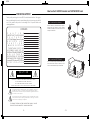
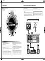
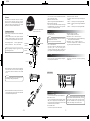
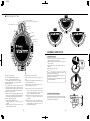
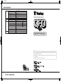
QFO-E
SPECIFICATION
TURNTABLE
TONEARM
MIXER
MOTOR
DIRECT DRIVE QUARTZ
STARTING UP TIME
0.5sec(33 1/3rpm)70°
STARTING TORQUE
2.7kg・cm
BRAKING SYSTEM
ELECTRONIC BRAKE
SPEED
33 1/3rpm,45rpm
PITCH
±60%
WOW & FLUTTER
0.07% W.R.M.S
TYPE
DYNAMIC BALANCE STRAIGHT TONEARM
STYLUS PRESSURE
ADJUSTMENT RANGE 0∼4.0g
INPUT
NOMINAL INPUT LEVEL
IMPEDANCE
LINE
-10dBv
10kΩ
NOMINAL OUTPUT LEVEL
IMPEDANCE
MASTER
-10dBv
220Ω
PHONES
58mW MAX(@47Ω)
≧8Ω
OUTPUT
OTHER
Creative Musical Interface
FREQUENCY RESPONSE
25Hz∼25kHz
CROSSTALK
≧100dB
THD
<0.01%
S/N RATIO
≧75dB
DIMENSIONS(W×H×D)
455×130×524(mm)
WEIGHT
7.0kg
OWNER'S MANUAL
NOTE
1.
VESTAX insulater is needed (not included) when the QFO is placed horizontaly to suppress
howling under high volume use.
2.
VESTAX QFO strap hook(not included) will be needed when playing the QFO strapped around
shoulder or hip.
※Attachment instructions are shown on page 16
Vestax Corporation
1
JUL.2004 QFOE○
QFO-E
How to attach VESTAX insulater and VESTAX QFO hook
CONGRATULATIONS!
Thank you for purchasing the Vestax QFO Creative Musical Interface. We suggest
that you read through this owner's manual thoroughly so that you may enjoy the full
use of this product safety and in the knowledge of all its special features and
suitablyapplications.
CONTENTS
C
A
U
T
I
O
N
IMPORTANT SAFEGUARDS
F
E
A
T
U
R
E
S
A.S.T.S(Anti Skipping Tone-arm System)
B E F O R E
U S E
F U N C T I O N S
M I X E R
S E C T I O N
TURNTABLE SECTION
ASSEMBLY AND SET-UP
INSTALLATION AND CONNECTION
A D J U S T M E N T
OPERATION OF RECORD
EXCHANGE THE FADER UNIT
How to attach VESTAX insulater and VESTAX QFO hook
S P E C I F I C A T I O N
2
3
4
5
5
6
6
8
9
11
12
13
14
15
16
How to attach insulater
When the machine is placed horizontaly to suppress
howling under high volume use, attach VESTAX
insulater(not included) on 4 sections of the bottom of
the body as shown below.
How to attach QFO hook
In use of the QFO strapped around shoulder or hip,
attach VESTAX QFO hook(not included) to the 2
sections of the bottom of the body as shown below.
CAUTION
RISK OF ELECTRIC SHOCK DO NOT OPEN
C A U Tl0 N :TO R ED U C E T H E R l S K O F E L E C T R l C S H O C K
D O N O T R EM O V E C O V E R ( O R B A C K )
N O U S ER - S ER V I C E A B L E P A R T S I N S I D E
R EFER S ER V lC I N G T0 Q U A L I F I E D S E R V l C E P E R S O N N E L
T he lig ht ning f la s h w it h a rr o w h e a d s y m b o l , w i th i n a n e q u i l a te r a l tr i a n g l e , i s
in t e n de d t o a le r t t he u s e r to th e p r e s e n c e o f u n i n s u l a te d “ d a n g er o u s v o l ta g e ”
w it hin t he p r o du ct 's e n clo s u r e th a t m a y b e o f s u f f i c i e n t m a g n i tu d e to c o n s i tu te a
r is k o f e le ct r ic s h o ck t o p e r s o n s .
T he e x cla ma t io n po int w it h i n a n e q u i l a te r a l tr i a n g l e i s i n te n d ed to a l e r t th e u s e r
t o t he p r e s e nce o f impo r t a n t o p e r a ti n g a n d m a i n te n a n c e ( s e r v i c i ng ) i n s tr u c ti o n s
in t h e lit e r a t ur e a cco mpa n y i n g th e a p p l i a n c e .
T0 REDUCE THE RISK 0F FIRE 0R ELECTRlC SHOCK,DO NOT
EXPOSE THIS APPLIANCE T0 RAIN 0R M0ISTURE.
-2-
-15 -
QFO-E
EXCHANGE THE FADER UNIT
①Remove the 4 screws which fix the fader unit, and
remove the fader unit from position in this unit.
②Raise fader unit and remove both the surface fader
panel and the buffer rubber below the panel.
③Carefully remove the multi-cable connector from the
fader unit.
④Remove the fader knobs.
⑤Remove the bracket which is screwed to fader volume
from the removed fader unit. (see the right picture) ⑥Fix the bracket to the new fader unit in the way of
reverse process.
⑦Attach multi-cable connector to new fader unit.
⑧Position the fader unit carefully and secure with screws.
FADER KNOB
FADER PANEL
BUFFER RUBER①
BRACKET
FADER VOLUME
CONNECTOR CABLE
BUFFER RUBER②
NOTE
The buffer rubber is very important part to avoid the
stylus skip. Be careful not to lose it when you change
fader unit. When you change to new fader unit,
please fix the buffer rubber properly.
BRACKET
FADER VOLUME
【Instructions for cross fader “CF-CPV” replacement】
①Unscrew the two screws on the
CF-PCV panel and volume as it is
shown below
②Set the change switch of the CFPCV to PMC
③Connect the QFO bracket to the
CF-PCV fader volume
NOTE
CF-PCV has to types of connectors
but connect it to the PMC connector
as shown below
PMC Connecter
Set this switch to "PMC"
-14 -
IMPORTANT SAFEGUARDS
READ BEFORE OPERATING EQUIPMENT
This product was designed and manufactured to meet strict quality and safety
standards. There are, however, some installation and operation precautions
which you should be particularly aware of.
1.Read instructions-All the safety and operating
instructions should be read before the appliance is
operated.
2.Retain instructions-The safety and operating
instructions should be retained for future reference.
3. Heed Warnings-All warnings on the appliance and
in the operating instructions should be adhered to.
4.Follow Instructions-All operating and use instructions
should be followed.
5.Cleaning-Unplug this product from the wall outlet
before cleaning. Do not use liquid cleaners or
aerosol cleaners. Use a damp cloth for cleaning.
6.Attachments-Do not use attachments not
recommended by the product manufacturer as they
may cause hazards.
7.Water and Moisture-Do not use this product near
water-for example, near a dath tub, wash bowl,
kitchen sink, or laundry tub, in a wet basement, or
near a swimming pool, and the like.
8.Accessories-Do not place this product on an
unstable cart, stand, tripod, or table. The product
may fall, causing serious injury to a child or adult,
and serious damage to the appliance. Use only with
a cart,. stand, tripod, bracket, or table recommended
by the manufacturer, or sold with product. Any
mounting of the appliance should follow the
manufacturer's instructions, and sholud use a
mounting accessory recommended by the
manufacturer.
9.Ventilation-Slots and openings in the cabinet are
provided for ventilation and to ensure reliable
operation of the product and to protect it from
overheating, and these openings must not be
blocked or covered. The openings should never be
blocked by placting the product on a bed, sofa, rug,
or other similar surface. This product should never
be placed near or over a radiator or heat register.
This product should not be placed in a built-in
installation such as a bookcase or rack unless
proper ventilation is provided or the manufacturer's
instructions have been adhered to.
10.Power sources-This product should be operated
only from the type of power source indicated on the
marking label. If you are not sure of the type of
power supply to your home, consult your appliance
dealer or local power company.
11. Grounding or Polarization-This product is equipped
with a polarized alternating-current line plug (a plug
having one blade wider than the other). This piug
will fit into the power outlet only one way. This is
safety feature. If you are unable to insert the plug
fully into the outlet, try reversing the plug. If this
should still fail to fit, contact your electrician to
replace your obsolete outlet. Do not defeat the
safety purpose of the polarized plug.
12.Power-Cord Protection-Power supply cords should
be routed so that they are not likely to be walked on
or pinched by intems placed upon or against them,
paying particular attention to cords at plugs,
convenience receptacles, and the point where they
exit from the appliance.
13.Protective Attachment Plug-The appliance is
equipped with an attachment plug having overload
protection. This is a safety feature. See Instruction
Manual for replacement or resetting of protective
device. If replacement of the plug is required, be
sure the service technician has used a replacement
plug specified by the manufacturer that has the
same overload protection as the original plug.
14.Lightning-For added protection for this product
during lightning storm, or when it is left unattended
and unused for long periods of time, unplug it from
the wall outlet. This will prevent damage to the
product due to lightning and power-line surges.
15.Overloading-Do not overload wall outlets and
extension cords as this can result in a risk of fire or
electric shock.
16.Object and Liquid Entry-Never push objects of any
kind into this product through openings as they may
touch dangerous voltage points or short-out parts
that could result in a fire or electric shock. Never
spill liquid of any kind on the product.
17. Servicing-Do not attempt to service product
yourself as opening or removing covers may expose
you to dangerrous voltage or other hazards. Refer
all servicing to qualified sersonnel.
18. Damage Requiring Service-Unplug this product
from the wall outlet and refer servicing to qualified
service personnel under the following conditions:
a. When the power-supply cord or plug is damage.
b. If liquid has been spilled or objects have fallen into
the product.
-3-
QFO-E
OPERATION OF RECORD
①Place a record on the slip mat.
c. If the product has been exposed to rain or water.
d. If the product dose not operate normally by
following the operating instructions. Adjust only
those controls that are coverd by the operating
instructions as an improper adjustment of other,
controls may result in damage and will often require
extensive work by a qualified technician to restore
the product to its normal operation.
e. If the product has been dropped or cabinet has
been damaged.
f. When the product exhibits a distinct change in
perfromance-this indicates need for service.
19.Replacement Parts-When replacement parts are
required, be sure the service technician has used
replacement parts specified by the manufacturer or
have the same characterristics as the original parts.
Unauthorized substitutions may result in fire, electric
shock or other hazards.
20. Safety Check-Upon completion of any service or
repairs to product, ask the service technician to
perfrom sefety checks to determine that the product
is in proper operating condition.
21.Carts and Stands-The appliance should be used
Stylus Pressure by
only with a cart stand that Dynamic
is recommended
Adjustment knob
manufacturer.
22.An appliance and cart combination should be
moved with care. Quick stops, excessive force, and
uneven surfaces may cause the appliance and cart
combination to overturn.
②Turn power switch to "ON" position.
③Remove stylus protector if applicable.
④Select the input select switch to "phono".
⑤Select appropriate rotation speed. (33/45rpm)
⑥Push Start/Stop Switch to start rotation.
⑦Carefully place tonearm on the record.
⑧Adjust the each level volume.
⑨Replace tonearm to rest position after play has finished.
⑩Press Start/Stop Switch to stop rotation.
⑪Turn power switch to "OFF" position.
POWER SWITCH
R
OT
NIT C
O E
M EL
S
TRIM
MIN
M
PG
1
ER
M
ST
PG MA
DE
MO
CH
PIT
R
2
POWER
0
9
L 90 180
MIN
MAX
HI
MEMO
If you select "PHONO" for both program channels,
reproduced sound of record is
assigned to each channel. For example, if you squeeze
EQ of PGM1 and fix EQ of PGM
at the center level and at the same time using Cross
Fader with Input Level Volume of
both program channels risen, it enables the
mixing/changing of EQ adjusted reproduced
sound and non-adjusted reproduced sound.
EQ
-12dB
+12dB
LOW
図a
M
ST
PG MA
MIN
MAX
HI
EQ
-12dB
+12dB
LOW
Input select switch
to "PHONO"
NOTE
If the power switch is turned off without pressing the
START/STOP Switch, the electric brake will not function.
-24dB
+12dB
PHONO
LINE 1
PGM 1
LEVEL
10
9
8
7
6
5
4
3
2
1
0
FEATURES
PLAYING EP RECORDS
Loosen
●The heart of
machine, motor has proven its high stability and reliability in Vestax PDX-2000series. The
motor is our original high torque direct drive.
●Vestax PMC-05 PROs reliable circuitry is loaded
Slide and adjust
Tighten
●Spin slide pitch controller placed around the platter(MAX ±60%).Linking pitch moves and scratches are
possible.
tTghten
Loose
-4-
-13-
図b
E
RS
VE
RE
●The “Dynamic Balance A.S.T.S.” allows the needle to trace the groove at any angle with no skipping or
tracing error.
Fit the EP adaptor over the center spindle and follow the
same playing instructions as written above.
CK
LO
TZ
AR
QU
●This is the very first model designed by Q-BERT which has DJ Mixer and Turntable in one united body.
MASTER
LEVEL
MAX
QFO-E
ADJUSTMENT
A.S.T.S(Anti Skipping Tone-arm System)
NOTE
Be careful not to touch your finger to the stylus tip
during the adjustment.
A.S.T.S(Anti Skipping Tone-arm System) has been developed with years of
experience and a number of trials, searching for the innovative tone-arm for
professional DJ's.This system breaks all of the historic common sense, achieving
its non skipping performance in hard scratching. A.S.T.S consists of two
inventions, short/straight arm and TH (Tracing Hold) balance system.
Adjustment of Horizontal Zero(0) Balance
①Install the cartridge, headshell and balance weight to the
tonearm.
②Adjust the dynamic stylus pressure knob ob the tonearm
to Zero.
③Carefully release the tone arm from the tone arm clamp.
Dynamic Stylus Pressure
Adjustment knob
●TH balance system gives horizontal movement in addition to vertical. This movement gives much more stable
balance (vertical direction) to the needle. The combination of short / straight arm and TH balance system
gives the best stability to the needle, which enables anti-skipping in hard scratching.
●The brass arm with aluminum cover is used for A.S.T.S . This combination results in the best pick up
sensitivity as well as the best resistance to howling. This new tone-arm allowed A.S.T.S to increase the
resistance against the howling by over 50% compared to the normal aluminum arm.
④Turn the balance weight clockwise or counterclockwise
until balanced horizontally.
NOTE
In case the balanceweight is moved, do the adjustment
of horizontal zero balance again.
NORMAL TYPE TONE-ARM
F Tracking force
F1 Inside force
F2 Vertical force
a)When the balance weight and cartridge are
balanced, the tone arm is held horizontal.
F1
⑤Return the tonearm to the armrest.
⑥Loosen the dynamic Stylus pressure adjustment knob
and pull it to the position with appropriate needle
pressure, tighten the knob.
b)Excessive forward advancement of the balance
weight causes the cartridge side to be lowered.
A. S. T. S
F
Needle trace
F2
F(Tracking force)generates inside force.
NOTE
Exceeding stylus pressure recommendations may
couse skipping and/ or reduce stylus life.
Needle trace
F
No inside force is generated.
c)Excessive backward retreatment of the balance
weight causes the cartridge side to be raised.
Loosen
BEFORE USE
Slide and adjust
Tighten
Adjustment of Tone-arm Height
In case of the height of Tone-arm is needed for
adjustment, it is possible to adjust the height by loosening
the Tone-arm Height Fixed Screw. The adjustment range
is 9mm at the maximum. In case of 16mm cartridge height
→ Adjustment of tone-arm height do not need. In case of
25mm cartridge height → Adjustment of tone-arm height
need to set
9mm(MAX).
Screw Driver
tTghten
Tighten
Parts and accessories
Before use, please check that you have all parts.
Main unit
Platter
Split mat
Head shell
Balance weight
※Accesories accompanying this booklet.
Shell weight
EP adapter
Platter screws
Screw driver for platter screw
Owner's manual
COIN
Loose
NOTE
Be sure to tighten the Tonearm Height Screw well. The
stylus may jump/skip if the height setting is not secured.
Arm Height
Adjustment Screw
-12-
-5-
QFO-E
FUNCTIONS
INSTALLATION AND CONNECTION
■MIXER SECTION
Player Installation
TOP PANEL
・ Do not place the unit where it is exposed to direct sun
light, high temperature of humidity to prevent possible
troubles.
・ Place the unit in a stable and horizontal position, where
there is little or no vibration.
・ocate the unit as far away from the speakers as possible
and isolate the unit from sound radiation from them.
・If the unit is placed too close to the radio, interference to
AM/FM reception may result
10
(Side)
1
POWER
9
DE
MO
CH
PIT
2
90
R
OT
NIT C
O E
M EL
S
TRIM
3
MIN
M
PG
1
ER
M
ST
PG MA
2
90
8
R
2
MA
L 0
18
MIN
ST
ER
MAX
OF
MU
ON
MAX
MIN
3
MAX
HI
EQ
+12dB
-12dB
LOW
+12dB
LOW
+12dB
-24dB
PHONO
4
Connect to line input/AUX input on your mixer/pre-amp.
+12dB
4
PHONO
LINE 1
LINE 2
PGM 1
LEVEL
5
10
9
8
7
9
8
7
6
5
6
5
4
3
4
3
2
2
1
0
1
0
5
QU
AR
TZ
LO
CK
CK
LO
TZ
AR
QU
ER
SE
15(Bottom)
E
RS
RE
V
VE
RE
/4
rp
m
33
m
33
rp
/4
5
5
15
Connection To Input
PGM 2
LEVEL
10
(Bottom)
NOTE
This unit has been manufactured to fit strict quality and
safety standards. PLEASE ENSURE that you use the
correct power supply as shown on the rear panel of
this device. FAILURE to do so many result in shock
and/or serious damage to this unit and/or users.
TRIM
EQ
-24dB
Connect the AC power cord to suitable outlet.
TE
F
HI
-12dB
7
MASTER
LEVEL
Power Connection
ST
AR
T/
T
AR
ST
ST
OP
90L
+60
13
(Side)
180
- 60
Hook(sold seperate)
90R
PITCH
0
P
TO
/S
+60
0
PHONES
PHONES
LEVEL
PHONES
14(Side)
C.F. CURVE
12
LINE2
LINE1
QFO REAR PANEL
(Side)
6
11
MODEL NO. QFO
16(Bottom)
(Side)
L
100V 50/60Hz 15W
MADE IN CHINA
SERIAL NO.
R
LINE 2
TOP
qPOWER INDICATOR
Lights up when the POWER SWITCH is on.
wTRIM VOLUME
Adjusts the input level of each channel. Set INPUT
FADER to 7-8 position; adjust the TRIM so that the
sufficient signal is fed without distortion.
eEQ VOLUME
Adjusts the HI and LOW frequencies for each PGM
hannel.
rPHONO/LINE SELECT SWITCH
Used to select the input (LINE or PHONO) to be sent to
each PGM channel. When it is selected "PHONO", it is
assigned the signal of record of this unitIt can also be
used for TRANSFORMER SCRATCH. Its operational
direction is selectable. You can change the direction by
removing the top panel. If you select "PHONO" for both
PGM1 and 2, reproduced sound of record is assigned to
each program channel.
tINPUT FADER (PGM1/PGM2)
Used to adjust input level of each PGM channel. This is
a detachable fader for ease of replacement. Replace
with IF-Q when it is worn out. Please see the "EXCHANGE
THE FADER UNIT" section of this manual.
yCROSS FADER
When the input level of PGM1 and PGM2 are properly
set, PGM1 will be heard with the crossfader set to the
left side. PGM2 will be heard with the cross fader set to
the right side. When the crossfader is set in the center,
both programs will be heard. This is detachable fader
for the ease of replacement with "CF-PCV" when it is
-6-
MASTER
OUT
LINE 1
MASTER OUT
LINE IN
-11-
QFO-E
Place the slip mat on the platter. Then place a record on
top of the slip mat. By using a slip mat, it becomes
possible to stop a record board by hand during rotation of
a platter or to make it reverse. Moreover, if an optional
slip-sheet is set and used, it will take effect more.
Top:Record disc side(Printed side)
Bottom:Slip surface side
Cartridge Installation
(1)Make sure that you follow the instructions included with
your cartridge.
(2)Connect the lead wires to the respective terminals.
Industry standard cartridges come with color-coded
wires. Make sure that you match these colors correctly.
SIDE
!0POWER SWITCH
Use to turn power on.
NOTE
This switch should be turned on after you have turned
off all input devices and before
you turn on any devices attached to output.
NUT
Red (R+) Right Channel+ Green (R-) Right Channel White (L-) Left Channel+ Blue (L-) Left Channel NOTE
If using a lightweight cartridge, we suggest the use of
the shell weight enclosed.
oMONITOR SELECT SWITCH
This switch is used to select the way of monitoring from
following.
PGM1・・・・・ It allows you to hear input signal of PGM1.
MASTER ・・ It allows you to hear the signal of MASTER
OUT.
PGM2・・・・・ It allows you to hear input signal of PGM2.
worn out. Please see the "EXCHANGE THE FADER
UNIT" section of this manual.
uMASTER LEVELVOLUME
Adjusts the signal level outputs from MASTER OUT.
iMASTER MUTE SWITCH
This is the switch which mutes the output sound signal
from MASTER OUT jack of the rear panel. If you turn
the switch on, the output will be muted.
Slip mat
HEADSHELL
(OPTION)
LEAD WIRE
SHELL WEIGHT
(OPTION)
CARTRIDGE
!2PHONES LEVEL VOLUME
Adjusts the headphone monitor level.
!3PHONES2 JACK -MINI JACK(φ3.5)
Connect the headphones with a 1/8" mini headphone plug.
(the impedance of 8ohm to 600ohm)
!4PHONES1 JACK -PHONE JACK(φ6.3)
Connect the headphones with a standard 1/4" stereo
plug. (the impedance of 8ohm to 600ohm)
!1C.F. CURVE SWITCH
Select the cross fader curve. When this switch is slide to
right side it gives a steep cross fader good for
scratching and cutting. When sliding to the left side it
gives a gentle cross fader good for long running mixes.
BOTTOM
!5I.F. REVERSE SWITCH
Reverses the action of the input fader by marking the
zero point top instead of bottom.
STYLUS
!6C.F. REVERSE SWITCH
Reverses the action of the cross fader by switching
PGM1 and 2.
SCREW
(3)The overhang of your cartridge needs to be adjusted to
best suit the A.S.T.S tone arm. For best tracking and
stylus pressure a distance of 50mm (as shown) should
be set.
REAR PANEL
MODEL NO. QFO
NOTE
To avoid premature damage to the stylus take care to
avoid touching it during any adjustment(s).
L
100V 50/60Hz 15W
MADE IN CHINA
SERIAL NO.
R
50mm
(4)Insert the head shell into the front part of the tone arm.
Turn the looking ring in the direction shown below until
the head shell is firmly fixed in place.
-10-
LINE 2
MASTER
OUT
LINE 1
18
17
18
19
REAR PANEL
!7MASTER OUT JACK
Connect to the line/AUX input of power amplifier/mixer.
!8LINE INPUT JACK
Connect the equipment with line level output (-10dB or
0dB), such as CD players, tape decks, DATs, MDs, etc.
The signal from line level equipment is fed to the PGM
channels when Line input is selected.
!9AC POWER CODE
Connect the AC power cord to suitable outlet.
NOTE
This unit has been manufactured to fit strict quality and
safety standards. PLEASE ENSURE that you use the
correct power supply as shown on the rear panel of
this device. FAILURE to do so many result in shock
and/or serious damage to this unit and/or users.
-7-
QFO-E
■TURNTABLE SECTION
180
+60%
-60%
+60
0%
fr
90L
Tone Arm
25
TRIM
Headshell
MAX
+12dB
PGM 2
LEVEL
10
9
8
7
8
7
6
6
5
4
5
4
3
3
2
1
2
1
0
0
o +6
-60%
0%
s
It doe
sl
n ot
id e
to
0%
to
0%
e
PGM 1
LEVEL
10
9
0%
li d
LINE 2
0%
om
-6 0
%t
fr
LINE 1
Platter(Option)
ts
+12dB
PHONO
bly
-24dB
PHONO
ri a
Slip Mat(Option)
LOW
no
-12dB
s va
+12dB
LOW
+12dB
es
HI
EQ
%
MIN
EQ
-12dB
+60%
-60%
MU
TE
HI
-24dB
-60%
+60%
90R
It do
MAX
Lock Ring
m
+60
ON
ro
-
-6
0%
in t
his r
-60%
ang
Slides
ab
v a ri
ly f
ro
m
ASSEMBLY AND SET-UP
LO
QU
AR
TZ
LO
CK
TZ
AR
QU
RE
RS
RE
V
VE
E
rp
33
m
rp
/4
5
5
/4
21
22
m
33
22
23
ER
SE
CK
23
ST
AR
T/
T
AR
ST
ST
OP
20
21
P
TO
/S
20
90L
+60
90R
PITCH
0
180
- 60
0
+60
PHONES
PHONES
LEVEL
PHONES
C.F. CURVE
24
@0START/STOP SWITCH
It is started/stopped the platter every push.
@133/45(33/45rpm)SELECT SWITCH
Select the playing speed to either 33 1/3 or 45rpm.
When the indicator LED is lit, it is selected 33rpm.
@2REVERSE SWITCH
When pushed, this switch will instantly reverse the
playing direction of the platter. In reverse mode, an
indicator LED will be on. When the unit is first turned on,
the platter is set to spin in the normal forward direction.
@3QUARTZ LOCK SWITCH
When this switch is on, the indicator LED is lit.When this
switch is on, the speed will become pre-determined one
even the Pitch Control Volume not in the 0% position.
@4PITCH CONTROL VOLUME
This volume is for adjusting the pitch.
1.When the Quartz Lock is off, the pitch can be
adjusted.
2.When moving the Pitch Control Volume, you can
adjust the revolutions by ±60%.
@5PITCH MODE SELECT SWITCH
Select the mode of the pitch control. The mode is as
below.
1.When pressing the quartz lock button, quartz lock is
off.(the indicator lamp is off)
2.When moving the Pitch Control Volume, you can
adjust the revolutions as bellows.
90L:The position of 9 o'clock is +60% and that of 6
o'clock is -60%. It changes from +60% to -60%
counter clockwise. Between 6 o'clock and 3
o'clock, it is fixed at -60% and unchanged.
180:The position of 3 o'clock is +60%, 6 o'clock is -60%
and 9 o'clock is +60%. The rotation pace is
changeable.
90R:The position of 3 o'clock is +60% and that of 6
o'clock is -60%. It changes from +60% to -60%
clockwise. Between 6 o'clock and 9 o'clock, it is
fixed at -60% and unchanged.
-8-
Turntable Assembly
(1)Place the platter on the center spindle. The platter will
adjust itself to best fit over the spindle.
(2)Adjust the positioning of a platter so that a screw goes
into a screw holes.
(3)Tighten screws using a driver and fix a platter and a
main unit.
(4)Place the slip mat on the platter.
DRIVER
NOTE
In case of an assembly, be careful so that a main unit
and a platter do not collide strongly.
If the player is operated without fixing the screws, the
platter may not rotate properly.
Do not plug into a power outlet until this unit is fully
assembled and adjusted.
Installing the Balance Weight
From the backend of the tone arm (towards the rear panel)
place the balance weight onto the shaft and turn counter
clockwise. (Refer to the illustration)
-9-
to
OF
F
ly f
0%
MA
ST
ER
MAX
ab
v a ri
-6
MIN
rang
MO
0R
9
L 90 180
Slides
this
CH
Slide
MIN
2
0%
in
TRIM
M
PG
1
ER
M
ST
PG M A
-60%
%
PIT
R
OT
NIT C
O E
M EL
S
MASTER
LEVEL
o +6
60
POWER
DE
0%
bly
0%
om
-6 0
%t
-6
ri a
Arm Rest
to
s va
Tone-Arm Height Fixed Screw
%
Slide
Balance Weight(Option)
Dynamic Stylus Pressure Adjustment Knob