1
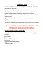
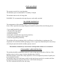
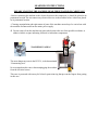
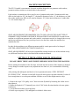
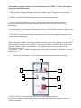
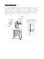
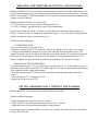
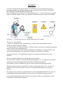
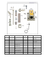
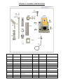
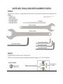
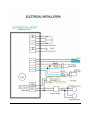
Model PG-239 Electronic Automatic Grommet Operating Manual (800) 624-2408 (530) 626-9386 Fax (530) 626-5144 6686 Merchandise Way Diamond Springs, Ca 95619 www.sineqco.com INTRODUCTION MACHINE MODEL PG-239 AUTOMATIC WITH TWO DEPOSITS TO PLACE GROMMET AND WASHER. The object of this machine is to place grommet and washer in canvas, curtains, or any other material that requires this kind of reinforcement, can be used to place the grommet and washer, only the grommet or to simply perforate the material. - Lack of familiarity with the machine usually leads the operator to elemental doubts about its operation. - Read this manual carefully to securely operate and optimize the machine’s capability. - We urge you to follow this advice, and appreciate your trust at the moment of buying the machine. SINCLAIR EQUIPMENT ASSUMES NO RESPONSIBILITY ABOUT THE INCORRECT USE OF THIS MANUAL OR INCORRECT INTERPRETATION OF THE INSTRUCTIONS PROVIDED. MACHINE IDENTIFICATION AND PLATES This machine includes an aluminum plate attached with four rivets indicating the following: Factory Name Manufacturing Year Model and Manufacturing number Power in kw Air pressure (on pneumatic machines) CE Mark Weight in Kilograms DESCRIPTION OF THE MACHINE AND ITS OPERATION. MACHINE MODEL PG-239. AUTOMATIC ELECTRONIC WITH TWO HOPPER BOXES FOR PLACING GROMMET AND WASHER. The machine consists of a metallic stand with a wood base on which the machine is mounted. The pedal and the electronic equipment that control the machine are located in the stand. The head of the machine is comprised of a machine housing and two raceways (one on each side). The moving parts in the machine are located inside the housing, such as: the main motor, axles, eccentrics, bearings, etc. The grommets and the washers use the two raceways to descend. The PG-239 model is designed to automatically place the grommets with washers, the grommet without the washer, or to punch holes in the material. Facing the machine, the grommets are placed in the left hopper box “ A1 ” and the washers in hopper box “ B1 ”. Both hopper boxes are rotated by individual 24V motors. The grommets that descend along the left raceway “ A2 ” are held by a small finger, which stops them from falling. Lower horizontal guides hold the washers descending along the right raceway “ B2 ”. The machine is controlled by an electronic unit designated IMO V3 “ C ”, located inside the mounting stand. The IMO V3 unit receives an electric signal through pedal “ D ” that allows the main motor “ E ”located behind the head, to quickly rotate and haul the flywheel (part no. 274) with a belt making a 360° rotation causing the motor to stop sharply. The flywheel (part no. 274) has a main shaft (part no. 207) that joins the plunger with the other moving parts. By rotating 360°, it exerts pressure on the driving stem and therefore the grommeting action is completed. The top set spindle (part no. 218) inside the top set (part no.217) inserts itself inside the grommet and pulls it down from raceway “ A2 ”. At the same time the slide (part no. 297) pushes the washer from the slide track and places it exactly on top of the bottom set (part no. 219). A1 B1 A2 E B2 C D INSTALLATION The operator can work in a seated position. The minimum space recommended is 7ft width by 5ft depth. The machine comes with a 6 ft long cable. WARNING: We recommend not having the power cord totally stretched. MACHINE HANDLING The transportation of this machine requires a series of operations. Some of these operations may imply dangerous situations so please follow the following advise: - Never stand beneath the cargo. - Always lift the cargo gently. - Avoid balancing the cargo. - No brisk movements. - Do not place yourself in the cargo moving trajectory. - Use the correct equipment to move cargos. - Check this equipment periodically. The machine will carry packaging which is sufficient to avoid knocking or scraping any of its components. We advise that wooden packaging, in box or cage form, should always be used, always with adequate protection and the machine properly secured. The machines should always travel in the vertical position and never be overturned. UNLOADING AND LEVELLING The machine should be unloaded by means of a crane, using ropes at both sides of the box. If the machine comes in a box or cage, it can be unloaded using a fork lift. When the machine is on the floor, totally unpacked, it is to be transported by means of a pallet jack to its permanent location. The machine comes out of the factory totally leveled, and does not need to be secured to the floor. It incorporates rubber leg tips for it not to move with vibration during use. The floor underneath should be firm and strong. LEARNING INSTRUCTIONS !BEFORE STARTING THE MACHINE, READ THESE WARNINGS CAREFULLY! - Before connecting the machine to the electrical outlet or the compressor, it should be placed in its permanent location. Do not connect any electrical devices to the machine before it has been placed in its permanent location. - Cleaning, manipulation and replacement of parts of the machine must always be carried out with the machine disconnected from the mains power supply. Do not remove from the machine any parts which protect the user from possible accidents, or adhesive labels or signs indicating electrical or hazardous components. ! DANGEROUS AREA ! The most dangerous zone in the PG-239, is the denominated “Grommeting area”. Never manipulate this zone without unplugging the machine from the electrical source. This zone is protected with an acrylic lid and a protection ring that prevent the fingers from getting in this area. MACHINE DESCRIPTION The PG-239 model is an automatic electronic machine designed to set grommets with washers, grommets without washers or to make holes in the material. Each machine is manufactured for a specific size of grommet and washer. Grommet models may differ in: the head size “B”, the length “C”, the interior diameter of tube “A”, the thickness, etc; and the washer models may differ in: the exterior diameter “B”, & the interior diameter of washer hole “A”, the washer shape, etc. SINCLAIR EQUIPMENT RECOMMENDS YOU TO USE ALWAYS THE SAME TYPE OF GROMMET AND WASHER FOR WHICH THE MACHINE WAS DESIGNED. In order for the machine to set different grommet and washer models, certain parts need to be changed (the raceway and the top and bottom sets); but you always have to use the same washer the machine was manufactured for. In order for the machine to set different grommet models, certain parts need to be changed. (SEE THE ADJUSTMENTS SECTION OF MANUAL.) SINCLAIR EQUIPMENT will accept no responsibility arising from the use of this machine in any way different from that which is described in this instruction manual. SETTING UP THE MACHINE FOR ITS OPERATION PLEASE VERIFY THESE ADJUSTMENTS BEFORE CONNECTING THE MACHINE. Before starting the machine for the first time, and each time the location of the machine is changed, or any changes are made in parts or any adjustments are done to it, we recommend the following steps: After placing and making the machine level in its permanent location “STILL WITHOUT PLUGGING IT IN”, lubricate it with SAE 40 type oil in the grease cups and red marks. Let the oil have enough time to cover the parts and then clean the excess oil that might remain or drip. 1- Remove the cap nº 158 “pulley cover” that covers the flywheel by loosening the 4 allen screws that tighten it. 2- Rotate the flywheel nº 274 manually one cicle of 360º in the direction that the red arrow points (clockwise). 3- Verify that the machine is moving freely. 4- Put the cap on again (nº 158) and tighten it with the 4 allen screws. The machine is equipped in the base with an electronic device “IMO V3” and a control panel showing the following features: 1- Main Switch: connects or disconnects all of the machine systems. When the switch is pushed towards the symbol “I”, the led will light showing that the machine is “ON”. 2- Marcha: red led shows that the machine is connected and in stand-by mode. 3- Status: green led will light every time we press the pedal indicating that the machine is in operation. If illuminated in a pulsating fashion, it indicates failure, disconnect the machine immediately. 4- Green pointer or switch: turns the lighted pointer on or off. Only in those machines equipped with this device (optional). 5- Red switch or feeder: connects or disconnects the two 24V motors that make the grommets and washers rotate in the deposits. 6- Washer detector: detects the flow of washers in the railing. When selected with the position “0”, it does not detect the washers in the railing, and the machine may place only grommets or punch holes. When pulsated to the outermost position “1”, it detects the washers, and will not allow to place the grommet without a washer or to punch holes. The railing must have at least 8 washers for this feature to work properly. The position" 2" and" 3" doesn't have application in this model of machine, we therefore will always indicate" 0" or "1”. 7- 6 Amp fuse. Fuse holder. Uses a 6 amp fuse to protect the machine from high voltage. 4 6 5 2 3 7 1 The IMO V3 device is responsible for the electrical working of the machine. It must not be opened or manipulated except by an authorized technician, or with the consent of Sinclair Equipment. OTHER MACHINE USES For setting grommets without the washers, or punching out holes, all the washers must be removed from the hopper box and the guides, the grommet raceway must be moved back and the top and bottom dies (parts nº 217, 218, 219 and 229) must be replaced by other parts specific to this task. THIS MACHINE MUST NOT BE USED FOR ANY FUNCTION OTHER THAN THAT FOR WHICH IT WAS ORIGINALLY DESIGNED AND WHICH IS SPECIFIED IN THIS INSTRUCTION MANUAL: THE AUTOMATIC SETTING OF GROMMETS WITHOUT WASHERS, GROMMETS ONLY, OR HOLE PUNCHING ONLY. ADJUSTMENTS Each PG-239 machine places a grommet model and a washer, although other grommet dimensions may be placed by replacing the corresponding parts. This replacement is quick and simple. In order to fix a different grommet model a whole new raceway is needed together with the appropriate set of dies. With the machine unplugged: 1- Remove the stripper plate spring nº 237 from the raceway spring nut nº 238 which holds it in place. 2- Loosen both mounting screws nº 244 which are holding the front hopper box mounting bracket nº 240. 3- Use both hands for holding the grommet hopper box housing nº 242 and the grommet hopper box bottom plate nº 241and begin to push upwards (with slight clockwise rotations) in order to remove the whole raceway from the front hopper box mounting bracket nº 240. The whole set of dies or some of its parts (part nº 217, 218, 219 y 229) will have to be replaced according to the different grommet models. The dealer that sold you this machine or directly Sinclair will let you know about the parts that should be replaced. If no part of the set of dies needs to be replaced, continue at point 8. Changing the whole set of dies: 4- Pull upwardsthe ring compensator nº 233C by moving the compensator base latch nº 196 that holds it. 5- Unscrew the top die nº 217, remove the top set spindle nº 218 and the top set spindle spring nº 229 , which are inside the top die. Unscrew the bottom die nº 219. 6- Replace the set of dies corresponding to the new grommet size, in the same order in which the other parts were removed. Firstly the top die nº 217 with the top set spindle nº 218 and the top set spindle spring nº 229 and then remove the bottom die nº 219. 7- Replace the ring compensator nº 233C around the bottom die nº 219, fit the compensator base latch nº 196 into the ring compensator groove nº 233C in order to hold it in place. Before starting the machine, it is necessary to adjust the tightness of your setting (Point 4.2. Adjusting the tightness of setting, change of dies; page 12). 8- Fit the new grommet raceway into the front hopper box mounting bracket nº 240 while manually rotating it back and forth, so that the driving stem nº 243 which is in the lower part, gets into the hopper box motor spin axis nº 239. 9- Tighten both 6 allen screws nº 244 for holding the part nº 240 , 10- Hold the stripper plate spring nº 237, which is held in place by the raceway spring nut nº 238. 11- The lower part of the raceway where the grommet you are going to set is placed, must be on the same vertical line as the spindle nº 218 so the spindle can take the grommet while coming down, 12- Adjust the tightness of setting (Point 4.2. Adjust the tightness of setting and changing dies). Remember you have to keep using the same washer model, you must not change it. ADJUSTING THE TIGHTNESS OF SETTING, CHANGING DIES Machine model PG-239 can set grommets in different types of material of different thicknesses. For a perfect grommeting action you can adjust the pressure that the dies put on the grommets. Each time the dies are changed, or a different material is used, it may be necessary to adjust the machine so that a proper setting is achieved. Machine model PG-239 has two vertical axles: - Nº 230 “Driving stem” that governs the cutting pressure, and, - Nº 215CA “Plunger” that governs the pressure of the grommeting. If you want to change the whole set of dies, you must follow the instructions from number 4 to number 7 shown at point 4.1.Change of grommet model; page 11. You must always change the dies with the machine disconnected from power source. With the machine unplugged. CUTTING PRESSURE: - Remove the flywheel cover part nº 158A - Manually rotate flywheel nº 274 (clockwise) until top set spindle nº 218, is in its lowest point - Unscrew nut that holds the bottom die in place, then rotate the bottom die holder part nº 220 until the bottom die part nº 219 barely touches the top set spindle part nº 218. Secure the bottom die holder part nº 220 through nut. The pressure of the spindle nº 218 against the bottom die nº 219 must be minimum, the pressure which is sufficient for punching a hole on a piece of paper. PRESSURE OF THE GROMMETING: - By unscrewing nut part nº 216 you will be able to turn the top set nº 217 to the right or left, until the distance between the bottom die nº 219 and the top die nº 217 equals approximately the thickness of the material used for setting the grommets, - Manually rotate flywheel nº 274 (clockwise) and check weather the adjustment of the dies is correct, - Secure the top set nº 217 through nut nº 216 - Replace the flywheel cover nº 158 SETTING GROMMETS ONLY, WITHOUT THE WASHERS Machine model PG-239 can also place grommets without the washers. With the machine unplugged: - Empty the hopper box and the raceway of washers, - On the “IMO V3” turn the washer detection switch to the “0” position. - Adjust the pressure of the grommeting and the cutting pressure For placing grommets without washers, we advice you to replace the bottom die #219 with another one specific to this task. PERFORATING ONLY If what you want is simply to make perforations in the material, you must place a new complete set of dies and make the following adjustments: With the machine disconnected from the power source: - Empty both the deposits and railings of any grommets and washers, - Move the grommet railing to the left and secure it with a small puncher to the front raceway bracket part nº 272 , - Next place the new complete set of dies and adjust the machine’s pressure. - In the control panel “IMO V3” the washer detector switch must be set to the “0” position. PLACEMENT LASER LIGHT (OPTIONAL ACCESSORIES) - Your machine has an optional laser light that emits a red laser beam that can help with the placement of the grommet and washer. - The machine includes a switch for this device, in the “IMO V3”. For connecting the switch see Electric installation. Note: Although the light power of this laser is very small. DO NOT SHINE THIS LIGHT DIRECTLY IN ANYONE’S EYES SINCE IT COULD BE HARMFUL. KEEP IT AWAY FROM CHILDREN. - For small grommets and washers, the machine may come with a little air pipe attached to the washer raceway, which blows the washer down onto their right position, by means of an air compressor. - For placing grommets and washers in materials such as: canvas, sailcloth, etc, a small metallic tray may be attached to the machine, in order to be used as a base for the material. - If you wish to know the amount of grommets and washers that you set each day, you can use a grommet and washer meter. - The back side of the grommet may have two shapes after having been placed in the material: 1) ring shaped grommeting, 2) star-flower shaped grommeting, depending on the kind of bottom die that you use: Ask for the flower-shaped or ring-shaped bottom die nº 219 according to the kind of grommeting that you wish to obtain. Due to differences in the tension of different supply systems, the top-set spindle stop-position nº 218 may not be correct, and the spindle stops at a point lower than normal. If you change the position of the detector screw nº 171 by screwing it into another hole (generally the one next to it) of the flywheel nº 274, we will be able to stop the top set spindle nº 218 in another position. The correct position is as high as possible. MAINTENANCE MECHANICAL PART OF THE MACHINE: For an optimal operation of the machine, it is recommended that you keep some parts clean and always lubricated. The cleaning should ALWAYS be done with the machine disconnected from the electrical power source and the compressor. The pedal we press to operate the machine should always be clean and clear of any debris that could prevent its normal operation. The exterior of the machine should be cleaned with a rag that will not leave threads, so that the threads can not be stuck to the machine. The head of the machine has exterior grease cups. You must use a manual pressure oil can to inject oil (the oil type to be used should be “SAE 40”) into the grease cups two or three times a week. We recommend to do this at the end of the journey, and clean up the possible excess oil the next day. During the first month of operation it must be done twice per week. After the first month it only needs to be done once a week. If the machine is going to go for a long period of time without use, it will be necessary to do a general cleaning, and greasing in the indicated spots, disconnecting it from the compressor or from the power source (if it has any electrical devices), and then cover it so that it is protected from the dust and/or humidity. ELECTRICAL PART OF THE MACHINE: The electrical part of the machine the IMO V3 is clearly marked with a yellow triangle and does not need any type of maintenance. Do not open unless directed to do so by Sinclair. The electrical parts of the machine: motors, cables, etc, come completely sealed and secured through nuts. The electrical parts need no maintenance, do not open or manipulate them. Parts nº 149 flywheel optical detector and nº 338 optical washer detector, should be kept clean, and to achieve this, they should be wiped with a dry cloth. If an optional laser light nº 155 has been installed, it needs no cleaning or maintenance, and remember that you must never shine it directly in anybody’s eyes, since it could be harmful. Both the main motor and the two hopper box motors are totally sealed and do not require any maintenance. TROUBLESHOOTING SECURITY As we have indicated in the manual, the PG-239 machine has a series of protection devices to prevent the operator from getting his fingers caught or any other kind of accident. PLEASE DO NOT REMOVE THESE PROTECTION DEVICES. The most dangerous area in the PG-239 is the grommeting area “C” where the operator may get his fingers or his hands caught. In order to prevent this, some protection devices have been installed: In figure 4 “C” we indicate the area we consider dangerous for the operator. This area “C” is protected by: - A part #167 transparent acrylic shield that allows vision but does not permit the worker to introduce his hands, indicated in figure 4. - A ring guard part #165 indicated in figure 7, that prevents the worker from accidentally introducing fingers or hands in the grommeting area. - The waste material pipe #350 is used for absorbing the remaining pieces of material that are left after the grommeting action. This pipe allows the operator to work more comfortably. These protection devices are tightly held through screws, that prevent them from becoming detached. All areas considered dangerous are marked and securely enclosed. The sticker shown in figure 5 warns you that the grommeting area "C" is a dangerous area, and the machine must always be unplugged before making any adjustments in that area. All mechanical, electric and pneumatic parts are securely enclosed and tightly screwed up. When the machine includes an optional device such as a laser pointer part #155C, you must not shine this pointer directly in anyone’s eyes since it could be harmful, and keep it away from children. We strongly warn you that for any adjustment or any other manipulation that needs to be done, the machine must be disconnected from the electrical power source and the compressor air inlet. For any problem that may arise and can not be solved, please call the nearest distributor or get in contact directly with Sinclair Equipment. Schematic # Part # E 113 114 115 149 153 154 PGR239E PGR239113 PGR239114 PGR239115 PGR239149 PGR239153 PGR239154 155 PGR239155 155c 156 157 158 158a PGR239155C PGR239156 PGR239157 PGR239158 PGR239158A 158b PGR239158B 160 PGR239160 Description Schematic # Part # Description Electronic Device IMO V3 Threaded Pin Nut Screw Flywheel Detector Laser Pointer Bracket Laser Pointer Threaded Support Laser Pointer 171 173 174 175 200 203 204 PGR239171 PGR239173 PGR239174 PGR239175 PGR239200 PGR239203 PGR239204 206 PGR239206 Laser Pointer Set Flywheel Detector Bracket Motor Cover Flywheel Cover Upper Part of Flywheel Cover Bottom Part Of Flywheel Cover Main Motor 274 325 339 341 344 PGR239274 PGR239325 PGR239339 PGR239341 PGR239344 Flywheel Detector Screw Bracket Magnet 7mm Part to fix with magnet Housing For Machine Cover for Plunger Unit Motor Mount Bolts, Nuts, & Washers (4) Machine House Bolts,Nuts, & Washers (4) Flywheel Electric Foot Pedal Screw For Plastic Cover Hinge Transformer Laser 347 PGR239347 Foot Pedal Protector 361 PGR239361 Drive Belt Schematic # 62 Part # Schematic # PGR239165 PGR239165H PGR239190 Plunger 227 PGR239227 183CA PGR239183CA 228 PGR239228 Raceway Cam Bracket 184CA PGR239184CA 230 PGR239230 Driving Stem 185CA PGR239185CA 231 PGR239231 202CA 215CA PGR239202CA PGR239215CA Driving Stem Guide Wheel Driving Stem Pin Screws to fix part #232 216 PGR239216 Upper part of washer compensator axle Lower part of washer compensator axle Washer forcompensator axle Plunger housing for 215 Upper guide collar washer compensator Lock Nut 222 PGR239222 Upper guide 224 225CA 232 M4X8 PGR239223 Description Plunger guide wheel for part #222 Screw for part 223 Bottom plunger ollar for part #184ca Raceway Cam 190 223 Part # Screw To Fix Plunger Hsng Ring Guard Ring Guard Bracket 165 165H PGR23962 Description PGR239224 PGR239225CA PGR239232 PGR239M4X8 WITHOUT WASHER COMPENSATOR Schematic # 62 Part # Schematic # Part # Description 224 PGR239224 Screw for part 223 PGR239165 PGR239165H Screw To Fix Plunger Hsng Ring Guard Ring Guard Bracket 225 226 PGR239225 PGR239226 190 PGR239190 Plunger 227 PGR239227 Bottom Plunger Collar Bottom Plunger Guide Pin Raceway Cam 202 215 216 PGR239202 PGR239215 PGR239216 Plunger Housing Upper Guide Collar Lock Nut 228 230 231 PGR239228 PGR239230 PGR239231 222 223 PGR239222 PGR239223 Upper Guide Plunger guide wheel for part #222 165 165H PGR23962 Description 232 M4X8 PGR239232 PGR239M4X8 Raceway Cam Bracket Driving Stem Driving Stem Guide Wheel Driving Stem Pin Screws to fix part #232 Schematic # Part # 72 201 207 208 209 210 211 212 213 214 275 276 277 278 PGR23972 PGR239201 PGR239207 PGR239208 PGR239209 PGR239210 PGR239211 PGR239212 PGR239213 PGR239214 PGR239275 PGR239276 PGR239277 PGR239278 Description Screw for part 201 Mainshaft Housing Crankshaft Crankshaft Key Way Front Crankshaft Key Way Front Washer Front Crankshaft Nut Collar Collar Insert Plunger Cam Flywheel Washer Flywheel Spacer Flywheel Nut Washer Slide Cam WASHERS RACEWAY Schematic # 181 239 243 244 245 246 247 251 253 270 291 310 313 314 315 341 385 Part # PGR239181 PGR239239 PGR239243 PGR239244 PGR239245 PGR239246 PGR239247 PGR239251 PGR239253 PGR239270 PGR239291 PGR239310 PGR239313 PGR239314 PGR239315 PGR239341 PGR239385 Description Screws for part 246 Hopper box motor Brush pin Threaded pin for holding hopper box Brushes Brush Spacer Acrylic Box Cover Knob for opening the hopper box cover Upper box bearing Mounting studs Knob washer Rear hopper box mounting bracket Hopper box bottom plate Rear hopper box mounting Hopper box housing Acrylic Box Hinge Magnet WASHERS RACEWAY (See parts list on following page) Schematic Part # # 96 PGR23996 Description Schematic # 288 Part # Description PGR239288 Spring for pusher 289 PGR239289 Bottom connector 290 292 293 PGR239290 PGR239292 PGR239293 Slide rocker Slide rocker bracket Slide rocker pin 294 295 296 PGR239294 PGR239295 PGR239296 102 PGR239102 194 195 196 PGR239194 PGR239195 PGR239196 217 218 219 PGR239217 PGR239218 PGR239219 Driving stem spring holder Washer detector bracket Nut for part 195 Screw for part 196 Compensator base latch Top Die Top set spindle Bottom die 220 229 233 233C 234 235 236 PGR239220 PGR239229 PGR239233 PGR239233c PGR239234 PGR239235 PGR239236 Bottom die holder Top set spindle spring Die Base Ring compensator set Base Washer Screw for base Base spring 297 298 299 300 301 302 303 PGR239297 PGR239298 PGR239299 PGR239300 PGR239301 PGR239302 PGR239303 271 273 279 280 PGR239271 PGR239273 PGR239279 PGR239280 Raceway strip spacers Raceway screws Guide wheel slide cam Guide wheel pin 304 305 316 317 PGR239304 PGR239305 PGR239316 PGR239317 281 PGR239281 Plunger for slide 320 PGR239320 282 283 PGR239282 PGR239283 321 322 PGR239321 PGR239322 284 PGR239284 338 PGR239338 Washer detector 285 286 287 PGR239285 PGR239286 PGR239287 Connector pin Top connector for part 287 Driving stem nut for 283 Spring holder Driving stem collar Driving stem for pusher Slide yoke Slide yoke screw Slide yoke bracket for 297 Pusher Slide track Slide track stud Slide stud screw Long slide track rail Short slide track rail Slide track attach. Screw Washer for 303 Lock washer for 303 Slide track cover Slide track cover spring Washer raceway strip Right raceway strip Left raceway strip 343 PGR239343 Screw GROMMETS RACEWAY Schematic # 131 132m 237 238 255 256 Part # Description Schematic # 264 265 266 267 268 269 PGR239131 PGR239132M PGR239237 PGR239238 PGR239255 PGR239256 Finger cut off screw Spring for part 268 Stripper plate spring Raceway spring nut Front Hppr lwr brkt Mounting studs 257 PGR239257 258 PGR239258 259 260 261 262 263 PGR239259 PGR239260 PGR239261 PGR239262 PGR239263 Part # Description PGR239264 PGR239265 PGR239266 PGR239267 PGR239268 PGR239269 Mounting stud nut 271 PGR239271 Front hopper lower bracket support Raceway support Outer raceway sprt Inner raceway sprt Raceway Brkt spacer Spacer stud 272 PGR239272 Right strip Left upper strip Fixed guide Fixed guide Finger cut off Hopper box assy screws Raceway strip spacers Front raceway brkt 327 332 333 PGR239327 PGR239332 PGR239333 Raceway screws Mounting screws Mounting screws GROMMETS RACEWAY Schematic Part # # 181 PGR239181 239 PGR239239 240 PGR239240 241 PGR239241 242 243 244 245 PGR239242 PGR239243 PGR239244 PGR239245 Description Screw for part 246 Hopper box motor Front hopper box mntg brkt Hopper box bottom plate Hopper box housing Brush pin Threaded pin Brushes Schematic # 246 247 251 Part # Description PGR239246 PGR239247 PGR239251 253 PGR239253 Brush spacer Acrylic box cover Knob for opening hopper cover Upper box bearing 270 291 341 385 PGR239270 PGR239291 PGR239341 PGR239385 Mounting studs Knob washer Acrylic box hinge Magnet NOTES