1
t-
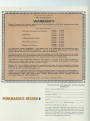
REGISTRATION
FOR MARANTZ 3-YEAR GOLDEN
WARRANTY
Model: Marantz Model 10 6 a
Serial No.
Purchaser's Name
PURCHASER'S
RECORD
~
Purchased From (Name)
Address
Price Paid $
Date Purchased
Date Warranty Reply Card Mailed
The above information becomes your permanent record of
a valuable purchase. It should be promptly filled in at the
same time that you fill in and mail the warranty registration
reply card to Marantz. Th is information provides a valuable
insurance record and must also be referred to should you
have any correspondence with Marantz.
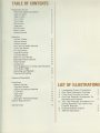
TABLEOF CONTENTS
Preparation for use
Rear PanelSignalConnection
Tape Out jacks
Tape In jacks
Aux 1 jacks
Tuner jacks
Phonojacks
Tape jacks
Pre Out jacks
Main In jacks
Chassis Ground
2
2
3
3
3
3
3
3
4
4
4
Operation
4
mic/aux 2 jacks
5
volume control
5
balance control
5
bass, mid and treble controls
5
Low Filter Switch
5
Hi Filter Switch
5
Tape Mon Switch
5
Loudness Switch
6
Mono In (L,R) Switch
6
Main-Spkr-Remote Switch
6
Power Switch
6
streophones
Some Suggestions on Using Tape Recorders
6
Your Model 1060
6
Recording and Playback
6
Copying and Editing
Technical Description
7
Functional
Selector Switch
Tape Mon Switch
balance and volume controls
Low Filter
High Filter
Amplifier
Main-Spkr-Remote Switches
General Requirements
7
7
7
7
8
8
8
8
8
Service Notes
9
',
LISTOFILLUSTRATION
1.
2.
3.
4.
II
Loudspeaker System Connections
Rear Panel Con.nection Facilities
Front Panel Controls and Jacks
One Tape Recorder Arrangement for
Recording and Playback
5. Two Tape Recorder Arrangement for
making Modified Tape Copies from
External Recorder
6. Functional Block Diagram
7. Packinq Instructions
2
3
5
6
7
8
9
:1
FOREWORD
To obtain maximum performance and enjoyment
from the Model 1060 stero console these instruc-
II tions must be studied carefully. Installing and
operating the Model 1060 is not complicated, but
I
the flexibility provided by its numerous operating
features may not be fully appreciated until a little
time is spent becoming familiar with its controls
and connections.
For convenience, this manual is divided into two'
parts. The first part covers installation and operation in a simple, non-technical manner.
The second part provides a more detailed description of the features of the Model 1060. It was
written to answer the question "What goes on
inside" and to help in situations where the Model
1060 is to be used in special appl ications. Detailed
technical specifications are also included in this
part.
For quick identification of the many controls,
connection facilities, and adjustments on the
I
Model 1060 stereo console, all references to them
in this manual are printed in bold face type. Notice
that the spelling, capitalization, abbreviation, and
punctuation of all such markings appear exactly as
lettered on the front and rear panels of the
instrument.
It will be to your advantage to save all the packing
materials carton, fillers, cushioning, etc. They will
prove valuable in preventing damage should you
ever have occasion to transport or ship the Model
1060. Be careful that you do not inadvertently
throwaway or lose the Parts packed with the unit.
Please inspect this unit carefully for any signs
of damage incurred in transit. It has undergone
very strict qual ity control inspections and tests
prior to packing. Thus it left the factory unmarred
and in perfect operating condition. If the unit was
shipped directly to you and you discover damage
notify the transportation company without delay.
Only you, the consignee, may institute a claim
with the carrier for damage during shipment.
However, the Marantz Company will cooperate
fully with you in such an event. Save the carton as
evidence of damage for their inspection. If you
received the unit directly from a Marantz dealer,
return it to him for adjustment.
1
SYSTEM 1
REPEAT
AS
+
FOR
WIRI NG
SYSTEM
1
COM.
RIGHT
LEFT
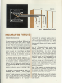
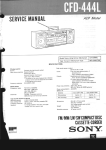
Figure1. Loudspeaker System
Connections
PREPARATION
FORUSE
Rear panel Signal Connection
All signal connections to the Model 1060 should be
made with shielded audio cables. Figure 2 shows
the location of the input and output jacks on the
rear panel. These are for "permanent" connections.
Use of the front panel controls and jacks will be
discussed later. A letter "L" corresponds to the left
audio channel; a letter "R" to right audio channel.
To avoid confusion, it is suggested that you
connect one cable at a time between the Model
1060 and the other components of your system.
This way, mixing up the channels or mixing up
signal sources and destinations will be avoided.
D
u
The SPEAKER SYSTEM (MAIN, REMOTE) jacks
on the left side of the rear panel will accomodate
two loudspeaker systems; each speaker having a
rated impedance between 4 and 16 ohms. When
using only one pair of speakers, connect them to
the terminals marked MAIN. The terminals marked
REMOTE are used for connection a second pair of
speakers in a location remote to the Model 1060.
Use care when connecting the Model 1060 to a
loudspeaker which contains a built-in power
supply-such as an electrostatic loudspeaker. The
"common" speaker-connection terminal of these
devices may be capacitively coupled through the
power supply. Ensure that the (-) terminals of the
model 1060 are connected to the "common"
terminals of the loudspeaker system as shown in
Figure 1. Ordinary #18 gauge two-conductor lamp
cord may be used for distances of up to 30 feet
between amplifier and loudspeakers. For longer
distances, use #16 gauge wire or heavier, depending
on length.
In connecting two loudspeakers for stereo operation, it is important to insure correct relative
phasing (polarity). This is best acheived, when
using identical loudspeakers, by simply coding each
wire for identification,
one wire in each pair
should be coded at both ends with a knot, tape,
etc. The coded wires can then be used for identical
connections in each channel. For example, the
coded wire in each pair can be connected to the
"common" terminal of each loudspeaker and the
(-) terminal of each amplifier channel. The uncoded wire of each pair is then connected to the
remaining loudspeaker terminal and the remaining
terminal on each amplifier channel (R and L). This
procedure insures correct polarity or phasing of
identical loudspeakers.
Note: Close inspection of standard zipcord will
reveal some form of coding on the insulation (ridge
or groove on one edge); or one of the wires may be
tinned and the other wire not tinned.
CAUTION: Never directly connect the loudspeaker
terminals of one channel in parallel with those of
any other. Any resulting damage is not covered
under warranty.
2
1:.-f1iJJ{V{)
CW vJ 1~€:
Figure
~.
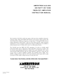
01N Tape recorder jack (REC/PLAY)-
The 5-pin
2. Rear Panel Connection
Facilities
For monophonic FM or AM tuners, proceed as
follows:
Connect one cable to either left or right
TUN ER jack. Set the front panel selector
switch to TUNER and depress both MONO
,
IN (L,R) pushswitches.
DIN tape recorder
jack on the rear panel permits
use of European-type
5-wire tape recorder cables
with similarly equipped tape recorde"rs. This jack is
connected in parallel with the TAPE IN and TAPE
OUT jacks, but the polarizing
pin in the plug
assures proper phasing at all" times.
;I~HONO
TAPE OUT jacks-The
signals available at this pair
of jacks may be routed to your tape recorder and
are affected only by the selector switch on th~
front panel.
TAPE IN jacks-With
tape recorder pre-amplifier
outputs connected to these jacks, signals from a
tape recorder can be played through your system
when the recorder is set for playback mode of
operation and the TAP E MaN switch is in the IN
position.
AUX 1 jacks-These high level jacks provide for
connecting miscellaneous sources such as tape
players with self-contained playback preamplifiers,
phono cartridges that provided R IAA equal ized
high-level output, or additional tuners or receivers,
etc.
jacks-These jacks are for use with standcartridges
requiring
a 47,000 ohm
resistive load.
If hum is heard when playing records, it is evidence
of inadequate grounding or shielding of your
record player or connections. Connect a separate
ground wire from the turntable or record changer
frame to the CHASSIS GROUND binding post on
the Model 1060. If the tone arm is mounted on a
wood panel or is otherwise insulated from the
frame, connect the arm's mounting base to the
grounding wire with a short jumper. If the two
ard
I
i
I
I
phono
pairs of signal wires in the arm have a single overall
shield, connect the shield to the grounding wire,
keep the two phono connecting cables and grounding wire closely together. In three-wire (common
ground)
systems,
this will
minimize
"ground
If excessive phono hum persists, your
loops".
phono cartridge may have a clip connecting the
I two "common" wires together, remove it.
I
I' TAPE jacks-tOo not confuse the TAPE jacks with
TUNER jacks-These high level jacks can be used
for connecting a stereo or mono tuner to the
Model 1060.
For stereo (multiplex) FM tuner reception, proceed as follows:
!
Connect a pair of audio cables between the
tuner's right and left output jacks and the
Model 1060's right and left jacks. Set the I
~
front panel selector switch to TUNER.
3
the TAPE INor TAPE OUT jacks.) An extra tape
recorder can be connected to the TAPE jacks.
When playing back with the tape recorder connected to the TAPE jacks, place the selector switch
on the front panel in the TAPE position. The
TAPE jacks are not affected by the TAPE MaN
pushswitch on the front panel.
OPERATION
PRE OUT jacks-These jacks deliver the output of
the Model 1060 preamplifier circuits to the rear
panel.
Simplified
MAIN IN jacks-These
are the input terminals of
the power amplifier section of the Model 1060.
J
plug assemblies which are provided with each
Model 1060. These assemblies must remain intact I
for normal operation of the unit. However, should
you intend to use such equipment as a graphic
equalizer, compressor/limiter,
or expander, you I
may connect these instruments to your Model:
1060 by removing the bridging connections from
the rear panel PRE OUT and MAIN IN jacks and
connecting
appropriate
length shielded audio Ii
cables from your Model 1060 to your processing
equipment.
operating
Step 1. Turn the volume control all the way to the
left (fully counter-clockwise),
and set the balance
control to mid-position.
Step 2. Set MONO IN (L,R) pushswitch to the
OUT position.
Step 3. Set TAPE NON pushswitch to the OUT
position.
I
Step 4. Set all treble, mid and bass controls to the
center position.
CHASSIS GROUND-This
binding post provides a I
convenient
"earth"
ground point to eliminate
possible ground loops between the Model 1060 and
I'
program sources.
Convenience Outlets -Two AC outlets on the rear
panel are provided for powering associated components of your system, such as power amplifiers,
Procedures-When
Later 0 n, you can take fu II advantage of the
instrument's
versatility
by learning to use the
remaining controls and adjustments.
Note: The PRE OUT and MAIN IN jacks are
normally bridged by two molded RCA type pin
1
Operating
the Model 1060 Stereo Console for the first time,
follow
these simple directions, using Figure 3.
Step 5. Depressthe POWER $witch. The pilot light
at the right center of the panel will glow.
Step 6. Select the desired
turning the selector switch
position-unless the desired
recorded tape to be played
program source by
to the appropriate
program source is a
by the taperecorder
which is connected to the DIN type recorder jack
or TAPE IN jacks. MIC,PHONO,TAPE, AUX 10r
AUX 2 may be sele~ted, by the selector switch.
~
tuners, tape recorders, record players, etc. The
right one is controlled by the front panel POWER,
switch. The UNSWITCHED outlet is not controlled
by the POWER switch. This outlet is for powering
a turntable or record changer that has its own
on-off switch.
The TAPE, TUNER or AUX 1 positions select the
program sources connected to the corresponding
input jacks on the rear panel.
I
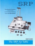
mic/aux 2 jacks-These jacks accept the standard
2-conductor phone plug.
1. When one low level microphone (less than
100mV, such as a dynamic type) is connected
to the "L" jack of the mic/aux 2 jacks, place
the selector switch in the MIC position. The
sound can be heard through the left channel
loudspeaker. I n this case depress the MONO IN
(L) pushswitch to listen the sound from both
channel loudspeakers.
If the microphone is
connected to the IIR" jack, depress the MONO
IN (R) pushswitch to hear the sound through
both channel speakers and release the (R) pushswitch to listen the sound through R channel
speaker only.
4
i8
I
,
..
IOt_oopho......
r...ic: ;un",,"...,
(i)
.
po-,.
<I
Ct
r
L
Figure
2. When two microphones are connected to the
each Rand L jack with the MONO IN (L,R)
pushswitch in the normal OUT position, the
sound can be heard in stereophonic mode. With
the MONO IN (L,R) pushswitch depressed, the
Land R channel sounds are mixed and heard in
monophonic mode.
3.
When high level signal sources (more than
100mV) are connected to the one or both
mic/aux 2 jacks, place the selector switch in
the AUX 2 position. Do not place the selector
switch in the MIC position to avoid undesirable
distortion due to signal overload.
Signal source connected to the "L" jack is
heard through the L channel speaker, if the
MONO IN (L) pushswitch is not depressed,
normal OUT position. If the (L) pushswitch is
depressed, the sound can be heard through
both left and right channel speakers.
When two kind of high level signal sources are
connected to the "L" and "R" jacks, keep the
MONO IN (L,R) pushswitches in their normal
OUT position for stereo operation and depress
both the switches for mono operation.
volume control-This control maintains stereo
balance within 3dB at all normal settings. It
controls the level of both output channels simultaneously. It has no effect on the TAPE OUT
jacks.
balance control-This control alters the level of
either output channel in situations where it is
necessary to correct unbalanced programs sometimes encountered in older stereo recordings, and
in some present-day stereo broadcasts. As it is
turned away from its center position, it decreases
the level in one output channel while maintaining
the level in the other channel.
5
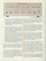
I
3. Front Panel Controls and Jacks
1
bass, mid and treble controls-These controls alter
the tonal balance of program signals to suit
individual listening preference. Because each control is separate, it is possible to compensate for
unbalanced room acoustics.
LOW FILTER Switch-This switch can be used to
sharply reduce turntable rumble, low frequency
noises, or "boomy exaggerated" bass. Obviously,
use of the filter wi II reduce desired low frequency
sounds as well as unwanted noises, therefore it
should be used judiciously. The out position
switches the filter out of the circuit.
Hi FILTER Switch-This switch can be used to
sharply reduce high-frequency noises associated
with the playing of poorly recorded tapes or old
worn disc recordings. If an AM tuner is being used
with the Model 1060, this switch will help considerably by eliminating the 10 KHz "whistle"
effect. In the a UT position, the h igh-frequency
filter is switched out of the circuits.
TAPE MaN Switch-When this two-position switch
isin its normal OUT position, the program source
being heard or recorded is determined by the
setting of the selector switch. In the IN position,
only the program source connected to the TAPE
IN jacks or DIN tape recorder jack on the rear
panel is heard. However, the program source
indicated by the selector switch continues to be
fed to the TAPE OUT jacks. This facility permits
you to feed any program source to your main tape
recorder while you listen to the "results" of the
recroding as it is in the progress.
LOUDNESS Switch-For
more pleasing tonal
balance at low level listening, the bass and treble
should be boosted. With the LOUDNESS switch
depressed, the bass and treble are automatically
,.
'I
,II
1
boosted at low level listening and this tonal balance
maintained.
MONO IN (L,R) Switch-Depressing both MONO
IN (L,R) pushswitches will convert all input signals
to the monophonic mode, including signals at the
rear panel TAPE OUT and front panel mic/aux 2
jacks.
While playing a single channel source such as TV or
AM, depress both MONO IN (L,R) pushswitches to
feed the signal through both channels.
When playing
'I
I
Recording
and Playback-The
simplest system
involves only one tape recorder, whose line or
II
'11
connected to the DIN tape recorder jack or TAPE
IN and OUT jacks on the rear panel will be referred
to as the "main" recorder; a separate recorder
usually connected to the rear panel TAPE jacks
will be referred to as the "external" recorder. This
general arrangement is shown in Figure 4.
a monophonic
use these pushswitches
phonograpn
to suppress
mon mode noise and pinch-effect
rumble,
record,
com-
distortion.
MAIN-SPKR-REMOTE Switch-These
switches
select the loudspeaker terminals to which audio
power is fed. Either the MAl N or the REMOTE
pair of loudspeakers may be selected individually,
or both loudspeaker systems may be selected
simultaneously. When both switches are set in
normal OUT position, all loudspeaker terminals are
internally disconnected from the power amplifier
section of the Model 1060. The stereophone jack,
however, is always connected and is not affected
by these switches.
POWER Switch-This switch applies AC power to
the Model 1060 and to the SWITCHED convenience outlets when depressed. When depressed
again, AC power is removed.
"rad io" inputs are connected to the TAPE OUT
jacks on the rear panel of the Model 1060, and
whose playback outputs are connected to the
TAPE IN jacks.
To make a recording, set the selector switch to the
desired program source and set the recorder to
"record." With the TAPE MaN switch in the OUT
position, you can listen to the original program
source. By setting the TAPE MaN switch to the IN
position, you can listen to (monitor) the "results"
of the recording while it is in progress.
Copying and Editing
Using the input/output and control facilities of the
Model 1060, and two tape recorders, you can copy
and edit tapes from one machine to the other. The
general arrangement of the equipment for copying
Figure 4.
r
--,-,
One Tape Recorder Arrangement for Recording
and Playback
--,.,
".,-...--
stereophones-'-This jack is internally connected to
the left and right outputs. The sterephones jack is
designed for use with professional stereo head-
j
I
phones. Two sets of headphones may be used with
the aid of "Y" connection. However, it must be
cautioned that a parallel connection of two low
I
impedance headphones results in a 3 dB loss in
level. A series connection wi II provided more
power for this purpose. Higher impedance phones
may be easily connected in parallel.
I
j
Some Suggestions on Using Tape Recorders with
Your Model 1060
There are several ways to connect and operate tape
recorders with the Model 1060. To avoid confusion
in the following discussion, references to "tape
monitoring" assumethe recorder is equipped with
separate record and playback heads and separate
record and playback preamplifiers. To further
simplify this discussion, a tape recorder usually
J.
i
"
j
IYIODEli, 1060
"--
_J
6
LOW FILTER-The
switch is to switch
low filter provides
shown in Figure 8.
Hz.
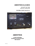
function of the LOW FILTER ~~ Amplifier-The amplifier section of the Model
in or bypass the low filter. The Ii 1060 provides 30 watts RMS output per channel
6 dB or foil off per octave, as II (with both channels driven into 8 ohms) to tlie
speaker systems.
Cutoff frequency is about 100
I
II
HIGH FILTER-The
high filter
operates in the
I
same manner as the low filter with cutoff frequency
~
of 3.5 KHz, as shown in Figure 8.
I
-
tl
MAl N-SPKR-REMOTE switches-These
switches
allows a choice of three possible combinations for
routing the audio output of the Model 1060,
MAl N REMOTE or BOTH systems. The stereophone jack remains connected at either or both
pushswitch(es) are depressed or not.
-
~ ~- --
-=---
-- ~-----
AUX1
TAPE
SPEAKERS
SYSTEMS
FROMRlGHf CHANNEL
I
1
=-
---
~-----
- ----
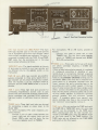
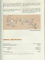
Figure 6. Functional Block Diagram
GENERALREQUIREMENTS
Power Requirement.
. . . . . . . . . . . . . . . . . . . . . . . . . . . . . . . . . . . . . . . . . . .120V AC 50 to 60Hz
At rated output both channels operating. . . . . . . . . . . . . . . . . . . . . . . . . . . . . . . . . . . . . . 190 watts
Idling Power (volume control at zero)
48 watts
Dimensions-Panel width. . . . . . . . . . . . . . . . . . . . . . . . . . . . . . . . . . . . . . . . . . . . 14-11/64 inches
Panel Height. . . . . . . . . . . . . . . . . . . . . . . . . . . . . . . . . . . . . . . . . .. 4-23/32 inches
Depth
..
11-1/32 inches
Weight-Unit alone. . . . . . . . . . . . . . . . . . . . . . . . . . . . . . . . . . . . . . . . . . .
Packed for shipment. . . . . . . . . . . . . . . . . . . . . . . . . . . . . . . . . . . .
*
. . . . . . . .18 Ibs
25.3 Ibs
These specifications and exterior designs may be changed for improvement without advance notice.
8
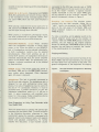
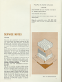
Please Pack the Amplifier as Illustrated.
CAUTION
Please DO NOT ship you[, Amplifier mounted in
its
accessory walnut cabinet.
Insure Amplifier for full value:
Make sure that your correct return address is on
shipping label.
Ship via a reputable carrier. DO NOT USE
sure to obtain receipt from
PARCEL POST-Be
carner.
- ~- ,-~- -
SERVICENOTES
REPAIRS
Only the most competent
and qualified service
technicians should be allowed to service the Marantz Model 1060 Audio Amplifier. The Marantz
Company and its warranty station personnel have
the knowledge and special equipment needed for
the repair and calibration of this precision instrument.
In the event of difficulty, write directly to the
factory (to the attention of the technical service
department)
for the name and address of the
nearest Marantz warranty or authorized
service
station. Please include the model and serial number
I
of the unit together with a description of the I
problem.
If it should ever be necessary to ship the unit to
the factory or authorized service station, and
your amplifier is mounted in its accessory walnut
cabinet, ALWAYS REMOVE IT FROM THE
CABINET BEFORE PACKING.
DO NOT SHIP THE ACCESSORY WALNUT
CABINET.
Pack the unit carefully, using the original packing
material. If the packing material has been discarded, lost, or damaged, write to the factory (to the
il
attention of the technical service department) for
II
new packing material. Carton, fillers, and packing
~I
instructions will be shipped to you at a nominal
charge. No Amplifier should be returned to the
factory without
an Authorized
Return label
~
which the Marantz company will supply if the
description
of difficulties
appears to warrant
factory service.
---
---Figure
7.
_uJ
Packing Instructions
9
...
..
IF'
The Sound of Marantz
is the compelling warmth of a Stradivarius.
It is a dancing flute, a haughty bassoon
and the plaintive call of a lone French horn.
TheSound of Marantz is the sound of beauty,
and Marantz equipment is designed to bring you
the subtle joy of its del ight.
Wonderful adventures in sound await you
when you discover that theSound of Marantz
is the sound of music at its very best.
282885101-3