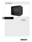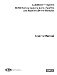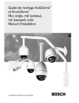
1
LTC 8786/50,LTC 8786/60
RS-232 to Biphase Converter
Installation Instructions
EN
Security you can rely on
EN
Important Safeguards
1. Read and Retain Instructions - All safety and operating
instructions should be read before the unit is operated.
Follow all operating and use instructions.
2. Heed Warnings - Adhere to all warnings on the unit and
in the operating instructions.
3. Cleaning - Unplug the unit from the outlet before cleaning. Do not use liquid cleaners or aerosol cleaners. Use a
damp cloth for cleaning.
4. Attachments - Attachments not recommended by the
product manufacturer should not be used, as they may
cause hazards.
5. Accessories - Do not place this unit on an unstable stand,
tripod, bracket, or mount. The unit may fall, causing serious injury to a person and serious damage to the unit. Use
only with a stand, tripod, bracket, or mount recommended
by the manufacturer or sold
with the product. Any mounting of the unit should
follow the manufacturer's instructions and should use
a mounting accessory recommended by the
manufacturer.
An appliance and cart combination should be moved with
care. Quick stops, excessive force, and uneven surfaces may
cause the appliance and cart combination to overturn.
6. Power Sources - This unit should be operated only from the
type of power source indicated on the label. If unsure of the
type of power supply to use, consult your dealer or local
power company. For units intended to operate from battery
power or other sources, refer to the operating instructions.
7. Power Lines - An outdoor system should not be located in
the vicinity of overhead power lines or other electric light
or power circuits or where it can fall into such power lines
or circuits. When installing an outdoor system, extreme
care should be taken to keep from touching such power
lines or circuits as contact with them might be fatal.
U.S.A. models only - refer to the National Electrical Code
Article 820 regarding installation of CATV systems.
8. Servicing - Do not attempt to service this unit yourself as
opening or removing covers may expose you to dangerous
voltage or other hazards. Refer all servicing to qualified
service personnel.
9. Replacement Parts - When replacement parts are required,
be sure the service technician has used replacement parts
specified by the manufacturer or have the same characteristics as the original part. Unauthorized substitutions may
result in fire, electric shock, or other hazards.
10. Safety Check - Upon completion of any service or repairs
to this unit, ask the service technician to perform safety
checks to determine that the unit is in proper operating
condition.
© 2003 Bosch Security Systems
Important Safeguards
11. Coax Grounding - If an outside cable system is
connected to the unit, be sure the cable system is grounded. U.S.A. models only--Section 810 of the National
Electrical Code, ANSI/NFPA No.70-1981,
provides information with respect to proper grounding of
the mount and supporting structure, grounding of the
coax to a discharge unit, size of grounding
conductors, location of discharge unit, connection
to grounding electrodes, and requirements for the
grounding electrode.
FCC & ICES Information (U.S.A. and
Canadian Models Only)
WARNING - This equipment has been tested and found to
comply with the requirements for a Class A digital device,
pursuant to Part 15 of the FCC Rules and ICES-003 of
Industry Canada. These limits are designed to provide reasonable protection against harmful interference when the equipment is operated in a residential installation. This equipment
generates, uses, and radiates radio frequency energy and, if
not installed and used in accordance with the instructions,
may cause harmful interference to radio communications.
Operation of this equipment in a residential area is likely to
cause harmful interference, in which case the user will be
required to correct the interference at his own expense.
Intentional or unintentional changes or modifications not
expressly approved by the party responsible for compliance
shall not be made. Any such changes or modifications could
void the user’s authority to operate the equipment.
If necessary, the user should consult the dealer or an experienced radio/television technician for corrective action. The
following booklet prepared by the Federal Communications
Commission may be helpful: How to Identify and Resolve
Radio-TV Interference Problems. This booklet is available
from the U.S. Government Printing Office, Washington, DC
20402, Stock No.004-000-00345-4.
WARNING: THIS IS A CLASS A PRODUCT. IN A DOMESTIC
ENVIRONMENT, THIS PRODUCT MAY CAUSE RADIO INTERFERENCE, IN WHICH CASE THE USER MAY BE REQUIRED
TO TAKE ADEQUATE MEASURES.
Page 2 of 12
EN
Safety Precautions
CAUTION: TO REDUCE THE RISK OF ELECTRICAL
SHOCK, DO NOT OPEN COVERS. NO USER SERVICEABLE
PARTS INSIDE. REFER SERVICING TO QUALIFIED
SERVICE PERSONNEL.
The lightning flash with an arrowhead symbol within an
equilateral triangle is intended to alert the user to the presence of uninsulated "dangerous voltage" within the product's enclosure that may be of sufficient magnitude to constitute a risk of electric shock to persons.
The exclamation point within an equilateral triangle is
intended to alert the user to presence of important operating and maintenance (servicing) instructions in the
literature accompanying the appliance.
WARNING: TO PREVENT FIRE OR SHOCK HAZARD, DO
NOT EXPOSE UNITS NOT SPECIFICALLY DESIGNED FOR
OUTDOOR USE TO RAIN OR MOISTURE.
Attention: Installation should be performed by qualified
service personnel only in accordance with the National
Electrical Code or applicable local codes.
Cover Removal
WARNING: REMOVAL OF THE COVER SHOULD
ONLY BE PERFORMED BY QUALIFIED SERVICE
PERSONNEL - NOT USER SERVICEABLE. THE UNIT
SHOULD ALWAYS BE UNPLUGGED BEFORE
REMOVING THE COVER AND REMAIN
UNPLUGGED WHILE THE IS REMOVED.
220-240 V, 50 Hz Power Cords
220-240 V, 50 Hz power cords, input and output, must comply
with the latest versions of IEC Publication 227 or IEC
Publication 245.
© 2003 Bosch Security Systems
Safety Precautions
Securite
DANGER: POUR ÉVITER TOUT RISQUE D'ÉLECTROCUTION, NE PAS OUVRIR LE BOÎTIER. IL N'Y A PAS DE
PIÈCES REMPLAÇABLES À L'INTÉRIEUR. POUR TOUTE
RÉVISION, S'ADRESSER À UN TECHNICIEN SPÉCIALISÉ.
L'éclair fléché dans un triangle équilatéral, avertit l'utilisateur de la présence d'une "tension dangereuse" non
isolée à l'intérieur de l'appareil et d'une valeur suffisante
pour constituer un risque d'électrocution.
Le point d'exclamation contenu dans un triangle
équilatéral, avertit l'utilisateur de la présence, dans la
documentation qui accompagne l'appareil, de consignes d'utilisation et de maintenance importantes.
ATTENTION: POUR ÉVITER LE RISQUE D'ÉLECTROCUTION OU D'INCENDIE, NE PAS EXPOSER À LA PLUIE OU
À L'HUMIDITÉ UN APPAREIL NON CONÇU POUR UNE
UTILISATION EXTÉRIEURE.
Attention: L'installation doit être effectuée uniquement
par du personnel de service qualifié conformément à la
réglementation du Code Electrique National ou à la
réglementation locale.
Sources d'alimentation extérieures
UTILISER UNIQUEMENT LES SOURCES
D'ALIMENTATION RECOMMANDÉES.
LES SOURCES D'ALIMENTATION DOIVENT ÊTRE
CONFORMES AUX RÉGLEMENTATIONS DE LA
DERNIÈRE VERSION IEC 65/VDE 0860. TOUTE MODIFICATION PEUT ENDOMMAGER L'APPAREIL OU
PROVOQUER UN INCENDIE OU UN
CHOC ÉLECTRIQUE.
Les cordons secteur 220-240 V, 50 Hz
Les cordons secteur 220-240 V, 50 Hz, entrée et sortie, doivent
êtro conformes aux versions les plus récentes de la
publication 227 de la C.I.E. ou à la publication 245 de la C.I.E.
Page 3 of 12
EN
Sicherheitsvorkehrungen
VORSICHT: UM EINEN ELEKTRISCHEN SCHLAG ZU
VERMEIDEN, ABDECKUNG NICHT ENTFERNEN.
WARTUNGEN ALLER ART QUALIFIZIERTEM
PERSONAL ÜBERLASSEN.
Das Blitzsymbol im gleichseitigen Dreieck soll den
Benutzer auf nicht isolierte "Hochspannung" im Gehäuse
aufmerksam machen, die eventuell stark genug ist, um
einen elektrischen Schlag zu verursachen.
Das Ausrufezeichen im gleichseitigen Dreieck soll den
Benutzer auf wichtige Bedienungs- und
Wartungsanleitungen in der dem Gerät beigefügten
Literatur aufmerksam machen.
WARNUNG: UM FEUER ODER ELEKTRISCHE SCHLÄGE
ZU VERMEIDEN, SETZEN SIE DAS GERÄT NIEMALS
REGEN ODER FEUCHTIGKEIT AUS.
Achtung! Die Installation sollte nur von qualifiziertem
Kundendienstpersonal gemäß jeweilig zutreffender
Elektrovorschriften ausgeführt werden.
Externe Netzgeräte
NUR VOM HERSTELLER EMPFOHLENE
NETZGERÄTE VERWENDEN! DIE NETZGERÄTE
MÜSSEN DER JEWEILS GÜLTIGEN VERSION DER
IEC 65/VDE 0860 BESTIMMUNGEN ENTSPRECHEN.
ANDERE ERSATZNETZGERÄTE KÖNNEN DAS
VORLIEGENDE GERÄT BESCHÄDIGEN UND
FEUER ODER ELEKTROSCHLAG BEWIRKEN.
220-240 V, 50 Hz Netzkabel, Eingang und Ausgang
220-240 V, 50 Hz Netzkabel, Eingang und Ausgang, muß die
neueste Version der IEC Vorschriften, Veröffentlichung 227 oder
245, erfüllen.
© 2003 Bosch Security Systems
Safety Precautions
Sicurezza
ATTENZIONE: PER RIDURRE IL PERICOLO DI SCOSSA
ELETTRICA, NON APRIRE LE COPERTURE. L’INTERNO
NON CONTIENE COMPONENTI CHE L’UTENTE PUÒ
RIPARARE PERSONALMENTE. RIVOLGERSI AL
PERSONALE DI ASSISTENZA QUALIFICATO PER
QUALSIASI INTERVENTO DI RIPARAZIONE.
Il simbolo triangolare di un fulmine con la punta a freccia
intende mettere in allerta l’utente riguardo alla presenza
di tensioni pericolose non isolate all’interno del guscio
dell’unità, che potrebbero essere di intensità sufficiente
per costituire pericolo di elettrocuzione.
Il punto esclamativo racchiuso in un triangolo equilatero
intende avvisare l’utente in merito alla presenza di importanti istruzioni operative e di manutenzione nella documentazione di accompagnamento all’unità.
AVVERTENZA: PER IMPEDIRE INCENDI O SCOSSA
ELETTRICA, NON ESPORRE L’UNITÀ ALLA PIOGGIA O
ALL’UMIDITÀ.
Precauzione: affidare l’installazione al solo personale
qualificato e nel rispetto del Codice elettrico nazionale
(USA) o dei codici locali pertinenti.
Rimozione Della Copertura
AVVERTENZA: AFFIDARE LA RIMOZIONE DELLA
COPERTURA SOLTANTO AL PERSONALE DI
SERVIZIO QUALIFICATO. L’UTENTE DEVE ASTENERSI DALL’EFFETTUARE UN INTERVENTO DI
RIPARAZIONE DI PERSONA. DISINSERIRE SEMPRE IL
CAVO DI ALIMENTAZIONE DALL’UNITÀ PRIMA DI
RIMUOVERE LA COPERTURA E NON REINSERIRLO SE LA
COPERTURA NON È STATA RICHIUSA.
Cavi di alimentazione a 220-440 V, 50 Hz
I cavi di alimentazione a 220-440 V, 50 Hz devono essere conformi
(ingresso e uscita) alle versioni più recenti della pubblicazione
IEC 227 o IEC 245.
Page 4 of 12
EN
Veiligheidsmaatregelen
VOORZICHTIG: MAAK HET APPARAAT NIET OPEN OM
DE KANS OP ELEKTRISCHE SCHOKKEN TE VERMIJDEN. BEVAT GEEN ONDERDELEN DIE DOOR DE
GEBRUIKER MOETEN WORDEN ONDERHOUDEN.
LAAT ONDERHOUD EN REPARATIES UITVOEREN
DOOR BEVOEGDE TECHNICI.
Het symbool 'Bliksemflits met pijlkop' in een gelijkzijdige
driehoek wijst de gebruiker op de aanwezigheid in de kast
van het apparaat van niet-geïsoleerde spanningen die voldoende sterk zijn om het gevaar van elektrische schokken
op te leveren.
Het uitroepteken in een gelijkzijdige driehoek maakt de
gebruiker attent op de aanwezigheid in de bij het apparaat behorende documentatie van belangrijke aanwijzingen voor bediening en onderhoud.
WAARSCHUWING: TER VOORKOMING VAN
BRANDGEVAAR EN ELEKTRISCHE SCHOKKEN MAG
DIT ARMATUUR NIET AAN REGEN EN VOCHT WORDEN BLOOTGESTELD.
Let op: Het apparaat mag uitsluitend door bevoegde technici geïnstalleerd worden en wel in overeenstemming met
de National Electrical Code of de daarvoor plaatselijk
geldende richtlijnen.
Safety Precautions
Precauciones de Seguridad
PRECAUCION: PARA REDUCIR EL RIESGO DE CHOQUE
ELÉCTRICO, FAVOR NO ABRIR LA CUBIERTA. ESTE
EQUIPO NO CONSTA DE PIEZAS O PARTES QUE
REQUIEREN SERVICIO O MANTENIMIENTO. PARA
REPARACIONES FAVOR REFERIRSE A UN TÉCNICO
CALIFICADO.
El símbolo representado por un relámpago con punta de
flecha dentro de un triángulo equilátero, se muestra con el
objetivo de alertar al usuario que existen "voltages peligrosos"
sin aislamiento, dentro de la cubierta de la unidad. Dichos
voltages pueden ser de tal magnitud que constituyen un
riesgo de choque eléctrico a personas.
El símbolo de exclamación dentro de un triángulo equilátero, se muestra con el objetivo de alertar al ususario de
que instrucciones de operación y mantenimiento importantes acompañan al equipo.
PELIGRO: PARA EVITAR EL PELIGRO DE INCENDIO Ó
CHOQUE ELÉCTRICO, NO EXPONGA A LA LLUVIA Ó
HUMEDAD, EQUIPOS QUE NO HAN SIDO DISEÑADOS
PARA USO EXTERIOR.
Atención: La instalación de este equipo debe ser realizada por
personal capacitado, solo en acuerdo, y en cumplimiento de
normas del "National Electric Code" (Código Eléctrico
Nacional) ó las normas del Gobierno Nacional Local.
Verwijderen van de Dekplaat
WAARSCHUWING: HET VERWIJDEREN VAN DE
DEKPLAAT MAG UITSLUITEND DOOR EEN
VAKKUNDIG TECHNICUS WORDEN
UITGEVOERD - REPARATIE DOOR GEBRUIKER IS
NIET GEOORLOOFD. DE NETVOEDING VAN HET
APPARAAT MOET ALTIJD WORDEN LOSGEKOPPELD
VOORDAT MEN DE DEKPLAAT VERWIJDERT EN
LOSGEKOPPELD BLIJVEN ZOLANG DE DEKPLAAT
VERWIJDERD IS.
Netvoedingskabels 220-440 V, 50 Hz
Netvoedingskabels 220-440 V, 50 Hz, voor ingang en uitgang,
moeten voldoen aan de voorschriften in de meest recente uitgave
van IEC publicatie 227 of IEC publicatie 245.
© 2003 Bosch Security Systems
Fuentes de Alimentación Externas
USAR SOLO LAS FUENTES DE ALIMENTACIÓN
RECOMENDADAS. LAS FUENTES DE
ALIMENTACIÓN DEBEN CUMPLIR CON LOS
REQUISITOS DE LA VERSIÓN MÁS RECIENTE DE LA
IEC 65/VDE 0860. EL USO DE SUBSTITUTOS PUEDE
DAÑAR LA UNIDAD, Ó CREAR PELIGRO DE
INCENDIO O CHOQUE ELÉCTRICO.
220-240 V, los cables eléctricos de 50 Hz: 220-240 V, los
cables eléctricos de 50 Hz, de entrada y de salida, deben cumplir con
las versiones mas recientes de la publicación IEC 227 ó la
Publicación IEC 245.
Page 5 of 12
EN
Medidas de Segurança
PRECAUCION: PARA REDUCIR EL RIESGO DE CHOQUE
ELÉCTRICO, FAVOR NO ABRIR LA CUBIERTA. ESTE
EQUIPO NO CONSTA DE PIEZAS O PARTES QUE
REQUIEREN SERVICIO O MANTENIMIENTO. PARA
REPARACIONES FAVOR REFERIRSE A UN TÉCNICO
CALIFICADO.
O símbolo do raio com a cabeça de uma seta dentro de um
triângulo equilátero serve para alertar o utilizar para a presença de "corrente eléctrica perigosa" não isolada no interior
da caixa do produto que pode ser suficiente para dar origem
a choques eléctricos.
O ponto de exclamação dentro de um triângulo equilátero serve
para alertar o utilizador para a presença de instruções de funcionamento e manutenção importantes na documentação
fornecida com o aparelho.
AVISO: PARA EVITAR INCÊNDIOS OU CHOQUES
ELÉCTRICOS, NÃO EXPONHA À CHUVA OU
HUMIDADE UNIDADES NÃO ESPECIFICAMENTE
CRIADAS PARA UTILIZAÇÃO NO EXTERIOR.
Atenção: A instalação deve ser efectuada por pessoal de
assistência técnica qualificado, de acordo com o National
Electrical Code (Normas de Electricidade Nacionais) ou a
legislação local aplicável.
Remoção da Tampa
ATENÇÃO: A TAMPA DEVE SER REMOVIDA APENAS PELO PESSOAL DA ASSISTÉNCIA TÉCNICA
QUALIFICADA. ESTA UNIDADE NÃO CONTÉM
PEÇAS REQUEREM MANUTENÇÃO PELO
USUÁRIO. ANTES DE REMOVER A TAMPA, CERTFIQUE-SE DE QUE O EQUIPAMENTO FOL
DESCONECTADO DA ALIMENTAÇÃO. ESTE DEVE
PERMANECER DESCONECTADO ENQUANTO A
TAMPA ESTIVER FORA DO SEU LUGAR.
Safety Precautions
Zasady Bezpieczeństwa
UWAGA: ZE WZGLĘDU NA NIEBEZPIECZEŃSTWO
PORAŻENIA PRĄDEM NIE WOLNO OTWIERAĆ
POKRYWY. W ŚRODKU NIE MA ŻADNYCH ELEMENTÓW, KTÓRE MOGĄ BYĆ NAPRAWIANE PRZEZ
UŻYTKOWNIKA. NAPRAWĘ NALEŻY POWIERZYĆ
AUTORYZOWANEMU PUNKTOWI SERWISOWEMU.
Błyskawica ze strzałką wewnątrz trójkąta równobocznego ma
za zadanie zwrócić uwagę użytkownika na obecność
nieizolowanego "niebezpiecznego napięcia" wewnątrz
obudowy urządzenia, o wielkości stwarzającej
niebezpieczeństwo porażenia prądem.
Wykrzyknik wewnątrz trójkąta równobocznego ma za zadanie
zwrócić uwagę użytkownika na ważne czynności, związane z
obsługą i konserwacją urządzenia, zamieszczone w Instrukcji
obsługi.
OSTRZEŻENIE: ABY UNIKNĄĆ POŻARU LUB
PORAŻENIA PRĄDEM NIE WOLNO WYSTAWIAĆ NA
DZIAŁANIE DESZCZU LUB WILGOCI URZĄDZEŃ,
KTÓRE NIE ZOSTAŁY SPECJALNIE ZAPROJEKTOWANE DO UŻYWANIA NA OTWARTYM POWIETRZU.
Uwaga: Instalację urządzenia powinien wykonać tylko wykwalifikowany personel, zgodnie z przepisami NEC lub odpowiednimi przepisami miejscowymi.
Otwieranie Obudowy
UWAGA: OBUDOWA URZĄDZENIA MOŻE BYĆ
OTWIERANA TYLKO PRZEZ WYKWALIFIKOWANY PERSONEL. PRZED OTWARCIEM
OBUDOWY WYJĄĆ WTYCZKĘ Z GNIAZDA
SIECIOWEGO.
Kable zasilające 220–240 V, 50Hz
Kable zasilające 220–240 V, 50Hz, wejścia i wyjścia muszą być zgodne
z ostatnią wersją publikacji nr 227 lub 245 IEC.
Cabos de alimentação 220-240 V, 50HZ
Os cabos de alimentação 220-240 V, 50 HZ , entrada ou saída, devem
estar de acordo com as ultimas versões do IEC
Publicação 227 ou do IEC Publicação 245.
© 2003 Bosch Security Systems
Page 6 of 12
EN
Table of Contents
1
2
3
4
5
6
7
8
9
DESCRIPTION . . . . . . . . . . . . . . . . . . . . . . . . . . . . . . . . .7
UNPACKING . . . . . . . . . . . . . . . . . . . . . . . . . . . . . . . . . . .7
SERVICE . . . . . . . . . . . . . . . . . . . . . . . . . . . . . . . . . . . . . . .7
POWER . . . . . . . . . . . . . . . . . . . . . . . . . . . . . . . . . . . . . . . .7
INSTALLATION . . . . . . . . . . . . . . . . . . . . . . . . . . . . . . . . .8
5.1 Mounting . . . . . . . . . . . . . . . . . . . . . . . . . . . . . . . . . .8
5.2 Power Supply Connections . . . . . . . . . . . . . . . . . . . .8
5.3 Data Input Connections . . . . . . . . . . . . . . . . . . . . . .8
5.4 PC RS-232 Interface Using a 9-Pin Connector . . . .8
5.5 RS-232 Interface Using RJ-11 Connector . . . . . . . .8
5.6 Remote RS-232 Device Interface . . . . . . . . . . . . . . .8
5.7 Data Output Connection . . . . . . . . . . . . . . . . . . . . .9
5.8 AutoDome Camera or Receiver/ Driver
Site Configuration . . . . . . . . . . . . . . . . . . . . . . . . . . .9
OPERATION . . . . . . . . . . . . . . . . . . . . . . . . . . . . . . . . . . . .9
TYPICAL CONFIGURATIONS . . . . . . . . . . . . . . . . . . . .10
PIN OUTS . . . . . . . . . . . . . . . . . . . . . . . . . . . . . . . . . . . . .11
DIMENSIONS . . . . . . . . . . . . . . . . . . . . . . . . . . . . . . . . . .11
1 DESCRIPTION
The LTC 8786 Series of data converters are designed to
convert Bosch "Receiver/driver and AutoDome RS-232
Control Code Protocol" into Allegiant biphase control code.
These units are specifically designed to transform the single
data output from a DÉSA DVR (or a similar device) into
multiple control code outputs for operating AutoDome
cameras.
The Bosch "Receiver/driver and AutoDome RS-232 Control
Code Protocol" is a simplex RS-232 data format designed
to communicate with the Bosch line of receiver/drivers,
AutoDome cameras, LTC 8786 converters, and other
compatible accessory devices. Complete information on the
protocol can be obtained by downloading the manual from
the AutoDome section of www.boschsecurity.com.
Introduction
2
UNPACKING
This electromechanical equipment should be unpacked and
handled carefully:
■
■
■
■
■
LTC 8786/50 or LTC 8786/60 Data Converter unit.
Power supply adapter.
1.8m (5.75) power supply cable with bayonette plug.
Subminiature 9-Pin D connector.
Four (4) adhesive backed rubber feet.
If an item appears to have been damaged in shipment, replace
properly into the carton and notify the shipper. If any items
are missing, notify your Bosch Security Systems Sales
Representative or Customer Service Representative. The
shipping carton is the safest container in which the unit may
be transported. Save it for possible future use.
3
SERVICE
If the unit ever needs repair service, the customer should
contact the nearest Bosch Security Systems Service Center for
authorization to return and shipping instructions.
Service Centers
U.S.A.: Phone: 800-366-2283 or 408-956-3895
fax:
800-366-1329 or 408-956-3896
e-mail: [email protected]
Canada:
514-738-2434
Europe, Middle East & Asia Pacific Region:
32-1-440-0711
For additional information,
see www.boschsecuritysystems.com.
4
Power
Model
Rated Voltage
Voltage Range
LTC 8786/60 120 VAC, 50/60 Hz 105 to 132 VAC
LTC 8786/50 220-240 VAC,
195.5 to 253 VAC
50/60 Hz
* At rated voltage.
Power*
3W
3W
The input RS-232 baud rate of the LTC 8786 Series is fixed
at 9600 baud, 1 stop bit, 8 data bits, no parity, and no
handshake.
The LTC 8786 Series units can be connected directly to the
RS-232 serial port of a PC using an industry standard null
modem cable. If another connection type is required, an
interface cable can easily be constructed using the supplied
9-Pin D connector.
The supplied power supply provides power to the LTC 8786
Series unit.
© 2003 Bosch Security Systems
Page 7 of 12
EN
5 INSTALLATION
5.1
Mounting
The LTC 8786 Series Data Converters are rated for indoor use
only. If desired, four (4) holes are provided for mounting the
unit to a flat surface. See MOUNTING DIMENSIONS at the
end of this document.
If using on a desktop, attach the supplied rubber feet to the
bottom of the unit.
A cable suitable for use with RS-232 signals (not supplied)
must be used between the RS-232 device and the LTC 8786
unit. If the distance between the RS-232 device and the LTC
8786 unit is over 20-30 meters (60-90 ft), the use of 'short
haul modems' (not supplied) or other RS-232 line extender
devices may be required. An RS-232 simplex transmission rate
of 9600 baud will need to be supported by the link.
5.2 Power Supply Connections
Install the LTC 8786 unit within 1.8m (5.75) of the mains
power source. Connect the 'bayonet' style connector of the
power supply cable into the jack located on the side of the
converter unit. Plug the power supply adapter into a
suitable AC power source.
If the power supply must be located beyond 1.8m, the
provided power supply cable can be extended, or replaced
with an appropriate user-supplied cable. The LTC 8786
is not polarity-sensitive, so it does not matter which
direction the cable is attached to the power supply adapter.
If desired, a user-provided power supply may be used
with the data converter. A power supply having either a
15-20 VDC ± 10%, 400 mA or 12-18 VAC ± 10%,
400 mA output is required.
Installation
5.4 PC RS-232 Interface Using a 9-Pin
Connector
In this application, the LTC 8786 is connected directly to the
serial port of a PC. The user-supplied software installed on
the PC must be designed to output "Receiver/driver and
AutoDome RS-232 Control Code Protocol" data. This RS-232
data is converted into Allegiant biphase protocol using the
LTC 8786 unit. The biphase data is then connected to the
AutoDome cameras or Allegiant receiver/driver units as
described herein.
Attach an RS-232 standard null modem cable (part No.
S1385) to the serial port of the PC. Connect the other end of
the data cable to the 9-pin connector on the LTC 8786 converter unit.
Skip to the section on AUTODOME CAMERA OR
RECEIVER/DRIVER SITE CONFIGURATION to complete
the installation.
5.5 RS-232 Interface Using RJ-11
Connector
Connect one end of a suitable data cable to the RJ-11 jack
on the LTC 8786 converter unit. The other end of the cable
must now be interfaced to the RS-232 communication link.
Only the RX and SIGNAL GROUND connections are
required. The remaining pinouts should remain 'un-connected'.
If the distance between the RS-232 communication link and
the LTC 8786 converter unit is greater than 3 m (10), install
an appropriate length of cable suitable for use with RS-232
signals (user-supplied). Since the data format is an RS-232
simplex transmission, only 2 signal wires (DATA and
GROUND) will be required.
If necessary, replacement power supply adapters can be
ordered as noted below:
If the distance between the LTC 8786 unit and the camera site
is over 20-30 m (60-90 ft), the use of short haul modems
(user-supplied) or other RS-232 line extender devices may be
required. They must be able to support an RS-232 simplex
transmission rate of 9600 baud.
120 VAC input: KBD-120PS Power supply and power cable.
230 VAC input: KBD-220PS Power supply and power cable.
The wiring pinouts of the LTC 8786 series is shown in the
PINOUTS section.
5.3 Data Input Connections
Two (2) data input connections to the converter unit
are available. Only one can be used at a time, and the choice
varies depending upon the specific application. Although various connection options are possible, typical applications are
described in the sections that follow. Use whichever
application is most suitable to your configuration. Typical
configuration diagrams are included in this manual for
reference.
5.6 Remote RS-232 Device Interface
In this application, Allegiant biphase control code is being
converted into RS-232 which is then transmitted over an
RS-232 communication link (fiber optics, microwave, dial-up
phone modems, etc.). At the camera side end of the RS-232
transmission link, the RS-232 data is converted back into
Allegiant biphase protocol via the LTC 8786 unit. The
biphase data is then connected to AutoDome cameras or
Allegiant receiver/driver units.
The RS-232 communication link must be able to support an
RS-232 simplex transmission rate of 9600 baud.
© 2003 Bosch Security Systems
Page 8 of 12
EN
5.7 Data Output Connection
The LTC 8786 Series provides sixteen biphase control code
outputs. Connect a shielded twisted-pair cable (BELDEN
8760 or equivalent) from a biphase control code output of the
converter unit to the camera site. Typically, a single camera
site receiver/driver or AutoDome is connected, but the
biphase output of the converter unit is rated to handle up to
8 devices when connected in a daisy chain configuration to a
maximum of 1.5 km (5000 ft). For a daisy chain connection,
the cable is looped through each AutoDome camera or
receiver/driver along the way. Only the last unit in the daisy
chain connection should be terminated. All other
receiver/drivers should have their terminating resistor
removed when the looping cable is connected.
The removable terminal blocks for the biphase code outputs
have three connections: (+), (S) (Shield), and (–) for each of
the sixteen biphase code outputs as shown in FIGURE 1.
Operation
5.8
AutoDome Camera or
Receiver/Driver Site Configuration
Follow the standard installation instructions provided with
the AutoDome Camera or Allegiant Series Receiver/Driver
unit for setting device address and connecting the data cable
to the unit.
Video signals from the camera site are NOT associated with
this product. The video signal(s) from the camera site(s)
should be connected to an appropriate viewing monitor or
other video processing equipment (switcher, PC video capture
card, etc.).
6 OPERATION
Operation of the LTC 8786 Series is automatic. An LED, visible on the top cover of the unit, will flash to indicate that the
unit has converted RS-232 data into biphase control code. No
programming or other user adjustments are required.
Pin 1
Pin 6
Figure 1 LTC 8786 Data Converter Connections
Select and maintain a wire color convention to avoid confusion at the camera site(s).
Example: White to (+), (Shield) to (S), and Black to (–).
NOTE The shield terminal of the interface unit is connected
to the shield wire of the cable.
© 2003 Bosch Security Systems
Page 9 of 12
EN
Technical Reference
7 TYPICAL CONFIGURATIONS
LTC 8786
Power
Supply
Adapter
RS-232 Data
LTC 8786
Converter
Video Signal
Up to 16 biphase control
code outputs
Video Signal
Typical DÉSA Digital Video
Recorder or other device running
user-supplied video/control software
Typical AutoDome
Cameras or Allegiant
Receiver/Driver units
Figure 2 Using PC Or DÉSA Digital Video Recorder As Source Of RS-232 Data
LTC 8786 Power
Supply Adapter
LTC 8780
Data Converter
Video
Monitor
Biphase
Data
ALLEGIANT Video System
POWER
Allegiant System
RS-232
Data
RS-232
Data
Video
Signal
Video and RS-232
Communication Link
LTC 8786
Converter
Up to 16 biphase
control code
outputs
Video Signal
CODE OUT
ALARM
STATUS
BATTERY LOW
Allegiant
Keyboard
Typical AutoDome
Cameras or Allegiant
Receiver/Driver units
Figure 3 When Used as Remote RS-232 To Biphase Data Converter
© 2003 Bosch Security Systems
Page 10 of 12
EN
Technical Reference
8 PINOUTS
9 MOUNTING DIMENSIONS
154
6.08
Data In - 9-Pin Connector (Male)
Pin
1
2
3
4
5
6
7
8
9
Connection
No Connection
Rx
No Connection
No Connection
Ground
No Connection
No Connection
No Connection
No Connection
122
4.80
108
4.26
70
2.75
RJ-11 Designations (If Used)
mm
in
Figure 4 Top Dimensions
Pin
Connection
1
Output Voltage
2
3
4
5
Signal Ground
Rx
Ground
No Connection
6
Output Voltage
1
127
5.0
1
38
1.5
1. These connections should be left unconnected in this configuration.
1
Industry Standard PC Null Modem Interface Cable
(Purchased separately- Part No. S1385)
LTC 8786 Side
(9-Pin Female)
PC or DVR Side
(9-Pin Female)
Pin
1
2
3
4
5
6
7
8
9
Pin
4
3
2
1, 6
5
-8
7
--
132
5.2
mm
in
Figure 5 Side Dimensions
1. The LTC 8786 only requires connections to pin 2 and 5 of its 9-Pin
connector.
© 2003 Bosch Security Systems
Page 11 of 12
Bosch Security Systems, Inc.
850 Greenfield Road
Lancaster, PA 17601 U.S.A.
Tel: 800-326-3270
Fax: 1-717-735-6560
Bosch Security Systems B.V.
P.O. Box 80002, 5600 JB
Eindhoven
The Netherlands
Tel: 31 40 278 1222
Fax: 31 40 278 6668
Bosch Singapore Pte. Ltd.
620A, Lorong I Toa Payoh
Singapore 319762
Republic of Singapore
Tel: 65 350 1859
Fax: 65 356 9202
Printed in USA
3935 890 45511 03-08
March 26, 2003
Security you can rely on