1
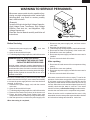
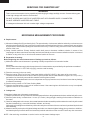
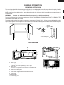
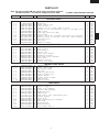
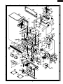
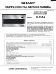
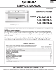
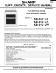
R-2130JS
SUPPLEMENTAL SERVICE MANUAL
S94M2R2130JS/
OVER THE RANGE
MICROWAVE OVEN
MODEL
R-2130JS
In the interest of user-safety the oven should be restored to its original condition and only parts identical to those specified should
be used.
WARNING TO SERVICE PERSONNEL: Microwave ovens contain circuitry capable of producing very high voltage
and current. Contact with the following parts may result in a severe, possibly fatal, electrical shock. (Inverter unit
that includes High Voltage Capacitor, High Voltage Power Transformer, High Voltage Rectifier and Heat sink etc.,
and Magnetron, High Voltage Harness etc..)
TABLE OF CONTENTS
Page
PRECAUTIONS TO BE OBSERVED BEFORE AND DURING SERVICING TO
AVOID POSSIBLE EXPOSURE TO EXCESSIVE MICROWAVE ENERGY ................. INSIDE FRONT COVER
BEFORE SERVICING .................................................................................................... INSIDE FRONT COVER
WARNING TO SERVICE PERSONNEL .............................................................................................................. 1
MICROWAVE MEASUREMENT PROCEDURE .................................................................................................. 2
FOREWORD AND WARNING ............................................................................................................................. 3
PRODUCT SPECIFICATIONS ............................................................................................................................ 4
PARTS LIST ........................................................................................................................................................ 7
PACKING AND ACCESSORIES ....................................................................................................................... 11
This document has been published to be used for after
sales service only.
The contents are subject to change without notice.
SHARP CORPORATION
1
R-2130JS
PRECAUTIONS TO BE OBSERVED BEFORE AND DURING SERVICING TO AVOID POSSIBLE EXPOSURE TO
EXCESSIVE MICROWAVE ENERGY
(a) Do not operate or allow the oven to be operated with the door open.
(b) Make the following safety checks on all ovens to be serviced before activating the magnetron or other microwave
source, and make repairs as necessary: (1) interlock operation, (2) proper door closing, (3) seal and sealing
surfaces (arcing, wear, and other damage), (4) damage to or loosening of hinges and latches, (5) evidence of
dropping or abuse.
(c) Before turning on microwave power for any service test or inspection within the microwave generating
compartments, check the magnetron, wave guide or transmission line, and cavity for proper alignment, integrity,
and connections.
(d) Any defective or misadjusted components in the interlock, monitor, door seal, and microwave generation and
transmission systems shall be repaired, replaced, or adjusted by procedures described in this manual before the
oven is released to the owner.
(e) A microwave leakage check to verify compliance with the Federal Performance Standard should be performed
on each oven prior to release to the owner.
BEFORE SERVICING
Before servicing an operative unit, perform a microwave emission check as per the Microwave
Measurement Procedure outlined in this service manual.
If microwave emissions level is in excess of the specified limit, contact SHARP ELECTRONICS
CORPORATION immediately @1-800-237-4277.
If the unit operates with the door open, service person should 1) tell the user not to operate the oven and
2) contact SHARP ELECTRONICS CORPORATION and Food and Drug Administration's Center for
Devices and Radiological Health immediately.
Service personnel should inform SHARP ELECTRONICS CORPORATION of any certified unit found with
emissions in excess of 4mW/cm2. The owner of the unit should be instructed not to use the unit until the
oven has been brought into compliance.
DANGER CAUTION
HIGH VOLTAGE
Do not energize a microwave oven with the outer case cabinet removed, because a microwave oven
generates High Voltage in the circuit.
If you intend to operate the oven employing the high frequency switching power converter circuit, you should
take special precautions to avoid an electrical shock hazard.
The high voltage transformer, high voltage capacitor and high voltage diode have energized high voltage
potential approx. 8 KV.
The aluminium heat sink is connected to the switching power transistor Collector pole, and has an energized
high voltage potential approx. 650V peak.
DO NOT ACCESS THE HIGH VOLTAGE TRANSFORMER, HIGH VOLTAGE CAPACITOR, HIGH VOLTAGE DIODE AND HEAT SINK WHEN THE POWER SUPPLY IS CONNECTED TO AN ELECTRICAL
OUTLET.
2
R-2130JS
WARNING TO SERVICE PERSONNEL
Microwave ovens contain circuitry capable of producing very high voltage and current, contact with
following parts may result in a severe, possibly
fatal, electrical shock.
(Example)
Inverter unit that includes High Voltage Capacitor,
High Voltage Power Transformer, High Voltage
Rectifier, Heat sink etc., and Magnetron, High
Voltage Harness etc..
Read the Service Manual carefully and follow all
instructions.
Don't Touch !
Danger High Voltage
1. Disconnect the power supply cord, and then remove
outer case.
2. Open the door and block it open.
3. To discharge high voltage capacitor, wait for 60 seconds.
4. Reconnect the leads to the primary of the inverter unit.
5. Reinstall the outer case (cabinet).
6. Reconnect the power supply cord after the outer case is
installed.
7. Run the oven and check all functions.
Before Servicing
1. Disconnect the power supply cord
, and then
remove outer case.
2. Open the door and block it open.
3. To discharge high voltage capacitor, wait for 60 seconds.
WARNING:RISK OF ELECTRIC SHOCK.
DISCHARGE THE HIGH-VOLTAGE
CAPACITOR BEFORE SERVICING.
After repairing
The high-voltage capacitor remains charged about 60
seconds after the oven has been switched off. Wait for 60
seconds and then short-circuit the connection of the highvoltage capacitor (that is the connecting lead of the highvoltage rectifier) against the chassis with the use of an
insulated screwdriver.
1. Reconnect all leads removed from components during
testing.
2. Reinstall the outer case (cabinet).
3. Reconnect the power supply cord after the outer case is
installed.
4. Run the oven and check all functions.
Whenever troubleshooting is performed the power supply
must be disconnected. It may in, some cases, be necessary
to connect the power supply after the outer case has been
removed, in this event,
1. Disconnect the power supply cord, and then remove
outer case.
2. Open the door and block it open.
3. To discharge high voltage capacitor, wait for 60 seconds.
4. Disconnect the leads to the primary of the inverter unit.
5. Ensure that these leads remain isolated from other
components and oven chassis by using insulation tape.
6. After that procedure, reconnect the power supply cord.
Microwave ovens should not be run empty. To test for the
presence of microwave energy within a cavity, place a cup
of cold water on the oven turntable, close the door and set
the power to HIGH and set the microwave timer for two (2)
minutes. When the two minutes has elapsed (timer at zero)
carefully check that the water is now hot. If the water
remains cold carry out Before Servicing procedure and reexamine the connections to the component being tested.
When all service work is completed and the oven is fully
assembled, the microwave power output should be checked
and microwave leakage test should be carried out.
When the testing is completed,
1
R-2130JS
SERVICING FOR INVERTER UNIT
WARNING
This inverter unit contains circuitry capable of producing high voltage and high current. Contact with any part
of the high voltage will result in electrocution.
DO NOT ACCESS ANY PARTS OF INVERTER UNIT WITH POWER SUPPLY CONNECTED.
DO NOT OPERATE INVERTER UNIT ITSELF.
It is dangerous because this unit contains high voltage components.
MICROWAVE MEASUREMENT PROCEDURE
A. Requirements:
1) Microwave leakage limit (Power density limit): The power density of microwave radiation emitted by a microwave oven
should not exceed 1mW/cm2 at any point 5cm or more from the external surface of the oven, measured prior to acquisition
by a purchaser, and thereafter (through the useful life of the oven), 5 mW/cm2 at any point 5cm or more from the external
surface of the oven.
2) Safety interlock switches: Primary interlock switch shall prevent microwave radiation emission in excess of the
requirement as above mentioned, secondary interlock switch shall prevent microwave radiation emission in excess of
5 mW/cm2 at any point 5cm or more from the external surface of the oven.
B. Preparation for testing:
Before beginning the actual measurement of leakage, proceed as follows:
1) Make sure that the actual instrument is operating normally as specified in its instruction booklet.
Important:
Survey instruments that comply with the requirement for instrumentation as prescribed by the performance standard
for microwave ovens, 21 CFR 1030.10(c)(3)(i), must be used for testing.
2) Place the oven tray in the oven cavity.
3) Place the load of 275±15 ml (9.8 oz) of tap water initially at 20±5½C (68½F) in the center of the oven cavity.
The water container shall be a low form of 600 ml (20 oz) beaker with an inside diameter of approx. 8.5 cm (3-1/2 in.)
and made of an electrically nonconductive material such as glass or plastic.
The placing of this standard load in the oven is important not only to protect the oven, but also to insure that any leakage
is measured accurately.
4) Set the cooking control on Full Power Cooking Mode
5) Close the door and select a cook cycle of several minutes. If the water begins to boil before the survey is completed,
replace it with 275 ml of cool water.
C. Leakage test:
Closed-door leakage test (microwave measurement)
1) Grasp the probe of the survey instrument and hold it perpendicular to the gap between the door and the body of the oven.
2) Move the probe slowly, not faster than 1 in./sec. (2.5 cm/sec.) along the gap, watching for the maximum indication on
the meter.
3) Check for leakage at the door screen, sheet metal seams and other accessible positions where the continuity of the metal
has been breached (eg., around the switches, indicator, and vents).
While testing for leakage around the door pull the door away from the front of the oven as far as is permitted by the closed
latch assembly.
4) Measure carefully at the point of highest leakage and make sure that the highest leakage is no greater than 4mW/cm2,
and that the primary interlock switch and secondary interlock switch do turn the oven OFF before any door movement.
NOTE: After servicing, record data on service invoice and microwave leakage report.
2
R-2130JS
SERVICE MANUAL
PRODUCT DESCRIPTION
OVER THE RANGE
MICROWAVE OVEN
R-2130JS
GENERAL INFORMATION
FOREWORD
This Manual has been prepared to provide Sharp Electronics Corp.
Service Personnel with Operation and Service Information for the
SHARP OVER THE RANGE MICROWAVE OVEN, R-2130JS.
It is recommended that service personnel carefully study the entire
text of this manual so that they will be qualified to render satisfactory
customer service.
Check the interlock switches and the door seal carefully. Special
attention should be given to avoid electrical shock and microwave
radiation hazard.
WARNING
Never operate the oven until the following points are ensured.
(A) The door is tightly closed.
(B) The door brackets and hinges are not defective.
(C) The door packing is not damaged.
(D) The door is not deformed or warped.
(E) There is no other visible damage with the oven.
Servicing and repair work must be carried out only by trained service
personnel.
DANGER
Certain initial parts are intentionally not grounded and
present a risk of electrical shock only during servicing.
Service personnel - Do not contact the following parts while
the appliance is energized;
Inverter unit that includes High Voltage Capacitor, High
Voltage Power Transformer, High Voltage Rectifier, Heat
sink, etc., and Magnetron, High Voltage Harness etc.;
If provided, Vent Hood, Fan assembly, Cooling Fan Motor.
All the parts marked “*” on parts list are used at voltages more than
250V.
Removal of the outer wrapper gives access to voltage above 250V.
All the parts marked “∆” on parts list may cause undue microwave
exposure, by themselves, or when they are damaged, loosened
or removed.
SHARP ELECTRONICS CORPORATION
SHARP PLAZA, MAHWAH,
NEW JERSEY 07430-2135
3
PARTS LIST
R-2130JS
PRODUCT SPECIFICATION
ITEM
DESCRIPTION
Power Requirements
120 Volts / 14 Amperes
60 Hertz
Single phase, 3 wire grounded
Power Output
1200 watts (IEC TEST PROCEDURE)
Operating frequency of 2450MHz
Case Dimensions
Width 29-15/16"
Height 17"
Depth 15- 9/16"
Cooking Cavity Dimensions
2.1 Cubic Feet
Width 22-9/16"
Height 10-9/16"
Depth 15"
Hood lamp
2 bulbs, 20W x 2, Incandescent light bulbs
Hood fan
Approx. 300 C.F.M./ 270 C.F.M.
Control Complement
Touch Control System
Clock ( 1:00 - 12:59 )
Timer (0 - 99 min. 99 seconds)
Microwave Power for Variable Cooking
Repetition Rate;
P-HI ................................................. Full power throughout the cooking time
P-90 .................................................................... approx. 90% of Full Power
P-80 .................................................................... approx. 80% of Full Power
P-70 .................................................................... approx. 70% of Full Power
P-60 .................................................................... approx. 60% of Full Power
P-50 .................................................................... approx. 50% of Full Power
P-40 .................................................................... approx. 40% of Full Power
P-30 .................................................................... approx. 30% of Full Power
P-20 .................................................................... approx. 20% of Full Power
P-10 .................................................................... approx. 10% of Full Power
P-0 .................................................... No power throughout the cooking time
R-2130JS
SENSOR CENTER pads, MEAL TIME pads
CUSTOM HELP pad, KEEP WARM PLUS pad, EASY DEFROST pad
SHORT CUTS pads, Numer selection pads, POWER LEVEL pad
Timer/Clock pad, Stop/Clear pad, START/Minute Plus pad
FAN: HI/LO, LIGHT: HI/LO
Oven Cavity Light
20W x 1 Incandescent light bulb
Safety Standard
UL Listed
FCC Authorized
DHHS Rules, CFR, Title 21, Chapter 1, Subchapter J
Weight
Approx. 44 lbs.
4
R-2130JS
GENERAL INFORMATION
GROUNDING INSTRUCTIONS
This oven is equipped with a three prong grounding plug. It must be plugged into a wall receptacle that is properly installed
and grounded in accordance with the National Electrical Code and local codes and ordinances.
In the event of an electrical short circuit, grounding reduces the risk of electric shock by providing an escape wire for the
electric current.
WARNING:
Improper use of the grounding plug can result in a risk of electric shock.
Electrical Requirements
The oven is equipped with a 3-prong grounding plug. DO NOT UNDER ANY CIRCUMSTANCES CUT OR REMOVE THE
GROUNDING PIN FROM THE PLUG.
The power supply cord and plug must be connected to a separate 120 Volt AC, 60 Hz, 15 Amp. or more dedicated line, using
a grounded receptacle. The receptacle should be located inside the cabinet directly above the Microwave Oven/Hood system
mounting location.
3-Pronged Plug
Grounded
Receptacle Box
Grounding Pin
3-Pronged Receptacle
OVEN DIAGRAM
8
11
8
1
7
6
3
2
8
4
5
1. Oven door with see-through window.
2. Door hinges.
3. Oven lamp.
It will light when oven is operating or door is open.
4. Door latches.
The oven will not operate unless the door is securely closed.
5. One touch door open button
6. Auto-Touch control panel.
7. Timer display: Digital display, 99 minutes 00 seconds.
8. Ventilation openings.
9. Light Cover.
10. Grease filters.
11. Power supply cord
5
10
9
10
R-2130JS
R-2130JS
NOTE:
Some one-touch cooking features such as "MINUTE PLUS" are disabled after three minutes when the oven
is not in use. These features are automatically enabled when the door is opened and closed or the STOP/
CLEAR pad is pressed.
6
R-2130JS
PARTS LIST
Note: The parts marked “∆
∆” may cause undue microwave exposure.
The parts marked “*” are used in voltage more than 250V.
REF. NO.
PART NO.
§
"§" MARK: PARTS DELIVERY SECTION
DESCRIPTION
Q'TY CODE
ELECTRIC PARTS
*
∆*
1- 1
1- 2
1- 3
1- 4
1- 5
1- 6
1- 7
1- 8
1- 9
1-10
1-11
1-12
1-13
1-14
DPWBFC398WRUZ
RV-MZA328WRZZ
FACCDB011MRE0
RMOTDA259WRZZ
RTHM-A135WRZZ
RTHM-A136WRZZ
QSOCLB010MRE0
RLMPTA086WRZZ
QFSHDB003MRE0
QSW-MA085WRE0
FFS-BA016/KIT
FMOTEA489WRKZ
RMOTEB033MRE0
FDTCTA233WRKZ
M
M
M
M
M
M
M
M
M
M
M
M
M
M
Inverter unit
Magnetron
Power supply cord
Stirrer motor
Thermal cut-out (Oven) Open at 145oC
o
o
Thermal cut-out (Hood fan) N.O. Close at 60 C Open at 45 C
Lamp socket
Oven lamp and hood lamps
Fuse holder
Primary interlock/ Secondary interlock/ stop switches
Monitor switch (V-16G-2C25) with fuse (20A) assembly
Hood fan motor
Fan motor
Humidity sensor
2- 1
2- 2
2- 3
2- 4
2- 5
2- 6
2- 7
2- 8
2- 9
2-10
LSTY-B027MRP0
PDIF-B041MRF0
GDAI-B073MRP0
HDEC-B001MRF0
GCABUB131MRP0
TMAPCB080MRR0
FANGKB019MRY0
PCOVPB111MRT0
PCUSUB076MRP0
LANG-B007MRP0
M
M
M
M
M
M
M
M
M
M
Rear stay
Hood louver
Base plate R
Bottom sash
Outer case cabinet
Schematic diagram
Hood lamp glass assembly
Base cover
Cabinet cushion
Bottom sash angle
3333333333-
CPWBFB102MRK0
XEPSD30P08XS0
LANG-B005MRP0
PSHEPB185MRR0
HPNLCB203MRF0
HDEC-B009MRF0
FBTN-B002MRY0
PSHEPB177MRE0
FDECAB055MRK0
MSPRCA045WRE0
M
M
M
M
M
M
M
M
M
M
Control unit
Screw; 3mm x 8mm
Key fixing angle
Key unit
Control panel mold
Control panel sash
Select button
Select button rubber
Open button
Button spring
LSTPPB047MRF0
LANGTB055MRP0
FGLSPB001MRY0
FFAN-B014MRY0
PDUC-B138MRF0
MLEVPB016MRF0
*************
MSPRCB001MRE0
PHOK-B018MRF0
FANGTB007MRY0
NFANJA029WRE0
LBSHC0037WRE0
MLEVFB008MRP0
PDUC-B136MRP0
M
M
M
M
M
M
M
M
M
M
M
M
M
M
Door stopper
Chassis support
Table tray assembly
Stirrer fan assembly
Magnetron duct
Open lever
Oven cavity (Not replaceable part)
Shield spring
Latch hook
Unit mounting plate assembly
Fan blade
Cord bushing
Mounting lever
Hood intake duct R
1
1
1
2
1
1
3
3
1
3
1
1
1
1
BF
BA
AQ
AG
AD
AD
AD
AG
AD
AE
AF
BB
AR
AU
1
1
1
1
1
1
1
1
1
1
AF
AT
AL
AN
BA
AB
AY
AV
AA
AK
1
4
1
1
1
1
1
1
1
1
BE
AA
AG
AV
AH
AD
AD
AC
AD
AA
1
2
1
2
1
1
1
1
1
1
1
1
2
1
AB
AD
BK
AN
AN
AD
-AA
AF
AS
AN
AB
AC
AM
CABINET PARTS
CONTROL PANEL PARTS
1
2
3
4
5
6
7
8
9
10
OVEN PARTS
4- 1
4- 2
4- 3
4- 4
4- 5
4- 6
4- 7
4- 8
4- 9
4-10
4-11
4-12
4-13
4-14
7
R-2130JS
REF. NO.
4-15
4-16
4-17
4-18
4-19
4-20
4-21
4-22
4-23
4-24
4-25
4-26
4-27
4-28
4-29
4-30
4-31
PART NO.
LANG-B006MRP0
MSPRTA046WRE0
DPLT-B001MRK0
PDUC-B133MRF0
PDUC-B134MRF0
PDUC-B137MRP0
PDUC-B117MRF0
NSFTPB011MRF0
NGERHB001MRF0
LANGTB065MRP0
FSFTTB001MRE0
LHLD-B024MRF0
LHLD-B025MRF0
LHLD-B026MRF0
PDUC-B135MRF0
LANGTB066MRP0A
PFILWB005MRP0
§
M
M
M
M
M
M
M
M
M
M
M
M
M
M
M
M
M
DESCRIPTION
Hood lamp mount
Latch spring
Distribution plate assembly
Hood duct R
Hood duct L
Fan duct
Orifice
Left stirrer shaft
Stirrer motor gear
Motor mounting angle
Stirrer shaft assembly
Rack holder
Left rear rack holder
Right rear rack holder
Center duct
Oven lamp angle
Lamp filter
CDORFB381MRK0
FDORFB081MRT0
FCOV-B283MRK0
PSHEPB143MRE0
LSTPPB021MRF0
MSPRTA046WRE0
GCOVHB048MRF0
XCPSD40P08000
M
M
M
M
M
M
M
M
Door assembly
Door panel assembly
Door frame assy
Sealer film
Latch head
Latch spring
Choke cover
Screw : 4mm x 8mm
CFZK-B603MRK0
LBSHC0040MRE0
LX-BZ0195WRE0
LX-MZB001MRE0
XBRSD50P60000
XOTSE40P12000
XTSSD50P35000
XWHSD50-16300
UAMI-B012MRM0
TINSEB382MRK0
TINSKB092MRR0
FW-VZB233MRE0
FW-QZB012MRE0
FW-VZB231MRE0
TCAUAB055MRR0
TCAUAB050MRR0
TCAUAB048MRR0
PCUSUB659MRP0
PFIL-B009MRE0
PFIL-B008MRE0
FFTA-B005MRK0
QW-VZB012MRE0
LANG-B004MRP0
FW-VZB230MRE0
M
M
M
M
M
M
M
M
M
M
M
M
M
M
M
M
M
M
M
M
M
M
M
M
Installation material assembly
Grommet
Toggle screw
Cord holder
Screw : 5mm x 60mm
Screw : 4mm x 12mm
Screw : 5mm x 35mm
Washer
Rack
Operation manual
Top and Wall template
Oven lamp harness
High voltage wire assembly
Stop/ PWM wire harness
DHHS service caution label
Monitor caution label
DHHS/GRD/CAUTION label
Cushion
Charcoal filter
Grease filter
Exhaust damper assembly
Sensor ground wire
Scale plate
Main wire harness
Q'TY CODE
1
AF
2
AB
1
AU
1
AL
1
AL
1
AG
1
AC
1
AE
1
AF
1
AE
1
AM
4
AF
2
AB
2
AB
1
AF
1
AD
1
AB
DOOR PARTS
∆
∆
5
5555555-
1
2
3
4
5
6
7
1
1
1
1
1
1
1
4
BN
AX
BG
AG
AD
AB
AK
AA
1
1
4
1
2
8
6
2
1
1
1
1
1
1
2
1
1
1
1
2
1
1
2
1
AG
AC
AC
AB
AA
AA
AA
AA
AQ
AF
AD
AP
AG
AP
AD
AD
AD
AB
AH
AH
AH
AC
AE
AP
4
28
4
3
2
4
2
5
6
9
AA
AA
AA
AA
AA
AA
AA
AA
AA
AA
MISCELLANEOUS
6- 1
6- 1-1
6- 1-2
6- 1-3
6- 1-4
6- 1-5
6- 1-6
6- 1-7
6- 2
6- 3
6- 4
6- 5
6- 6
6- 7
6- 8
6- 9
6-10
6-11
6-12
6-13
6-14
6-16
6-17
6-19
SCREWS,NUTS AND WASHERS
7777777777-
1
2
3
4
5
6
7
7
8
9
XHTSD50P08000
XOTSE40P12000
XHTSD40P08RV0
LX-CZB025MRE0
LX-CZ0052WRE0
XOTSD40P12000
XCBSD30P08000
XCBSD30P08000
XCBSD40P08000
XOTSD40P08000
M
M
M
M
M
M
M
M
M
M
Screw :
Screw :
Screw :
Special
Special
Screw :
Screw :
Screw :
Screw :
Screw :
5mm x 8mm
4mm x 12mm
4mm x 8mm
screw
screw
4mm x12mm
3mm x 8mm
3mm x 8mm
4mm x 8mm
4mm x 8mm
HOW TO ORDER REPLACEMENT PARTS
To have your order filled promptly and correctly, please furnish the following information.
1. MODEL NUMBER
2. REF. NO.
3. PART NO.
4. DESCRIPTION
Order Parts from the authorized SHARP parts Distributor for your area.
Defective parts requiring return should be returned as indicated in the Service Policy.
8
R-2130JS
2
1
4
3
6
5
OVEN AND CABINET PARTS
6-1-5
7-2
6-14
4-10
A
A
7-2
7-2
1-12
4-3
7-2
2-1
7-2
1-3
7-7
4-29
B
7-7
7-2
7-2
2-5
1-14
B
4-12
7-2
6-16
7-2
7-2
4-19
4-30
4-2
C
1-8
2-9
7-2
1-7
4-16
2-6
7-2
6-16
7-7
4-13
C
7-2
7-7
6-10
1-13
4-18
1-5
7-3
4-20
4-2
D
4-31
1-11
7-2
7-3
D
1-9
4-7
4-16
6-8
4-11
4-21
1-1
4-13
6-12
4-26
7-3
E
4-27
7-4
E
7-6
4-28
1-2
4-26
7-7
7-4
2-2
2-3
7-5
4-22
4-4
4-4
6-8
7-4
7-8
1-4
4-15
7-1
7-9
1-6
7-9
4-8
F
7-8
1-4
4-25
4-23
7-2
1-8
F
7-6
1-10
4-9
4-24
1-11
7-8
1-10
1-7
4-17
7-9
7-6
4-14
7-9
4-6
7-2
G
G
2-7
6-13
4-5
6-9
2-8
2-4
7-2
7-2
2-10
6-13
H
H
7-2
7-2
1
2
4
3
9
5
6
R-2130JS
2
1
4
3
6
5
4-1
DOOR PARTS
5-6
A
A
5-3
5
5-7
5-1
5-7
5-7
B
B
5-2
5-7
C
C
CONTROL PANEL PARTS
5-5
5-4
3-1
3-2
3-3
D
D
3-4
3-2
3-5
E
3-2
7-2
MISCELLANEOUS
E
3-6
3-2
6-1
6-1-1
6-1-4
6-1-5
3-8
F
6-1-2
F
6-1-6
3-7
6-1-7
6-1-3
3-9
6-19
6-2
3-10
G
G
6-5
6-6
6-16
6-17
6-7
H
H
1
2
4
3
10
5
6
R-2130JS
2
1
4
3
6
5
PACKING AND ACCESSORIES
2-4 Bottom sash and 2-10 Bottom sash angle
A
A
6-17 SCALE PLATE (x 2)
6-13 GREASE FILTER (x 2)
6-2 Rack
TOP PAD
6-4 TOP AND WALL TEMPLATE
B
6-15 RECIPE CARD FOR R-2120JK/W
6-3
B
OPERATION MANUAL
DOOR PROTECTOR
6-1 INSTALL MATERIAL ASSEMBLY
WRAP COVER
6-11 REAR CUSHION
6-14 EXHAUST DAMPER
ASSEMBLY
C
C
ACCESSORY PACK
DOOR PAD
D
D
BOTTOM PAD
Non-replaceable items
PACKING CASE
E
E
F
F
G
G
H
H
1
2
4
3
11
5
6
R-2130JS
NOTES
12
R-2130JS
NOTES
13
R-2130JS
COPYRIGHT © 2004 BY SHARP CORPORATION
ALL RIGHTS RESERVED.
No part of this publication may be reproduced,
stored in retrieval systems, or transmitted in any
form or by any means, electronic, mechanical,
photocopying, recording, or otherwise, without
prior written permission of the publisher.
2004 SHARP CORP. (9S2.530E) Printed in U.S.A
14