1
CAUTION: These installation instructions are for use by qualified service personnel only.
To reduce the risk of electric shock, do not perform any servicing other than that contained
in the operating instructions unless you are qualified to do so.
IWA 250
In-Wall Powered Mixer
Installation Instructions
Biamp Systems | 9300 S.W. Gemini Drive | Beaverton, OR | 97008 | USA | +1.503.641.7287 | www.biamp.com
blank
5Jul06
IWA 250
TABLE OF CONTENTS
Front Panel Features
pg. 2
Installation
pg. 4
Remote Control
pg. 8
Applications
pg. 10
Specifications & Block Diagram
pg. 12
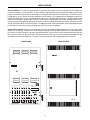
INTRODUCTION
The IWA 250 In-Wall Powered Mixer provides an 8 input/2 output mixer plus
emergency page interrupt, a 9-band graphic equalizer, and a 250 Watt power
amplifier with outputs for standard and distributed speaker systems. Optional
VCA remote control cards may be added for controlling mixer input/output
levels. Designed for in-wall or surface mounting, with integral security cover,
the IWA250 is UL/C-UL listed and is covered by a five-year warranty.
Warranty
•
•
•
•
•
•
•
•
•
•
•
•
•
•
•
•
•
six balanced microphone/line level mixer input channels
two balanced/summing line level mixer input channels
high & low tone controls on each mixer input channel
independent main & aux level controls on each channel
trim control & peak indicator on each mic/line input channel
additional balanced line input for emergency page interrupt
main & aux mixer outputs with master level controls
mixer functions provided on screw-driver adjustable controls
optional VCA cards for remote control of input/output levels
9-band graphic equalization integrated at amplifier input
patch points provided for mixer outputs & equalizer input
mixer inputs & outputs on front panel plug-in barrier strips
output taps for standard and distributed speaker systems
+48 Volt phantom power selectable for microphone inputs
"in-wall" or "surface-mount" chassis with security cover
UL and C-UL listed
covered by Biamp Systems' five-year warranty
IMPORTANT SAFETY INFORMATION
Read these instructions.
Do not install near any heat sources such as radiators, heat
registers, stoves, or other apparatus (including amplifiers) that
produce heat.
Keep these instructions.
Heed all warnings.
Do not defeat the safety purpose of the polarized or groundingtype plug. A polarized plug has two blades with one wider than
the other. A grounding type plug has two blades and a third
grounding prong. The wide blade or the third prong are provided
for your safety. When the provided plug does not fit into your
outlet, consult an electrician for replacement of the obsolete
outlet.
Follow all instructions.
Do not use this apparatus near water.
Clean only with a dry cloth.
Do not block any of the ventilation openings.
Protect the power cord from being walked on or pinched
particularly at plugs, convenience receptacles, and the point
where they exit from the apparatus.
Install in accordance with the manufacturers instructions.
WARNING - To reduce the risk of electric shock, do not expose
this apparatus to rain or moisture.
Refer all servicing to qualified service personnel. Servicing is
required when the apparatus has been damaged in any way,
such as power-supply cord or plug is damaged, liquid has been
spilled or objects have fallen into the apparatus, the apparatus
has been exposed to rain or moisture, does not operate
normally, or has been dropped.
Unplug this apparatus during lightning storms or when unused
for long periods of time.
Apparatus shall not be exposed to dripping or splashing and no
objects filled with liquids, such as vases, shall be placed on the
apparatus.
Explanation of safety related markings and symbols which appear on the outside of the apparatus.
Lightning Bolt: Hazardous Live voltages present when this unit is in operation. Do not touch terminals marked with this
symbol while the unit is connected to live power.
Exclamation Point: Replace components (i.e. fuses) only with the values specified by the manufacturer. Failure to do so will
compromise safe operation of this unit.
CAUTION
CAUTION: Opening the unit enclosure will place operator at risk of injury due to electric shock.
RISK OF ELECTRICAL SHOCK.
DO NOT OPEN.
1
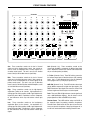
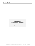
FRONT PANEL FEATURES
channels
1
2
3
4
5
6
7
8
aux
aux
aux
aux
aux
aux
aux
aux
C
UL
R
power
~
120V
60Hz
900 Watts
US
LISTED
52SJ
main equalizer
+15
max
min
max
min
main
max
min
main
max
min
main
max
min
main
max
min
main
max
min
main
main
+15
max
min
main
-15
-15
63
max
min
max
min
high
max
min
high
max
min
high
max
min
high
max
min
high
max
min
high
250
500
1k
2k
4k
8k
16k
max
min
high
125
high
IWA 250 Powered Mixer
+12
-12
low
gain
gain
+12
-12
low
+12
-12
+12
-12
low
+12
-12
+12
-12
low
+12
-12
+12
-12
low
+12
-12
gain
gain
gain
low
+12
-12
mic
line
peak
peak
mic
line
mic
line
peak
mic
line
peak
peak
aux
out
peak
peak
main
out
L / R Sum
ON
ON
20dB Pad
mic
line
max
min
main
L / R Sum
mic
+12
-12
HPF
OFF
ON
AUTO
MANUAL
OVERRIDE
aux
gain
OFF
OFF
line
+12
-12
low
+12
-12
+12
-12
low
+12
-12
+12
-12
OFF
OFF
ON
ON
20dB Pad
peak
min
max
min
max
min
2
3
Phantom Power
4
5
inputs
OFF
OFF
Phantom Power
OFF
OFF
OFF
OFF
1
6
L R
7
8
override
input
aux
out
main
out
common
main EQ in
main out
S
L R
max
active
peak
Phantom Power
Aux: These screw-driver controls set the level of channel
signals sent to the Aux Out master control. Aux controls are
used to create an independent mix of channel signals for a
secondary sound system. This mix is sent (via the Aux Out
master control) to the Aux Out connector (see below).
Gain (Channels 1~6): These screw-driver controls set the
channel gain (0~60dB) to compensate for different input signal
levels. Adjust these controls so the channel Peak indictors flash
only on occasional peaks (see below).
L / R Sum (Channels 7 & 8): These DIP switches convert the
the balanced mono inputs to unbalanced stereo (L/R) summing
inputs. Use L / R Sum whenever input is from an unbalanced
stereo program source (i.e. CD player, tape deck, etc.).
Main: These screw-driver controls set the level of channel
signals sent to the Main Out master control. Main controls are
used to create an independent mix of channel signals for the
primary sound system. This mix is sent (via the Main Out
master control) to the Main Equalizer and Main Amplifier, as well
as to the Main Out connector (see below).
20dB Pad (Channels 7 & 8): These DIP switches reduce input
gain by 20dB to compensate for higher level input signals. Use
20dB Pad whenever input signal levels cause the channel Peak
indicator to light more often than just on occasional peaks.
High: These screw-driver controls set the high-frequency
equalization (Treble) for the channels. High equalization is a
shelving type filter, which provides ±12dB of gain adjustment for
frequencies above 10kHz. Equalization is used to compensate
for tonal differences which may exist between various input
signals.
Peak: These red LEDs will light whenever channel signal levels
reach +10dB (8dB below clipping). Use this feature to aid in
proper adjustment of Gain and 20dB Pad (see above).
Phantom Power: These DIP switches assign +48 Volt DC to
the respective inputs for powering condenser microphones.
Phantom Power should remain off when input is from line-level
sources or dynamic microphones. Always turn AC power off, or
turn all level controls down, before switching Phantom Power.
Low: These screw-driver controls set the low-frequency
equalization (Bass) for the channels. Low equalization is a
shelving type filter, which provides ±12dB of gain adjustment for
frequencies below 50Hz. Equalization is used to compensate
for tonal differences which may exist between various input
signals.
2
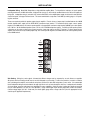
FRONT PANEL FEATURES
output, using a common ground (d). To access unbalanced
Main Out from the mixer (to feed recorders, auxiliary amps, etc.)
wire high to "Main Out" and ground to (d), without removing the
jumper wire. NOTE: If the jumper is removed, the main output
and equalizer input are separated (no signal passes between
them). Remote level control is optional (see pg. 8).
Inputs (Channels 1~6): These plug-in barrier strips provide
mic/line input to Channels 1~6. These inputs accept signals
from balanced low-impedance microphones or from balanced
(or unbalanced) line-level sources. Balanced input (Mic or Line)
is wired high to (+), low to (-), and ground to (d). Unbalanced
Line input is wired high to (+), and ground to both (-) and (d).
Phantom Power (+48V) is selectable per input (see above) and
remote level control is optional (see pg. 8).
Aux Out: The Aux Out screw-driver control sets the overall
level of signals sent (from channel Aux controls) to the Aux Out
connector. The Aux Out connector is a plug-in barrier strip,
which provides a balanced line-level output for feeding external
equipment (recorders, auxiliary amplifiers, etc.).
For
unbalanced output, wire high to (+) and ground to (d), leaving () un-connected. Remote level control is optional (see pg. 8).
Inputs (Channels 7 & 8): These plug-in barrier strips provide
line level input to Channels 7 & 8. These inputs accept mono
(balanced or unbalanced) or stereo (unbalanced) signals from
line-level sources (see L/R Sum above). Balanced mono input
is wired high to (+), low to (-), and ground to (d). Unbalanced
mono input is wired high to (+), and ground to both (-) and (d).
Unbalanced stereo input is wired left high to (L), right high to
(R), and both grounds to (d). Stereo signals are summed
together into a mono signal at this input. Two independent
mono signals may be connected here (wired to left & right
respectively), which will be summed together providing common
channel equalization and level controls. Remote level control is
optional (see pg. 8).
HPF: This DIP switch enables a high-pass filter (12dB/octave
@ 125Hz) which reduces unnecessary low-frequency signals.
Enable HPF whenever the 70V or 25V outputs are being used,
or in any 'speech only' applications.
Override: This DIP switch determines whether the Override
Input will trigger muting of all other input signals automatically
(via signal presence) or manually (via external switch).
Override Input: This plug-in barrier strip provides the line level
override input. This inputs accepts mono (balanced or
unbalanced) signals from line-level sources. Balanced input is
wired high to (+), low to (-), and ground to (d). Unbalanced
input is wired high to (+), and ground to both (-) and (d). The
Override Input channel includes the same Main & Aux level
controls as all other inputs. However, there is no input Gain
control. Therefore, input level must be adjusted at the override
source. For best performance, adjust the override source level
so the channel Peak indictor flashes only on occasional peaks
(see Peak above). The Override Input can trigger muting of all
other input signals either manually (via external switch) or
automatically (via signal presence), regardless of Main or Aux
level settings (see Override below). For manual muting (as from
a push-to-talk paging microphone) the switch is wired across the
Override Input (S) and (d) terminals. For automatic muting (as
from telephone paging), an Override Sensitivity adjustment must
be made (see pg. 8). The green Active LED indicator will
remain lit during either form of Override muting.
Main Equalizer: This 9-band graphic equalizer adjusts the
frequency response (tonal balance) of signals sent to the Main
Amplifier. Each control provides ±15dB boost/cut at the
designated center frequency. From the factory, the Main
Equalizer receives signal from the mixer Main Out. However,
the Main Equalizer may instead be wired to receive signal from
another source (see Main Out above). Do not boost frequencies
below 250Hz whenever the 70V or 25V outputs are being used.
Power Switch: This switch applies power to the unit. Caution:
complete all connections & installation before turning power on.
Power Indicator (not shown): This green LED lights when
power is applied to the IWA 250.
Temp/Fault Indicator (not shown): This red LED indicates
over-temperature and output fault conditions for the amplifier.
When the LED remains lit, the amplifier has an overtemperature condition. When the LED is flashing, the amplifier
has an output fault condition. Either condition will temporarily
de-activate the amplifier, causing the Signal/Peak LED to turn
off as well. The amplifier will attempt to self-reset once the overtemperature or output fault condition is resolved.
Main Out: The Main Out screw-driver control sets the overall
level of signals sent (from channel Main controls) to the Main
Out connector. The Main Out connector is a plug-in barrier
strip, which provides a balanced line-level output for feeding
external equipment (recorders, auxiliary amplifiers, etc.). For
unbalanced output, wire high to (+) and ground to (d), leaving () un-connected. An additional plug-in barrier strip connector (to
the right of Main Out) provides unbalanced access to the mixer
Main Out, and to the Main Equalizer input. From the factory, a
jumper wire between "Main Out" and "Main EQ In" routes signal
from the Main Out control to the Main Equalizer and the Main
Amplifier. Signal processing may be inserted between the mixer
and the equalizer by first removing the jumper wire, then wiring
"Main Out" to processor input and "main EQ In" to processor
Signal/Clip Indicator (not shown): This 2-color LED indicates
the signal level for the amplifier. When the LED is green, the
amplifier has signal (above -30dB). When the LED is red, the
amplifier signal is clipping (max. power). CAUTION: Signal
levels should be adjusted to avoid clipping. Clipping can cause
distortion, over-temperature conditions, and even loudspeaker
damage. NOTE: Signal/Peak indicators will turn off during
Temp/Fault conditions (see Temp/Fault Indicator above).
3
INSTALLATION
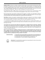
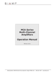
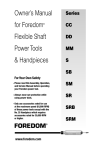
Backbox Installation: Backboxes are available for mounting the IWA 250 chassis in the wall, flush with the finished wall surface ("IWB" In Wall Box), or for mounting on the surface of the wall, with a 4" projection ("SMB" - Surface Mount Box). The mounting location should
be capable of supporting a weight of at least 75 pounds. Surface mounted units ("SMB") should be located near a dedicated AC power
source, capable of providing the required power for the unit being installed. When flush mounted ("IWB"), the front surface of the backbox
must be flush with the finished surface. Failure to do so may cause improper fit of the chassis (or security cover).
Either IWA250 backbox ("IWB" or "SMB") should be connected to electrical service (15 Amp max.) by a licensed electrician, to ensure
compliance with local electrical code. Cables should route through appropriate conduit, raceway, or service entrance cable fitting.
Mount the backbox with the internal cable tray assembly located on the right side. The "IWB" can be mounted between standard 16"
center studs, using the six mounting holes on each side of the box. The "SMB" can be mounted onto standard 16" center studs, using the
four outer-most "keyhole" slots, or onto other suitable surfaces, using the six inner-most "keyhole" slots.
Wire Routing: Wiring that carries signals of dramatically different voltages must be separated by as much distance as possible.
Microphone and line level wiring should never be run with loudspeaker or power wiring. To reduce the potential of crosstalk or oscillations
that could damage the amplifier, never bundle the microphone and line level cables with loudspeaker or power cables.
It is recommended that all loudspeaker wiring enter the backbox at the upper right "knock-out", and route through the cable tray. It is
recommended that wiring for the microphone and line inputs should enter the backbox at the lower right "knock-out", and route under the
bottom edge of the chassis.
The microphone and line level inputs require shielded wire for proper operation. Loudspeaker wiring may be unshielded. Loudspeaker
wire should be of a heavy gauge, to prevent cable losses from degrading the system capabilities. Cable runs using 14 gauge wire should
not exceed 90 feet (for 8 ohm operation) or 45 feet (for 4 ohm operation). Longer cable lengths require heavier gauge cable (smaller wire
number). Constant voltage outputs (70V and 25V) can tolerate lighter gauge cables or longer cable runs (check an appropriate line loss
chart for specific application requirements).
NOTE: AC power should enter the backbox at the bottom left "knock-out" (a standard AC duplex outlet, with enclosure and
cover, is provided). For proper system grounding, the duplex outlet ground, enclosure, backbox, and conduit or raceway must
be bonded together and connected to earth ground. For safety and conformance to codes, this bonding of all metal surfaces
should be performed by a qualified electrician during installation of the backbox.
Back-Box Grounding:
1)
2)
3)
4)
The back-box must be electrically bonded to the ground conductor of the incoming power cable.
Ground to the box should be bonded to the stud provided in the cable tray inside the back-box.
Grounding shall be made with minimum #18 AWG wire, preferably green in color.
Grounding shall be in accordance with NEC and all applicable wiring codes.
Safety Ground: This symbol identifies the appropriate back-box grounding stud, located on the lower portion of
the cable tray at the bottom right of the back-box.
4
INSTALLATION
SMB
(Surface Mount Box)
IWB
(In Wall Box)
5
INSTALLATION
Chassis Installation: The chassis front panel includes two male hinges, which must be secured to the right side-rail of the backbox (use
the screws, lock-washers, and nuts provided). Be sure to install the male hinges with the pin pointing up and towards the inside of the
backbox. The chassis front panel (with two female hinges on its right side) is then lowered onto the male hinges. This allows the chassis
to swing open for access to internal connections, modifications, and for servicing. It is recommended that all loudspeaker wiring enter the
backbox at the upper right "knock-out", and route through the cable tray. It is recommended that wiring for the microphone and line inputs
should enter the backbox at the lower right "knock-out", and route under the bottom edge of the chassis. Mounting hardware for the
security cover must be installed before proceeding (see below). Install the two speed nuts (provided with chassis) in the holes on the left
side-rail of the backbox, directly across from the hinges. Two tapping screws with washers (provided with chassis) install through the holes
in the left side of the chassis front panel (into the speed nuts) to secure the chassis to the backbox.
Security Cover Installation: Before the chassis front panel is secured to the backbox, mounting hardware for the security cover must be
installed. The security cover is attached to the chassis front panel using four stand-offs (provided with chassis). First, the stand-offs must
be secured to the chassis front panel, using four screws with lock-washers. Be sure to use the chassis front panel holes which align with
the holes in the security cover. Once the chassis is secured to the backbox, the security cover is then secured to the four stand-offs, using
the remaining four screws with lock-washers. The security cover also includes keys for the locking/hinged control access panel.
SECURITY COVER
CHASSIS FRONT
IWA 250 Powered Mixer
temp / fault
CAUTION
RISK OF ELECTRICAL SHOCK.
DO NOT OPEN.
amplifier
signal / clip
power
channels
1
2
3
4
5
6
7
8
aux
aux
aux
aux
aux
aux
aux
aux
C
UL
R
power
~
120V
60Hz
900 Watts
US
LISTED
52SJ
main equalizer
+15
max
min
max
min
main
max
min
main
max
min
main
max
min
main
max
min
main
max
min
main
+15
max
min
main
main
-15
-15
63
min
max
min
+15
-15
high
max
min
+15
-15
high
max
min
+15
-15
high
max
min
+15
-15
high
max
min
+15
-15
high
max
min
+15
-15
high
max
min
+15
-15
high
125
250
500
1k
2k
4k
8k
16k
max
high
IWA 250 Powered Mixer
-15
low
low
+15
-15
+15
-15
gain
low
+15
-15
gain
low
low
+15
-15
gain
+15
-15
gain
low
+15
-15
gain
low
+15
-15
mic
line
mic
line
mic
line
mic
line
line
max
min
aux
out
main
L / R Sum
mic
+15
-15
HPF
OFF
ON
MANUAL
AUTO
OVERRIDE
aux
gain
OFF
OFF
line
+15
low
mic
peak
peak
peak
peak
peak
1
2
3
4
5
6
peak
OFF
OFF
ON
ON
20dB Pad
peak
min
max
min
max
min
S
Phantom Power
inputs
OFF
OFF
OFF
OFF
OFF
OFF
Phantom Power
L R
L R
7
8
max
active
peak
override
input
aux
out
main
out
common
main EQ in
main out
peak
20dB Pad
main
out
L / R Sum
ON
ON
Phantom Power
6
INSTALLATION
Loudspeaker Wiring: Model IWA 250 provides a single 250 Watt amplifier (Main). To help offset the inductance of certain speaker
matching transformers, the IWA 250 includes a high-pass filter (see pg. 3), which must be enabled whenever the 70V or 25V outputs are
being used. Loudspeaker wiring is connected to the screw-terminal block on the amplifier/power supply circuit board, located inside the
chassis front panel, at the upper left-hand corner. This screw-terminal block accept wires of #12 AWG (or smaller) gauge, or 1/4" spadelug wire connectors.
These screw terminals provide the speaker outputs from the amplifier. From the factory, a jumper strap is installed betweem the 4 OHM
terminal (amplifier direct output) and the XFMR INPUT (transformer input) terminal. For transformer (xfmr) output, connect speaker
negative to the COM terminal, and connect speaker positive to the appropriate transformer output terminal (8 OHM for an 8 ohm speaker
load; 70V for a 70 Volt distributed speaker system; 25V for a 25 Volt distributed speaker system). For 'balanced' 25V speaker systems,
connections are the same as above, plus a ground connection (center-tap) made to the 25V C.T. terminal. For direct output from the
amplifier, first remove the factory installed jumper strap, then connect speaker negative to the GND terminal, and connect speaker positive
to the 4 OHM terminal.
8
OHM
70V
25V
25V
C.T.
COM
XFMR
INPUT
4
OHM
GND
Wire Routing: Wiring that carries signals of dramatically different voltages must be separated by as much distance as possible.
Microphone and line level wiring should never be run with loudspeaker or power wiring. To reduce the potential of crosstalk or oscillations
that could damage the amplifier, never bundle the microphone and line level cables with loudspeaker or power cables. It is recommended
that all loudspeaker wiring enter the backbox at the upper right "knock-out", and route through the cable tray. Loudspeaker wire should be
of a heavy gauge, to prevent cable losses from degrading the system capabilities. Cable runs using 14 gauge wire should not exceed 90
feet (for 8 ohm operation) or 45 feet (for 4 ohm operation). Longer cable lengths require heavier gauge cable (smaller wire number).
Constant voltage outputs (25, 70.7, or 100 volts) can tolerate lighter gauge cables or longer cable runs (check an appropriate line loss
chart for specific application requirements).
7
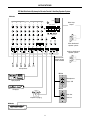
REMOTE CONTROL
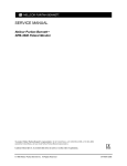
Remote Control: Remote level control is available as a user installed option. It can be added selectively to any of the Input Channels 1~8,
as well as to the Main Out and the Aux Out. Remote control capability is added by installing VCA Cards onto the mixer circuit board (see
diagram on next page). CAUTION: Turn off and/or dis-connect AC power before performing any modifications.
To install VCA Cards, first remove the jumper wires (between OUT and IN) on the respective channels/outputs of the mixer circuit board.
Then install the two plastic support/guides (provided with each VCA Card) into the holes provided on the respective channels/outputs of the
mixer circuit board (support/guides must be properly oriented to accept VCA Card). Once the support/guides are in place, slide the VCA
Cards into the support/guides, making sure all pins on the VCA card slide fully into the corresponding holes in the mixer circuit board.
Once the VCA Cards have been installed, remote controls may be wired up to 2000 feet away, using 2-conductor shielded cable. Controls
may be any 5k~50kΩ linear taper potentiometer and/or switch to provide adjustment and/or muting of the level. Potentiometers are wired
with high-side to "+10V", low-side to "d", and wiper to "C". The wiper of one potentiometer may be wired to the "C" terminal on multiple VCA
Cards, allowing control of a group of signals from a single potentiometer. Switches simply connect (or disconnect) "+10V" to "C", and do not
require a ground (‘d’) connection. A combination of potentiometer and switch may be used, with the switch in line with either the "C" or
"+10V" connection. NOTE: When a VCA Card is installed, but no control is connected, signal will not pass. To avoid this circumstance, a
jumper wire may be temporarily connected between "+10V" and "C". Additionally, if VCA Cards are removed, jumper wires must be reinstalled between OUT and IN on the respective channels/outputs of the mixer circuit board, before signal can pass.
C +10V
VCA
card
Override Sensitivity: The IWA 250 Override Input can trigger muting of all other input signals automatically (see Override Input on pg. 3).
For automatic muting (as from telephone paging), an Override Sensitivity adjustment should be made (see diagram on next page). Once
Override Input settings are made, Override Sensitivity may be adjusted for proper muting sensitivity. Override Sensitivity should be adjusted
so that muting is easily triggered by Override Input (paging) signals, but not by ambient or background noises on the paging line. The
Override Input Active indicator will remain lit during muting.
8
REMOTE CONTROL
IN
OUT
GND
+10V
+12V
-12V
MAX
MIN
OVERRIDE
SENSITIVITY
AUX
IN
OUT
GND
+10V
+12V
-12V
MAIN
-12V
+12V
+10V
GND
OUT
IN
CH 8
-12V
+12V
+10V
GND
OUT
IN
CH 7
-12V
+12V
+10V
GND
OUT
IN
CH 6
-12V
+12V
+10V
GND
OUT
IN
CH 5
-12V
+12V
+10V
GND
OUT
IN
CH 4
-12V
+12V
+10V
GND
OUT
IN
CH 3
-12V
+12V
+10V
GND
OUT
IN
CH 2
-12V
+12V
+10V
GND
OUT
IN
CH 1
Mixer Circuit Board
9
APPLICATIONS
250 Watt Distributed System plus Hearing Assistance & Recording Outputs
IWA 250
channels
1
2
3
4
5
6
7
8
aux
aux
aux
aux
aux
aux
aux
aux
C
UL
R
power
~
120V
60Hz
900 Watts
US
LISTED
52SJ
Main Amp.
output
main equalizer
+15
min
max
min
max
min
main
max
min
max
min
main
max
min
max
min
main
max
min
max
min
main
max
min
max
min
main
max
min
max
min
main
max
min
max
min
main
+15
max
main
-15
-15
63
min
high
high
high
high
high
high
high
125
250
500
1k
2k
4k
8k
16k
max
high
IWA 250 Powered Mixer
+15
-15
low
+15
-15
low
+15
-15
gain
+15
-15
low
+15
-15
gain
+15
-15
low
+15
-15
+15
-15
low
+15
-15
gain
low
+15
-15
mic
line
mic
line
mic
line
mic
line
mic
line
max
min
aux
out
main
OFF
OFF
mic
+15
-15
HPF
OFF
ON
AUTO
MANUAL
OVERRIDE
aux
gain
L / R Sum
line
+15
-15
low
+15
-15
gain
+15
-15
low
+15
-15
gain
+15
-15
peak
peak
peak
peak
peak
1
2
3
4
5
6
peak
OFF
OFF
ON
ON
20dB Pad
min
max
min
max
min
S
Phantom Power
inputs
OFF
OFF
OFF
OFF
OFF
OFF
Phantom Power
L R
L R
7
8
max
active
peak
peak
override
input
aux
out
main
out
common
main EQ in
main out
peak
ON
ON
20dB Pad
main
out
L / R Sum
Phantom Power
microphones
Main distributed
speaker system
tape playback
COMPACT
1
DIGITAL AUDIO
2:50
CD player
mic
preamp
paging microphone
tape recorder
hearing assistance system
10
APPLICATIONS
250 Watt Distributed System plus Remote Control & Auxiliary Speaker System
IWA 250
channels
1
2
3
4
5
6
7
8
aux
aux
aux
aux
aux
aux
aux
aux
C
UL
R
power
~
120V
60Hz
900 Watts
US
LISTED
52SJ
Main Amp.
output
main equalizer
+15
min
max
min
max
min
main
max
min
max
min
main
max
min
max
min
main
max
min
max
min
main
max
min
max
min
main
max
min
max
min
main
max
min
max
min
main
+15
max
main
-15
-15
63
min
high
high
high
high
high
high
high
125
250
500
1k
2k
4k
8k
16k
max
high
IWA 250 Powered Mixer
+15
-15
low
+15
-15
low
+15
-15
gain
+15
-15
low
+15
-15
gain
+15
-15
low
+15
-15
+15
-15
low
+15
-15
gain
low
+15
-15
mic
line
mic
line
mic
line
mic
line
mic
line
max
min
aux
out
main
OFF
OFF
mic
+15
-15
HPF
OFF
ON
AUTO
MANUAL
OVERRIDE
aux
gain
L / R Sum
line
+15
-15
low
+15
-15
gain
+15
-15
low
+15
-15
gain
+15
-15
peak
peak
peak
peak
peak
1
2
3
4
5
6
peak
OFF
OFF
ON
ON
20dB Pad
min
max
min
max
peak
S
Phantom Power
inputs
OFF
OFF
OFF
OFF
OFF
OFF
Phantom Power
L R
L R
7
8
Main distributed
speaker system
max
min
active
peak
override
input
aux
out
main
out
common
main EQ in
main out
peak
ON
ON
20dB Pad
main
out
L / R Sum
Auxiliary distributed
speaker system
Phantom Power
optional VCA
remote control
cards installed
microphones
RP-L2
Microphones
tape playback
Tape / CD
RP-L2
COMPACT
1
DIGITAL AUDIO
2:50
RP-L2
CD player
Main Out
Aux Out
telephone paging
RP-L2
MPA250
MPA250
on
signal
peak
temp
fault
11
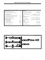
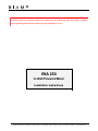
SPECIFICATIONS & BLOCK DIAGRAM
Continuous Power (4 ohm direct & transformer outputs):
Equalization:
250 watts
Signal-to-Noise Ratio (20Hz~20kHz):
referenced to 250 watts into 4 ohm direct output
> 90dB
Total Harmonic Distortion:
low-frequency input channel EQ
±12dB @ 50Hz
high-frequency input channel EQ
±12dB @ 10kHz
±15dB @ 64Hz, 125Hz, 250Hz,
9-band graphic output EQ
20Hz~20kHz @ 250 watts into 4 ohm direct output
< 0.2%
100Hz~15kHz @ 250 watts at transformer outputs
< 1.0%
500Hz, 1kHz, 2kHz, 4kHz, 8kHz, 16kHz
Dimensions (H x W x D):
Intermodulation Distortion (SMPTE):
< 0.35%
security cover
28.6" x 16.25" x 0.9" (726x413x23mm)
Frequency Response (20Hz~20kHz):
+0/-1dB
in-wall back-box
26.6" x 14.25" x 4" (676x362x102mm)
surface-mount back-box
28.6" x 16.25" x 4" (726x413x102mm)
Input / Output Impedance:
balanced mic/line inputs
600 ohms
balanced line-level inputs
20k ohms
chassis + security cover
unbalanced main & aux outputs
200 ohms
in-wall back-box
< 14 lbs. (6.35kg)
unbalanced equalizer input
10k ohms
surface-mount back-box
< 17 lbs. (7.71kg)
Weight:
< 34 lbs. (15.42kg)
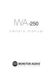
IWA250 block diagram
Input Channels 1 thru 6
Peak LED
+
Main
Level
-
Phantom
Power
Preamp/
Gain
High &
Low EQ
Opt. VCA
Aux
Level
GND
Main Output Section
Σ
Input Channels 7 & 8
+
L
-
R
9-band
Graphic
EQ
Main
Level
Peak LED
Main
Level
Balanced/
Summing
Phantom
Power
Preamp/
Pad
High &
Low EQ
Opt. VCA
Aux
Level
GND
Aux Output Section
Σ
Override Input
Peak LED
+
-
Opt.
VCA
Main Out
Preamp/
Gain
GND
Emer.
Page
Interrupt
Main
Level
Aux
Level
Priority
12
Opt.
VCA
Aux
Level
Aux Out
4 Ohms
Output
XFMR
8 Ohms
70V
25V
Com
WARRANTY
BIAMP SYSTEMS IS PLEASED TO EXTEND THE FOLLOWING 5-YEAR LIMITED WARRANTY TO THE
ORIGINAL PURCHASER OF THE PROFESSIONAL SOUND EQUIPMENT DESCRIBED IN THIS MANUAL
1. BIAMP Systems warrants to the original purchaser of new
products that the product will be free from defects in material
and workmanship for a period of 5 YEARS from the date of
purchase from an authorized BIAMP Systems dealer, subject to
the terms and conditions set forth below.
2. If you notify BIAMP during the warranty period that a BIAMP
Systems product fails to comply with the warranty, BIAMP
Systems will repair or replace, at BIAMP Systems' option, the
nonconforming product. As a condition to receiving the benefits
of this warranty, you must provide BIAMP Systems with
documentation that establishes that you were the original
purchaser of the products. Such evidence may consist of your
sales receipt from an authorized BIAMP Systems dealer.
Transportation and insurance charges to and from the BIAMP
Systems factory for warranty service shall be your responsibility.
3. This warranty will be VOID if the serial number has been
removed or defaced; or if the product has been altered,
subjected to damage, abuse or rental usage, repaired by any
person not authorized by BIAMP Systems to make repairs; or
installed in any manner that does not comply with BIAMP
Systems' recommendations.
4. Electro-mechanical fans, electrolytic capacitors, and normal
wear and tear of items such as paint, knobs, handles, and
covers are not covered under this warranty.
5.
THIS WARRANTY IS IN LIEU OF ALL OTHER
WARRANTIES, EXPRESS OR IMPLIED. BIAMP SYSTEMS
DISCLAIMS ALL OTHER WARRANTIES, EXPRESS OR
IMPLIED, INCLUDING, BUT NOT LIMITED TO, IMPLIED
WARRANTIES OF MERCHANTABILITY AND FITNESS FOR A
PARTICULAR PURPOSE.
6. The remedies set forth herein shall be the purchaser's sole
and exclusive remedies with respect to any defective product.
7. No agent, employee, distributor or dealer of Biamp Systems
is authorized to modify this warranty or to make additional
warranties on behalf of Biamp Systems.
statements,
representations or warranties made by any dealer do not
constitute warranties by Biamp Systems. Biamp Systems shall
not be responsible or liable for any statement, representation or
warranty made by any dealer or other person.
8. No action for breach of this warranty may be commenced
more than one year after the expiration of this warranty.
9. BIAMP SYSTEMS SHALL NOT BE LIABLE FOR SPECIAL,
INDIRECT, INCIDENTAL, OR CONSEQUENTIAL DAMAGES,
INCLUDING LOST PROFITS OR LOSS OF USE ARISING
OUT OF THE PURCHASE, SALE, OR USE OF THE
PRODUCTS, EVEN IF BIAMP SYSTEMS WAS ADVISED OF
THE POSSIBILITY OF SUCH DAMAGES.
Biamp Systems
9300 S.W. Gemini Drive
Beaverton, Oregon 97008
(503) 641-7287
585.0175.90A