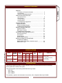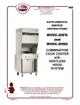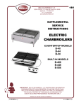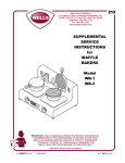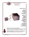
1
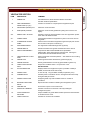
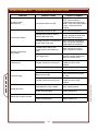
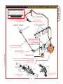
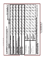
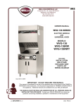
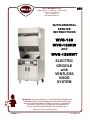
502
WELLS BLOOMFIELD, LLC
2 ERIK CIRCLE, P. O. Box 280 Verdi, NV 89439
telephone: 775-689-5707
fax: 775-689-5976
www.wellsbloomfield.com
SUPPLEMENTAL
SERVICE
INSTRUCTIONS
WVG-136
WVG-136RW
and
WVG-136RWT
ELECTRIC
GRIDDLE
with
VENTLESS
HOOD
SYSTEM
IMPORTANT: WELLS BLOOMFIELD, LLC PROPRIETARY INFORMATION.
DISSEMINATION OF THIS INFORMATION TO ANYONE OTHER THAN
WELLS AUTHORIZED SERVICE AGENTS IS STRICTLY PROHIBITED.
TECHNICAL CONTENT OF THIS MANUAL IS DESIGNED FOR
USE BY QUALIFIED PROFESSIONAL TECHNICIANS ONLY.
PRINTED IN UNITED STATES OF AMERICA
p/n SV502 Rev.(-)
S502
080516 cps
PRECAUTIONS AND GENERAL INFORMATION
GENERAL
WARNING:
RISK OF
INJURY
Installation procedures must
be performed by a qualified
technician with full knowledge
of all applicable electrical and
plumbing codes. Failure can
result in personal injury and
property damage.
WARNING:
ELECTRIC
SHOCK HAZARD
All servicing requiring access
to non-insulated electrical
components must be
performed by a qualified
technician.
Some procedures involve
exposed live circuits. Use all
due caution to avoid contact
with live electric circuits.
Failure to follow this warning
can result in severe electrical
shock.
This appliance is intended for use in commercial establishments
only.
This appliance is intended to prepare food for human consumption.
No other use is recommended or authorized by the manufacturer or its
agents.
Operators of this appliance must be familiar with the appliance use,
limitations and associated restrictions. Operating instructions must be
read and understood by all persons using or installing this appliance.
Cleanliness of this appliance is essential to good sanitation. Read and
follow all included cleaning instructions and schedules to ensure the
safety of the food product.
Disconnect this appliance from electrical power before performing any
maintenance or servicing.
DO NOT splash or pour water on, in or over any controls, control
panel or wiring.
The technical content of this manual, including any wiring diagrams,
schematics, parts breakdown illustrations and/or adjustment
procedures, is intended for use by qualified technical personnel.
Any procedure which requires the use of tools must be performed by a
qualified technician. All service to the fire suppression system must be
performed by an authorized Ansul® agency.
This appliance is made in the USA. Unless otherwise noted, this
appliance has American sizes on all hardware.
IMPORTANT INSTALLATION NOTE:
CAUTION:
RISK OF
DAMAGE
This installation requires a minimum ceiling height of 96" in order to
maintain adequate airflow.
SV502 SvcManual WVG-136(RW)
DO NOT connect or energize
this appliance until all
installation instructions are
read and followed. Damage to
the appliance will result if
these instructions are not
followed.
6” clearance is required from back and sides of the appliance to any
combustible or non-combustible surface.
xi
GENERAL
Precautions & General Information …………….…………
Specifications ..……………………………...................…..
Features & Operating Controls …………………………….
VENTILATOR HOOD SECTION
Operational Notes ...........................................................
Filter System ...................................................................
Vacuum System ..............................................................
Ansul® System ...............................................................
Troubleshooting Suggestions ………………………………
GRIDDLE SECTION
Operational Notes ..............................................................
Element Clamping Diagram ..............................................
Troubleshooting Suggestions ...........................................
DRAWER WARMER SECTION
Operational Notes ..............................................................
RWT-Style Controller ........................................................
Troubleshooting Suggestions ...........................................
EXPLODED VIEWS AND PARTS LISTS
Ansul® Components .........................................................
Hood Section ....................................................................
Griddle Section ................................................................
Drawer Warmer Section ...................................................
WIRING SCHEMATICS & DIAGRAMS .................................
OTHER DOCUMENTS
Material Safety Data Sheet—Ansulex Low pH .................
Maintenance Logs ............................................................
GENERAL
TABLE OF CONTENTS
xi
1
2
8
10
11
12
14
16
19
19
20
21
22
23
24
26
28
30
36
38
SV502 SvcManual WVG-136(RW)
SPECIFICATIONS
MODEL
WVG-136
WVG-136RW
WVG-136RWT
DRAWER
WARMER
3ø AMPS
VOLTS
60Hz
L2
L3
1ø
AMPS
WATTS
L1
208V
17
29
17
35
7300
240V
20
33
20
40
9500
208V
20
28
20
38
7900
240V
24
33
24
43
10400
NO
YES
DIMENSIONS
30-3/8" Wide
(42-3/8" incl. spacers)
77-1/4" High
35-1/2" Deep
INTRODUCTION
This manual contains information needed to properly service and repair Wells Bloomfield free-standing
electric griddle with ventless hood system.
This manual applies to the following Wells Manufacturing models:
WVG-136
WVG-136RW
WVG-136RWT
For installation, operation and maintenance instructions, refer to Operation Manual p/n 304986.
1
FEATURES & OPERATING CONTROLS
GENERAL
28
28
VENTILATOR CONTROL PANEL
see pages 4 & 5
a15
28
1
56
53
19
16
18
a11
18
16
23
23
GRIDDLE CONTROL PANEL
see pages 4 & 5
22
a10
ANS UL
40
12
IN CASE OF
FIRE
®
41
PULL
HANDLE
TO ACTIVATE
FIRE SUPPRESSION
SYST EM
44
a6
a31
43
8
9
Fig. 1 Ventilator Section Operating Features & Controls
2
38
38
SV502 SvcManual WVG-136(RW)
WARMER CONTROLS
see pages 4 & 5
42
FEATURES & OPERATING CONTROLS (continued)
ITEM
DESCRIPTION
COMMENT
1.
NAMEPLATE
Lists Manufacturer, Model and Serial Number information.
Also lists electrical specifications.
a6.
FIRE SUPPRESSION
AGENT TANK (1.5 gal.)
Container for Ansulex™ Low-pH liquid fire suppression liquid.
8.
ADJUSTABLE (FRONT) LEG
Allows the unit to be leveled.
9.
RIGID (REAR) CASTER
Allows the unit to be easily positioned by lifting the front of the unit
slightly.
a10.
MANUAL PULL STATION
Provides a means of manual activation of the fire suppression system.
PULL ONLY IN CASE OF FIRE!
a11.
FUSIBLE LINKS
Automatically activates fire suppression system in the event of fire on
the griddle.
LOWER REAR ACCESS
PANEL
Allows access to Ansul® fire suppression agent tank (a6) and controls
also access to main power contactor (41).
DISCHARGE NOZZLE
Fire suppression media discharges here (2 places).
16.
GREASE BAFFLE
Extracts and drains most grease and moisture from the air flow.
18.
PRE-FILTER ASSEMBLY
Comprises the PRE-FILTER FRAME and a replaceable
PRE-FILTER. Stops larger particles of grease from reaching the
FILTER PACK for reduced maintenance costs.
19.
HEPA/CHARCOAL FILTER
PACK
Stops most grease and smoke particles. Also assists in some cooking
odor removal.
22.
GREASE CUP
Collects grease/moisture drained from grease trough (23).
23.
GREASE TROUGH
Directs grease/moisture removed by grease baffle to grease cup.
28.
VENTILATOR EXHAUST
DUCT
Exit point for ventilator airflow - on top left rear of unit.
DO NOT BLOCK
STATUS INDICATOR
Displays status of fire suppression system (COCKED - FIRED) If
FIRED, a buzzer will sound continuously.
38.
POWER CORD
6’ cord and cap. Plug for NEMA 15-60R (receptacle by user).
40.
WARMER RELAY
Provides power to roll warmer section. Energized at all times except
during fire safety shut-down.
41.
POWER CONTACTOR
Energizes griddle only while ventilator section is sensed as
operational.
42.
BUILDING FIRE ALARM
RELAY
Reports fire alarm condition to building fire management system.
43.
GROUND LUG
Ground wire of power cord connects here.
44.
INTERLOCK TERMINAL
Provides connection for shut-down control by building fire
management system.
53.
FILTER INTERLOCK
SWITCHES
Proper installation of grease baffle and filter pack close these switches
in ventilator sensor circuit.
56.
VENTILATOR FAN
Provides air movement for ventilation.
12.
a15.
SV502 SvcManual WVG-136(RW)
a31.
3
GENERAL
VENTILATOR SECTION
FEATURES & OPERATING CONTROLS (continued)
GENERAL
V.02
V.03
V.04
V.05
V.06
V.01
Fig. 2 Ventilator Section Controls & Indicator Lights
GRIDDLE
SURFACE
HUMITROL
RACK
GREASE
TROUGH
DRAWER
INSE RT
PAN
GREASE
DRAWER
G.02
G.01
W.03
W.02
RW-STYLE
GRIDDLE
W.01
W.06
RWT-STYLE
OPTIONAL ROLL WARMER
W.05
Fig. 3 Griddle & Warmer Drawer Operating Features & Controls
4
SV502 SvcManual WVG-136(RW)
W.04
FEATURES & OPERATING CONTROLS (continued)
DESCRIPTION
COMMENT
VENTILATOR SECTION CONTROLS
V.01
POWER SWITCH
Energizes blower motor. If, after 10 seconds, proper conditions
are met, appliance is energized.
V.02
POWER ON INDICATOR
GREEN. Glows when POWER switch is ON.
V.03
CHECK FILTERS ALARM
INDICATOR
AMBER. Glows if one or more filters are out of position. Check
all filters and baffles for proper installation.
V.04*
REPLACE PREFILTER
ALARM INDICATOR
AMBER. Glows when PREFILTER is approaching the end of its
service life and must soon be replaced.
V.05*
REPLACE FILTER PACK
ALARM INDICATOR
AMBER. Glows when FILTER PACK is approaching the end of
its service life and must soon be replaced.
V.06*
SERVICE REQUIRED
ALARM INDICATOR
RED. Glows when PREFILTER and/or FILTER PACK has
reached the end of its service life and is too loaded to allow
sufficient air flow. Filter MUST be replaced. Appliance is SHUT
DOWN until expended filters are replaced.
*
See PRECAUTIONS & GENERAL INFORMATION, pages 6 - 8 for special procedures regarding
prefilters and filter packs.
GRIDDLE SECTION CONTROLS
G.01
GRIDDLE TEMPERATURE
CONTROL
Thermostat control of temperature of one griddle half.
G.02
INDICATOR LIGHT
AMBER. Glows when heating element is energized.
OPTIONAL WARMER SECTION CONTROLS
SV502 SvcManual WVG-136(RW)
RW-STYLE
W.01
WARMER TEMPERATURE
CONTROL
Infinite switch control of one warmer drawer.
W.02
POWER ON INDICATOR
AMBER. Glows when associated control is turned ON.
W.03
THERMOMETER
(OPTIONAL )
Shows temperature in warmer drawer. Must be ordered at time
of initial equipment build.
W.04
HUMIDITY CONTROL
Slide control of shutters to control air circulation within the
warmer drawer.
RWT-STYLE
W.05
CONTROL MODULE
Adjust setpoint, view setpoint and actual temperatures.
W.06
WARMER POWER
SWITCH
Energize individual drawer warmer.
5
GENERAL
ITEM
HOOD SECTION - OPERATIONAL NOTES
FAN
WALL OF UNIT
FILTER PA CK
SE AL
FILTER PACK
FILTER PA CK
AIR FLOW
VENTILATOR HOOD
FILTER PA CK
PO SITIO N
SWITCH
HOL DE R CLIP
GRE ASE B AFFLE
PO SITIO N
SWITCH
H OLDER CLIP
CLIPS ONTO
LEDGE
PRE -FILTER
AS SEMB LY
GRE ASE
BA FFL E
GRE ASE
TROUGH
PRE -FILTER
NOTE: AIR FL OW A RRO W
PO INTS AWAY FROM
INSTAL LER WHEN
PRO PERLY INSTA LLE D
FILTER HOOK
R
E
TE
R
FILTER
HOOK
FILTER
RAIL
FILTER
HANDLE
FILTER
FRAME
NOTE: P RE-FILTER IS S ENSE D
AS B EING IN POS ITION BY THE
PRE SSURE DROP A CRO SS IT.
6
SV502 SvcManual WVG-136(RW)
P
IL
-F
HOOD SECTION - OPERATIONAL NOTES (continued)
POWER SWITCH
SV502 SvcManual WVG-136(RW)
INDICATOR LIGHT
When lit, indicates that electrical power is available,
(GREEN) VENTILATOR
and that the power switch (V.01) is turned ON.
POWER ON
INDICATOR LIGHT
(AMBER) CHECK
FILTERS (POSITION)
When lit, indicates that the BAFFLE, PRE-FILTER
and/or FILTER PACK is not in its proper position,
or that an interlock switch is out of adjustment.
Controlled by: Plunger switches position monitors
for Filter Pack and Grease Baffle; and, vacuum
switch S3 for Pre-Filter.
INDICATOR LIGHT
(AMBER) REPLACE
PREFILTER
When lit, indicates that the pre-filter is approaching
the end of its service life.
ALWAYS HAVE A SPARE PRE-FILTER ON
HAND FOR QUICK REPLACEMENT.
Controlled by vacuum switch S1.
INDICATOR LIGHT
(AMBER) REPLACE
FILTER PACK
When lit, indicates that the filter pack is approaching
the end of its service life.
REPLACE FILTER PACK PROMPTLY!
Controlled by vacuum switch S2.
INDICATOR LIGHT
(RED) SERVICE
REQUIRED
Indicates that either the pre-filter or the filter pack is
individually clogged (the individual indicator light
may be lit), or that the the airflow drop across both
filters is critical. As a cost saving measure, always
change a dirty pre-filter first (when lights V.04 &
V.05 are not lit, and red light V.06 is on).
Note: Power to the cooking appliance will be
de-energized whenever this RED “SERVICE
REQUIRED” indicator light is lit. When lit, the air
flow is insufficient to meet appliance vapor capture
levels requirements.
Controlled by vacuum switch S4.
7
VENTILATOR HOOD
Energizes the ventilator section. When all three
filters are sensed as being in their proper position,
and sufficient airflow is proven, the cooking
appliance contactor is energized.
HOOD SECTION - OPERATIONAL NOTES (continued)
WARNING:
FIRE AND HEALTH
HAZARDS
VENTILATOR HOOD
DO NOT bypass or attempt to
bypass the filter placement
interlocks. Operating the
appliance without filters properly
in place will compromise the fire
protection and air filtration
capabilities of this unit.
Serious personal injury and/or
substantial property damage may
result.
NOTICE:
Operating without all filters
properly in place, and/or
operating with filter placement
interlocks defeated will void the
manufacturer’s warranty.
IMPORTANT:
NEVER wash the PREFILTER or
FILTER PACK.This will shut
down the cooking appliance.
(Red “SERVICE REQUIRED”
light will turn ON).
REPLACE PREFILTER and REPLACE FILTER PACK indicator lights
provide a timely warning that a system shut-down is imminent. The
actual time between the indicator light coming on and the loss of
cooking appliance power will depend upon the cooking conditions.
Anytime a dirty PRE-FILTER is replaced, the system airflow will
increase. If the condition of the FILTER PACK is marginal, the
REPLACE FILTER PACK light could then come on. If this happens, a
fresh FILTER PACK must be installed within a reasonably short time.
Loss of airflow through the old filter pack will soon cause a system
shut-down when the airflow falls below minimum vapor capture levels.
KEEP SPARE FILTER PACKS ON HAND.
IMPORTANT: If you decide to “get the most” out of the old filter pack,
and continue to use it until a system shut-down happens, it is advisable
to have a fresh filter pack readily at hand, and have someone available
who is capable of replacing it. Otherwise, you may experience an
extended down time, with consequent associated loss of business.
The manufacturer assumes no liability for loss of business due to
a system shutdown caused by a dirty pre-filter and/or filter pack
(i.e. red SERVICE REQUIRED light is on), when the user fails to
have the proper replacement pre-filter and/or filter pack on hand.
SV502 SvcManual WVG-136(RW)
8
HOOD SECTION - OPERATIONAL NOTES (continued)
FIRE
DAMPER
LABEL
SHUTTER
DAMPER
SUPPORT
FUSIBLE LINK
280ºF
FIRE DAMPER INSTRUCTIONS
1. The FIRE DAMPER is accessible by removing the TOP PANEL
The FIRE DAMPER sets in the DAMPER SUPPORT and may be
removed by lifting straight up.
SV502 SvcManual WVG-136(RW)
2. The FIRE DAMPER normally needs no maintenance. If it
becomes heavily contaminated with dust and/or grease, it must
be replaced.
3. If the FIRE DAMPER malfunctions or if the fusible link releases,
the manufacturer recommends that the entire FIRE DAMPER
ASSEMBLY be replaced.
4. Reinstall the FIRE DAMPER with the “THIS SIDE UP FOR
HORIZONTAL MOUNTING” arrow pointing away from the
BLOWER.
9
IMPORTANT:
Replace the entire fire damper
assembly if the link trips, or if the
damper mechanism becomes
heavily contaminated with dust
and/or grease.
While the fusible link alone may be
replaced, once the damper has
tripped it may no longer function
reliably.
Contact factory for pricing and
availability.
VENTILATOR HOOD
THIS SIDE UP
FOR HORIZONTAL
MOUNTING
THIS
SIDE UP
FOR VERTICAL
MOUNTING
¬ ®
AIR FLOW
ACCESS DOOR
THIS SIDE
HOOD SECTION - FILTER SYSTEM
HOOD ASSEMBLY
(LOOKING UP)
VENTILATOR HOOD
FILTER PACK
POSITION MONITOR
GREASE BAFFLE
POSITION MONITOR
PRE-FILTER
ASSEMBLY
NOTE AIR FLOW ARROWS ON
GREASE BAFFLE, PRE-FILTER
AND FILTER PACK. INSTALL
THESE COMPONENTS SUCH
THAT ARROWS POINT
TOWARD FAN
FILTER
PACK
GREASE
BAFFLE
1. The GREASE BAFFLE separates grease particles and water vapor
from the air stream by the centrifugal force of the air moving through
its inter-leaved baffle plates. Ejecta is collected in the GREASE CUP
through drain holes in the baffle frame and cabinet.
The GREASE BAFFLE POSITION MONITOR plunger switch controls
electric power to the ventilator fan.
NOTE:
The charcoal portion of the
filter pack is an aid in
controlling cooking odors
only. It will not completely
eliminate such odors.
2. The PRE-FILTER is composed of a replaceable media filter and a
filter-retaining gage. The pre-filter captures the bulk of grease vapors.
Pre-filter position is monitored by a vacuum switch, which is in the
control circuit of the cooking appliance contactor.
3. The FILTER PACK is composed of a high-efficiency filter to capture
grease vapors down to a very small particle size; and, an activated
charcoal filter to help control cooking odors.
The FILTER PACK POSITION MONITOR plunger switch is in the
control circuit of the cooking appliance contactor.
10
SV502 SvcManual WVG-136(RW)
NOTE:
Change the pre-filter as
soon as the "REPLACE
PRE-FILTER" indicator
glows in order to extend the
service life of the filter pack.
HOOD SECTION - VACUUM SYSTEM
FAN
PORT A
VS4
PORT A
VS1
VENTILATOR HOOD
PORT B
FAN
PORT C
PORT C
PORT C
VS3
PORT B
PLENUM PORT
(AFTER FILTER PACK)
VS2
SV502 SvcManual WVG-136(RW)
VS2
FILTER PACK ALERT
Will illuminate "REPLACE FILTER PACK"
indicator if pressure drop across the filter
pack exceeds setting.
VS3
PRE-FILTER ALERT
Will illuminate "REPLACE PRE-FILTER"
indicator if pressure drop across the prefilter exceeds setting.
VS4
AIR FLOW MONITOR
Pressure drop must exceed setting before
cooking appliance is energized. As filters
become plugged, airflow decreases.
Beyond the useful life of the filters, air flow
will be insufficient to maintain the required
pressure drop, which will shut-down
ventilator fan and cooking appliance and
illuminate "SERVICE REQUIRED"
indicator.
GREASE
BAFFLE
PREFILTER
SWITCH
VS1
PRESSURE
RISE FROM
FAN
PRESSURE
DROP ACROSS
FILTER PACK
PRE-FILTER POSITION MONITOR
Unit will not function unless a pre-filter
is properly installed, as sensed by the
pressure drop across it. Pressure drop
across the pre-filter must exceed setting
before cooking appliance is energized.
Insufficient pressure drop will illuminate
"CHECK FILTER" indicator.
AMBIENT
PRESSURE
VS1
PRESSURE
DROP ACROSS
BAFFLE
SWITCH FUNCTION
PRESSURE
DROP ACROSS
PRE-FILTER
CABINET PORT
(BEFORE FILTER PACK)
FILTER
PACK
FAN
SWITCH
VS2
SWITCH
VS4
AIR FLOW
SWITCH
VS3
IMPORTANT:
Vacuum switch settings are factory set, and are not
adjustable.
11
HOOD SECTION - ANSUL® FIRE DETECTION SYSTEM
HOOD ASS EMBLY
VIEWED F ROM REAR
SER IES
DETEC TOR
VENTILATOR HOOD
FUSE LINK
212 ºF
F USE LINK
212 ºF
IN
CA
FI
BLIND
HOLE
SE
RE OF
HP UL
A L
N
DL
ANS
UL
E
MANUAL
PU LL STATION
THREADED
THRU HOLE
CABLE SIT S IN
GROOVE IN
PULLEY
PULLEY
ELBOW
IMPORTANT:
All servicing of the fire
detection system to be
performed by an
authorized Ansul® agent
only.
1. Cooking appliance protected by two series detectors with 212ºF
fusible links.
2. Fire suppression system may be activated by the manual pull station
on the front of the unit, or by a remote manual pull station if installed.
3. A microswitch in the Ansul® Automan assembly allows connection to
a building fire alarm system.
12
SV502 SvcManual WVG-136(RW)
MICR OSWITCH
HOOD SECTION - ANSUL® FIRE SUPPRESSION SYSTEM
HOOD ASSEMBLY
VIEWED F ROM REAR
PLENUM
NOZZ LE A SSY
F LEX
HOSE
APPLY SEALANT TAPE
UNDER-HOO D
MANIFOLD
NOZZLE 290
APPLY SEALANT TAPE
SEAL WITH
TEFLON TAPE
I NS
I DE
OU
TS
IDE
F IRE SUPPRESSION
MEDIA TANK
FIBER
WASHER
IS ALWAYS
ON THE INSIDE
CABINET WALL
SV502 SvcManual WVG-136(RW)
SEAL WITH
TEFLON TAPE
TYPICAL BULKHEAD
FITTING
PRESSURE
CARTRIDGE
1. Actuation of the Ansul® system will cause the pressure cartridge seal
to be punctured, which will pressurize the 1.5 gallon media tank. Fire
suppression media will be forced through the piping where it will spray
from the various nozzles.
2. The cooking appliance surface is protected by two type 290 nozzles.
3. The plenum area between the filters and the fan is protected by a
single type 1W nozzle.
4. The pressure integrity of the plenum bulkheads is maintained by the
use of compression fittings at the piping penetrations.
5. Nozzles are protected from grease contamination by press-on silicone
rubber caps.
13
IMPORTANT:
All servicing of the fire
suppression system to be
performed by an
authorized Ansul® agent
only.
VENTILATOR HOOD
NOZZLE 1W
HOOD SECTION - TROUBLESHOOTING SUGGESTIONS
SYMPTOM
VENTILATOR HOOD
Entire unit inoperative
No lights glow
No buzzer sounds
Cooking appliance inoperative
“POWER” light on hood ON. Vent
fan working ok with no service
Cooking appliance inoperative
“POWER” light on hood ON.
Vent fan working OK.
"SERVICE REQUIRED" light ON
POSSIBLE CAUSE
SUGGESTED REMEDY
Plug power cord into receptacle
Circuit breaker off or tripped
Reset circuit breaker
Damaged power cord
Replace power cord
Damaged power switch
Check switch. Replace as req’d.
External interlock jumper loose or
damaged (unit is not connected to
building fire control system)
Check jumper. Repair or replace
as required
External interlock open (unit
connected to building fire control
system)
Locate and rectify open circuit
condition in building fire control
system.
Contactor, wiring or connectors
damaged
Replace contactor
Repair wiring
Vacuum line to switch VS4
restricted
Check for restriction in vacuum
line to switch.
Vacuum switch VS4 open or
defective
Check vacuum switch VS4.
Replace as req’d.
Vacuum pickup port in plenum, or
vacuum port on blower plugged
Clean vacuum ports
NOTE: Vacuum port in plenum
may appear as a place to attach
a nozzle. Do not attach a nozzle
here. It will block the vacuum
signal (see pg 11).
Fire damper tripped
Replace fire damper
NOTE: While the fusible link alone
may be replaced, once the
damper has tripped it may no
longer function reliably.
Grease baffle and/or filter pack
position switch(es) open
Missing or un-seated filter assy.
Reseat filter or adjust interlock
switch.
Vacuum switch VS1 open or
damaged
Be sure pre-filter is hooked in
position. Check for damaged
vacuum line, or one that is
disconnected at the vacuum
switch or pick-up port. Also check
port for grease contamination.
Vent fan working OK, but amber
“CHECK FILTERS” light stays ON
14
SV502 SvcManual WVG-136(RW)
Unit unplugged.
HOOD SECTION - TROUBLESHOOTING SUGGESTIONS (continued)
POSSIBLE CAUSE
Prefilter is at end of service life
Vent fan working OK, but amber
“REPLACE PREFILTER” light ON. Vacuum Switch VS3 damaged
“REPLACE PREFILTER” light
turns on some of the time.
“REPLACE FILTER PACK” light
ON.
Replace prefilter
Replace vacuum switch VS3
Pre-filter frame not hooked in
position at top
Hook metal pre-filterframe at top
to prevent air blowing around filter
Pre-filter position switch SW1
misadjusted or damaged.
Check switch SW1, adjust or
replace
Prefilter is nearing end of service
life
Replace prefilter
Filter pack nearing end of its
service life
Replace filter pack
Filter pack vacuum switch VS2
Check switch VS2, repair vacuum
lines restricted or switch damaged. lines or replace switch.
Appliance newly installed and
Ansul® system not yet charged.
Vent fan not operating and buzzer
is sounding.
SUGGESTED REMEDY
Check status of Ansul® system at
rear of unit, if fired, call Ansul®
Service Distributor for set-up.
Check status of Ansul® system at
rear of unit, if fired, call Ansul®
Service Distributor for
Ansul® system has been set off by
replacement of fire suppression
overtemp condition, or manual pull
agent and propellant. If fuse link
station has been activated.
has been activated, it must be
replaced prior to re-cocking the
Ansul® system.
SV502 SvcManual WVG-136(RW)
Vent fan not operating.
Grease baffle not installed
Install grease baffle.
Buzzer silent.
Green “POWER” light ON.
Amber “CHECK FILTER” light and Grease baffle position switch SW2 Check switch SW2, adjust or
misadjusted or damaged.
replace
red “SERVICE REQUIRED” light
ON.
15
VENTILATOR HOOD
SYMPTOM
GRIDDLE UNIT - OPERATIONAL NOTES
REMOVABLE SPLASH GUARD
G-136 GRIDDLE UNIT
THERMOSTAT (typical)
CONTROL
PANEL
CONTROL
KNOB
(typical)
GREASE
DRAWER
IN
AN
CA
SE
FIR OF
E
SU
L
GRIDDLE
PU
HA LL
ND
LE
CAUTION:
1. The main cooking appliance is a Wells G-136 Griddle.
BURN HAZARD
2. The griddle has two individually controllable sections. Control
is via capillary and bulb thermostat with DPST switch.
Griddle surfaces are very hot during
operation. Allow unit to cool before
performing any service.
3. Each section is heated by two identical elements, wired in
parallel.
4. Griddle is powered by the cooking appliance contactor.
16
SV502 SvcManual WVG-136(RW)
IMPORTANT:
The griddle surface must be seasoned prior to use, and after each
cleaning. Refer to Operation Manual for WVG-136 p/n 304986.
GRIDDLE UNIT - SERVICING INSTRUCTIONS
REPLACE THERMOSTAT
WARNING
1. Disconnect unit from electric power and allow to cool before
servicing.
HOT SURFACES
2. Withdraw grease tray from unit. Empty grease into an appropriate
container.
3. Remove six screws from recessed lip of control panel. Remove
control panel from unit.
Griddle surface can be VERY
HOT and may cause severe
burns on contact.
CAUTION:
SHOCK HAZARD
4. Remove griddle control knob by pulling straight off.
5. Note position of wires on thermostat. Disconnect wires, then
remove thermostat from control panel. Withdraw thermobulb from
thermowell in griddle element assembly.
IMPORTANT: Do not damage capilary tubes.
6. Insert thermobulb of new thermostat fully into thermowell. Be
careful that capillary tube is not damaged.
7. Verify that fishpaper insulator is properly in place, then attach new
thermostat to control panel. Reconnect wiring.
Disconnect electric power before
servicing.
IMPORTANT:
Do not cut, pinch, twist or kink
thermostat capillary tube. This
will render the thermostat
inoperable, and cannot be
repaired.
9. Reconnect unit to electric power and test for proper operation.
REPLACE INDICATOR LIGHT
1. Remove control panel from unit as detailed above.
2. Disconnect wires from indicator. Remove indicator by collapsing
retaining ears with a flat-blade screwdriver. Withdraw indicator
from control panel.
3. Push new indicator into mounting hole until both retaining ears
snap into place. Reconnect wires.
SV502 SvcManual WVG-136(RW)
4. Reassemble unit. reconnect to electric power and test for proper
operation.
17
GRIDDLE
8. Reinstall control panel and grease tray.
GRIDDLE UNIT - SERVICING INSTRUCTIONS (continued)
WARNING
REPLACE HEATING ELEMENT(S)
HOT SURFACES
Griddle surface can be VERY
HOT and may cause severe
burns on contact.
CAUTION:
SHOCK HAZARD
TT
OM
OF
TO
PP
AN
EL
Disconnect electric power before
servicing.
1. Disconnect unit from electric power and allow to cool before
servicing.
2. Withdraw grease tray from unit. Empty grease into an appropriate
container.
3. Remove six screws from recessed lip of control panel. Remove
control panel from unit (including grease tray sleeve). Withdraw
thermostat bulbs from griddle plate.
IMPORTANT: Do not damage capilary tubes.
4. Griddle assembly is held in place by Wellslok fasteners. Twist
Wellsloks inward to release. Cut seal at top panel, then lift griddle
assembly from top of unit.
5. Remove bottom panel from griddle plate assembly.
BO
6. Note and mark position of wiring on elements. Disconnect wiring
from elements.
7. Mark insulation for orientation. Fold insulation retainers to allow
insulation to be removed. Carefully lift insulation from griddle.
GRIDDLE
8. Remove element clamps as necessary. Replace element(s), then
reinstall clamps (refer to Clamping Diagram on page 19). Be sure
to use anti-sieze on element clamp studs.
9. Reinstall insulation. Reconnect wiring.
Wellslok Fastener
NUT
LEAD
10. Apply fresh sealant to bottonedge of griddle assembly. Lower
assembly into unit, then secure by turning out Wellsloks. Apply a
thin bead of food-grade silicone completely around edge of
assembly to seal it to the top panel.
JUMPER
(WHEN USED)
11. Reinsert thermobulbs, then reinstall control panel.
NUT
12, Reconnect unit to electric power and test for proper operation.
ELEMENT
SV502 SvcManual WVG-136(RW)
Power Lead Connection
NOTE:
Examine connectors for
condition. Replace any that are
burned, distorted or excessively
discolored.
IMPORTANT:
Do not cut, pinch, twist or kink
thermostat capillary tube. This
will render the thermostat
inoperable, and cannot be
repaired.
18
GRIDDLE UNIT - ELEMENT CLAMPING DIAGRAM
520
520
51969
51969
54
54
52028
52028
53474
51969
FRONT
54
54
51969
53474
53474
520
51969
520
51969
52028
ELEMENT RETAINER STUD LOCATION
50496 HEATING ELEMENT 208/240V
SV502 SvcManual WVG-136(RW)
GRIDDLE UNIT - TROUBLESHOOTING SUGGESTIONS
DESCRIPTION
POSSIBLE PROBLEM
SUGGESTED REMEDY
Griddle will not heat
Hood section not "ON"
Verify that Hood Power Switch is
"ON". If "SERVICE REQUIRED"
indicator is lit, rectify filter problem.
Temperature control knobs not set to
desired temperature
Set to desired temperature
Damaged internal component
Check thermostats, elements, wiring
and jumpers. Replace damaged components, and repair wiring and loose
connections as required.
Grease drawer full or not installed
Empty grease drawer.
Clean grease build-up from sleeve
and install drawer properly
Damaged internal component
Verify all seams properly sealed.
Verify grease drawer and handle
properly assembled.
Replace grease tray if required
One section does not
heat
Griddle drips grease
19
GRIDDLE
52028
53474
51968
51968
51968
51968
51968
51972
53474
51972
53474
51969
51968
51969
DRAWER WARMER UNIT - OPERATIONAL NOTES
OPTIONAL
HUMITROL
RACK
DRAWER
STOP
PRODUCT
PAN
LATCH
ASSEMBLY
OPTIONAL DIAL
THERMOMETER
DRAWER
ASSEMBLY
THERMOSTAT
CONTROL
KNOB
OPTIONAL ELECTRONIC CONTROL
CONTROL MODULE
POWER
SWITCH
ºF OR ºC
INDICATORS
LED READOUT
CONTROL
MODULE
"PROCESS" KEY
PROCESS
LOAD
INDICATOR
INCREMENT AND
DECREMENT KEYS
BURN HAZARD
Interior of drawer warmer cavity will
be hot during operation. Allow unit
to cool before performing any
service.
NOTE:
In the absence of a drawer warmer
appliance, the WVG-136 is
equipped with a storage cabinet in
the base. This single cabinet has
two doors.
1. The optional drawer warmer unit is a Wells RW-26HD or
RWT-26HD two-drawer roll warmer unit.
2. The drawer warmer has two individually controllable sections.
a. Control of RW-style unit is via bulb and capillary
thermostat with SPST switch.
b. Control of RWT-style unit is via electronic controller.
3. Each section is heated by a single element of roughly
rectangular configuration.
4. Drawer warmer is powered by the drawer warmer relay
5. Optional dial thermostat may be located on either or both
drawer sections.
6. Digital controller will replace thermometer-equipped units in
new production. Thermometer-equipped units are to become
obsolete.
20
SV502 SvcManual WVG-136(RW)
DRAWER WARMER
CAUTION:
DRAWER WARMER UNIT - CONTROL MODULE for RWT- STYLE UNITS
CONTROL MODULE
ITEM
1
2
3
DESCRIPTION
1
PROCESS Key:
Press to view actual temperature of cavity.
2
4 Character LED Display:
Normally shows SETPOINT temperature.
3
ºF or ºC Indicator:
Glows to indicate if unit is configured for
degrees Fahrenheit or degrees Celsius.
4
LOAD Indicator:
Glows when heating element is energized.
5
Increment and Decrement Keys:
Press UP arrow to increase
Press DOWN arrow to decrease
ºF
ºC
LOAD
PROCESS
4
5
SET SETPOINT TEMPERATURE
Press an arrow key:
UP arrow to increase
DOWN arrow to decrease
Release key when desired setpoint temperature
is displayed.
ºF
ºC
LOAD
Reading is locked into memory 3 seconds after
last key stroke.
PROCESS
DRAWER WARMER
SV502 SvcManual WVG-136(RW)
Minimum setpoint is 140ºF (60ºC)
Maximum setpoint is 250ºF (121ºC)
CHANGE DISPLAY MODE ( ºF or ºC)
Press and hold UP arrow and DOWN arrow keys
for 10 seconds.
ºF
Release keys when display reads F
LOAD
ºC
C.
Within 3 seconds, press UP arrow or DOWN arrow
key until desired indicator (ºF or ºC) glows.
PROCESS
The new value will lock into memory 3 seconds
after last keystroke.
HOLD
10 SEC.
21
DRAWER WARMER UNIT - TROUBLESHOOTING SUGGESTIONS
SYMPTOM
No lights or heat
(both drawers)
No heat (one drawer)
POSSIBLE CAUSE
SUGGESTED REMEDY
Hood power switch not "ON"
Press power switch to "ON"
NOTE: Drawer warmer is
energized any time hood power
switch is "ON" and Ansul® system
is ready. Hood need not be
operating.
Temperature control not set
Set for desired temperature.
Damaged thermostat or heating
element (RW-style units)
Inspect thermostat, heating
element, wiring and connections.
Repair/replace as necessary.
Inspect controller, temperature
Damaged controller or temperature
sensor, wiring and connections.
sensor (RWT-style units)
Repair/replace as necessary.
Runaway temperature
(one drawer)
Food dries out
Inspect cap tube for kinks or
breaks. Replace thermostat.
(RWT-style units)
Unlikely to fail "hot" due to
controller or sensor malfunction.
Inspect for shorted wiring.
Humidity control (air vent) not set
OPEN air vent for dry operation.
CLOSE air vent for moist
operation.
Water in pan evaporated or low
Add water to pan.
Food contacting water
Use a Humitrol Rack
Water level too high
Water should be no more than
1/2" deep
Humidity control (air vent) not set
OPEN air vent for dry operation.
CLOSE air vent for moist
operation.
Drawer latch catch roller not
extended before closing drawer
Be sure catch roller is extended
before installing drawer.
Drawer latch damaged
Replace drawer latch
Drawer stop dirty
Clean and lubricate drawer stop
Drawer stop damaged
Replace drawer stop
Food gets soggy
Drawer falls open
Drawer falls out when opened
22
SV502 SvcManual WVG-136(RW)
DRAWER WARMER
Damaged thermostat or thermobulb capillary tube (RW-style
units)
EXPLODED VIEWS
PARTS BREAKDOWN for ANSUL® COMPONENTS
FOR USE ONLY BY AUTHORIZED
ANSUL© SERVICE PERSONNEL
Refer to Ansul© part no. 418078-05
R-102 Restaurant Fire Suppression
System Design, Installation,
Recharge and Maintenance
ref. NOZZLE 290
ANSUL© p/n 419342
ref. NOZZLE 1W
ANSUL© p/n 419336
ref. ADAPTER, QUICK-SEAL 3/8”
ANSUL© p/n 77284
FUSIBLE LINK MODEL K
212ºF 503037
ASSY, PULL STATION
ANSUL©
501389
NIT
T
ON
FR
U
OF
ref. MOUNTING BRACKET
RELEASE MECHANISM
R-102 ANSUL© p/n 79493
(NOT SHOWN)
MICROSWITCH 67273
TERM.BLOCK 53068
ref. CABLE, WIRE ROPE
ANSUL© p/n 15821 (50’/15m)
79653 (500’/152m) (typical)
SV502 SvcManual WVG-136(RW)
ref. PULLEY ELBOW
ANSUL© p/n 423250
(typical)
F
KO
IT
UN
C
BA
CARTRIDGE LT-20-R
ANSUL© p/n 67009
ref. TANK 1.5 GAL, ANSULEX® ANSUL© p/n 429864
(NOT SHOWN)
ANSULEX ® EXTINGUISHING AGENT 1.5 GAL
ANSUL© p/n 79694
insi
de
Seal with
Teflon tape
side
Fiber
washer
is always
on the inside
ANSUL© p/n 77284
DETAIL
Cable sits in
groove in
pulley
out
cabinet wall
ANSUL© p/n 423250
DETAIL
Seal with
Teflon tape
23
HOOD CABINET COMPONENTS
EXPLODED VIEWS
INTERNAL BRACKETS
FIRE DAMPER ASSY
280ºF (ref. 301187)
LABEL, CONTROL
PANEL 502782
GASKET, SILICONE
15-1/4” 502772 (2 pl)
GASKET, SILICONE
18-1/2” 502773 (2 pl)
ASSY, FILTER
PACK 22619
PREFILTER
22618
HOUSING, LIGHT
SOCKET 505098
CAGE,
PRE-FILTER
22683
BULB, APPLIANCE
100W
505100
GLASS GLOBE, LIGHT
BULB COVER 505099
GREASE CUP
504405
BAFFLE, GREASE
FILTER (TYPE 3)
22684
MAGNET, DOOR
CATCH 66502 (2 pl)
ASSY, PULL STATION
ANSUL
501389
-RW UNITS
SET, CASTERS
20804
(2 swivel, 2 fixed)
CABINET DOORS
(NON -RW UNITS)
LEG, ADJUSTABLE
VCS 22649 (pk 2)
(REAR LEG OPTION)
ASSY, DOOR
RIGHT 502646
24
SV502 SvcManual WVG-136(RW)
ASSY, DOOR
LEFT 502642
FITTING, 1/2” CONDUIT
STRAIGHT 57748
EXPLODED VIEWS
HOOD ELECTRICAL & VACUUM COMPONENTS
ASSY, BLOWER
240V
502584
VACUUM SWITCH
#4
502593
VACUUM SWITCH
#1
502590
VACUUM SWITCH
#3
502592
ASSY, VAC TUBE
MANIFOLD 502588
VACUUM SWITCH
#2
502591
ref Ansul®
77284
ref Ansul®
77284
SWITCH, POWER
8528-40
SWITCH, FILTER
INTERLOCK
500407 (2 pl)
BUZZER, 240V
64834
LIGHT, INDICATOR
GREEN 240V 55697
LIGHT, INDICATOR
AMBER 240V 50516 (3 pl)
OD
FR
ON
TO
FH
D
AL
P
- U
C
RI
T
EC
EL
OO
R
PE
LIGHT, INDICATOR
RED 240V 51157
HO
TERMINAL BLOCK
2P 250V 53068
JUMPER, FLAME
SENSOR 54005
SV502 SvcManual WVG-136(RW)
RELAY, 208/240V
(-RW, -RWT ONLY) 63880
HOUSING, LIGHT
SOCKET 505098
BULB, APPLIANCE
230V 100W 505100
CONTACTOR 208/240V
50A 3-PH 502789
STRAIN RELIEF
1-1/4” 504420
RELAY, BLDG
FIRE ALARM
64514
GLASS GLOBE
LIGHT BULB
COVER 505099
POWER CORD
NEMA 15-60P
22682
(incl. strain relief)
ELECTRICAL - REAR OF LOWER CABINET
ELECTRICAL - UNDER HOOD
25
GRIDDLE ELEMENTS
EXPLODED VIEWS
INSULATION PAD
57407 (pk 2'x4')
COVER, GREASE
DRAWER 51995
NUT, 1/4-20 HEX Ni
51253 (pk 100)
CLAMP, THERMO
BULB
52028
CLIP, TIE-DOWN INSULATION
53474 (pk 12)
TUBE, THERMO
BULB 18" 51972
CLAMP, ELEMENT
END 51969
CLAMP, ELEMENT
CENTER
51968
NUT, 10-32
HEX 55313
JUMPER, ELEMENT
SHORT 52054 (pk 10)
ELEMENT 2250W
240V 50496
O
SV502 SvcManual WVG-136(RW)
FR
NT
GRIDDLE (REF.)
shown inverted
26
SPLASHGUARD LEFT 55781
SPLASHGUARD G-13
COMPLETE ASSY
20632
SPLASHGUARD, REAR 54437
SPLASHGUARD, RIGHT 55780
GRIDDLE PLATE
ASSEMBLY 51476
SEALANT, G-136
5/16” x 96” 53308
SLEEVING, 5/16”
52040 (6” rl) (2 reqd)
SHIELD, THERMO
51974 (2 reqd)
OUTLET BOX
51997
TERMINAL BLOCK
50131
THERMO, CONTROL
50257 (2 reqd)
SCREW, 6-32x3/16
51718 (pk10)
BUSHING, HEYCO 7/8”
51040 (2 reqd)
KNOB 50259
(2 reqd)
LIGHT, SIGNAL
AMBER
208/240V 50516
480V
60436
NUT, HEX ALUMINUM
8-32 x 7/8” 61974 (pk 10)
TAPE, CORK
56178 (15’rl)
NUT, 8-32 KEPS
51053 (pk100)
SCREW, 8-32 x 2-1/2”
51734 (pk100)
HANDLE
51973
SHROUD, GREASE
DRAWER 51989
OFF
23
0
65
WELLS
205
18
SCREW 6ABx5/16
53935 (pk100)
0
95
GREASE TRAY ASSY
COMPLETE 50279
120
TRAY FRONT
53948
150
SV502 SvcManual WVG-136(RW)
FRONT PANEL
51025
KNOB 50259
27
EXPLODED VIEWS
GRIDDLE CABINET
DRAWER WARMER
21488
55487 (pk 50)
part of 50471
18-302
55565
55530 (pk 10)
67096
heavy-duty
drawer assy
complete
55487
(pk 50)
69251
50483 (pk 6)
CLO
SED
OPE
N
51796
64475 OPTIONAL
THERMOMETER
52112
50471 (includes
strike and catch)
18-302 (typ.)
55677
55683
50482 (240V)
50519 (120V)
65923 (set includes left
and right)
65351 (CAVITY ASSEMBLY)
63271
(pk 10)
51801(UPPER)
53565 (LOWER)
SV502 SvcManual WVG-136(RW)
50483 (pk 6)
51808
55687
0
OFF
H
-RWT ELECTRONIC CONTROL
OPTION (PART NO. PENDING)
50372
58936
7
3
WELLS
8
2
LO
I
6
5
4
EXPLODED VIEWS
20624
(optional)
28
SV502 SvcManual WVG-136(RW)
EXPLODED VIEWS
NOTES
29
WIRING SCHEMATIC
HOOD SECTION
G L1
L2 L3
CAC-1
CAC-2
CAC-3
WIRING
SERVICE REQUIRED
INDICATOR
PS1-1
FS1(NC)
CHECK FILTER
INDICATOR
SW1
VS4
VS1
SW2
PS1-2
COIL
TB1
JUMPER
COOKING APPLIANCE CONTACTOR
BLOWER MOTOR
POWER ON INDICATOR
VS3
REPLACE PREFILTER INDICATOR
VS2
REPLACE FILTER PACK INDICATOR
NC
NC
COIL
DRAWER WARMER RELAY
FS1(NO)
ZZZ
ANSUL® SYSTEM BUZZER
TO BLDG
FIRE ALARM
SYSTEM
TO
DRAWER
WARMER
TO
GRIDDLE
WVG-136(RW) HOOD SECTION
WIRING SCHEMATIC
LEGEND
CAC = COOKING APPLIANCE CONTACTOR
FS1 = ANSUL® FIRE ALARM SWITCH
PS1 = POWER SWITCH
SW1 = FILTER PACK POSITION SWITCH
SW2 = GREASE BAFFLE POSITION SWITCH
TB1 = FLAME SENSOR TERMINAL BLOCK
VS1 = PRE-FILTER POSITION VAC SWITCH
VS2 = REPLACE FILTER PACK VAC SWITCH
VS3 = REPLACE PRE-FILTER VAC SWITCH
VS4 = AIRFLOW MONITOR VAC SWITCH
30
SV502 SvcManual WVG-136(RW)
COIL
FIRE ALARM RELAY
WIRING DIAGRAM
HOOD SECTION
VENTILATOR
POWER SWITCH
SERVICE
REPLACE
REPLACE
PREFILTER FILTER PACK REQUIRED
INDICATOR INDICATOR INDICATOR
CHECK
FILTER
INDICATOR
POWER ON
INDICATOR
16
EXTERNAL
CONTROL
TERMINAL
BLOCK 1
EXTERNAL
SHUTDOWN
CONTROL
13
JUMPER
2
1
22
6
10
14
15
BLACK
WHITE
HOOD
LIGHT
7
12
9
VACUUM SWITCH
VS4 (AIRFLOW)
POWER
CORD
4
35
24
RED
ANSUL® SYSTEM
BLOWER
MOTOR
GREASE BAFFLE
POSITION SW SW2
3
2
BLACK
23
19
C
NO
T1
T2
T3
C
4
17
NO
18
NO
CONTACTOR
5
208/240VAC
75 AMPS
37
VACUUM SWITCH FILTER PACK
VS1 (PREFILTER) POSITION SW
25
L3
GROUND
5
2
NC
L2
C
6
1
FIRE SWITCH
L1
36
NO
DRAWER
WARMER
RELAY
34
1
2
3
NO
26
3
32
2
31
33
5
C
27
1
VACUUM SWITCH
VS3 (PREFILTER)
DRAWER
WARMER
VACUUM SWITCH
VS2 (FILTER PACK)
4
NO
NO
DISCHARGE BUILDING
ALARM
BUZZER
RELAY
1. REMOVE JUMPER WHEN USING
EXTERNAL CONTROL.
IMPORTANT:
DO NOT CONNECT ANY POWER TO
EXTERNAL CONTROL TERMINAL BLOCK!
2. FIRE SWITCH SHOWN WITH
ANSUL® SYSTEM CHARGED
AND COCKED
8
11
BUILDING
ALARM
SYSTEM
NOTES
SV502 SvcManual WVG-136(RW)
COOKING
APPLIANCE
MODEL
WVG-136
WVG-136RW
WVG-136RWT
3ø AMPS
VOLTS
60Hz
L1
L2
L3
1ø
AMPS
WATTS
208V
17
29
17
35
7300
240V
20
33
20
40
9500
208V
20
28
20
38
7900
240V
24
33
24
43
10400
from part no. 302802 issue J
31
WIRING
3
21
WIRING SCHEMATIC
GRIDDLE SECTION
WIRING
FROM
COOKING APPLIANCE
CONTACTOR
L1 L2 L3
G
T1-2
T1-1
T
T
GRIDDLE HEATING ELEMENT (RIGHT)
HEATING INDICATOR
T2-2
T2-1
T
GRIDDLE HEATING ELEMENT (LEFT)
T
HEATING INDICATOR
WVG-136(RW) GRIDDLE SECTION
WIRING SCHEMATIC
32
SV502 SvcManual WVG-136(RW)
LEGEND
T1, T2 = GRIDDLE THERMOSTAT
WIRING DIAGRAM
LEFT HEATING ELEMENT PAIR
240VAC 4500 WATTS TOTAL
WIRING
GRIDDLE SECTION
RIGHT HEATING ELEMENT PAIR
240VAC 4500 WATTS TOTAL
3
4
R
R
PE
PE
M
M
JU
JU
TERMINAL
BLOCK
L1
6
2
L2
1
FROM
COOKING
APPLIANCE
CONTACTOR
L3
5
GROUND
R
R
PE
PE
M
M
JU
JU
9
9
10
T
10
11
HEATING
INDICATOR
11
CONTROL
THERMOSTAT
SV502 SvcManual WVG-136(RW)
CONTROL
THERMOSTAT
T
33
HEATING
INDICATOR
WIRING DIAGRAM WVG-136
GRIDDLE SECTION
from p/n 48929 issue C
WIRING SCHEMATIC
DRAWER WARMER SECTION (RW-STYLE)
L1 L3
T3
T
WIRING
T4
T
DRAWER WARMER ELEMENT (UPPER)
HEATING INDICATOR
DRAWER WARMER ELEMENT (LOWER)
HEATING INDICATOR
WVG-136(RW) DRAWER WARMER SECTION
WIRING SCHEMATIC
LEGEND
T3, T4 = DRAWER WARMER THERMOSTAT
DRAWER WARMER SECTION (RWT-STYLE)
L1 L3
DRAWER WARMER ELEMENT (UPPER)
E
CONTROLLER
E2
DRAWER WARMER ELEMENT (LOWER)
E
CONTROLLER
WVG-136(RWT) DRAWER WARMER SECTION
WIRING SCHEMATIC
LEGEND
E1, E2 = DRAWER WARMER TEMPERATURE
CONTROLLER N.O. CONTACTS
34
SV502 SvcManual WVG-136(RW)
E1
WIRING DIAGRAM
DRAWER WARMER SECTION (RW-STYLE)
1
WIRE
NUT
UPPER
HEATING
ELEMENT
240VAC
900WATTS
WIRE
NUT
LOWER
HEATING
ELEMENT
240VAC
900WATTS
8
T
7
WIRING DIAGRAM RW-26
from p/n 300959 issue A
INDICATOR
LIGHT
8
2
3
4
T
THERMOSTAT
7
WIRE
NUT
WIRE
NUT
32
31
33
THERMOSTAT
FROM
DRAWER
WARMER
RELAY
SV502 SvcManual WVG-136(RW)
DRAWER WARMER SECTION (RWT-STYLE)
UPPER
HEATING
ELEMENT
240VAC
900WATTS
UPPER
HEATING
ELEMENT
240VAC
900WATTS
4
4
7
TEMP
PROBE
7
CONTROLLER
TEMP
PROBE
6
1
2
7
3
8
CONTROLLER
WIRING DIAGRAM RWT-26
from p/n 307532 issue (-)
6
1
2
7
3
8
5
5
E
E
4
9
4
9
5
10
5
10
CONNECTOR CONNECTOR
6
32
9
6
CONNECTOR
31
3
3
CONNECTOR
35
8
33
FROM
DRAWER
WARMER
RELAY
WIRING
INDICATOR
LIGHT
MSDS - ANSULEX™ Low pH FIRE SUPPRESSION MEDIA
DOCUMENTATION
SV502 SvcManual WVG-136(RW)
36
SV502 SvcManual WVG-136(RW)
DOCUMENTATION
MSDS - ANSULEX™ Low pH FIRE SUPPRESSION MEDIA
37
DOCUMENTATION
SV502 SvcManual WVG-136(RW)
38
WELLS BLOOMFIELD, LLC
39
Max interval: 12 months
Replace fire damper fusible link:
rated @ 280ºF
Replace two (2) fire suppression
links at cooking appliance:
each link is rated @ 212ºF
SV502 SvcManual WVG-136(RW)
DOCUMENTATION
WELLS BLOOMFIELD, LLC
IMPORTANT: WELLS BLOOMFIELD, LLC PROPRIETARY INFORMATION.
DISSEMINATION OF THIS INFORMATION TO ANYONE OTHER THAN
WELLS AUTHORIZED SERVICE AGENTS IS STRICTLY PROHIBITED.
TECHNICAL CONTENT OF THIS MANUAL IS DESIGNED FOR
USE BY QUALIFIED PROFESSIONAL TECHNICIANS ONLY.
Wells Bloomfield proudly supports CFESA
Commercial Food Equipment Service Association
WELLS BLOOMFIELD, LLC
2 ERIK CIRCLE, P. O. Box 280 Verdi, NV 89439
telephone: 775-689-5707
fax: 775-689-5976
www.wellsbloomfield.com
PRINTED IN UNITED STATES OF AMERICA