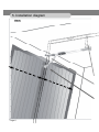
1
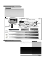
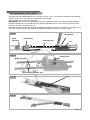
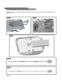
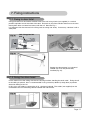
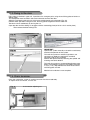
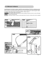
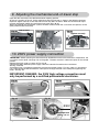
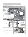
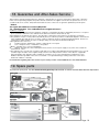
Installation instructions
Rev.06/08 ENG
8500V-Rol/ DUCATI UP 70 (CTH29E)
Garage door automation system 70 kg
Kg
100 kg
max. 8 m2
Power supply
230 V/ 50 Hz W60
Motor
8–24 V dc
Operating temperature
-10 °C / + 50 °C
Opening/closing time
11–18 sec.
2
Ans
*
Min.
5 cm
NTIE
NZIA
* GARA
GAA
RoHS
MADE IN ITALY
Retractable door
max.
h 2,30 m
MAXIMUM HEIGHT OF DOOR
Sectional door
max.
h 2,15 m
IMPORTANT:
The door must slide smoothly and be well balanced.
Read all of these instructions carefully before commencing
installation. For any further information, please contact the
manufacturer: Allducks
Canopy door
max.
h 2,15 m
DHA srl
via Agrate 99/7
20863 Concorezzo (MB) Italy
Tel. +39/039/9633200
Fax +39/039/9633219
[email protected]
www.automaticgateshop.com
Page 1D
Contents
Introduction
1.
2.
3.
4.
5.
Contents of kit . . . . . . . . . . . . . . . . . . . . . . . . . . . . . . .page 3
Technical data . . . . . . . . . . . . . . . . . . . . . . . . . . . . . . .page 3
Types of door . . . . . . . . . . . . . . . . . . . . . . . . . . . . . . . .page 4
Installation criteria . . . . . . . . . . . . . . . . . . . . . . . . . . . .page 5
Installation diagram . . . . . . . . . . . . . . . . . . . . . . . . . .page 6-7
Assembly
6.1
6.2
6.3
6.4
Assembly of the “U” channel rail . . . . . . . . . . . . . . . . . .page 8
Return pulley and preassembled accessories . . . . . . .page 8
Assembly of the chain . . . . . . . . . . . . . . . . . . . . . . . . .page 9
Assembly of the drive plate . . . . . . . . . . . . . . . . . . . .page 10
Fixing
7.1
7.2
7.3
7.4
Fixing to the door lintel. . . . . . . . . . . . . . . . . . . . . . . . page
Fixing the drive head . . . . . . . . . . . . . . . . . . . . . . . . . page
Fixing to the door . . . . . . . . . . . . . . . . . . . . . . . . . . . . page
Chain tensioner . . . . . . . . . . . . . . . . . . . . . . . . . . . . . page
Release
8.
Manual release . . . . . . . . . . . . . . . . . . . . . . . . . . . . . .page 13
End of travel
9.
Adjusting the mechanical end-of-travel stop . . . . . . . .page 14
Power supply
connection
10. 230V power supply connection . . . . . . . . . . . . . . . . . .page 14
11. CTH29E circuit board . . . . . . . . . . . . . . . . . . . . . . . . .page 15
Rolling code remote
control
12.
12.
A) Storing the transmission code . . . . . . . . . . . . . . . .page 16
B) Erasing codes from memory . . . . . . . . . . . . . . . . .page 16
Power adjustment
13.
Power adjustment . . . . . . . . . . . . . . . . . . . . . . . . . . . .page 16
Accessoires
14.
Optional accessories . . . . . . . . . . . . . . . . . . . . . . . . .page 17
Troubleshooting
16. Quick troubleshooting: . . . . . . . . . . . . . . . . . . . . . . . .page 17
CE Conformity
17.
Guarantee and
After-Sales Service
18. Guarantee and After-Sales Service . . . . . . . . . . . . . .page 19
Spare parts
Spare parts . . . . . . . . . . . . . . . . . . . . . . . . . . . . . . . . . . . . .page 19
Page 2
11
11
12
12
Declaration of conformity . . . . . . . . . . . . . . . . . . . . . .page 18
1. Contents of kitUP70
8500V-UP 70 -UP70 kit
Geared motor unit 24V d.c.
CTH29E circuit board
1 x 2-channels rolling code 433 MHz remote control
Chain drive
270 cm “U” channel rail ( 3 x 90 cm) + 2 sleeves
manual release system
Nuts and bolts and preassembled accessories
Installation instructions
Fig. 1
door lintel
fixing plate
releaseRef.
lever812 connecting
Preassembled
rods for standard retractable door
Geared motor unit
(drive head) trolle
motor securing brackets
release
cable with
sleeve
door fixing
plate
no. 1 remote control
Ref. 6203/ rolling
code
chain
chain anchor plate
chain tensioner
sectional door accessory
#992014
Connecting sleeve
Ref. 830
mechanical
travel limiter
in door open
position
Connecting sleeve
Ref. 830
“U” channel guide
Ref.829
“U” channel guide
Ref.829
“U” channel guide
Ref.829
2.Technical data
kit UP 70
Power supply* ( Vac 50/60/Hz)
230V
Lifting force (N)
70
Absorbed power (W)
80
Toroidal transformer
105W
Protection fuse
Radio frequency
Speed (m/sec.)
Operating temperature (°C min/max)
Courtesy light
Amperometric safety system
Power adjustment
End of travel
0.8A T
433 MHz
0.15
-10/+50
Yes
Yes
with trimmer
amperometric detection
+ end of travel open position
Page 3
3. Types of door
3.1 Sectional door
Fig. 2
For installation on a sectional door, it is
necessary to use accessory Ref. 992014,
which is supplied in the kit. Install the
accessory on the door fixing plate to replace
one of the two preassembled Ref. 812
connecting rods for standard retractable doors.
Sectional door accessory: Ref.
992014 is supplied in the kit
IMPORTANT:
La port doit avoir un mouvement glissant, et
être bien équilibrée!
3.2 Retractable door
Fig. 3
For installation on a retractable door, no
additional accessory is required.
IMPORTANT:
The door must slide smoothly and be wellbalanced!
3.3 Canopy door
For installation on a canopy door, it is
necessary to add optional accessory: Ref.
992012*
The canopy door accessory Ref. 992012 must
be purchased separately and is not included in
the kits. Specific installation instructions are
supplied with the accessory.
This item can also be purchased on the
www.allducks.it website, in the accessories
section.
IMPORTANT:
The door must slide smoothly and be wellbalanced!
Page 4
Fig. 4
4. Installation criteria
To fix the automation system’s “U” channel rail it is necessary to have a minimum clearance of 5 cm
between the ceiling and the space through which the door moves.
A minimum distance of 1 cm is necessary between the position of the “U” channel rail and the space
through which the door moves. See fig. 7
Power supply 230V - 50/60 Hz
Fig. 5
“U” channel rail
Distance: min.5 cm
Drive head – geared motor unit complete with
circuit board
Manual release cable connected to the door handle
for external operation.
Set of photoelectric cells (optional accessory not
included in the kit)
Lifting force
= 100 N MAX
MAXIMUM DOOR HEIGHT
Canopy door
Retractable door
Sectional door
max.
h 2,15 m
max.
h 2,30 m
Fig. 7
max.
h 2,15 m
IMPORTANT: for installation
on this type of door, optional
accessory 992012 is
necessary
ceiling
rail
rail=3 cm
Min. 1 cm
Min. 5 cm
Fig. 6
Page 5
5. Installation diagram
Fig. 8
90 cm
Page 6
30 cm
90 cm
Mechanical end-oftravel stop
90 cm
Fixing the motor unit to the ceiling
Fix the motor between the supplied fixing straps.
The motor unit must be fixed to the ceiling so that the “U” channel rail is as horizontal
as possible.
Position the motor centrally with respect to the width of the garage door.
Additional rail support
The rail connecting sleeves Ref. 830 have lateral holes for additional fixings to the ceiling using a cable or a
steel strap (not supplied).
Fixing to the door lintel
The fixing plate must be fixed to the door lintel or the wall.
It is important that the structure in the fixing area be strong and sturdy.
Choose a position on the vertical line corresponding to half the door width. Ensure that you allow sufficient
clearance so that the moving door does not come into contact with the rail. See fig. 7
Fixing to the door
The fixing plate must be fixed to the door.
It is important that the structure in the fixing area be strong and sturdy.
Choose a position on the vertical line corresponding to half the door width.
IMPORTANT:
In the case of a sectional door, it will be necessary to use the 992014 accessory, which must be connected
to the door fixing plate to replace one of the two preassembled Ref. 812 connecting rods for retractable
doors. (see page 4)
In the case of a sectional door, it will be necessary to use accessory 992012 (see page 4), which must be
connected to the door fixing plate. Specific instructions are supplied with accessory 992012.
Page 7
6. Assembly instructions
6.1 Assembly of the “U” channel rail
Connect the 3 pieces of “U” channel rail (Ref. 829) using the connecting sleeves Ref. 830.
See Figs. 9-11
829
Fig. 9
830
829
829
829
830
Fig. 10
830
Fig.11
829
829
830
829
6.2 Return pulley and preassembled accessories
Fig. 12
car
chain return
pulley
wall fixing
plate
Accessory for sectional door:
Ref. 992014 (use only with a
sectional door)
chain tensioner
Page 8
chain anchor plate
6.3 Assembly of the chain
Feed the chain Ref. 818 through the car as shown in Figs. 13-14. Pay particular attention to the direction
shown in Figs. 13-14. Pass the chain around the return pulley.
Connect the chain as shown in the photo.
IMPORTANT: The chain anchor plate (Ref. 819) must connect the chain in a specific position between
the pulley and the car, on the side of the car opposite the release lever. The notch in the anchor plate
must face inwards, as shown in fig. 14
Introduce the chain, the car and the other assembled components into the “U” channel rail. See Figs. 15-16.
The chain anchor plate ref. 819 must be located 13 cm from the centre of the return pulley.
Fig. 13
release lever
Chain
tensioner
return pulley
Chain Ref. 818
Fig. 14
car
release lever
Notch on inside
chain anchor plate Ref. 819
Fig. 15
rail
Fig. 16
Page 9
6.4 Assembly of the drive plate
Insert the rail into the motor unit positioning guides and pass the chain ref. 818 around the sprocket wheel.
See Fig 17-19.
Fig. 17
Chain pulley
Fig. 18
chain
guides
guides
pulley
Fig. 19
Fig. 20
Fig. 21
Page 10
rail
7. Fixing instructions
7.1 Fixing to door lintel
Fixing plate 828 must be fixed to the door lintel or the wall using 2 bolts (not supplied) in a vertical
position equivalent to half the width of the door. Ensure that you allow sufficient clearance so that the
moving door does not come into contact with the rail. See also Fig. 7
It is important that the structure in the fixing area be strong and sturdy. If necessary, reinforce it with a
steel plate.
Fig. 22
Wall fixing plate Ref.
828
Fig. 23
rail
Wall fixing bolt
chain tensioner
Fig. 24
Support the door-opener in a horizontal
attitude until it can be permanently
installed (Fig. 24).
7.2 Fixing the drive head
Fix the motor unit to the ceiling with the two securing brackets, bending the ends at 90°. Fixing the rail
to the ceiling is optional, but it is recommended if using accessory 992012 (canopy door) to prevent
excessive flexing of the rail.
In this case, use cables to support the rail in a horizontal attitude. The cables (not supplied) can be
connected to the rail connecting sleeves between the lateral holes.
Fig. 25
16
Fig. 26
Fig. 27
Page 11
7.3 Fixing to the door
Drill 2 holes in the door’s upper rail, if possible at its strongest point, using the wall fixing plate ref. 828 as a
drilling guide.
This component must be fixed in the exact horizontal centre of the door.
Adjust the connecting rods ref. 812 to the most suitable length using the holes (Fig. 29).
Perform these operations with great care, ensuring perfect alignment with the slide rails.
Tension the chain moderately by turning the nut.
Open the door until the sliding car engages with the connecting plate (ref. 819 = chain anchor plate)
Then remove the door locking bars.
Fig. 29
Fig. 28
IMPORTANT:
Operate the system manually to check the satisfactory
mechanical operation of the system.
Fig. 30
To install the system on sectional type doors, use
connector ref. 992014 to replace the standard
connecting rod ref. 812 supplied.
Perform the replacement by removing the spindle and
inserting connector 992014.
To install the system on counterweighted/canopy type
doors, install optional accessory ref. 992012 ensuring
a 4 cm (1 1/2") drop between the drive head and the
wall fixing plate ref. 828.
Mechanical installation is now complete.
7.4 Chain tensioner
Once the automation system is installed, tension the chain moderately.
To adjust the chain tension, turn the nut.
Fig. 31
Page 12
chain tension adjusting nut
8. Manual release
An emergency manual release system is supplied for manual operation of the door. Comprising a steel
cable and sleeve, it must be connected to the car and to the door handle. Pass the steel cable through
the lug on the car and slide it into the sleeve (Fig. 34). Pass the cable and the sleeve through the holes
in the door fixing plate (Fig. 36) and secure the cable as shown in fig. 37.
To release, turn the door handle anti-clockwise
To lock, move the door manually until the chain anchor plate Ref. 819 locks into the car (this will happen
automatically when moving the door)
WARNING: to operate the door using your radio remote control, the chain anchor plate must be engaged
in the car!
Manual release lever
Fig. 32
Fig. 33
release cable
Fig. 34
sleeve
steel
cable
Fig. 35
Fig. 38
Fig. 36
sleeve
door fixing
plate
Fig.37
steel cable
cable clamp
door
handle
Page 13
9. Adjusting the mechanical end-of-travel stop
Open the door manually to the desired maximum opening position.
At the car’s position on the rail, fix the mechanical end-of-travel stop as shown in the following drawings.
Important: tighten securely so that the end-of-travel stop does not move. When the end-of-travel stop is
correctly positioned, tighten the small central set screw (figs. 40-41).
When you operate your automation system, the door will close when the car touches and presses on the
open position end-of-travel stop.
Fig. 39
end of travel
rail
Fig. 40
Fig. 41
tighten securely
car
end-of-travel stop
end-of-travel stop
10. 230V power supply connection
IMPORTANT: before operating the door electrically ALWAYS ensure that the mechanical components, the
car and the anchor plate (see page 13) are engaged. The door must be in neither the open nor the closed
position.
Remove the plastic cover as shown in Figs. 42-43
Connect the 230 V 50/60 Hz power supply cable to the terminal located on the transformer.
See Fig. 44-45-46
A protection fuse is installed to protect the circuit board and the system. For your safety, it is essential to
use a cable clamp positioned where the cable passes through the hole in the steel plate supporting the
motor. See Fig. 46
IMPORTANT. DANGER: the 230V high voltage connection must
only be performed by a certified professional electrician.
Fig. 42
Fig. 43
cover
Fig. 44
Fig. 45
Fig. 46
transformer
circuit board
motor
230V
Page 14
230V
Protection fuse
5x20mm 1AT fast
230
V
cable clamp
11. CTH29E circuit board
This circuit board is equipped with an amperometric safety system.
If an obstacle is detected, it stops movement.
It automatically stops movement in opening and closing directions (amperometric detection).
Connection for optional accessories: Photoelectric cells (Ref. SW7012); key-operated switch (Ref. SW5000).
Hybrid receiver
Fig. 47
P1
Aerial
-
RV1 = power
adjustment
LED
+
Halogen bulb 20V
24W
Connectio
n to
transforme
r red (24V)
and black
(0) cables
Connection “M”
motor cables
red (left) blue (right)
+
-
ST FTC Com +
0,5 mm2 cable
START
0,5 mm2 cable
Photoelectric
cell
transmitter
(optional)
P1 = storage/erasure of codes for the remote control or the
radio keypad (optional accessory)
LED = Red light. Power supply on and indicator for radio
code storage
RV1 = power adjustment trimmer
M = connection to motor
ST = start n.o.(contact normally open)
FTC = n.c. photoelectric cells (contact normally closed)
Com = common
+ = power 24V
IMPORTANT: if the optional photoelectric cells have
not been connected, the jumper connecting FTC and
COM must be in place. Otherwise, the automation
system will no longer close!
Fig. 48
0,5 mm2 cable
Key-operated
switch
(optional)
0,5 mm2 cable
0,5 mm2 cable
Photoelectric cell
TX (optional)
transformer cables
RED and BLACK
IMPORTANT: do not
remove the jumper
between the FTC
and COM terminals
except in the event of
connection of a pair
of photoelectric cells.
Otherwise, the
automation system
will no longer close.
230V
Alimentation
BLUE
motor
cable
RED
motor
cable
BLUE
motor
cable
RED
motor
cable
Page 15
12. Ref. 6203 Rolling radio remote control
The Ref. 6203 Rolling remote control incorporates 3 radio transmission channels, corresponding to:
1st channel = ON button
2nd channel = OFF button
Each transmission channel, and therefore each button, transmits a unique factory-set code on radio
frequency 433 MHz, using the coding system known as “rolling code”.
Each button can be used to operate a different drive unit in the DUCATI range.
The code, which is secret and cannot be copied, is determined automatically from a choice of more than
a billion possible combinations.
This system ensures that only your remote control will be able to open your automatic door.
A) Store the transmission code in your automation system:
- First check that the 230V power supply is connected and that the protection fuse is in good
condition.- The door must not be moving,
1) Press the P1 key on the automation system circuit board for 1 second.
The red LED illuminates with a steady light.
2) Release the P1 key
3) Within 8 seconds, hold down the key on your remote control (6203 rolling) that you wish to
use to operate the automation system.
The circuit board’s red LED will flash once, then it will remain illuminated and will extinguish
after a few seconds
4) Press again on the remote control to initiate operation
- your remote control has been stored in the automation system circuit board memory.
IMPORTANT: The circuit board memory can store a maximum of 10 different codes.
B) Erase the circuit board memory (total erasure of memory):
If the memory is full or if you lose a remote control, the memory must be erased (all the codes will be
erased) and all the codes must be reinput into the circuit board.
The door must be closed and immobile.
Press button P1 for approximately 20 seconds until the LED flashes 1 sec.
Release P1All the codes have been erased from the automation system memory. Input the new codes following
steps 1-4
Fig. 49
circuit board
CTH29E
P1
1st button = 1st transmission
channel with a unique “rolling”
transmission code
red LED
2nd button = 2nd transmission
channel with the second unique
“rolling” transmission code
13. Power adjustment
To adjust the automation system’s power in accordance with your door’s weight and friction in operation,
use the RV1 trimmer on your automation system circuit board.
First perform an opening and closing operation to check whether the power is
Fig.50
RV1
adequate for satisfactory operation (if the door stops before reaching the end of
travel, the power must be increased)
+
Turn RV1 anti-clockwise to reduce the power.
Turn RV1 clockwise to increase the power.
Page 16
14. Optional accessories
Remote control
6203 rolling*
Switch
SW5000
wide-angle
mirror
SW7950
set of photoelectric cells
SW7012
counterweighted canopy
door accessory
992012
Ref. SW6500
Radio Keypad
go to www.automaticgateshop to purchase optional accessories or spare parts.
15. Maintenance
Courtesy light
Replace your circuit board courtesy light with the following model:
Halogen bulb 20V 24W
Remote control batteries:
Battery life under average use = 2 years (not guaranteed)
Replace the battery with the following model:
12V type A23 - 5mA
Protection fuse:
In the event of a short-circuit or failure of the fuse, replace it with the following model:
5x20 mm 1A T fast fuse ( see Fig. 40, page 14)go to www.automaticgatesho
16. Quick troubleshooting:
1) The automation system does not work at all:
- Check connection of 230 V power supply
- Check the protection fuse and replace if necessary
- Check the operation of the motor with a ‘start’ signal
- Check that the remote control code has been correctly stored in the automation system circuit
board. If necessary, erase the circuit board memory and reinput the codes to the memory.
2) The door opens but will not close:
- Check that the photoelectric cell jumper is present and making a good connection if photoelectric
cells are not installed.
- Check correct alignment of photoelectric cells (if installed) and that they are clean internally and
externally
3) The automation system does not receive a signal from the remote control beyond a certain distance:
- There could be radio interference which can reduce the remote control transmission range.
4) The door does not stop in the desired position:
- Check the power setting (RV1)
- Check that there is no area of excessive friction when opening or closing the door (manual test)
Page 17
ITALY
RoS
18. Guarantee and After-Sales Service
This product is guaranteed against defects in materials or manufacture for a period of 24 months from the date of purchase.
In the event of repair being required, the product must be returned to the supplier from whom it was purchased or to one of
our authorised service centres. Only authorised technical service centres are recognised as qualified to perform repairs
DHAsrl
Via Agrate,99/7 20863 Concorezzo (MB) ITALY
Tel. +39/039/9633200 Fax +39/039/9633219 [email protected]
Conditions of warranty
1.The guarantee is accepted only if the guarantee certificate is completed in full and accompanied by the invoice or receipt as
proof of purchase; furthermore, the certificate itself shall not be altered or defaced in any way.
2.DHA obligations are limited to the repair or, at its discretion, replacement of the product or any defective components.
3.The guarantee in respect of this product automatically becomes void if the product is modified and adapted to technical and
safety standards other than those in force in the country for which the product is designed and manufactured. Therefore no
compensation shall be payable in respect of damage arising out of the above-mentioned modifications.
4.This guarantee does not cover:
a)
Periodic inspection, maintenance, repairs or replacement of worn parts.
b)
Cost of transport, travel, or installation of the product.
c)Misuse, operating errors or incorrect installation.
d)
Damage caused by fire, water, natural phenomena, storms, incorrect power supply or any other cause outside the
manufacturer’s control.
5.This guarantee does not affect the customer’s legal rights in accordance with applicable national legislation in force, nor the
customer’s rights in relation to the supplier arising out of the sales and purchase contract. In the absence of applicable
national legislation, this guarantee shall constitute the customer’s sole recourse and neither the manufacturer nor his
distributor shall be responsible in the event of accidental or consequential damage resulting from breach of the abovementioned conditions of warranty
For information regarding after-sales service in your country, contact: [email protected] or visit www.allducks.it
19. Spare parts
To purchase spare parts, visit the www.automaticgateshop.com website or contact the After-Sales Service department.
Fixing kit
809
831
2 x812
2 x 821
834
828
835
810
832
811
992014
825
Chain kit
839 Chain sprocket
wheel
motor
8000
R403 UE
transformer230V
105W
818
819
CTH 29E
Rail kit
830
8500VT
830
829
829
Drive head complete with
circuit board and transformer
829
Page 19