1
Dell™ PowerEdge Expandable RAID Controller 3/QC, 3/DC, 3/DCL and
3/SC
WebBIOS
Configuration Utility
Guide
www.dell.com | support.dell.com
____________________
Information in this document is subject to change without notice.
©2002DellComputerCorporation.Allrightsreserved.
Reproduction in any manner whatsoever without the written permission of Dell Computer
Corporation is strictly forbidden.
Trademarks used in this text: Dell, the DELL logo, Dell OpenManage and PowerEdge are
trademarks of Dell Computer Corporation. MegaRAID is a registered trademark of LSI Logic
Corporation. Microsoft, Windows, and Windows NT are registered trademarks of Microsoft
Corporation. Intel is a registered trademark of Intel Corporation.
Other trademarks and trade names may be used in this document to refer to either the entities claiming
the marks and names or their products. Dell Computer Corporation disclaims any proprietary interest
in trademarks and trade names other than its own.
Model PERC 3
July 2002
P/N 48TCJ
Rev. A04
Contents
1 WebBIOS Configuration Utility
Features .
. . . . . . . . . . . . . . . . . . . . . . . . . . . . . .
Starting the WebBIOS Utility
Main Menu Screen . . . .
. . . . . . . . . . . . . . . . . . .
3
4
. . . . . . . . . . . . . . . . . . . . . .
5
. . . . . . . . . . . . . . . . . . . . . . . . .
7
. . . . . . . . . . . . . . . . . . . . . . . . . . . .
9
WebBIOS Toolbar Icons
Adapter Properties
Scan Devices
SCSI Channel Properties
Properties .
. . . . . . . . . . . . . . . . . . . . . .
10
10
. . . . . . . . . . . . . . . . . . . . . . . . .
11
. . . . . . . . . . . . . . . . . . . . . . . . . .
11
. . . . . . . . . . . . . . . . . . . . . . . . . . . .
12
. . . . . . . . . . . . . . . . . . . . . . . . . . . .
13
Other Options
Initialize
. . . . . . . . . . . . . . . . . . .
. . . . . . . . . . . . . . . . . . . . . . . . . . .
SCSI Channels
Logical Drives
2
Check Consistency .
Properties .
. . . . . . . . . . . . . . . . . . . . . . .
13
. . . . . . . . . . . . . . . . . . . . . . . . . . .
14
Boot from a Logical Drive
Physical Drives
. . . . . . . . . . . . . . . . . . . .
15
. . . . . . . . . . . . . . . . . . . . . . . . . . .
16
Configuration Wizard
. . . . . . . . . . . . . . . . . . . . . . . .
Select Configuration
Array Definition
17
. . . . . . . . . . . . . . . . . . . . . .
18
. . . . . . . . . . . . . . . . . . . . . . . . .
19
Logical Drive Definition
. . . . . . . . . . . . . . . . . . . . .
20
Configuration Preview .
. . . . . . . . . . . . . . . . . . . . .
23
. . . . . . . . . . . . . . . . . . . . . . . . .
24
Adapter Selection .
Physical View\Logical View .
. . . . . . . . . . . . . . . . . . . .
25
Contents
1
Configuration Mismatch .
. . . . . . . . . . . . . . . . . . . . .
26
. . . . . . . . . . . . . . . . . . . . . .
27
. . . . . . . . . . . . . . . . . . . . . . . . . . . .
27
Random Array Deletion
Overview
Configuration Constraints
. . . . . . . . . . . . . . . . . . .
Procedure for Deleting Logical Drives
Index
2
Contents
28
. . . . . . . . . . . . .
29
. . . . . . . . . . . . . . . . . . . . . . . . . . . . . . . . . . .
31
1
SECTION 1
WebBIOS
Configuration Utility
Features
Starting the WebBIOS Utility
WebBIOS Toolbar Icons
Adapter Properties
Scan Devices
SCSI Channel Properties
Logical Drives
Physical Drives
Configuration Wizard
Adapter Selection
Physical View\Logical View
Configuration Mismatch
Random Array Deletion
w w w . del l .c om | s upp ort .d el l. c om
Features
The WebBIOS Configuration Utility allows you to configure and manage
RAID arrays and logical drives. WebBIOS is an HTML-based utility that is
embedded in the firmware in the PERC 3 controller.
NOTE: The term "PERC
3" in this document refers
to PERC 3/QC, PERC
3/DC, PERC 3/DCL, and
PERC 3/SC.
NOTE: The BIOS
Configuration Utility
(<Ctrl> <M>) is also
used to configure and
maintain RAID arrays,
and logical drives and to
manage the RAID system.
This character-based
utility is independent of
any operating system.
Refer to the PERC 3
User’s Guide for more
information. The
WebBIOS Adapter
Selection screen has a
button you can click to go
to the BIOS Configuration
Utility. One difference
between the programs is
that WebBIOS can
perform reconstructions,
but the BIOS
Configuration Utility
cannot.
2
The WebBIOS Configuration Utility configures disk arrays and logical
drives. Because the utility resides in the BIOS, its operation is independent
of the operating systems on your computer. The WebBIOS utility can be
used to:
•
Display adapter properties
•
Scan devices
•
Display SCSI channel properties
•
Define logical drives
•
Initialize logical drives
•
Check data for consistency
•
Configure physical arrays
•
Reconfigure existing arrays (RAID level migration and capacity
expansion.)
•
Select adapters
•
Display the physical properties of disk drives
You can use the Configuration Wizard to guide you through the steps
required for configuration.
WebBIOS Configuration Utility
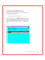
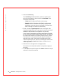
Starting the WebBIOS Utility
When the host computer boots, hold the <Ctrl> key and press the <H>
key when the following text appears:
Copyright© LSI Logic Corporation
Press <Ctrl><M> to Run Configuration Utility
Or press <Ctrl><H> for WebBIOS
After you press <Ctrl><H>, the Adapter Selection screen displays. You
use this screen to select the adapter that you want to configure. Select an
adapter and press Start to begin the configuration. If you want to use the
BIOS Configuration Utility instead of WebBIOS, click the Control-M
button.
Adapter Selection Screen
WebBIOS Configuration Utility
3
w w w . del l .c om | s upp ort .d el l. c om
NOTE: If there is a
configuration mismatch
between the disks and the
NVRAM (Non-volatile
Random Access Memory)
on the adapter, the Select
Configuration screen
appears first. This screen
is used to perform custom
configuration, auto
configuration with
redundancy
(recommended), or auto
configuration without
redundancy. See page 17
for information about
selecting configurations,
and page page 26 for
information about
configuration
mismatches.
4
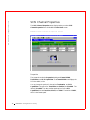
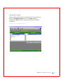
Main Menu Screen
The Main Menu screen displays a menu of items that you can select to
display information and make changes to the RAID arrays attached to
PERC 3 controllers in the server. The screen also displays the current
configuration of the physical and logical drives. From this screen, you can
configure and manage the RAID arrays on the server.
WebBIOS Main Menu Screen
WebBIOS Configuration Utility
WebBIOS Toolbar Icons
Table 1-1 describes the WebBIOS toolbar icons.
Table 1-1. WebBIOS Toolbar Icons
Icon
Description
Click this icon to return to the WebBIOS main menu
screen ("home page").
Go to Home Page
Click this icon to return to the page you accessed
immediately before the current page.
Go to Previous Page
Click this icon to exit the WebBIOS utility.
Exit WebBIOS
Utility
Click this icon to display the adapters that you can
select.
Adapter Selection
Click this icon to scan for adapters connected to your
system.
Scan for Adapters
Click this icon to display the properties of the adapter,
such as the firmware version, BIOS version, RAM size,
and initiator ID.
Adapter Properties
Click this icon to enter the Configuration Wizard.
Configure Adapter
WebBIOS Configuration Utility
5
w w w . del l .c om | s upp ort .d el l. c om
T a b l e 1 - 1 . W e b B I O S T o o l b a r I c o n s (continued)
Icon
Description
Click this icon to turn off the sound on the alarm.
Silence the Alarm
Click this icon to go from the WebBIOS Configuration
Utility to the BIOS Configuration Utility that resides in
the firmware.
Go to BIOS
Configuration
Utility
The BIOS Configuration Utility (<Ctrl><M>) is used
to configure and maintain RAID arrays and logical drives
and to manage the RAID system. This character-based,
non-GUI utility is independent of any operating system.
NOTE: Refer to the PERC 3 User’s Guide for
more information about the BIOS Configuration
Utility.
6
WebBIOS Configuration Utility
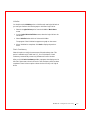
Adapter Properties
The Adapter Properties screen appears when you select Adapter Properties
from the WebBIOS Main Menu screen.
WebBIOS Adapter Properties Screen
Table 1-2 describes the Adapter Properties menu options.
Table 1-2. Adapter Properties Menu Options
Option
Description
Firmware Version
Firmware version number
BIOS Version
BIOS version number
RAM Size
Size of the random access memory
NOTE: The Battery
Backup and Cluster Mode
fields are displayed only
for controllers that
support these features.
WebBIOS Configuration Utility
7
w w w . del l .c om | s upp ort .d el l. c om
T a b l e 1 - 2 . A d a p t e r P r o p e r t i e s M e n u O p t i o n s (continued)
Option
Description
Initiator ID
Identifying number for the card. You can change the
Initiator ID only when you are in cluster mode. You cannot
change the ID while in standard mode. The ID can be a
number from 0 to 15. We recommend that you use 6 or 7.
When you are in standard mode, the ID is always 7.
Rebuild Rate
Selects the rebuild rate for drives attached to the selected
adapter. The rebuild rate is the percentage of system
resources dedicated to rebuilding a failed drive. A rebuild rate
of 100 percent means the system is totally dedicated to
rebuilding the failed drive. The default is 30 percent.
Spinup
Parameters
Sets the timing for spinning up the hard disk drives in the
computer. The options are Automatic, 2 per sec, 4 per sec, or
6 per sec.
FlexRAID
PowerFail
Enables or disables the FlexRAID PowerFail feature. This
option allows drive reconstruction, rebuild, and check
consistency to continue when the system restarts because of
a power failure, reset, or hard boot.
Alarm Control
Enables, disables, or silences the onboard alarm tone
generator. The alarm sounds when there is a change in a drive
state, such as when a drive fails or when a rebuild is
complete.
Adapter BIOS
Enables or disables the BIOS on the adapter. If the boot
device is on the RAID controller, the BIOS must be enabled;
otherwise, the BIOS should be disabled, or it might not be
possible to use a boot device elsewhere.
Cluster Mode
Enables or disables cluster mode. Cluster mode allows the
controller to operate as part of a cluster. When you disable
cluster mode, the system operates in standard mode. In
addition, when you enable cluster mode, the system
automatically disables the BIOS.
NOTE: The Cluster Mode field appears only for
controllers that support clustering.
Battery Backup
Indicates whether the battery backup is present or absent.
NOTE: The Battery Backup field appears only for
controllers that support this feature.
8
WebBIOS Configuration Utility
T a b l e 1 - 2 . A d a p t e r P r o p e r t i e s M e n u O p t i o n s (continued)
Option
Description
Fast
Initialization
When enabled, zeros are written to the first sector of the
logical drive so that initialization occurs in 2 – 3 seconds.
When disabled, a full initialization takes place on the entire
logical drive. On a larger array (over 5 arrays), it is best to set
fast initialization to Disabled, then initialize. Otherwise, the
controller will run a background consistency check within
five minutes of reboot or RAID 5 creation.
Cache Flush
Timings
Selects the amount of time between cache flushes. The
contents of the cache are flushed to maintain data integrity.
Auto Rebuild
When enabled, drives are automatically rebuilt when they
fail.
Set Factory
Defaults
Select Yes to load the default WebBIOS Configuration
Utility settings. "Logical Drive Definition" on page 20 lists
some of the default settings.
Scan Devices
When you select Scan Devices from the Main Menu screen, WebBIOS
checks the physical and logical drives to see if there are any changes to the
drive status. It displays the results of the scan on the Main Menu screen in
the physical and logical drives section. For example, if a physical drive has
failed, the word Failed displays to the right of the drive name under the
Physical Drives heading.
WebBIOS Configuration Utility
9
w w w . del l .c om | s upp ort .d el l. c om
SCSI Channel Properties
The SCSI Channel Properties screen displays when you select SCSI
Channel Properties from the WebBIOS Main Menu screen:
WebBIOS SCSI Channel Properties Screen
Properties
The properties under the Properties heading are Channel Width,
Termination, and SCSI Capabilities. The Channel Width row displays the
SCSI bus width, in bits.
You can change the options for the options Termination, and SCSI
Capabilities. The options for Termination are Enabled, and Disabled. The
default is Enabled. The data transfer speed options for the SCSI
Capabilities field are Fast, Ultra, Ultra-2, and 160M. The default is 160M,
which is the fastest speed.
10
WebBIOS Configuration Utility
SCSI Channels
The SCSI Channels section of the screen lists the channels on the selected
controller, and the values for the properties.
Click Submit to save changes to the options. Click Reset to undo any
changes and return to the configuration that existed before you made any
changes.
Other Options
The other options on this screen are:
•
Home: Click Home to return to the main menu screen.
•
Back: Click Back to return to the previous screen.
WebBIOS Configuration Utility
11
w w w . del l .c om | s upp ort .d el l. c om
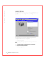
Logical Drives
The Logical Drives screen displays when you select Logical Drives from the
Main Menu screen or click a logical drive in the list of logical drives on the
Main Menu screen.
WebBIOS Logical Drives Screen
The upper right section of the screen displays the logical drives that
currently exist. Below that section are options to:
•
Initialize a logical drive
CAUTION: Initializing a logical drive destroys all data on the
logical drive.
12
•
Check the consistency of redundancy data on a logical drive
•
Display the logical drive properties
•
Boot from a logical drive
WebBIOS Configuration Utility
Initialize
You should use the Initialize option to initialize each new logical drive that
you configure. Perform the following steps to initialize a logical drive:
1
Select the Logical Drives option from the WebBIOS Main Menu
screen.
2
On the Logical Drive Definition screen, select the logical drive to be
initialized.
3
Select Initialize below the list of drives and click Go.
The progress of the initialization appears as a graph on the screen.
4
When initialization completes, click Back to display the previous
menu.
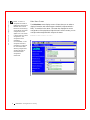
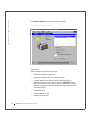
Check Consistency
Select this option to verify the correctness of the redundancy data. This
option is available only if RAID level 1, 5, 10 or 50 is selected. Check
consistency automatically corrects any differences found in the data.
After you click Check Consistency and Go, a progress chart displays on the
left side of the screen to show how much of the consistency check has been
completed. There is also an option to abort the check for any or all logical
drives.
WebBIOS Configuration Utility
13
w w w . del l .c om | s upp ort .d el l. c om
The Check Consistency screen shows a check in progress.
Check Consistency Screen
Properties
Select this option to perform the following:
14
•
Display the logical drive properties.
•
Display or change the read, write, and I/O policies.
•
Enable or disable virtual sizing. (Virtual sizing allows PERC to
determine the drive capacity. Set this option to Enabled before you
add a physical drive to a logical drive. After you have created a logical
drive set, the partition of the drive should be as large as the virtual size
of the logical drive.)
•
Start initialization
•
Start a consistency check
•
Remove a physical drive
WebBIOS Configuration Utility
•
Allow RAID migration. RAID migration means changing the RAID
level of the array. You can optionally add one or more drives to the
array when you change the RAID level.
The following is an example of the Properties screen.
WebBIOS Properties Screen
Boot from a Logical Drive
After you select a logical drive to boot from, the system boots from that
logical drive when you reboot. This field is 0-n, where n = the number of
logical drives created on the controller – 1. For example, it is 0-0 when there
is one logical drive on the controller. Press Go to perform the selected
action or Reset to delete any changes.
WebBIOS Configuration Utility
15
w w w . del l .c om | s upp ort .d el l. c om
Physical Drives
The Physical Drives screen displays when you select Physical Drives from
the Main Menu screen or click a physical drive in the list of physical drives
on the Main Menu screen.
WebBIOS Physical Drives Screen
NOTE: Only two channels
display for PERC 3/DC,
and PERC 3/DCL
controllers, and one for
PERC 3/SC controllers.
16
This screen displays the physical drives for each channel. From this screen,
you can rebuild the physical arrays or view the properties for the physical
drive you select. Select Rebuild or Properties and click Go to perform these
actions. Press Reset to return to the configuration that existed before you
made any changes.
WebBIOS Configuration Utility
Configuration Wizard
The Configuration Wizard screen displays when you select Configuration
Wizard on the WebBIOS Main Menu screen.
Configuration Wizard Screen
On this screen, you can begin the procedure to clear a configuration, create
a new configuration, or add a configuration. After you select one of the
options, click Next to go to step 2/5.
WebBIOS Configuration Utility
17
w w w . del l .c om | s upp ort .d el l. c om
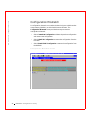
Select Configuration
Step 2/5 displays on the Select Configuration screen. On this screen, you
can select custom configuration, auto configuration with redundancy, or
auto configuration without redundancy.
Select Configuration Screen
Click Next to go to Step 3/5 after you select the type of configuration.
18
WebBIOS Configuration Utility
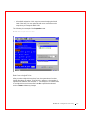
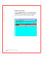
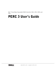
Array Definition
The Array Definition screen displays next. To add drives to an array, press
and hold the Ctrl key while you select "ready" drives on the left side of the
screen. Click Accept Array to add the drives. To undo the changes, press
Reclaim. Click Next to go to Step 4/5. The Array Definition screen shows
an example of an array being added.
Array Definition Screen
In the Arrays window, on the right side of the screen, the Array heading
displays the amount of space available on the hard drives, depending on the
RAID level selected. For example, Array 0 has a capacity of 17136 MB as
RAID 0 (striping), and 8568 MB as RAID 1 (mirroring.) RAID 0 offers the
combined capacity of both drives. RAID 1 offers half the capacity of the two
drives (or the capacity of the smaller of two drives, if they are not the same
size.)
WebBIOS Configuration Utility
19
w w w . del l .c om | s upp ort .d el l. c om
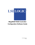
Logical Drive Definition
The Logical Drive Definition screen displays for Step 4/5. Click a logical
drive to display the following screen for that drive. Use this screen to
configure the logical drive:
Logical Drive Definition Screen
Perform the following steps to configure logical drive policies.
NOTE: Only applicable
RAID levels can be
chosen. For example, if
there are two drives, you
cannot select RAID 5,
which requires a
minimum of three drives.
20
1
Click the down arrow the box to the right of the RAID Level field to
display the possible RAID levels for the logical drive.
2
Select a RAID level.
3
Select the Stripe Size.
The Stripe Size specifies the size of the segment written to each disk
in a RAID 1, 5, 10, or 50 logical drive. You can set the stripe size to 2
KB, 4 KB, 8 KB, 16 KB, 32 KB, 64 KB, or 128 KB. The default is 64
KB.
WebBIOS Configuration Utility
A larger stripe size produces higher read performance, especially if your
computer does mostly sequential reads. However, if your computer
does random read requests more often, choose a smaller stripe size.
Select the stripe size based on your performance testing.
4
Select the Read Policy.
The Read Policy controls the SCSI read-ahead feature for the logical
drive. During a read operation, the read-ahead policy determines
whether the controller reads additional data records into cache. The
read-ahead feature allows your system to predict the next data that will
be read. If an application program reads data sequentially (as the disk
stores data), then read-ahead will improve performance, as this
reduces the time needed to access the data. Select the read policy
based on your performance testing. The options are as follows:
5
–
Normal: The controller does not read additional records into
cache.
–
Read-ahead: The controller reads additional records into cache.
–
Adaptive (default): The controller begins using read-ahead if the
two most recent disk accesses occurred in sequential sectors. If all
read requests are random, the read policy reverts to Normal;
however, all requests are still evaluated for possible sequential
operation. Adaptive read-ahead is a good choice because it speeds
sequential read operations.
Select the Write Policy.
The Write Policy specifies whether I/O completion is signaled when
data is transferred to the cache or when it is written to disk. The
options are as follows:
–
Write-back: The controller sends a data transfer completion signal
to the host when the controller cache has received all the data in a
transaction.
–
Write-through (default): The controller sends a data transfer
completion signal to the host when all data in a transaction is
written to disk.
Write-through caching provides better data security than write-back
caching, and write-back caching offers higher throughput than writethrough caching. Write-back is safe to use only if the RAID controller
has battery-backed cache. Select the write policy based on your
performance testing.
WebBIOS Configuration Utility
21
w w w . del l .c om | s upp ort .d el l. c om
6
Select the Cache Policy.
The Cache Policy determines whether reads for a specific logical
driver use cache memory. It does not affect the Read-ahead cache.
The options are as follows:
7
–
Cached I/O: All reads are buffered in cache memory.
–
Direct I/O (default): Reads are not buffered in cache memory.
Direct I/O does not override the cache policy settings. Data is
transferred to cache and the host concurrently. If the same data
block is read again, it comes from cache memory.
Enable or disable the spanning mode for the current logical drive.
If enabled, the logical drive can occupy space in more than one array. If
disabled, the logical drive can occupy space in only one array.
For two arrays to be spannable, they must have the same stripe width
(they must contain the same number of physical drives) and they must
be consecutively numbered. For example, assuming Array 2 contains
four disk drives, it can be spanned only with Array 1 and/or Array 3,
and only if Arrays 1 and 3 also contain four disk drives. If the two
criteria for spanning are met, spanning is automatically allowed. If the
criteria are not met, the Span setting makes no difference for the
current logical drive.
8
Select the size of the logical drive in megabytes (MB.)
The maximum size allowed for the RAID configurations displays on
the screen.
9
22
Click Accept to accept the changes or click Reset to delete the changes
and return to the previous settings.
WebBIOS Configuration Utility
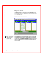
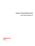
Configuration Preview
Step 5/5 displays a preview of the configuration that you have create in the
shown in Configuration Preview screen. Click Accept to save the
configuration or Back to return to the previous screens and change the
configuration.
Configuration Preview Screen
WebBIOS Configuration Utility
23
w w w . del l .c om | s upp ort .d el l. c om
Adapter Selection
When you select Adapter Selection on the WebBIOS Main Menu screen,
the Adapter Selection screen displays a list of the Dell PERC 3 adapters in
the system. (This screen also appears when you first start the WebBIOS
utility.) To begin configuration, select an adapter and click Start.
WebBIOS Adapter Selection Screen
24
WebBIOS Configuration Utility
Physical View\Logical View
The Physical View and Logical View display on the WebBIOS Main Menu
screen. The option toggles between the Physical View and the Logical View
of the logical drive. For example, if you select Physical View on the screen
below, the option changes to Logical View. If you then click Logical View,
the option changes back to Physical View. This allows you to go back and
forth between physical and logical views.
WebBIOS Physical View/Logical View
WebBIOS Configuration Utility
25
w w w . del l .c om | s upp ort .d el l. c om
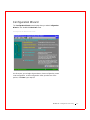
Configuration Mismatch
A configuration mismatch occurs when the data in the non-volatile random
access memory (NVRAM), and the hard drives are different. The
Configuration Mismatch screen provides three ways to resolve a
configuration mismatch:
•
Select Create New Configuration to delete the previous configuration
and create a new configuration.
•
Select View Disk Configuration to restore the configuration from the
hard disk.
•
Select View NVRAM Configuration to restore the configuration from
the NVRAM.
Configuration Mismatch Screen
26
WebBIOS Configuration Utility
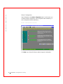
Random Array Deletion
The PERC controllers support random array deletion. Random array
deletion is the ability to delete any unwanted logical drives and use that
space for a new logical drive.
Overview
The main benefit is that you are no longer restricted to sequential or
contiguous logical drives when you create logical drives. You can use
WebBIOS to create the next logical drive from the non-contiguous free
space (‘holes’), and from the newly created arrays. WebBIOS provides a list
of configurable arrays in which there is a space to configure.
The random deletion of logical drives creates non-contiguous segments in
the configuration, which prevents the sequential creation of the next logical
drive. You can create logical drives from these non-contiguous segments. To
create such a logical drive, you can span these segments, as long as they have
the same number of physical drives.
You can still create sequential logical drives, without using the noncontiguous segments. WebBIOS provides information about sequential
segments, non-contiguous segments and physical drives that have not been
configured. You can use this information when you create logical drives.
CAUTION: The deletion of the logical drive can fail under certain
conditions. You cannot delete a logical drive during a
reconstruction.
Deletion can fail during a rebuild, initialization or check
consistency of a logical drive, if that drive has a higher logical
drive number than the drive you want to delete.
NOTE: Drive size
expansion is not possible,
even though you can use
non-contiguous free space
to create a new logical
drive. In addition, you
cannot move an existing
logical drive to another
area to protect it from
defragmentation caused
by random deletion.
WebBIOS Configuration Utility
27
w w w . del l .c om | s upp ort .d el l. c om
NOTE: When a ‘delete’
request reaches the
operating system driver,
the driver stops all the
running input/output (I/O)
for other logical drives
and processes the delete
request first. Normal
read/write operation
resumes after the delete
request is completed.
NOTE: The available
space is shown on the
Array Definition screen,
on page 19. In the Arrays
window, on the right side
of the screen, the Array
heading displays the
amount of space available
on the hard drives,
depending on the RAID
level selected.
Configuration Constraints
The configuration procedure is affected by the random array deletion
feature. The following is a list of constraints to consider when you configure
arrays and logical drives.
•
If you create more than one array, you can choose to create logical
drives from any array by selecting the particular array.
•
The array need not be completely consumed to jump to another array.
You can leave space in an array and proceed to configure in another
array.
•
The available space appears beside each array for possible RAID levels.
•
When you delete a logical drive from an array, in the configuration
screen, the available space shown is the size of the first hole (noncontiguous segment) in the array.
•
Since configuration is allowed in any array in any sequence, the RAID
level option shown in the Logical Drive Definition screen on page 20
is not automatic. You have to choose the RAID level for each logical
drive.
•
For the same reason as above, spanning is not automatic. You must
choose the arrays across which to span the logical drive. Spanning can
be across any array; they do not need to be contiguous.
•
If any two arrays have an equal number of stripes and have holes, those
holes can be spanned by selecting those arrays.
•
To delete a logical drive, click the logical drive. The Logical Drive
Properties page displays. You can choose Delete, then press Go.
WebBIOS deletes the logical drive and displays the space of the first
hole beside the array number in the configuration screen.
Delete is not allowed when any of the following operations is in
progress:
28
–
Reconstruction
–
Rebuild
–
Check consistency
–
Background initialization
WebBIOS Configuration Utility
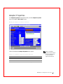
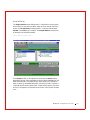
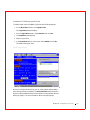
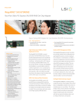
Procedure for Deleting Logical Drives
To delete logical drives in WebBIOS, perform the the following steps:
1
On the Main Menu screen, click Logical Drives.
The Logical Drive screen displays.
2
On the Logical Drive screen, click Properties, then click Go.
3
The Properties screen displays.
4
Select a logical drive.
5
In the Operations section of the screen, select Delete and click Go.
This deletes the logical drive.
Properties Screen
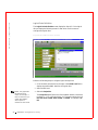
When you configure another array, you can use the space made available
from the logical drive you deleted. The Array Definition screen shows the
amount of space available. See the section about the Configuration Wizard,
starting on page 17, for more information about configuring arrays.
WebBIOS Configuration Utility
29
30
WebBIOS Configuration Utility
w w w . del l .c om | s upp ort .d el l. c om
Index
A
F
P
Adapter Properties, 7
FlexRAID PowerFail, 8
PERC, 14, 29
Adapter Selection, 24
Formatting, 27
Physical Drives, 16
Physical ViewView, 25-2 6
Adaptive, 21
Alarm Control, 8
Array Definition, 19
Auto Rebuild, 9
I
Icons, 5
Initialization
Logical Drives, 29
BIOS, 2 9
L
BIOS Configuration
Utility, 29
Logical Drive Definition, 20
Cache Policy, 22
Cached I/O, 22
R
RAID, 2, 6
B
C
Policy
Cache, 22
Logical Drives, 12
Check Consistency, 13
Initializing, 13
Properties, 14
Read-ahead, 21
Rebuild Rate, 8
S
Scan Devices, 9
SCSI Channel Properties, 10
Select Configuration, 18
CanSpan, 22
M
Clear Configuration, 7
Main Screen, 4
Spanning mode, 22
Configuration Wizard, 17
Memory Type, 8
Starting, 3
Consistency Check, 13
Spanning, 22
Stripe size, 20
N
D
Direct I/O, 22
NoSpan, 22
V
Virtual Sizing, 14
Index
31
32
Index
W
Web BIOS Configuration
Utility, 1
WebBIOS Icons, 5
Write Policy, 21
Write-back, 21
Write-through, 21
32
Index
Printed in the U.S.A.
P/N 48TCJ Rev. A04
www.dell.com | support.dell.com