1
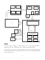
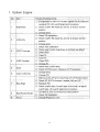
DLP PROJECTOR
PB8250
SERVICE MANUAL
CONTENT
Chapter 1: Engineering Specifications.................................................................................................1
Appendix A Optical Measurement Procedure..............................................................................6
Chapter 2: Spare Parts List.................................................................................................................15
Chapter 3: Product description and operation....................................................................................17
Shipping Contents......................................................................................................................17
Projector Description .................................................................................................................18
Remote Control Description ......................................................................................................21
Installation..................................................................................................................................24
Operation....................................................................................................................................30
Packing Description ...................................................................................................................47
Appearance Description.............................................................................................................52
Lamp Replacement ....................................................................................................................55
Shutdown ...................................................................................................................................60
Shutdown ...................................................................................................................................60
Chapter 4: Circuit Operation Theory .................................................................................................61
Chapter 4: Circuit Operation Theory .................................................................................................61
Chapter 5: Alignment Procedure........................................................................................................69
Chapter 6: Trouble Shooting ..............................................................................................................73
Chapter 7: Schematics drawing..........................................................................................................83
Chapter 1: Engineering Specifications
1
2
3
4
5
Appendix A Optical Measurement Procedure
1. Scope:
This document describes critical optical related test definitions and Instructions for data or
video projectors. The other general terminologies are specified in ANSI IT7.228-1997.
2. General Requirements
1. The unit under test should be allowed to stabilize without further adjustment for a
minimum of 5 minutes, at nominal ambient room temperature of 25°C, before making
measurements.
2. Measurements shall take place in a light proof room, where the only source of
illumination is the projector. Less than 1 lux of the light on the screen shall be from any
source other than the projector.
3. All measurements shall be made on flat screens that do not provide any advantage to the
performance of the unit.
4. All measurements shall be made at standard color temperature setting, 100% white image
(per ANSI IT7.228-1997), except where noted.
3. Practical Requirements
1. When measuring contrast manually, operators should not wear white clothing since light
reflected from white clothing can influence the measurement.
2. Unless otherwise specified, the projection lens is set in the widest zoom position since
zoom function can influence the measurement.
3. Measurement should be performed with Minolta Chromameter, Model CL-100, or
equivalent.
A1. ANSI BRIGHTNESS
ANSI Lumens = (L1+L2+L3+L4+L5+L6+L7+L8+L9)/9 (lux) x A(m^2)
A (Area) = W * H (m^2)
W: width of projected image (m)
H: height of projected image (m)
6
Note: L10, L11, L12, L13 are located at 10% of the distance from corner itself to L5
A2. ANSI UNIFORMITY
ANSI +Uniformity= Maximum (L1~13)-Average (L1~9)/ Average (L1~9)%
ANSI -Uniformity= Minimum (L1~13)-Average (L1~9)/ Average (L1~9)%
A3. JBMA UNIFORMITY
JBMA Uniformity = Average (L1,L3,L7,L9)/ L5
A4. ANSI CONTRAST
ANSI Contrast = Average lux value of the white rectangles/Average lux value of the black rectangles
Contrast Ratio shall be determined from illuminance values obtained from a
black-and-white ”chessboard” pattern consisting of 16 equal rectangles. The white rectangles shall be
at 100% gray and the black rectangles at 0% gray. Illuminance measurements shall be made at the
center of each of the rectangles.
A5. FOFO CONTRAST
FOFO Contrast = Lux value at the center of a solid white screen/the lux value at the center of a solid
black screen
A6. JBMA CONTRAST
7
JBMA Contrast = Average (L1,L2,L3,L4,L5,L6,L7,L8,L9) under solid white / Average
(L1,L2,L3,L4,L5,L6,L7,L8,L9) under solid black
A7. LIGHT LEAKAGE
Leakage = The maximum light leakage under a solid black pattern in or outside of the projected
image
A8. IMAGE DISTORTION
Keystone = (W2-W1)/ (W1+W2) x 100%
Vertical TV dist = (H1+H2-2xH3)/2H2 x100%
Horizontal TV dist = (W1+W2-2xW3)/2W1 x100%
W1: image width at image bottom
W2: image width at image top
W3: image width at the half image height.
H1: image height at image left
H2: image height at image right
H3: image height at half image
Note:
1. Keystone and Vertical TV Distortion are recommended for Front Projection Display
2. Vertical and Horizontal TV Distortion are recommended for Rear Projection Display
A9. THROW RATIO
Throw ratio = projection distance / the width of the projected image
A10. ZOOM RATIO
Zoom ratio = maximum / minimum image diagonal size at a fixed projection distance
A11. FOCUS RANGE
The minimum/maximum focus distance is the minimum/maximum projection distance (The
distance between the outermost element of projection lens and screen), expressed in meter, at which
the image is still at its acceptable focus level.(acceptable focus level is specified by FOCUS LIMIT
SAMPLE approved by customer)
A12. COLOR
Color is expressed as (x, y) in 1931CIE chromaticity values Note: Color is measured at the center of
the screen that is entirely the measured color under default brightness and contrast settings.
A13. ANSI COLOR
ANSI Color is expressed as (u, v) in 1976 CIE chromaticity values Note: Color is measured at the
8
center of the screen that is entirely the measured color under default brightness and contrast
settings.
A14. COLOR UNIFORMITY
Color Uniformity is the maximum color difference (△x, △y) between any two points out of
L1~L13
A15. ANSI COLOR UNIFORMITY
ANSI Color Uniformity: △u’v’= [(u’1-u’0)^2+(v’1-v’0)^2]^1/2
(u’0,v’0): the average color of L1~L13
(u’1,v’1): the spot with maximum deviation from (u’0,v’0)
A16. PROJECTION OFFSET
Projection Offset= Image height above projection lens optical axis / Total image height x 100%
Note: Optical engine should be kept horizontal attitude
A17. BLUE EDGE INSPECTION CRITERIA
The blue edge must invisible with blue pattern 171 (R=50/255, G=100/255, B=255/255)
A18. DEFOCUS AND FLARE TEST PROCEDURE
Procedure:
Step 1: Get best focus at Screen Center with Pattern 1
Step 2: Check specified screen sizes and zoom positions
Step 3: Use Chart1 to measure Defocus and Flare for whole screen of R,G,B color at Pattern 2,3,4
and record the maximum number
Example of 1.5 pixel flare:
A19. LATERAL COLOR TEST PROCEDURE
Procedure:
Step 1: Get best focus at Screen Center with Pattern 1
9
Step 2: Check specified screen sizes and zoom positions
Step 3: Use Chart1 to measure Lateral Color for whole screen with Pattern 5 and record the
maximum number
Example if 0.6 pixel lateral color:
A20. LAMP LIFETIME TEST PROCEDURE
50% lamp brightness maintenance under 3.5hr ON, 0.5hr OFF cycling test
A21. LIGHT LEAKAGE SPECIFICATION
Test under tele 47” to 60”
10
11
12
13
14
Chapter 2: Spare Parts List
PB8250 Spare Parts List
Item No.
Sales Location
Notes
99.J8177.B81
PB8250
99.J8177.B8K
Korea
PB8250
99.J8177.B8T
Taiwan
PB8250
NO. PART NO.
DESCRIPTION
Location
1
22.91008.001
SKT PLUG 2/3P W/G PSE
2
23.10035.011
FAN 12V 60*60*25 GB1206PTV2-A
3
23.10035.051
FAN 12V 60*60*25 GB1206PTV3-A
4
23.10090.021
FAN 12V50*50*20 80M GB1205PKV
5
23.10107.021
FAN DC12V 60*15 70MM AD0612XB
6
23.10110.011
FAN 12V 80*80*25/92*25 SUNON
7
27.01018.000
CORD H05VV-F13A250V 1830MM UK
UK
8
27.01818.000
CORD SVT#18*3C10A125V 1830US
US
9
27.82718.281
CORD H05VV-F 10A250V EUR BLK
EU
10
31.J9401.011
NAME PLATE AL PB8250
11
42.J9406.001
REAR/C PC Y5003A PB8240
12
44.J7601.003
CTN AB PB7100/BENQ(VI)
13
47.J8104.001
BAG CARRY PB8250/8240/8140
14
50.72920.011
C.A MIN-DIN 4P S-VIDEO W/S 15
15
50.73213.501
CABLE 4P USB A-B 1800MM BLACK
16
50.J0508.503
SIGNAL/C 15/15P 20276 1800MM
17
50.J2103.501
CABLE RGA/DVI-A (WHDDC) 1.8M
18
50.J2401.001
CABLE D-SUB/RCA 1800MM/SL705X
19
50.L4302.501
CABLE AUDIO 284C/577C+CORE BL
20
54.J9412.001
BALLAST 300W O4 PB8250 OSRAM
21
55.J1313.001
PCBA 1L SENSOR-B BD SL700 X M
22
55.J5019.001
PCBA THERMAL BD DX850
23
55.J9401.001
PCBA MAIN BD PB8260
24
55.J9405.001
PCBA DC-DC BD PB8260
25
55.J9410.001
PCBA CONNECTOR BD PB8260
26
55.J9412.001
PCBA KEYPAD BD PB8240
27
55.J9423.001
PCBA CHIP BD PB8240
28
55.J9428.001
PCBA REAR IR BD PB8260
15
29
56.26J95.001
REMOTE PB8250 FORWARD
30
60.J8115.001
ASSY POWER+BRIDGE BD PB8250
31
60.J9418.001
ASSY SUB U/C PB8240
32
60.J9420.001
ASSY SUB L/C PB8240
33
60.J9420.002
ASSY SUB LOWER CASE PB8240
34
65.J7603.111
CW DIA46 DEG110 PB2240 PRODIS
35
65.J9301.001
PL ZOOM PB8240 COSINA
36
71.07XGA.B01
IC DMD 0.7XGA DDR 12 FTP PIXE
37
59.J8101.CG1
Service lamp
38
60.J9428.001
ASSY CD+MANUAL PB8250
16
Chapter 3: Product description and operation
Shipping Contents
The projector is shipped with the cables required for connection to a PC and to video equipment.
Carefully unpack and verify that you have all of the items shown below. If any of these items are
missing, please contact your place of purchase.
17
Optional Accessories
1.
2.
3.
4.
5.
6.
Macintosh adapter
250W / 300W lamp module
Ceiling mount kit
Wireless Pro
Presentation Pro
DVI-I cable
Projector Description
18
19
Controls and Functions
20
Remote Control Description
21
Remote Control Effective Range
Infra Red (IR) remote control sensors are located on the front and the back of the projector. The
remote control must be held at an angle within 30 degrees of the projector’s IR remote control
sensors to function correctly. The distance between the remote control and the sensors should not
exceed 6 meters (19.5 feet).
22
Installing or Replacing the Batteries
23
Installation
Choosing a Location
Your projector is designed to be installed in the four installation configurations shown here: Floor
front, Ceiling front, Floor rear, Ceiling rear. Your room layout or personal preference will dictate
which installation configuration you use.
If you place the projector above or below the screen, you have to tile it down or up to center the
image on the screen, in these situations image distortion will occur. Use the Keystone function to
correct the distortion. See keystone correction.
Making Connections
When connecting a signal source to the projector, be sure to:
1. Turn all equipment off before making any connections.
2. Use the correct signal cables for each source.
3. Ensure the cables are firmly inserted.
24
Connecting to a Laptop or Desktop Computer
Connecting Equipment to the Component Video Input
The projector is capable of displaying various High Definition TV display modes. Some of these
sources are:
Most of these sources will provide an analog component video output, a standard VGA output, or a
YPbPr (default) format.
The projector is capable of accepting HDTV data through a Component Video connector. Use a
Component Video cable that came with your projector to display these images.
25
The following standards are supported in the HDTV function:
Connecting to Video or S-Video Devices
Connecting to Display Devices
If you want to monitor your presentation close-up on a monitor as well as on the screen, you can
connect the RGB signal output port on the projector to an external monitor with a VGA cable or
D-Sub - DVI cable.
26
Adjusting the Height
The projector is equipped with 2 quick-release adjuster feet.
Screen Size
Place the projector at the required distance from the screen according to the required picture size
(see the table on the next page).
27
28
29
Operation
Start Up
1. Switch all of the connected equipment on.
2. Plug the power cord into the projector and into a wall socket.
3. Turn on the wall socket switch (where fitted).
4. Turn the main power switch on. The Power indicator lights orange.
5. Press and hold Power on the remote control or projector to start the unit. The Power indicator
light flashes green when the power is turned on.
30
6. The start up procedure takes about 30 seconds after pressing Power. In the later stage of start up,
a default BenQ logo appears.
7. Next, the projector starts to search input signals. Irrespective of selected input source, the screen
shows “Acquiring Signal” at the bottom right corner of the screen. If there is no input source
detected, one of six messages will be displayed on the screen continuously: “Analog RGB
Searching”, “DVI-A Searching”, “DVI-D Searching”, “Analog YPbPr Searching”, “S-Video
Searching”, and “Composite Video Searching”.
8. You can also press Source on the projector or remote control to select your desired input signal.
Digital Keystone Correction
Keystoning refers to the situation where the projected image is noticeably wider at either the top or
bottom. It occurs when the projector is not perpendicular to the screen.
31
Source Selection
Auto Adjustment
32
Blank
Zoom / Focusing
Adjust the projected image to your desired size using the lens’
zoom ring. Then focus the image by rotating the focus ring.
33
Laser Pointer Operation
The Laser Pointer is a presentation aid for professionals. It emits red
colored light when you press it and the LED indicator lights up green.
Do not look into the laser light window or shine the laser light beam on
yourself or others. Refer to the warning messages on the back of the
remote control and the attached “User Information” prior to using it.
Mouse Function Operation
Connect the projector to your PC or notebook with a USB
cable prior to using these functions. The Mouse Pad can
take over the PC or notebook mouse function. When the
displayed image is magnified, use the Mouse Pad to move
around the display areas.
The L-Click and R-Click act as the Left (L) and Right (R)
buttons of a computer mouse.
The Drag toggles between ON and OFF for the drag function of the remote mouse.
Zoom In + / Zoom Out By pressing Zoom +, the center of the picture will be magnified. When the +
button is pressed again, the picture is further magnified. Use the Mouse Pad
to navigate the image. By pressing Zoom -, the size of the image is reduced.
When the - button is pressed again, the picture is further reduced until it is
restored to the original size. You can also restore the actual image size by
pressing Return.
Volume Adjustment
Adjust the loudness by pressing Volume + / - . Or press Mute to mute the
sound.
34
PIP (Picture In Picture) Operation
By pressing the PIP-Source, PIP-Pos and PIP-Size hot keys, you
can enable the PIP (Picture In Picture) function and choose the
position and size of the PIP image.
Freeze
Preset Mode Selection
35
Menu Operation
Menu System
Please note that the OSD menus vary according to the signal type selected.
36
Using the menus
The projector is equipped with on-screen display (OSD) menus for making various adjustments and
settings. There are 10 different menu languages. The following example describes the adjustment of
the keystone.
37
38
39
40
41
42
43
44
45
46
Packing Description
47
48
49
50
51
Appearance Description
52
53
54
Lamp Replacement
Use and Replacement of the Lamp
When the Lamp Indicator lights up red or a message appears suggesting it is time to replace the lamp,
please install a new lamp or consult your dealer. An old lamp may cause a malfunction in the
projector and in some instances the lamp may explode.
Lamp Replacement
To reduce the risk of electrical shock, always turn the projector off and disconnect the power cord
before changing the lamp. To reduce the risk of severe burns, allow the projector to cool for at least
45 minutes before replacing the lamp.
To reduce the risk of injuries to fingers and damage to internal components, use caution when
removing lamp glass that has shattered into sharp pieces.
55
To reduce the risk of injuries to fingers and/or compromising image quality by touching the lens, do
not touch the empty lamp compartment when the lamp is removed.
This lamp contains mercury. Consult your local hazardous waste regulations and dispose of this
lamp in the proper manner.
56
Temp Warning Light
When the Temperature warning light is on, it is warning you of the following possible problems:
1. The internal temperature is too high.
2. Air Filters are clogged.
3. The fans are not working.
Turn the projector off , check that the air filters are clean. If the problem persists, contact qualified
service personnel for further help.
For more detailed information, please refer to the following section.
Indicators
Illustration - table legend.
57
58
59
Shutdown
60
Chapter 4: Circuit Operation Theory
PB8250 DMD projector being using the XGA DMD Engine made by BENQ, it included
front end circuitry that digitizes and scaling processes for the input analog VGA and TV signals. As
shown, in figure below the front end circuitry consists of :
1. Frond end Circuitry
1.1 Power supply module include PFC and DC/DC portion. DC/DC portion provide 12V, 5V and
2,5V for whole system.
12V
Lamp Fan1
PFC
Lamp Power
IGNITOR
AC IN
POWER SUPPLY
Module
Power Fan
Lamp Fan
DC to DC
EMI Filter
For System
12V,5V,2.5V
1.2 Pixelworks scaler(PW166) with x86 CPU, OSD and SDRAM is used for system control. It control
whole system operation and with crucial role of this system.(Include fan speed, inter-lock SW,….)
A/D-decoder(AD9882) are used for decoding VGA analog signal to digital signal(RGB 888)
which provide 24 bit true color resolution and Digital Visual Interface (DVI) receiver . It can
accept SOG(sync on green) and composite signal for PC input. It also support YpbPr.
1.3 The video decoder that process TV video signal input. The TV video signal support both of
composite and S-video input and output YUV format to scaler processor. The basic block as
following.
61
62
2.
DMD driver board that transfer PW166 scaler output RGB888 signal to DMD chip acceptable
signal for driving DMD mirror operation. The relate diagram as below:
3. Whole system block diagram is show as below:
63
Lam p Module
Optical Device
EMI Filter
PFC
Lam p On
Optical Engine
DMD
Power B oard and B allast
C olor W heel
DC /DC
B allast
l
a
n
g
i
S
Fan
2.5V, 5V, 12V
Power & C ontrol
Data
DMD Driver
RGB 888
DMD C HIP B oard
Control Signal
l
o
r
t
n
o
C
&
a
t
a
D
Sensor Signal
Main
Board
C olor W heel
Sensor B oard
C olor Wheel
Sensor
PW 166 Scaler
Keypad
A/D C onverter
Video Decoder
D-Sub Input
DVI Input
Video Input
S-video Input
IR R ear B oard
Overview
The Main Board of PB8250 is mainly composed of an ADC converter(AD9882), a
ImageProcessor(PW166) , a EEPROM(24C16) and a flash memory (MBM29LV800B) .
The input signal are DVI-I,DVI-A and analog RGB format , which comes from the standard DVI
and VGA D_SUB connectors, the signal input to ADC converter , which output RGB digital data
stream to Image Processor .
64
The Image Processor also known as “Scaler” , which indicate its main function , expand or downsize
the digital picture from ADC to a fixed size digital image output .
The CPU which control the whole system is embedded inside the Image Processor , there is also a
Real Time Operating System which incorporates with the CPU as hardware layer interface .
The EEPROM stores the system information such as brightness , contrast …which ensure the system
operates under the most user friendly circumstance .
The Flash memory stored the Software Program which control the system , the CPU will read the
Flash as its execution command .
Block Diagram
Below is the simple block diagram of PB8250 Main Board .
As the diagram shown above , here is the function of every discrete blocks .
-
D_SUB input
Analog RGB data input , the standard maximum analog input resolution is SXGA .There also
some interface signals from the VGA cable , they are
65
ADHSYNC – Providing the Horizontal Synchronization signal to AD9882.
ADVSYNC - Providing the Vertical Synchronization signal AD9882.
DDC interface – Providing Digital Display Channel , which include VCC(Pin9) , SCL(Pin15) ,
SDA(Pin12) .
-
Analog Flat Panel Interface (ADC Converter) , AD9882
The ADC converter digitizes the input analog RGB data signal from D_SUB and offers designers
Digital Visual Interface (DVI) receiver, then output the digital data streams to Image Processor.
The normal voltage level of analog RGB input signals is about 0.7V , while the ADC digital signal
output to Image Processor is LVTTL level , about 3.3V. The ADC , AD9882 could supports up to
pixel rate at about 140MHZ , which is about SXGA 75HZ analog input signal(DVI resolutions
up to SXGA 60Hz) . There are some other interface signals related to AD9882
SOGIN – Sync On Green input from Image Processor , the signal enable the PB8250 support the
very special VGA input signal .
GCOAST – Input signal from Image Processor , the signal enable the PB8250 support the
Machintosh analog input format .
GCLK – Output to Image Processor as Pixel Clock , providing the reference clock for Image
Processor .
GHS – Providing the Horizontal Synchronization signal to Image Processor .
GVS - Providing the Vertical Synchronization signal to Image Processor .
GRE, GGE, GBE – Digital data stream to Image Processor which is higher than SXGA 75HZ .
-
Image Processor (PW166)
The most important IC is the image Processor , here below list its main function
- Supporting input digital data stream up to UVGA and output digital data up to SXGA
- Two input port , which are Graphic port ( VGA format ) and Video port ( video
decoder
format ) .
- Frame rate conversion , the output frame rate is independent from the input frame rate and the
most important feature of the Image Processor is memory inside , there is no need of external
memory for frame rate convertion.
- Up and Down scaling of different input resolution , ensure the same output image size.
- Providing Bitmap OSD picture , which if more fancy than normal OSD chip.
- On chip Microprocessor
The Image Processor is a highly integrated circuit , it include MCU , Scaler , Memory , OSD. This
will increase the stability of the system. There is some control signals list below
DCLK – pixel clock output to DMD driver BD , provided as a reference clock for DMD driver
DVS – Vertical synchronization signal output to DMD BD , provided as Vertical reference signal
for DMD driver.
DHS – Horizontal synchronization signal output to DMD BD , provided as Horizontal reference
signal for DMD driver.
66
DEN – Data enable signal output to DMD BD , provided as a valid data indicator signal for
DMD driver.
VCLK – V-port pixel clock.
VPEN – V-port data enable.
VVS – V-port Vertical Synchronization.
VHS – V-port Horizontal Synchronization.
VFILED – V-port Even/Odd frame indicator.
RESETZ – Output to DMD driver BD as RESETZ signal for DMD normal operation.
ABNORMAL – Input to CPU for indicating abnormal condition , if the CPU detects an
abnormal status , it will disable lamp ignition.
POWERON – Output to power to enable the other power source into normal working situation.
LAMPLIT – Input signal as an indicator that the Lamp is ON or OFF
LED1, LED2 – Output to enable the LED ON or OFF.
IRRCVR0 – System IR input to CPU as remote control signals.
MCKEXT – Memory clock to CPU.
DCKEXT – Data clock to for Scaling.
I2C_SDA , I2C_SCL – I2C format data transfer line.
-
EEPROM
Store the system information for user friendly .
-
Flash Memory
System software was stored in this chip , the memory size is 8M bits
-
DDP1000
The DDP1000 transfer signal from PW166 to DMD for driving DMD mirror operation.
-
Direct Rambus Memory
The DDP1000 utilizes a high speed Direct Rambus Memory. To support the RDRAM a Direct
Rambus clock generator CDCR83 is utilized. It can transfer input clock from 50MHz to
400MHz.
IR Receiver schematic:
The IS1U621 is miniaturized receivers for infrared remote control systems. PIN diode and
pre-amplifier are assembled on lead frame, the epoxy package is designed as IR filter. The
demodulated output signal can directly be decoded by a microprocessor. The main benefit is the
reliable function even in disturbed ambient and the protection against uncontrolled output pulses.
Electronic System Protection for abnormal state:
The circuit of electronic system protection for abnormal state is used for the hardware light off and
power off in abnormal state of thermal and safety issues. If the protection function is active then the
67
software system will detect the abnormal signal.
Sensor BD:
The Sensor BD provides the color wheel index signal to DMD BD. The CWINDEX shall indicate the
beginning of the red light on the DMD device. The phase of the display data on the DMD based on
the CWINDEX signal. It can be configured to delay the CWINDEX for electronic alignment of the
color wheel. The timing of CWINDEX and the delayed CWINDEX is shown in Figure 1.
68
Chapter 5: Alignment Procedure
1. DMD Bias Voltage Alignment
Equipment: None
Procedure:
(1) Watch DMD “Bias Voltage Bin” Label (Example: 8060-7bbc DDDD XXXXXXX M
)
(2) Switch the DIP switch (H8) on Chip board according to the red character on the DMD chip
00: E
01: D
10: C
11: B
ON
0
0
2. Color Wheel Delay Alignment
Equipment:
-
Battery Biased Silicon PIN Detector
Oscilloscope
69
-
Probe
Procedure:
(1) Probe impedance matches 50 ohm
(2) Open Factory OSD, and select color wheel delay item
(3) Leave the image pure red (DMD red curtain)
(4) Put the detector on the screen that red image was projected.
(5) Watch the oscilloscope and notice the square waveform
(6) Use the “Æ” and “Å” key to increment or decrement the color wheel delay value
(7) No matter the waveform is square or not, let the waveform was lagged first
(8) Then increment or decrement the value to let the waveform to be square
(9) Do not adjust too much, let the signal get ahead, if it happens, go back to step 7 and do it
again.
(10) Change the input to pure blue and repeat the above procedures again.
Lag
Ahead
Exact
3. PC Color Alignment Procedure
Equipment:
-
Pattern generator
Procedure:
(1)
(2)
(3)
(4)
(5)
(6)
(7)
(8)
Connect power, D-sub, into projector.
Change pattern generator to pattern 47 (16 gray bar).
Light on projector
Enter factory mode.
Choose ADC Brightness item to Press.
Choose ADC Contrast item to Press.
Change pattern generator to pattern 32 gray bar.
See if any gray level was abnormal, if the abnormality happened, went back to step 4 and
then redid it again.
(9) Quit factory mode, after above adjustments finished.
70
4. S-Video and HDTV Color Adjustment Procedure
Equipment:
-
Pattern generator (VG-828)
Lux meter ( CL-100) or CA 120
Procedure:
(a) S-video adjustment(current source is S-video)
(1) color spec x: 0.281±0.015 y: 0.297±0.015
(2) Change Timing and Pattern of pattern generator
Timing:480i (60Hz)
Pattern:80% Gray pattern
(3) Adjust R.G.B 9300K Gain to match spec
(b) Get spec for YpbPr (current source is S-video)
(1) Change Timing and Pattern of pattern generator
Timing:480i (60Hz)
Pattern:25% Gray pattern
(2)
Read x value Îx0 ,read y value Îy0
(c) Ypbpr Offset adjustment(current source is YpbPr)
(1) color spec x: x0±0.010 y: y0±0.010
(2) The variance of color coordinate via Pb offset and Pr offset:
x
y
Pb offset ↓ x ↓
y↓
Pb offset ↑ x ↑
y↑
Pr offset ↓
x↑
y↓
Pr offset ↑
x↓
y↑
71
If we line the x and y, then the Pb offset is the shift action and the Pr offset is the rotational action.
(3) Connect power, YPbPr Video into projector.
(4) Change Timing and pattern of pattern generator :
Timing : 480P(H:31.54 KHz,V:60.08 Hz)
pattern : black
(5) Light on projector
(6) Set user OSD values to default.
(7) Enter factory mode.
(8) Set Factory values to default.
(9) Follow the PbPr offset adjustment flow chart:
Use Lux meter to
read the coordinate of
black and the value
note (x1,y1).
A
Case
x1>x0 & y1>y0
Case
x1<x0 & y1<y0
Decrease Pb offset
until x<=x0 or
y<=y0
Increase Pb offset
until x>=x0 or
y>=y0
B
C
Case
x1<x0 & y1>y0
Increase Pr offset until
x<=x0 or y>=y0
Decrease Pr offset
until x>=x0 or y<=y0
D
Case x<=x0:
The value note (x2,y2).
Dy = y2 - y0.
Case y<=y0:
The value note (x2,y2).
Dx = x2 - x0.
Case x>=x0:
The value note (x2,y2).
Dy = y0 - y2.
Case y>=y0:
The value note (x2,y2).
Dx = x0 - x2.
Decrease Pb offset until the y
value <= y2 - 1/2Dy . Now, the
reading of the Lux meter =
(x3,y3) and x3 will < x0, y3 will
> y0.
Decrease Pb offset until the x
value <= x2 - 1/2Dx . Now, the
reading of the Lux meter =
(x3,y3) and x3 will > x0, y3 will
< y0.
Increase Pb offset until the y
value >= y2 + 1/2Dy . Now, the
reading of the Lux meter =
(x3,y3) and x3 will > x0, y3 will
< y0.
Increase Pb offset until the x
value >= x2 + 1/2Dx . Now, the
reading of the Lux meter =
(x3,y3) and x3 will < x0, y3 will
> y0.
Decrease Pr offset the x value
will increase and y value will
decrease to meet the spec.
Increase Pr offset the x value will
decrease and y value will increase
to meet the spec.
Increase Pr offset the x value will
decrease and y value will increase
to meet the spec.
Decrease Pr offset the x value
will increase and y value will
decrease to meet the spec.
72
Case
x1>x0 & y1<y0
Case x<=x0:
Case y>=y0:
Case x>=x0:
Case y>=y0:
C
B
A
D
Chapter 6: Trouble Shooting
Common Problems & Solutions
73
74
75
76
77
78
79
80
81
82
Chapter 7: Schematics drawing
83
84
85
86
87
88