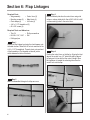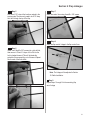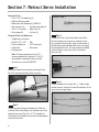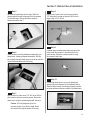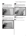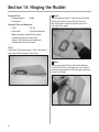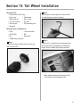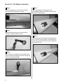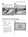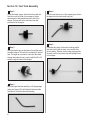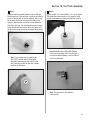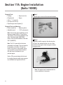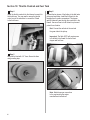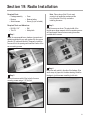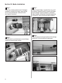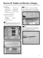
1
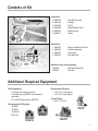
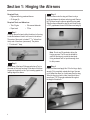
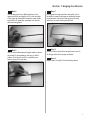
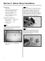
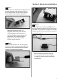
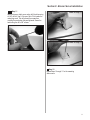
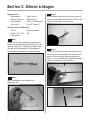
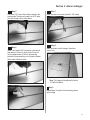
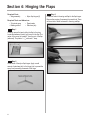
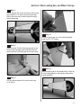
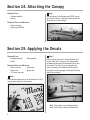
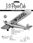
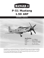
®
TM
WE GET PEOPLE FLYING
P-51 Mustang
1.50 ARF
ASSEMBLY MANUAL
Specifications
Wingspan: ..............
Length: ....................
Wing Area:.............
Weight: ...................
Engine:.....................
Radio: ......................
77 in (1956mm)
68 in (1727mm)
1039 sq in (67.03sq dm)
13–14 lb (5.89–6.34 kg)
1.20–2.00 4-stroke
6-channel w/10 servos
Congratulations on your purchase of the Hangar 9® P-51 Mustang ARF. This sport scale model warbird is intended for
the modeler wanting to experience the thrill of being a Fighter Ace in the European Theater during WW-II. The Hangar 9
P-51 is a low-wing, high-performance plane. If this is your first attempt at flying this type of aircraft, please consult a
more experienced pilot to help in the setup and initial flights.
Table of Contents
Table of Contents . . . . . . . . . . . . . . . . . . . . . . . . . . . . . . . . . . . . . . . . . . . . . . . . . . . . . . . . . . . . . . 2
Additional Required Equipment . . . . . . . . . . . . . . . . . . . . . . . . . . . . . . . . . . . . . . . . . . . . . . . . . . . . 3
Contents of Kit . . . . . . . . . . . . . . . . . . . . . . . . . . . . . . . . . . . . . . . . . . . . . . . . . . . . . . . . . . . . . . . . 3
Additional Required Tools and Adhesives . . . . . . . . . . . . . . . . . . . . . . . . . . . . . . . . . . . . . . . . . . . . . 4
Other Items Needed (not included in the kit) . . . . . . . . . . . . . . . . . . . . . . . . . . . . . . . . . . . . . . . . . . 4
Warning . . . . . . . . . . . . . . . . . . . . . . . . . . . . . . . . . . . . . . . . . . . . . . . . . . . . . . . . . . . . . . . . . . . . . 4
Warranty Information . . . . . . . . . . . . . . . . . . . . . . . . . . . . . . . . . . . . . . . . . . . . . . . . . . . . . . . . . . . . 5
Using the Manual . . . . . . . . . . . . . . . . . . . . . . . . . . . . . . . . . . . . . . . . . . . . . . . . . . . . . . . . . . . . . . 5
Before Starting Assembly . . . . . . . . . . . . . . . . . . . . . . . . . . . . . . . . . . . . . . . . . . . . . . . . . . . . . . . . 5
Section 1: Hinging the Ailerons . . . . . . . . . . . . . . . . . . . . . . . . . . . . . . . . . . . . . . . . . . . . . . . . . . . . 6
Section 2: Aileron Servo Installation . . . . . . . . . . . . . . . . . . . . . . . . . . . . . . . . . . . . . . . . . . . . . . . . 8
Section 3: Aileron Linkages . . . . . . . . . . . . . . . . . . . . . . . . . . . . . . . . . . . . . . . . . . . . . . . . . . . . . . 12
Section 4: Hinging the Flaps . . . . . . . . . . . . . . . . . . . . . . . . . . . . . . . . . . . . . . . . . . . . . . . . . . . . . 14
Section 5: Flap Servo Installation . . . . . . . . . . . . . . . . . . . . . . . . . . . . . . . . . . . . . . . . . . . . . . . . . 16
Section 6: Flap Linkages . . . . . . . . . . . . . . . . . . . . . . . . . . . . . . . . . . . . . . . . . . . . . . . . . . . . . . . . 20
Section 7: Retract Servo Installation . . . . . . . . . . . . . . . . . . . . . . . . . . . . . . . . . . . . . . . . . . . . . . . . 22
Section 8: Main Landing Gear and Wheel Doors . . . . . . . . . . . . . . . . . . . . . . . . . . . . . . . . . . . . . . 24
Section 9: Joining the Wing . . . . . . . . . . . . . . . . . . . . . . . . . . . . . . . . . . . . . . . . . . . . . . . . . . . . . 28
Section 10: Mounting the Wing to the Fuselage . . . . . . . . . . . . . . . . . . . . . . . . . . . . . . . . . . . . . . . 31
Section 11: Lower Air Intake Installation . . . . . . . . . . . . . . . . . . . . . . . . . . . . . . . . . . . . . . . . . . . . 32
Section 12: Stabilizer Installation . . . . . . . . . . . . . . . . . . . . . . . . . . . . . . . . . . . . . . . . . . . . . . . . . . 34
Section 13: Hinging the Elevators . . . . . . . . . . . . . . . . . . . . . . . . . . . . . . . . . . . . . . . . . . . . . . . . . 36
Section 14: Hinging the Rudder . . . . . . . . . . . . . . . . . . . . . . . . . . . . . . . . . . . . . . . . . . . . . . . . . . . 38
Section 15: Tail Wheel Installation . . . . . . . . . . . . . . . . . . . . . . . . . . . . . . . . . . . . . . . . . . . . . . . . . 39
Section 16: Fuel Tank Assembly . . . . . . . . . . . . . . . . . . . . . . . . . . . . . . . . . . . . . . . . . . . . . . . . . . 41
Section 17A: Engine Installation (Saito 180GK) . . . . . . . . . . . . . . . . . . . . . . . . . . . . . . . . . . . . . . . 44
Section 17B: Engine Installation (Saito 200 TI) . . . . . . . . . . . . . . . . . . . . . . . . . . . . . . . . . . . . . . . 46
Section 18: Throttle Pushrod and Fuel Tank . . . . . . . . . . . . . . . . . . . . . . . . . . . . . . . . . . . . . . . . . . 49
Section 19: Radio Installation . . . . . . . . . . . . . . . . . . . . . . . . . . . . . . . . . . . . . . . . . . . . . . . . . . . . 51
Section 20: Rudder and Elevator Linkages . . . . . . . . . . . . . . . . . . . . . . . . . . . . . . . . . . . . . . . . . . . 53
Section 21: Throttle Linkage Installation . . . . . . . . . . . . . . . . . . . . . . . . . . . . . . . . . . . . . . . . . . . . 57
Section 22: Attaching the Cowl . . . . . . . . . . . . . . . . . . . . . . . . . . . . . . . . . . . . . . . . . . . . . . . . . . . 58
Section 23: Cockpit Details . . . . . . . . . . . . . . . . . . . . . . . . . . . . . . . . . . . . . . . . . . . . . . . . . . . . . . 58
Section 25: Applying the Decals . . . . . . . . . . . . . . . . . . . . . . . . . . . . . . . . . . . . . . . . . . . . . . . . . . 60
Section 24: Attaching the Canopy . . . . . . . . . . . . . . . . . . . . . . . . . . . . . . . . . . . . . . . . . . . . . . . . . 60
Adjusting the Engine . . . . . . . . . . . . . . . . . . . . . . . . . . . . . . . . . . . . . . . . . . . . . . . . . . . . . . . . . . . 61
Control Throws and Center of Gravity . . . . . . . . . . . . . . . . . . . . . . . . . . . . . . . . . . . . . . . . . . . . . . 61
Preflight at the Field . . . . . . . . . . . . . . . . . . . . . . . . . . . . . . . . . . . . . . . . . . . . . . . . . . . . . . . . . . . 61
2
Contents of Kit
B
F
C
E
Large Parts
A. HAN2401
B. HAN2404
C. HAN2402
D. HAN2405
E. HAN2406
F. HAN2407
Wing Set with Joiner
Fuselage
Tail Set
Fiberglass Belly Scoop
Fiberglass Cowl
Canopy
Small Parts
1. HAN2403
2. HAN2409
3. HAN2410
4. HAN2412
Aluminum Stabilizer Tube Set
Tail Wheel Assembly
Pushrod Set
Scale Detail Set
A
D
1
3
4
Additional items sold separately
HAN2408
Mechanical Retract Set
HAN2411
Decal Set
2
Additional Required Equipment
Radio Equipment
• 6-channel radio system (minimum)
• 8 standard servos (JRPS537 recommended or
equivalent)
• 2 Low-Profile Retract Servos (JRPS703)
Recommended JR Systems
• JR XF652
• JR XP783
• JR XP8103
• PCM 10X
JR PCM 10X
Recommended Engines
• 1.50–2.18 2-cycle engines
• 1.20–2.00 4-cycle engines
4-Cycle Engine
• Saito™ 1.80–2.00
Saito 1.80
SAIE180
JR XP8103
Saito 200Ti
SAIE200TI
3
Additional Required Tools and Adhesives
Tools
• Drill
• Drill Bits: 1/16", 1/8", 3/32", 5/64”, 5/32"
• Phillips screwdriver (small, medium)
• Pliers
• Side Cutters
• Moto-tool w/cut-off wheel
• Hobby knife with #11 blade
• 90-degree triangle
• Straight edge
• Canopy scissors
• Side cutters
• Adjustable wrench
• Hex wrench
Other Required Items
• Mixing sticks for epoxy
• Epoxy brushes
• Rubbing alcohol
• Sanding bar
• Sandpaper (medium)
• Paper towels
• Wax paper
• Felt-tipped pen or pencil
• Measuring device (e.g. ruler, tape measure)
• T-pins
• String
• Radio packing foam
• Petroleum jelly
Adhesives
• Thin CA (cyanoacrylate) glue
• Thick CA (cyanoacrylate) glue
• CA remover/debonder
• 6-minute epoxy
• 30-minute epoxy
• Pacer Z-42 Threadlock
• Canopy glue (RC-56)
• Masking tape (3M blue recommended)
Other Items Needed (not included in the kit)
• Propeller (consult your engines instruction manual)
• 24” Servo Lead Extension (JRPA102)
• 6” Servo Lead Extension (JRPA094)
• Large servo arm (JRPA212) (2)
• Propeller (consult your engines instruction manual)
• 5" P-51 Spinner
Warning
An RC aircraft is not a toy! If misused, it can cause serious bodily harm and damage to property. Fly only in open areas,
preferably at AMA (Academy of Model Aeronautics) approved flying sites, following all instructions included with your
radio and engine.
4
Before Starting Assembly
Before beginning the assembly of your P-51, remove each part from its bag for inspection. Closely inspect the
fuselage, wing panels, rudder, and stabilizer for damage. If you find any damaged or missing parts, contact the
place of purchase.
If you find any wrinkles in the covering, use a heat gun or covering iron to remove them. Use caution while working
around areas where the colors overlap to prevent separating the colors.
Using the Manual
This manual is divided into sections to help make assembly easier to understand, and to provide breaks between
each major section. In addition, check boxes have been placed next to each step to keep track of each step
completed. Steps with two boxes indicate that the step will require repeating, such as for a right or left wing panel,
two servos, etc. Remember to take your time and follow the directions.
Warranty Information
Horizon Hobby, Inc. guarantees this kit to be free from defects in both material and workmanship at the date of
purchase. This warranty does not cover any parts damage by use or modification. In no case shall Horizon Hobby's
liability exceed the original cost of the purchased kit. Further, Horizon Hobby reserves the right to change or modify
this warranty without notice.
In that Horizon Hobby has no control over the final assembly or material used for the final assembly, no liability
shall be assumed nor accepted for any damage of the final user-assembled product. By the act of using the product,
the user accepts all resulting liability.
Once assembly of the model has been started, you must contact Horizon Hobby, Inc. directly regarding any warranty
question that you have. Please do not contact your local hobby shop regarding warranty issues, even if that is where
you purchased it. This will enable Horizon to better answer your questions and service you in the event that you may
need any assistance.
If the buyer is not prepared to accept the liability associated with the use of this product, the buyer is advised to
return this kit immediately in new and unused condition to the place of purchase.
Horizon Hobby
4105 Fieldstone Road
Champaign, Illinois 61822
(217) 355-9511
www.horizonhobby.com
5
Section 1: Hinging the Ailerons
Required Parts
• Right and left wing panels w/ailerons
• CA hinges (6)
Required Tools and Adhesives
• Thin CA glue
• CA remover/debonder
• Paper towel
• T-Pins
Step 3
Slide the aileron onto the wing until there is only a
slight gap between the aileron and wing panel. Remove
the T-pins and snug the aileron against the wing panel.
Slide the aileron towards the wing tip until there is only
a 1/32" gap between the end of the aileron and wing tip.
Step 1
Carefully remove the tape holding the aileron to the wing.
Locate the hardwood control horn mount in the aileron.
The center of the mount is located 7 11/16" inches from
the tip end of the aileron (narrow end). The plate is
1 1/4" wide and 1" deep.
Note: Do not use CA accelerator during the
hinging process. The CA must be allowed to
soak into the hinge to provide the best bond.
Using accelerator will not provide enough time
for this process.
Step 2
Locate three of the large CA hinges and place a T-pin in
the center of the hinge as shown. Slide each of the three
hinges into the aileron so the T-pin is resting against the
leading edge of the aileron.
6
Step 4
Deflect the aileron and apply thin CA to the hinge. Apply
enough CA to completely saturate the hinge. Use care
not to deflect the aileron so it pulls away from the wing.
When the hinge is glued in place, there should be no
more than a 1/32" hinge gap maintained throughout
the length of the aileron.
Section 1: Hinging the Ailerons
Step 5
Turn the wing panel over, deflect the aileron in the
opposite direction and apply thin CA to the other side
of the hinges as described in the previous step. Make
sure the thin CA penetrates completely into both the
aileron and wing panel.
Step 7
Firmly grasp the wing and aileron and gently pull on
the aileron to ensure the hinges are secure and cannot
be pulled apart. Use caution when gripping the wing
and aileron to avoid crushing the structure.
Step 6
Use CA remover/debonder and a paper towel to remove
any excess CA accumulated on the wing or aileron
surface. Allow time for the CA to completely cure
before moving to the next step.
Step 8
Work the aileron up and down several times to work in
the hinges and check for proper movement.
Step 9
Repeat Steps 1 through 8 for the remaining aileron.
7
Section 2: Aileron Servo Installation
Required Parts
• Wing assembly
• Aileron servos w/mounting hardware (2)
• Servo hatch screws (#2 x 3/8") (4)
• Large Servo Arm (JRPA212) (1 pkg)
• Servo mounting blocks (4)
• 24" Servo Lead Extension (JRPA102)
• Aileron servo hatch (2)
Step 2
Install the recommended servo hardware (grommets and
eyelets) supplied with the servo. Temporarily install a
long half servo arm (JRPA212) onto the servo and
position the servo onto the hatch so the servo arm is
centered in the notch. Also ensure the servo arm does not
extend past the edge of the servo hatch. Once satisfied,
mark the location for the servo mounting blocks.
Required Tools and Adhesives
• Phillips screwdriver • Felt-tipped pen
• String/dental floss
• Ruler
• Drill Bit: 1/16", 5/64" • Drill
• 6-minute epoxy
Step 1
Locate the aileron hatch. The slot for the aileron horn is
positioned towards the trailing edge of the wing and
towards the wing tip as shown.
Note: The aileron servo is mounted directly
to the hatch.
8
Step 3
Locate the servo mounting blocks. Use 6-minute
epoxyto glue them in place on the marks made in
the previous step. Let the epoxy fully cure before
proceeding to the next step.
Section 2: Aileron Servo Installation
Step 4
Place the aileron servo between the mounting blocks and
use a felt-tipped pen to mark the location of the four
servo mounting screws. Note that the servo must not
touch the hatch in order to isolate engine vibration.
Note: Before mounting the servo, it is
suggested to electronically center the servo
using the transmitter, then install the servo
arm to avoid having to remove the servo and
center the arm later. It may be necessary to
slightly trim one of the servo mounting
blocks to clear the servo wire.
Photo for Step 5
Step 6
Connect a 24" Servo Lead extension (JRPA212) to the
servo lead. Secure the connectors by tying them in a knot
using dental floss (as shown) or by using a commercially
available connector clamp to prevent the servo leads from
becoming disconnected.
Step 5
Remove the servo and use a 1/16" drill bit to predrill
the holes for the servo mounting screws marked in the
previous step. Use the screws supplied with the servo
to mount it to the servo mounting blocks.
Note: It is always a good idea to secure the
servo connector and servo extension together
to prevent the wires from becoming unplugged
inside the wing.
9
Section 2: Aileron Servo Installation
Step 7
Use a piece of string with a small weight (such as a wheel
collar) attached as a device to pull the servo lead through
the wing. Lower the weight through the opening at the
root of the wing as shown.
Photo for Step 9
Step 8
Stand the wing on the tip and allow the weight to drop
through the wing until it appears in the opening for the
servo leads. It may require a little help to pass by the
wing ribs in the form of slightly shaking the wing.
Photo for Step 9
Step 10
Place the hatch cover in position in the aileron opening.
Measure in 1/8" on all four sides of the hatch. Drill four
1/16" holes at the intersections of the lines as shown.
Note: Drill through the servo hatch and the
underlying hatch mounts. Use caution not to
accidentally drill through the top of the wing.
Step 9
Tie the string onto the servo extension. Gently pull the
extension through the wing using the string. Untie the
string when the servo lead has been pulled through. Use
tape to secure the servo lead to the wing to prevent it
from falling back into the wing panel.
10
Section 2: Aileron Servo Installation
Step 11
Remove the servo hatch cover and re-drill the holes using
a 5/64" drill bit. Use 2–3 drops of thin CA to harden the
underlying wood. This will prevent the screws from
crushing the wood when they are tightened. Secure the
hatch using four #2 x 3/8" screws.
Photo for Step 11
Photo for Step 11
Step 12
Repeat Steps 1 through 11 for the remaining
aileron servo.
11
Section 3: Aileron Linkages
Required Parts
• Wing assembly
• Mounting screws (6)
• Clevis keeper (4)
• 4-40 nuts (4)
• Control horn (2)
• Metal clevis (4)
• 4-40 x 2" threaded rod (2)
• #2 x 3/8" screws (6)
Step 3
Remove the back plate from the control horn using side
cutters or a sharp hobby knife. Use a 5/64" drill bit to drill
out the mounting holes in the control horn.
Required Tools and Adhesives
• Thin CA
• Phillips screwdriver
• Drill Bit: 1/16", 5/64" • Drill
• Felt-tipped pen
Step 1
Prepare the 4-40 aileron linkage by placing the clevis
keepers onto the metal clevises. Thread a 2-56 nut onto
each end of the 4-40 x 2" threaded rod. Thread a clevis
onto each end of the threaded rod. The threaded rod
should just be visible between the forks of the clevis.
Step 2
Attach the assembled control linkage to the
aileron servo arm.
12
Step 4
Position the control on the aileron by aligning the holes
of the control horn with the hinge line of the aileron and
center on the horn mounting plate (as marked back in
Section 1). Use a felt-tipped pen to transfer the mounting
holes from the control horn onto the aileron.
Section 3: Aileron Linkages
Step 5
Drill three 1/16" holes at the locations marked in the
previous step. The holes only need to be 5/16" deep;
don’t drill through the top of the aileron.
Step 6
Install one of the #2 x 3/8" screws into a hole drilled,
then remove it. Place 2-3 drops of thin CA into the
hole to harden the wood. This will eliminate the
potential of the screw pulling out of the wood. Repeat
this for each of the three holes.
Step 7
Attach the control horn using three #2 x 3/8" screws.
Step 8
Attach the aileron control linkage to the aileron
control horn.
Note: The linkage will be adjusted in Section
18: Radio Installation
Step 9
Repeat Steps 1 through 8 for the remaining aileron
servo linkage.
13
Section 4: Hinging the Flaps
Required Parts
• Wing assembly
• Nylon flap hinges (6)
Required Tools and Adhesives
• 30-minute epoxy
• Paper towels
• Rubbing alcohol
• Petroleum jelly
Step 1
Carefully remove the tape holding the flap to the wing.
Locate the hardwood control horn mount in the flap. The
center of the mount is located 5" from the root of the flap
(wide end). The plate is 1 1/4" wide and 1" deep.
Step 2
Locate three of the nylon flap hinges. Apply a small
amount of petroleum jelly to the hinge joint to prevent the
epoxy from preventing movement of the hinge.
14
Step 3
Locate the holes in the wing and flap for the flap hinges.
Remove the covering if necessary from each hole. There
will be a total of three holes each in the wing and flap.
Section 4: Hinging the Flaps
Step 4
Install the hinges in the flap and slide the flap into
position. Check to make sure the flap aligns with
both the aileron and wing trailing edge. If it does not,
enlarge the first 1/4" of the hinge holes in both the
wing and flap to provide more clearance for the center
of the hinge. This will allow the flap to be positioned
closer to the wing for alignment.
Step 5
Use 30-minute epoxy to install the hinges. Apply epoxy
to both the holes in the flap and wing using a toothpick.
Apply a light coat of epoxy to the hinge. Slide the flap
into position, and move it up and down to make sure the
hinges are aligned. Use tape around the division between
the flap and wing, as well as the flap and aileron, to hold
the flap until the epoxy fully cures.
Step 6
Repeat Steps 1 through 5 for the remaining flap.
15
Section 5: Flap Servo Installation
Required Parts
• Wing assembly
• Flap servos w/mounting hardware (2)
• Servo hatch screws (#2 x 3/8") (4)
• Large Servo Arm (JRPA212) (1 pkg)
• Servo mounting blocks (4)
• 6" Servo Lead Extension (JRPA094)
• Flap servo hatch (2)
Required Tools and Adhesives
• Thin CA
• Thick CA
• Phillips screwdriver • Felt-tipped pen
• Drill Bit: 1/16", 5/64" • Drill
• String/.dental floss
Step 1
Locate the flap hatch. The slot for the flap horn is
positioned towards the trailing edge of the wing, as
well as towards the tip, as shown in the photo.
16
Step 2
Install the recommended servo hardware (grommets and
eyelets) supplied with the servo. Temporarily install a
long half servo arm (JRPA212) onto the servo and
position the servo onto the hatch so the servo arm is
centered in the notch. Also ensure the servo arm does not
extend past the edge of the servo hatch. Once satisfied,
mark the location for the servo mounting blocks.
Section 5: Flap Servo Installation
Step 3
Locate the servo mounting blocks. Use 6-minute
epoxyto glue them in place on the marks made in
the previous step. Let the epoxy fully cure before
proceeding to the next step.
Step 4
Place the flap servo between the mounting blocks
and use a felt-tipped pen to mark the location of the
four mounting screws.
Note: The servo must not touch the hatch in
order to isolate engine vibration.
Step 5
Remove the servo and use a 1/16" drill bit to predrill
the holes for the servo mounting screws marked in the
pervious step. Use the screws supplied with the servo
to mount it to the servo mounting blocks.
Step 6
Before installing the servo arm, center the servo
electronically using the transmitter. Install the servo
arm so it is positioned towards the rear of the servo
hatch (trailing edge) when the transmitter is in the “up
flap” position. Check the movement of the servo, then
install the servo arm screw.
17
Section 5: Flap Servo Installation
Step 7
Connect a 6" Servo Lead extension (JRPA094) to the
servo lead. Secure the connectors by tying them in a
knot using dental floss (as shown) or by using a
commercially available connector clamp to prevent
the servo leads from becoming disconnected.
Note: It is always a good idea to secure the
servo connector and servo extension together
to prevent the wires from becoming unplugged
inside the wing.
Step 8
Use a piece of string with a small weight (such as a
wheel collar) attached as a device to pull the servo lead
through the wing. Lower the weight through the opening
at the root of the wing as shown.
18
Step 9
Stand the wing on the tip and allow the weight to drop
through the wing until it appears in the opening for the
servo leads. It may require a little help to pass by the
wing ribs in the form of slightly shaking the wing.
Step 10
Tie the string onto the servo extension. Gently pull the
extension through the wing using the string. Untie the
string when the servo lead has been pulled through. Use
tape to secure the servo lead to the wing to prevent it
from falling back into the wing panel.
Section 5: Flap Servo Installation
Step 11
Place the hatch cover into position in the flap opening.
Measure in 1/8" on all four sides of the hatch. Drill four
1/16” holes at the intersections of the lines as shown.
Step 12
Remove the servo hatch cover and re-drill the holes using
a 5/64" drill bit. Use 2–3 drops of thin CA to harden the
underlying wood. This will prevent the screws from
crushing the wood when they are tightened. Secure the
hatch using four #2 x 3/8" screws.
Note: Drill through the servo hatch and the
underlying hatch mounts. Use caution not to
accidentally drill through the top of the wing.
Step 13
Repeat Steps 1 through 12 for the remaining flap servo.
19
Section 6: Flap Linkages
Required Parts
• Wing assembly
• Control horn (2)
• Mounting screws (6) • Metal clevis (4)
• Clevis keeper (4)
• 4-40 nuts (4)
• 4-40 x 1-1/2" threaded rod (2)
• #2 x 3/8” screws (6)
Step 3
Remove the back plate from the control horn using side
cutters or a sharp hobby knife. Use a 5/64" drill bit to drill
out the mounting holes in the control horn.
Required Tools and Adhesives
• Thin CA
• Phillips screwdriver
• Drill Bit: 1/16", 5/64" • Drill
• Felt-tipped pen
Step 1
Prepare the flap linkage by placing the clevis keepers onto
the metal clevises. Thread a 4-40 nut onto each end of the
4-40 x 1-1/2" threaded rod. Thread a clevis onto each end
of the threaded rod. The threaded rod should just be
visible between the forks of the clevis.
Step 2
Attach the assembled linkage to the flap servo arm.
20
Step 4
Position the control horn on the flap by: Aligning the front
edge of the control horn 1/2" behind the trailing edge of
the wing and in-line with the flap control linkage. Use a
felt-tipped pen to transfer the mounting holes from the
control horn onto the flap.
Section 6: Flap Linkages
Step 5
Drill three 1/16" holes at the locations marked in the
previous step. The holes only need to be 5/16" deep;
don’t drill through the top of the flap.
Step 7
Attach the control horn using three #2 x 3/8" screws.
Step 8
Attach the flap control linkage to the flap control horn.
Step 6
Install one of the #2 x 3/8" screws into a hole drilled,
then remove it. Place 2–3 drops of thin CA into the
hole to harden the wood. This will eliminate the
potential of the screw pulling out of the wood. Repeat
this for each of the three holes.
Note: The linkage will be adjusted in Section
18: Radio Installation.
Step 9
Repeat Steps 1 through 8 for the remaining flap
servo linkage.
21
Section 7: Retract Servo Installation
Required Parts
• 4-40 x 10-1/2" threaded rod (2)
• Right and left wing panels
• Retract servo with hardware (2) (JRPS703)
• Easy connector (2)
• Connector back plate (2)
• 4-40 x 1/4" screw (2) • Metal clevis (2)
• Clevis keeper (2)
• 4-40 nut (2)
Required Tools and Adhesives
• Threadlocking compound
• Drill Bit: 1/16", 7/64" • Drill
• Phillips screwdriver • 3/32" hex wrench
• Hobby knife
• Side cutters
• Felt-tipped pen
Note: The retract mechanism for the P-51
comes preinstalled from Hangar 9®. The P-51
retract system is designed to use low-profile
retract servos, such as the JRPS703.
Photo for Step 5
Step 3
Connect the clevis to the retract actuator lever. Slide
the clevis keeper onto the clevis to prevent the clevis
from opening up during flight. Apply a small amount of
threadlocking compound behind the clevis, then tighten
the nut against the clevis. This will prevent the threaded
rod from rotating in the clevis, which could lead to
failure in flight.
Step 1
Remove the retract from the wing by removing the four
#2 x 3/8" screws that hold the retract in position.
Step 4
Cut the threaded rod to a length of 9 1/2”. Make a slight
bend as shown in the photo to make the installation of the
retract in the next step easier.
Step 2
Prepare the retract linkage by threading a 4-40nut onto
the shaft. Slide a clevis keeper onto the metal clevis, then
thread the clevis onto the 4-40 x 10 1/2" threaded rod.
The threads of the threaded rod should be visible between
the forks of the clevis.
22
Section 7: Retract Servo Installation
Step 5
Re-install the retract back into the wing. Guide the
retract pushrod through the wing and into the opening
for the retract servo. Secure the retract using the
screws removed in Step 1.
Step 6
Install the servo mounting hardware included with your
retract servo, (rubber grommets and eyelets). With the
servo wheel removed, install the servo as shown, with the
output shaft towards the root of the wing.
Step 8
Using a ruler, locate a hole in the servo arm that is
1/2” away from the center on the arm. Drill the hole
larger using a 7/64" drill bit.
Step 9
Locate an easy connecter and an easy connector back
plate. Install the connector in the hole drilled in the
previous step. Secure the connector position using
the connector back plate.
Step 10
Connect the retract servo to your radio system and
electronically move the servo to the retracted position.
Slide the retract control wire through the easy connector
as shown and secure the servo wheel to the retract servo.
Step 7
With the servo in place, use a 1/16" drill bit to drill the
pilot holes for the servo mounting screws. Secure the
retract servo using the screws supplied with the servo.
Caution: Drill only deep enough for the
mounting screws. If you drill too deep, the bit
will come out through the bottom of the wing.
23
Section 7: Retract Servo Installation
Step 11
With the retract servo in the retracted position, push the
retract linkage to manually retract the landing gear. Install
a 4-40 x 1/4" screw into the easy connector and tighten it
to secure the retract linkage.
Photo for Step 12
Photo for Step 12
Step 12
Cycle the retract system several times to make sure there
is no binding. Also check to verify the gear locks in
both the extended and retracted positions. Make any
necessary adjustments to be sure the retracts are
working and locking correctly.
Step 13
Repeat Steps 1 through 12 for the remaining retract.
Section 8: Main Landing Gear and
Wheel Doors
Required Parts
• Wing assembly
• Landing gear door (2)
• Wheel collars (4)
• M3 x 8 screw (4)
• Axle mounts (2)
• Axles (2)
• 6-32 set screw (2)
• 8-32 set screw (2)
• #4 x 7/16" screws (8)
• Main landing gear wheels (2)
• Landing gear door mounts (2)
Required Tools
• Felt-tipped pen
• Phillips screwdriver
• Drill Bit: 1/8"
• Drill
• Moto-tool w/cut-off wheel
• Threadlocking compound
24
Step 1
Slide the two landing gear door mounts onto the
landing gear strut. The position of the mounts will
be determined later.
Section 8: Main Landing Gear and Wheel Fairings
Step 2
Slide the axle mount onto the landing gear strut. Apply a
drop of thread locking compound onto a 6-32 set screw.
Secure the axle mount using the 6-32 set screw, making
sure to tighten the screw onto the flat spot on the strut.
Step 3
File a flat spot onto the axle. Slide the axle into the axle
mount. Apply a drop of thread locking compound onto an
8-32 set screw. Use the set screw to secure the axle.
Make sure to tighten the set screw onto the flat spot.
Step 4
Slide a wheel collar onto the axle. Position the wheel
collar against the axle mount, and then secure its location
using an M3 x 8 screw.
Step 5
Slide the wheel onto the axle. Make sure the wheel can
rotate freely on the axle. Slide another wheel collar onto
the axle and use an M3 x 8 screw to finish up the step.
Remember to file a flat spot on the axle, as well as use
threadlocking compound.
Step 6
Remove the excess axle beyond the wheel collar using
a Moto-tool w/cut-off wheel
25
Section 8: Main Landing Gear and Wheel Fairings
Step 7
Check the fit of the wheel in the wheel well when the
gear is retracted. Make any necessary adjustments so
the wheel does not rub the wheel well when the gear
is retracted or extended.
Step 9
Draw two small marks on the landing gear door that will
indicate the location of the landing gear strut. Mark the
landing gear where the lower edge of the landing gear
door will be positioned.
Step 8
Locate the correct landing gear door tape it into position.
The correct door will fit the contour of the airfoil and have
a small protrusion towards the leading edge of the wing.
Step 10
Remove the landing gear door and draw a line connecting
the two marks on the back of the door.
26
Section 8: Main Landing Gear and Wheel Fairings
Step 11
Position the gear door mounts as follows: Position mount
near the wheel so it is almost touching the wheel well.
Position the mount near the retract mechanism slightly
below the wheel well.
Photo for Step 14
Step 15
Secure the landing gear door to the mounting brackets
using four #4 x 7/16" screws.
Step 12
Extend the retract. Position the landing gear door so the
centerline and lower edge marks are aligned. Mark the
screw locations for the landing gear door mount screws.
Step 16
Move the landing gear to the retracted position. Check the
fit of the landing gear door and make any adjustments to
provide a perfect fit.
Step 14
Drill the locations marked in the previous step using
a 1/8" drill bit.
27
Section 8: Main Landing Gear and Wheel Fairings
Step 17
Once the landing gear door has been adjusted, move
the retracts to the extended position. Apply a few drops
of thin CA to the mounts to lock in their positions on
the landing gear strut.
Step 18
Apply a few drops of thick CA to the screws to prevent
them from loosening during flight. You may also want to
trim off the excess screw for a cleaner look.
Step 19
Repeat Steps 1 through 18 for the remaining retract.
Section 9: Joining the Wing
Required Parts
• Wing assembly
• Wing dowels (2)
• Wing joiner
Required Tools and Adhesives
• Ruler
• Masking Tape
• 5-minute epoxy
• 30-minute epoxy
• Rubbing alcohol
• Paper towels
Step 1
Locate the two 1/4" x 2" wing dowels. Draw a line 5/8"
from one end on each dowel.
28
Step 2
Glue the dowel into the wing using 5-minute epoxy. Apply
epoxy to both the holes in the wing and dowels. Slide the
dowels in up to the line drawn in the previous step. Clean
up any excess epoxy using a paper towel and rubbing
alcohol. Allow the epoxy to fully cure before proceeding.
Section 9: Joining the Wing
Step 3
Locate the wing joiner and mark a centerline on the joiner.
Step 5
With the wing panels together, check for correct
dihedral. Place the wing on a large flat surface with
one panel resting flat on the surface. The opposite
wing tip should be 7 3/8" from the work surface.
Once satisfied with the fit, separate the wing panels
and remove the wing joiner.
Step 4
Without using any glue, test the fit of the wing panels and
wing joiner. The panels must fit together without any
gaps, top or bottom. If any gaps do exist, use a sanding
bar to lightly sand the root ribs of both panels until the
panels fit together perfectly.
Note: Read through the remaining steps of
this section before mixing any epoxy.
Hint: It is extremely important to use plenty of
epoxy when joining the wing panels. It will
also be helpful to use wax paper under the
wing joint to avoid gluing the wing to your
work surface.
Step 6
Mix approximately 1 ounce of 30-minute epoxy. Using an
epoxy brush, apply a generous amount of epoxy to the
wing joiner cavity of one wing panel.
29
Section 9: Joining the Wing
Step 7
Completely coat one half of the wing joiner with epoxy up
to the line drawn in Step 1. Be sure to apply epoxy to the
top and bottom of the joiner also. Insert the epoxy coated
side of the joiner into the wing joiner cavity up to the
mark on the joiner. If you have used enough epoxy, it will
ooze out of the cavity as the joiner is installed.
Step 8
Apply a generous amount of epoxy to the joiner cavity of
the opposite wing panel.
Step 9
Apply epoxy to the exposed portion of the wing joiner.
30
Step 10
Apply epoxy to root wing rib of both panels.
Step 11
Carefully slide the wing panels together. Apply enough
pressure to firmly seat the two wing panels together,
causing any excess epoxy to ooze out from between the
panels. Use rubbing alcohol and a paper towel to remove
the excess epoxy. Check to make sure there are no visible
gaps between the panels.
Step 12
Use masking tape to securely hold the wing panels
together. Place the wing assembly back onto the work
surface (covered with wax paper) and check the dihedral
angle. Allow the epoxy to fully cure before continuing
to the next section.
Section 10: Mounting the Wing to
the Fuselage
Required Parts
• Assembled wing
• Fuselage
• Plywood wing bolt plate (2)
• 1/4-20 x 2" nylon bolts (2)
Step 3
Mix 1/2 ounce of 6-minute epoxy and coat both the wing
and plywood plate. Align the plate back onto the wing and
clamp it in position. Remove any excess epoxy using
paper towels and rubbing alcohol.
Required Tools and Adhesives
• 6-minute epoxy
• Screwdriver (slotted)
• Hobby knife
• Felt-tipped pen
Step 1
Locate the plywood wing bolt plate. Align the plate along
the centerline of the wing and trailing edge. Trace around
the plate using a felt-tipped pen.
Caution: Use scrap plywood under the clamps
to prevent damage to the balsa wing structure.
Step 4
Once the epoxy has fully cured, repeat Steps 1 through 3
for the remaining wing bolt plate.
Hint: The hole in the wing and hole in the
plate should line up when positioned correctly.
Step 2
Use a hobby knife with a brand new blade to remove
the covering 1/16" inside of the line drawn. Use care
not to cut into the underlying balsa, as this will
weaken the wing structure.
Step 5
Place the wing onto the fuselage, and check the fit. Make
any adjustments necessary to the wing bolt holes and
attach the wing using the two 1/4-20 x 2" nylon bolts.
31
Section 11: Lower Air Intake Installation
Required Parts
• Air scoop
• Plastic guide tubes (2)
• Plywood tube locators (2)
Step 3
Place a piece of wax paper between the fuselage and
wing, then bolt the wing onto the fuselage.
Required Tools and Adhesives
• Medium CA
• Thick CA
• Razor saw
• Hobby knife
• Felt-tipped pen
• Medium grit sandpaper
Step 1
Use a felt-tipped pen to trace around the heads of
the wing bolts.
Step 4
Use medium grit sandpaper to lightly sand the inside
edge of the air scoop.
Step 2
Remove the wing bolts from the wing. Locate the
plywood tube locators and use medium CA to glue the
locators in position. Use the lines drawn around the
bolt heads as a guide.
32
Section 11: Lower Air Intake Installation
Step 5
Position the air scoop onto the wing bolt plates. It
should fit snug onto the plates. Remove the air scoop,
and apply a thin bead of medium CA around the bottom
edge of the air scoop. Place it back into position and
allow the CA to cure before proceeding.
Step 6
Remove the wing from the fuselage.Try to keep the wing
bolts in the wing. Once the wing is removed, slide the
plastic guide tubes through the scoop and over the heads
of the wing bolts. The ends of the tubes will lock into the
plywood tube locators when fully installed.
Step 7
Remove the wing bolts from the plane by sliding them out
through the tubes. Remove the tubes and roughen them
using medium sandpaper.
Step 8
Apply a thin bead of thick CA around one end of the
tubes. Slide the tube in position through the air scoop
and into the plywood tube locators. Use a paper towel
to clean up any excess CA from the air scoop.
33
Section 11: Lower Air Intake Installation
Step 9
Remove the excess tube using a razor saw and
hobby knife.
Section 12: Stabilizer Installation
Required Parts
• Fuselage
• Stabilizer (right and left)
• Stabilizer tube (short) • Stabilizer tube (long)
• #2 x 3/8" screw (2)
Required Tools
• Drill Bit: 3/32"
• Phillips screwdriver
34
• Drill
Step 1
Locate both of the stabilizer tubes, short and long. Slide
the tubes into one half of the stabilizer as follows: short
tube towards the leading edge and the long tube towards
the trailing edge.
Section 12: Stabilizer Installation
Step 2
Slide the tubes into the fuselage. The hole in the stabilizer
faces the bottom of the plane.
Step 4
Use a 3/32" drill bit to drill through the hole in the
stabilizer into the stabilizer tube. Be very careful to only
drill through the tube, not through the top of the stabilizer.
Step 3
Slide the remaining stabilizer half onto the tubes.
Step 5
Secure the tube in the one stab half using a
#2 x 3/8" screw.
Step 6
Repeat Steps 4 and 5 for the remaining stab half.
35
Section 13: Hinging the Elevators
Required Parts
• Stabilizer
• CA hinges (6)
• Elevator (right and left)
Required Tools and Adhesives
• T-Pins
• Thin CA
• Paper towels
• CA remover/debonder
Step 3
Slide the elevator onto the stabilizer until there is only
a slight gap between the stabilizer and elevator. Remove
the T-pins and snug the elevator against the stabilizer.
Position the elevator so the tip aligns with the tip
of the stabilizer.
Step 1
Locate the hardwood control horn mount in the elevator.
The mount is located at the root end, and is 1 9/16"
long and 7/8" wide. This plate must be located towards
the bottom of the plane.
Note: Do not use CA accelerator during the
hinging process. The CA must be allowed to
soak into the hinge to provide the best bond.
Using accelerator will not provide enough time
for this process.
Step 2
Locate three of the large CA hinges and place a T-pin in
the center of the hinge as shown. Slide each of the three
hinges into the elevator so the T-pin is resting against the
leading edge of the elevator.
36
Step 4
Deflect the elevator and apply thin CA to the hinge.
Apply enough CA to completely saturate the hinge. Use
carenot to deflect the elevator so it pulls away from
the stabilizer. When the hinge is glued in place, there
should be no more than a 1/32” hinge gap maintained
throughout the length of the elevator.
Section 13: Hinging the Elevators
Step 5
Turn the fuselage over, deflect the elevator in the
opposite direction, and apply thin CA to the other
side of the hinges as described in the previous step.
Make sure the thin CA penetrates completely into
both the elevator and stabilizer.
Step 7
Firmly grasp the elevator and stabilizer and gently pull
them apart to ensure the hinges are secure and cannot be
pulled apart. Use caution when gripping them to avoid
crushing the structure.
Step 6
Use CA remover/debonder and a paper towel to remove
any excess CA accumulated on the stabilizer or elevator
surface. Allow time for the CA to completely cure before
moving to the next step.
Step 8
Work the elevator up and down several times to work in
the hinges and check for proper movement.
Step 9
Repeat Steps 1 through 8 for the remaining elevator.
37
Section 14: Hinging the Rudder
Required Parts
• Fuselage assembly
• CA hinges (3)
• Rudder
Required Tools and Adhesives
• T-Pins
• Thin CA
• Paper towels
• CA remover/debonder
Step 2
Slide the rudder onto the fin. Align the top of the rudder
with the top of the fin. Remove the T-pins and use
thin CA to glue the hinges into position. Apply CA to
both sides of the hinges.
Note: Hinging the rudder follows the same
procedure as hinging the ailerons and
elevators. We’ll save you some reading and
condense this into just a few steps.
Step 1
Locate three CA hinges and place a T-pin in the center of
each hinge. Slide the hinges into the rudder.
Step 3
Clean up any excess CA using CA remover/debonder.
Once the CA has fully cured, gently pull on the rudder to
ensure the hinges are secure. Flex the rudder a few times
to work in the hinges.
38
Section 15: Tail Wheel Installation
Required Parts
• Pushrod wire (33-5/8" long)
• Nylon clevis
• Clevis keeper
• Wheel collar (2)
• M3 x 8 screw
• #2 x 3/8" screw (4)
• Tail wheel
• Wire tail gear
• Tail gear steering arm
• Tail wheel
Step 2
File a flat spot on the tail gear wire. Position the flat
off-center slightly as shown in the photo.
Required Tools and Adhesives
• Pliers
• 1.5mm hex wrench
• Drill Bit: #20
• Drill
• File
• Side cutters
• Threadlocking compound
Step 1
Locate the tail wheel. Carefully drill the hole for the
axle using a #20 drill.
Step 3
Install the 33 5/8" pushrod wire into the pushrod tube
shown. Make sure the threaded end is installed first,
leaving the non-threaded end inside the radio area.
Hint: Install the pushrod wire through the hole
in the firewall to avoid bending the wire.
39
Section 15: Tail Wheel Installation
Step 4
Slide a clevis keeper onto a nylon clevis. Thread the
clevis onto the wire a minimum of 10 turns.
Step 7
Position the steering arm in the center of the
pre-installed tail gear mount. Make sure the set screw
in the arm is facing forward.
Step 5
Locate the tail gear steering arm. Use side cutters to
remove the outermost hole from the arm.
Step 8
Slide the tail gear wire through the mount and steering
arm. Position the wire so there is 1/2" between the top
of the mount and the first bend in the wire. Tighten the
set screw in the arm.
Step 6
Attach the clevis to the steering arm in the outer hole as
shown. Slide the clevis keeper onto the clevis to keep the
clevis from opening during flight.
40
Section 15: Tail Wheel Installation
Step 9
Slide a wheel collar onto the tail gear wire, then the tail
wheel. Finally, slide another wheel collar on, and use an
M3 x 8 screw to secure the outer collar. Use a little
threadlocking compound on the screw to prevent it from
vibrating loose in flight.
Step 10
Secure the tail gear door cover using four
#2 x 3/8" screws.
Section 16: Fuel Tank Assembly
Required Parts
• Clunk (fuel pickup)
• Metal caps (2)
• Fuel pickup tubing
• Fuel tank
• Rubber stopper
• M3 x 20 screw
• Metal tubes (short and long)
Step 1
Locate the fuel tank parts.
Required Tools and Adhesives
• Hobby knife
• Phillips screwdriver
Note: The stopper provided with the P-51
has three holes that are not bored completely
through the stopper. The holes are for the
fuel pickup, fill, and vent lines. For these
instructions only two holes will be used: one
for the fuel pickup and one for the fuel vent.
Only open the third hole if you are going to
use a separate fill line.
41
Section 16: Fuel Tank Assembly
Step 2
Locate the rubber stopper. Insert the shorter metal fuel
tube into one of the holes in the stopper so that an
equal amount of tube extends from each side of the
stopper. This tube will be the fuel tank pickup that
provides fuel to the engine.
Step 3
Slide the smaller cap over the tube on the smaller end of
the rubber stopper. This end will be inserted into the fuel
tank. The larger cap is placed on the side of the rubber
stopper that makes the cap. Loosely install the M3 x 20
screw through the center of the stopper.
Step 4
Bend the longer fuel tube carefully to a 45-degree angle
using your fingers. This will be the fuel tank vent tube.
Use care not to kink the tube while bending.
42
Step 5
Slide the vent tube into on of the remaining two holes in
the stopper from the tank (small cap) side.
Step 6
Locate the short piece of silicone fuel tubing and the
fuel tank clunk. Install the clunk onto one end of the
silicone tubing. Slide the silicone tubing (end opposite
the clunk) onto the fuel tank pickup tube (straight tube)
in the stopper.
Section 16: Fuel Tank Assembly
Step 7
Carefully insert the stopper assembly into the fuel tank.
Note the position of the vent tube; it must be up at the top
portion of the fuel tank to function properly. Also, it may
be necessary to shorten the length of the fuel pickup
tubing to make sure the clunk does not rub against the
back of the fuel tank. You should be able to turn the tank
to any attitude and the clunk will fall to the lowest point.
(All directions except for having the stopper facing down.)
Note: If you are planning on installing the
Saito 200TI, the fuel tank will be oriented
differently. Make sure the tank is built so the
vent is pointing up with the fuel tank oriented
as shown in the picture.
Step 8
Tighten the M3 x 20 screw carefully—do not over tighten.
This allows the rubber stopper to form a seal by being
slightly compressed, thus sealing the fuel tank opening.
Important: Be sure to differentiate between
the vent and fuel pickup tube. Once the tank is
mounted inside the fuselage, it will be difficult
to tell the tubes apart.
Note: The fuel tank will be installed in
a later section.
43
Section 17A: Engine Installation
(Saito 180GK)
Required Parts
• Fuselage
• Engine mount (2)
• #8 washers (8)
• Engine
• 8-32 x 1 1/4" screws (8)
Step 1
Locate the engine mount and the associated hardware.
• 8-32 nylon lock nuts (4)
• Plywood engine mount spacers (2)
Required Tools and Adhesives
• Phillips screwdriver • Measuring device
• Adjustable wrench
• 11/32" socket wrench
Note: There are two engine installations in this
instruction manual (Section 17A and Section
17B). Section 17A covers the installation of the
Saito 1.80 Golden Knight (SAIE180GK).
Section 17B covers the installation of the Saito
200 TI (SAIE200TI).
Note: The P-51 comes with the blind nuts
preinstalled in the firewall. They are located for
the installation of the Saito 1.80-size fourstrokes. If you plan on using another engine,
you may need to remove the blind nuts and
drill new holes in the firewall for your
particular engine.
Step 2
Temporarily install the engine to the rails using four
8-32 bolts, four washers and four lock nuts. Leave
the bolts loose enough to allow the engine to slide on
the engine mount.
Section 17B covers relocating the blind nuts
for mounting the engine when using an engine
mount different than supplied with the kit.
Note: The engine mount is embossed with the
correct orientation for the mounts.
44
Section 17A: Engine Installation (Saito 180GK)
Step 3
Prepare the engine mount for installation by sliding
four 8-32 bolts and washers through the engine
mount. Position the plywood engine mount spacers
onto the bolts as shown.
Step 4
Install the engine mount.
Step 5
Install the spinner back plate and propeller. Position the
engine so there is between 1/16" and 1/8" gap between
the back plate and fuselage.
Step 6
Remove the spinner back plate and tighten the screws
holding the engine to the mount. An 11/32" socket
wrench will make this task a lot easier.
45
Section 17B: Engine Installation
(Saito 200 TI)
Required Parts
• Fuselage
• #8 washers (4)
• Felt-tipped pen
• Engine
• 8-32 x 1-1/4" screws (4)
• Associated engine mount
Required Tools and Adhesives
• Phillips screwdriver • Drill
• Adjustable wrench
• Socket Wrench: 11/32"
• Drill Bit: 1/4"
• Measuring device
Step 2
If you must remove the blind nuts, thread an 8-32 bolt
partially into the nut. Lightly tap the bolt to pop the blind
nut away from the firewall. This will prevent damaging the
threads of the nuts. Trim the cross brace to allow for the
removal of the blind nuts near the top of the fuselage.
Step 1
Check the fit of the engine mount you are planning
on using. You may get lucky and not have to remove
the blind nuts.
Step 3
Measure the distance between the original holes in the
firewall. Make a mark centered right and left and top to
bottom using a felt-tipped pen.
46
Section 17B: Engine Installation (Saito 200 TI)
Important: The stock engine mount is offset
1/4" towards the top of the fuselage. Measure
1/4" towards the bottom of the fuse and make
two marks for the horizontal centerline.
Step 6
Transfer the measurements made in the last step to
the firewall. Remember to divide by two and measure
from the centerline.
Step 4
Connect the marks drawn in the previous step. Your new
engine mount will centered here the two lines cross.
Step 5
Measure and record the distance between the holes in
your particular mount. Make sure your mount will be
centered correctly when measuring.
Note: Another option is to determine the
center vertically and horizontally of your
mount. Position the mount on the centerlines
and mark the locations of the bolts directly
on the firewall.
47
Section 17B: Engine Installation (Saito 200 TI)
Step 7
Drill the locations for the new bolts using a 1/4" drill bit.
Step 9
Install any accessories that may be required for your
particular engine. In the case of the Saito 200TI, a
needed valve must be attached to the mount. Make
any necessary adjustments to the fuselage to provide
clearance if required.
Step 8
Install your particular motor mount using four 8-32 bolts,
four washers and the blind nuts removed in Step 2.
Step 10
Install the engine of your choice at this time. Use the
method described in Step 5 of Section 17A to position
the engine fore and aft.
48
Section 18: Throttle Pushrod and Fuel Tank
Required Parts
• Fuel tank assembly
• Foam: 1/4", 1/2"
• Throttle pushrod tube (15")
• Throttle pushrod (17 1/4")
• Fuel tubing (red and green)
Step 2
Test fit the throttle pushrod tube through the firewalland
into the fuselage. Once satisfied with the fit, mix1/4 ounce
of 6-minute epoxy and glue the pushrodinto the firewall.
Allow the epoxy to fully cure before continuing.
Required Tools and Adhesives
• Drill Bit: 1/8"
• Drill
• Felt-tipped pen
• Hobby knife
• Masking tape
Step 1
Determine the proper location for the throttle pushrod.
Mark the location with a felt-tipped pen and drill the
firewall for the pushrod tube using a drill and 1/8" drill
bit. Remove the engine if necessary.
Step 3
Trim the throttle pushrod tube so it extends 1" onto the
servo tray.
49
Section 18: Throttle Pushrod and Fuel Tank
Step 4
Install the throttle pushrod into the tube and connect it to
the throttle arm. You may need to remove the throttle
control arm of the carburetor to connect the Z-bend
to the throttle arm.
Step 6
Connect the two pieces of fuel tubing to the fuel tanks
pickup and vent tubes. Install the fuel tank into the
fuselage from the radio compartment. The stopper
and fuel tubes will pass through the round hole in the
firewall. Use more foam to hold the tank in place and
protect from vibration.
Hint: Connect the red tube to the vent and
the green tube to the pickup.
Important: The Saito 200TI will require a new
hole drilled in the firewall for the fuel tank
stopper and fuel lines.
Step 5
Wrap the fuel tank with 1/4" foam. Secure the foam
using masking tape.
Note: Make the proper connections
to the engine using the engine
manufacturer’s instructions.
50
Section 19: Radio Installation
Required Parts
• Fuselage assembly
• Receiver
• Switch harness
• Foam
• Receiver battery
• Servos (4) (not included)
Required Tools and Adhesives
• Drill Bit: 1/16"
• Drill
• Thin CA
• Hobby knife
Step 1
Install the recommended servo hardware (grommets and
eyelets) supplied with your radio system onto four servos
(elevator (2), rudder and throttle). Temporarily install the
four servos into the openings and mark the location of the
servo mounting screws.
Step 2
Remove the servos and drill the holes for the servo
mounting screws using a 1/16" drill bit.
Note: Place a drop of thin CA onto each
screw hole to harden the wood around the
hole. Allow the CA to fully cure before
installing the servos.
Step 3
Install the servos as shown. The output shaft of the
throttle servos faces rearward, while the remaining servos
will face forward. Secure the servos using the screws
provided with the servos.
Step 4
Mount the radio switch in the side of the fuselage. Glue
small scraps of plywood to the balsa sheeting inside the
fuselage to give the screws something to bite into.
51
Section 19: Radio Installation
Step 5
Connect any necessary extensions and Y-harnesses
necessary to connect up the retract, aileron and flap
servos. Connect the elevator, rudder and throttle
servo leads to the receiver.
Step 6
Wrap the receiver in protective foam to prevent damage
that may be cause by engine vibration.
52
Step 7
Wrap the receiver battery in protective foam as you did
the receiver. Temporarily mount the receiver and battery
into the fuselage. It may be necessary to relocate the
battery forward or aft to balance the model as described
in the section “Control Throws and Center of Gravity.”
Step 8
Route the antenna out through the bottom of the fuselage
and secure it to the tail wheel with rubber bands.
Section 20: Rudder and Elevator Linkages
Required Parts
• Fuselage assembly
• Pushrod wires (3)
• Nylon clevis (3)
• Clevis keeper (3)
• Nylon wire keepers (4) • Control horns (3)
• #2 nuts (6)
• #2 x 3/8" screw (6)
• #2 x 1 5/8" threaded rods (3)
Step 2
Slide a clevis keeper onto a nylon clevis. Thread the
clevis onto the wire a minimum of 10 turns. Repeat this
step for both elevators’ linkages and the rudder linkage.
Required Tools and Adhesives
• Drill Bit: 1/16" and 5/64"
• Hobby knife
• Thin CA
• Felt-tipped pen
• Drill
• Threadlocking compound
Step 1
Slide the rudder and elevator pushrod wires into the tube
in the fuselage. Make sure the threaded portion of the
wires is on the outside of the plane near the tail group.
Step 3
Remove the back plate from a control horn using side
cutters or a sharp hobby knife. Use a 5/64" drill bit to drill
out the mounting holes in the control horn.
53
Section 20: Rudder and Elevator Linkages
Step 4
Attach the clevis to the control horn. Position the control
horn on the elevator so the control rod is straight, and
the holes in the control horn aligns with the hinge line
of the elevator. Mark the position for the mounting holes
using a felt-tipped pen.
Step 6
Install one of the #2 x 3/8" screws in a hole drilled,
then remove it. Place 2-3 drops of thin CA into the hole
to harden the wood. This will eliminate the potential of
the screw pulling out of the wood. Repeat this for each
of the three holes.
Step 5
Drill three 1/16" holes at the locations marked in the
previous step. The holes only need to be 5/16" deep:
don’t drill through the top of the elevator.
Step 7
Attach the control horn using three #2 x 3/8" screws.
Step 8
Center the elevator servo electronically using the radio
system. Install a servo arm onto one of the elevator
servos. Physically place the elevator control surface
in neutral. Mark the pushrod where it crosses the
holes in the servo arm.
54
Section 20: Rudder and Elevator Linkages
Step 11
Slide the wire through the outer hole in the elevator servo
arm. Secure the wire using a nylon wire keeper.
Photo for Step 8
Step 9
Bend the wire 90 degrees at the mark made in
the previous step
Step 12
Repeat Steps 3 through 11 for the remaining elevator half.
Step 13
Center the rudder servo electronically using the radio
system. Install a servo arm onto the rudder servo.
Physically place the tail wheel in neutral. Mark the
pushrod where it crosses the holes in the servo arm.
Step 14
Bend the wire 90 degrees at the mark made in
the previous step.
Step 10
Cut the wire 1/2" above the bend.
Step 15
Cut the wire 1/2" above the bend.
Step 16
Slide the wire through the inner hole in the rudder servo
arm. Secure the wire using a nylon wire keeper.
55
Section 20: Rudder and Elevator Linkages
Step 17
Remove the back plate from the last control horn using
side cutters or a sharp hobby knife.
Photo for Step 20
Step 18
Attach the clevis to the control horn. Position the control
horn on the rudder so the control rod is straight, and the
front edge of the control horn aligns with the front edge of
the bevel on the rudder. Mark the position for the
mounting holes using a felt-tipped pen.
Photo for Step 20
Step 19
Drill the locations marked in the last step using a
1/16" drill bit. These three holes will be drilled completely
through the rudder. Take your time, as each hole
must be parallel in order to properly mount the
rudder control horn.
Step 21
Physically place the rudder control surface in
neutral. Mark the pushrod where it crosses the holes
in the servo arm.
Step 22
Bend the wire 90 degrees at the mark made in
the previous step
Step 23
Cut the wire 1/2" above the bend.
Step 24
Slide the wire through the outer hole in the rudder control
horn. Secure the wire using a nylon wire keeper.
Step 20
Thread three #2 nuts onto the threaded rods. Slide the rod
through the control horn, then through the rudder. Attach
the back plate on the opposite side of the rudder as the
control horn. Finally, thread three nuts onto the rods.
Tighten the nuts, but don’t crush the balsa. Use
threadlocking compound on the nuts to prevent them
from loosening during flight.
56
Section 21: Throttle Linkage Installation
Required Parts
• Easy connector
• Connector back plate
• M3 x 8 screw
Required Tools and Adhesives
• Phillips screwdriver • Pliers
• Drill Bit: 3/32"
• Drill
Step 1
Use a 3/32" drill bit to drill out the holes in a servo
arm. Attach an easy connector to the arm using a
connector back plate.
Step 3
Move the throttle stick and trim to low. Check to make
sure the carburetor will move to the low position when
operating the servo. Install an M3 x 8 screw to secure
the easy connector to the throttle pushrod. Check the
movement of the throttle to verify there is no binding at
either low or high throttle. If there is, make the necessary
adjustment to eliminate any binding. Install the throttle
servo arm screw when complete.
Step 4
Use scrap wood to make a brace for the throttle pushrod
tube near the servo as shown.
Step 2
Center the throttle stick and trim with both the receiver
and transmitter on. Slide the easy connector onto the
throttle pushrod. Install the throttle servo arm in the
neutral position as shown.
57
Section 22: Attaching the Cowl
Required Parts
• Fuselage assembly
• Mounting screws (6)
• Cowl
Required Tools and Adhesives
• Felt-tipped pen
• Hobby knife
• Moto-tool w/cut-off wheel and sanding drum
Step 1
Mount the cowl using the #2 screws provided. Make
the appropriate cutouts in the cowl for the muffler
exhaust and engine cooling.
Note: If you are using the Saito 200TI, it will
be required to install a baffle inside the cowl to
direct air over the rear cylinder. Make the baffle
from 1/16" balsa. Be sure to fuel-proof the
balsa before flying.
Step 2
Install the propeller and spinner.
Section 23: Cockpit Details
Required Parts
• Fuselage assembly
• Plastic cockpit detail
• Painted canopy
• Wing assembly
• Decal sheet
Required Tools and Adhesives
• Hobby knife
• Canopy scissors
• Shoe Goo
• 6-minute epoxy
58
Step 1
Cut out and trim the cockpit and exhaust details using
a pair of scissors.
Section 23: Cockpit Details
Step 2
Cut out the instrument panel decal and apply.
Step 3
Glue the cockpit details to the fuselage using
Shoe Goo or similar type adhesive, using the pictures
on thebox as a guide. Use tape to hold the parts
until the adhesive cures.
Step 4
Glue the clear gun site into position using
6-minute epoxy.
Step 5
Glue the exhaust into position using Shoe Goo.
Step 6
Glue the guns into position using Shoe Goo.
59
Section 24: Attaching the Canopy
Required Parts
• Fuselage assembly
• Canopy
Required Tools and Adhesives
• Canopy scissors
• Canopy glue (RC560)
Step 1
Glue the canopy to the fuselage using RC560 canopy
glue. Tape the canopy in place with masking tape and
allow the glue to cure overnight.
Section 25: Applying the Decals
Required Parts
• Fuselage assembly
• Decals
• Wing assembly
Required Tools and Adhesives
• Canopy scissors
• Hobby knife
• Paper towel
• Spray bottle
• 2–3 drops dish soap
Step 2
Use the photos on the box to locate the decals. Use
a spray bottle with 2–3 drops of dish soap added to
the water and spray both the fuselage and sticky side
of the decal. This will allow you to reposition the
decal if necessary. Once satisfied with the position,
use a paper towel to squeegee out the water. Allow the
decal to dry overnight.
Step 1
Locate the decal sheet and cut out the decals for the P-51
using a sharp hobby knife and scissors.
Note: There may be some clouding under the
decal, but this will go away as the decal dries.
60
Control Throws and Center of Gravity
Recommended CG Location
An important part of preparing the aircraft for flight is
properly balancing the model. This is especially important
when various engines are mounted.
Caution: Do not inadvertently skip this step!
The recommended Center of Gravity (C.G.) location for
the P-51 1.50 is 6 3/8" behind the leading edge of the
wing measured at the fuselage sides. If necessary, move
the battery pack or add weight to either the nose or the
tail until the correct balance is achieved. Stick-on weights
are available at your local hobby shop and work well for
this purpose.
The following control throws offer a good place to start
with your first flights. We recommend only one rate
setting for the P-51. As you become more familiar with
the handling of your model, you may wish to add a
second rate setting.
Once the control throws for the ailerons and flaps have
been set, tighten the 4-40 nuts against the clevises to
prevent them from loosening during flight. It is also
highly suggested to use threadlocking compound.
Recommended Control Throws
Low rate
High rate
Aileron 1/2" (14°) up
3/4" (18°) up
1/2" (14°) down
3/4" (18°) down
Elevator 5/8" (12°) up
3/4" (15°) up
5/8" (12°) down
3/4" (15°) down
7
2 1/2" (30°) left
Rudder 1 /8" (20°) left
Flaps
1 7/8" (20°) right
2 1/2" (30°) right
1 1/8" (15°) down
2 1/2" (38°) down
Preflight at the Field
Step 1
Before each flying session, range-check your radio.
This is accomplished by turning on your transmitter
with the antenna collapsed. Turn on the radio in your
airplane. With your airplane on the ground, you should
be able to walk 30 paces away from your airplane
and still have complete control of all functions. If not,
don’t attempt to fly! Have your radio equipment checked
out by the manufacturer.
Step 2
Double-check that all controls (aileron, elevator, throttle,
rudder) move in the correct direction.
Step 3
Before you fly, be sure that your batteries are fully
charged per the instructions included with your radio.
Adjusting the Engine
Step 1
Completely read the instructions included with your
engine and follow the recommended break-in procedure.
Step 2
At the field, adjust the engine to a slightly rich setting at
full throttle and adjust the idle and low-speed needle so
that a consistent idle is achieved.
Step 3
Before you fly, be sure that your engine idles reliably,
transitions and runs at all throttle settings. Only
when this is achieved should any plane be considered
ready for flight.
61
2003 Official AMA
National Model Aircraft Safety Code
Effective January 1, 2003
Model Flying MUST be in accordance with this Code in order for AMA Liability Protection to apply.
GENERAL
1) I will not fly my model aircraft in sanctioned events, air
shows or model flying demonstrations until it has been
proven to be airworthy by having been previously,
successfully flight tested.
2) I will not fly my model higher than approximately 400
feet within 3 miles of an airport without notifying the
airport operator. I will give right-of-way and avoid flying
in the proximity of full-scale aircraft. Where necessary, an
observer shall be utilized to supervise flying to avoid
having models fly in the proximity of full-scale aircraft.
3) Where established, I will abide by the safety rules for
the flying site I use, and I will not willfully and
deliberately fly my models in a careless, reckless and/or
dangerous manner.
4) The maximum takeoff weight of a model is 55 pounds,
except models flown under Experimental Aircraft rules.
5) I will not fly my model unless it is identified with my
name and address or AMA number, on or in the model.
(This does not apply to models while being flown
indoors.)
6) I will not operate models with metal-bladed propellers
or with gaseous boosts, in which gases other than air
enter their internal combustion engine(s); nor will I
operate models with extremely hazardous fuels such as
those containing tetranitromethane or hydrazine.
62
7) I will not operate models with pyrotechnics (any device
that explodes, burns, or propels a projectile of any kind)
including, but not limited to, rockets, explosive bombs
dropped from models, smoke bombs, all explosive gases
(such as hydrogen filled balloons), ground mounted
devices launching a projectile. The only exceptions
permitted are rockets flown in accordance with the
National Model Rocketry Safety Code or those
permanently attached (as per JATO use); also those items
authorized for Air Show Team use as defined by AST
Advisory Committee (document available from AMA HQ).
In any case, models using rocket motors as a primary
means of propulsion are limited to a maximum weight of
3.3 pounds and a G series motor. (A model aircraft is
defined as an aircraft with or without engine, not able to
carry a human being.)
8) I will not consume alcoholic beverages prior to, nor
during, participation in any model operations.
9) Children under 6 years old are only allowed on the
flight line as a pilot or while under flight instruction.
RADIO CONTROL
1) I will have completed a successful radio equipment
ground range check before the first flight of a new or
repaired model.
2) I will not fly my model aircraft in the presence of
spectators until I become a qualified flier, unless assisted
by an experienced helper.
3) At all flying sites a straight or curved line(s) must be
established in front of which all flying takes place with the
other side for spectators. Only personnel involved with
flying the aircraft are allowed at or in the front of the flight
line. Intentional flying behind the flight line is prohibited.
2003 Official AMA
National Model Aircraft Safety Code
Continued
4) I will operate my model using only radio control
frequencies currently allowed by the Federal
Communications Commission. (Only properly licensed
Amateurs are authorized to operate equipment on Amateur
Band frequencies.)
5) Flying sites separated by three miles or more are
considered safe from site-to site interference, even when
both sites use the same frequencies. Any circumstances
under three miles separation require a frequency
management arrangement which may be either an
allocation of specific frequencies for each site or testing
to determine that freedom from interference exists.
Allocation plans or interference test reports shall be
signed by the parties involved and provided to AMA
Headquarters. Documents of agreement and reports may
exist between (1) two or more AMA Chartered Clubs, (2)
AMA clubs and individual AMA members not associated
with AMA Clubs, or (3) two or more individual AMA
members.
6) For Combat, distance between combat engagement line
and spectator line will be 500 feet per cubic inch of
engine displacement. (Example: .40 engine = 200 feet.);
electric motors will be based on equivalent combustion
engine size. Additional safety requirements will be per the
RC Combat section of the current Competition
Regulations.
7) At air shows or model flying demonstrations a single
straight line must be established, one side of which is for
flying, with the other side for spectators.
8) With the exception of events flown under AMA
Competition rules, after launch, except for pilots or
helpers being used, no powered model may be flown
closer than 25 feet to any person.
9) Under no circumstances may a pilot or other person
touch a powered model in flight.
Organized RC Racing Event
10) An RC racing event, whether or not an AMA Rule
Book event, is one in which model aircraft compete in
flight over a prescribed course with the objective of
finishing the course faster to determine the winner.
A. In every organized racing event in which contestants,
callers and officials are on the course:
1. All officials, callers and contestants must properly wear
helmets, which are OSHA, DOT, ANSI, SNELL or NOCSAE
approved or comparable standard while on the
racecourse.
2. All officials will be off the course except for the starter
and their assistant.
3.”On the course” is defined to mean any area beyond the
pilot/staging area where actual flying takes place.
B. I will not fly my model aircraft in any organized racing
event which does not comply with paragraph A above or
which allows models over 20 pounds unless that
competition event is AMA sanctioned.
C. Distance from the pylon to the nearest spectator (line)
will be in accordance with the current Competition
Regulations under the RC Pylon Racing section for the
specific event pending two or three pylon course layout.
11) RC Night flying is limited to low performance models
(less than 100 mph). The models must be equipped with
a lighting system that clearly defines the aircraft’s attitude
at all times.
63
®
TM
WE GET PEOPLE FLYING
# 5768
© 2003, Horizon Hobby, Inc.
4105 Fieldstone Road
Champaign, Illinois 61822
(217) 355-9511
www.horizonhobby.com