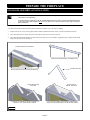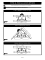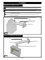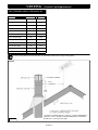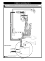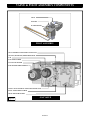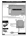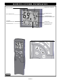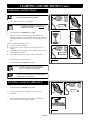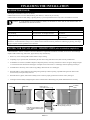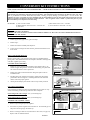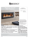
1
INSTALLATION AND OPERATING MANUAL
Intrigue Series
Direct Vent Gas Fireplaces
Models: #INT-100
#INT-200
INSTALLER: LEAVE THIS MANUAL WITH THE APPLIANCE.
CONSUMER: RETAIN THIS MANUAL FOR FUTURE REFERENCE .
This appliance may be installed in an aftermarket permanently located,
manufactured home (USA only) or mobile home where not prohibited by local
codes.
This appliance is only for use with the type of gas indicated on the rating plate.
This appliance is not convertible for use with other gases, unless a certified kit is
used.
WARNING: If the information in these instructions is not followed exactly, a
fire or explosion may result, causing property damage, personal injury or loss
of life.
—Do not store or use gasoline or other flammable vapors and liquids in the
vicinity of this or any other appliance.
WHAT TO DO IF YOU SMELL GAS:
◙ Do not light any appliance.
◙ Do not touch any electrical switch: do not use any phone in your building.
◙ Immediately call gas supplier from a neighbors phone. Follow the gas
supplier instructions.
◙ If you cannot reach your gas supplier, call the fire department.
— Installation and service must be performed by a qualified installer, service
agency or the gas supplier.
WARNING
HOT GLASS WILL CAUSE BURNS.
DO NOT TOUCH GLASS UNTIL COOLED.
NEVER ALLOW CHILDREN TO TOUCH GLASS.
Report No. 216-S-35-6.5
SEPT 2011 INT-REV-04
TABLE OF CONTENTS
TABLE OF CONTENTS
Table of Contents
VENTING (cont.)
1
SAFETY INFORMATION
Safety Information
2
COMMONWEALTH OF MASSACHUSETTS INFORMATION
Commonwealth of Massachusetts Information
3
16
Horizontal & Vertical Combination Venting Illustration
17
Termination Vent Cap Location
18
Vent Termination Clearances
19
LOG SET INSTALLATION
SPECIFICATIONS
Log Set Installation
Fireplace Dimensions
4
Clearances
4
Components List
5
Installation Overview
5
Placement Clearance Requirements
5
Stand-Off Assembly & Installation
6
Horizontal Vent Heat Shield Installation
7
Nailing Flange Assembly & Installation
7
8
Minimum Finished Opening Dimensions
8
Horizontal Terminations
9
Vertical Terminations
9
Control Board Removal
21
Control Board Installation
22
GRILL SET
Grill Set Installation
23
Grill Set Removal
23
OPERATING INSTRUCTIONS
FRAMING
Wall Enclosure Rough Opening
20
CONTROL BOARD
PREPARE THE FIREPLACE
TYPICAL INSTALLATION OPTIONS
Typical Installation Options
Restrictor Installation
10
Wiring Schematics
24
Valve and Pilot Assembly Components
25
Control Module Components
26
Remote Control Components
27
Information and Remote Control Operation
28-31
Lighting and Shutdown
32-33
Pressure Testing
34
Error Codes
35
FINALIZING THE INSTALLATION
MANTEL REQUIREMENTS
Burner Tube Adjustment / Troubleshooting
36
GLASS FRAME ASSEMBLY
Restrictor Troubleshooting / Installation after Termination Completion
37
Glass Frame Assembly Removal
11
MAINTENANCE
Glass Frame Assembly Installation
11
Maintenance
Mantel Requirements
11
TROUBLESHOOTING
GAS LINE CONNECTION
Gas Line Connection
Troubleshooting
12
39-40
CONVERSION KIT INSTRUCTIONS
LIGHT KIT COMPONENTS INSTALLATION (INT-200)
Light Kit Components Installation (INT-200)
38
Conversion Kit Instructions
12
VENTING
41-42
#INT-060 OPTIONAL UPGRADE KIT FOR INT-100
Approved Venting
13
#INT-060 Optional Upgrade Kit for INT-100
Horizontal Vent System Clearances
13
REPLACEMENT PARTS LIST
Horizontal Termination Minimum / Maximum
13
Elbows
13
Horizontal Venting Illustrations
14
Vertical Vent System Clearances
15
Restrictor
15
Horizontal / Vertical Combination Venting
15
Vertical Illustrations
16
Replacement Parts List
43-44
45
WARRANTY
Warranty
PAGE 1
46-47
SAFETY INFORMATION
This fireplace has been tested to and complies with ANSI Z21.88-2009 / CSA 2.33-2009 “VENTED GAS FIREPLACE HEATERS” and
Testing Method for Measuring Annual Effiency, CSA P.4.1-09 by OMNI-Test Laboratories, Portland, OR. Installation must conform with local
building codes or in the absence of local building codes, with the National Fuel Gas Code, ANSI Z223.1/NFPA 54 - Current Edition, or the Natural
Gas and Propane Installation Code, CSAB149.1
Installation and repair should be done only by a qualified service person. The appliance should be inspected by a
qualified service person before use. Annual inspection by a qualified service person is required to maintain warranty.
More frequent cleaning may be required due to excessive lint from carpeting, bedding materials, etc. It is imperative
that control compartments, burners and circulation air passageways of the appliance be kept clean.
If this appliance is installed directly on carpeting, tile or other combustible material other than wood flooring, the
appliance shall be installed on a metal or wood panel extending the full width and depth of the appliance.
Children and adults should be alerted to the hazards of high surface temperatures and should stay away to avoid burns
or clothing ignition.
Young children should be carefully supervised when they are in the same room as the appliance. Toddlers, young
children and others may be susceptible to accidental contact burns. A physical barrier is recommended if there are at
risk individuals in the house. To restrict access to a fireplace or stove, install an adjustable safety gate to keep toddlers,
young children and other at risk individuals out of the room and away from hot surfaces.
Clothing or other flammable material should not be placed on or near the appliance.
Adequate accessibility clearances for servicing and proper operation must be maintained.
This appliance must not share or be connected to a chimney flue serving any other appliance.
Keep area around the appliance clear of combustible materials, gasoline and other flammable vapor and liquids.
The flow of combustion and ventilation air must not be obstructed.
Due to high temperatures the appliance should be located out of traffic and away from furniture and draperies.
The glass front or any part removed for servicing the appliance must be replaced prior to operating the appliance.
Work should be done by a qualified service technician.
Clean glass only when cool and only with non-abrasive cleansers.
WARNING: DO NOT OPERATE APPLIANCE WITH THE GLASS/FRAME ASSEMBLY REMOVED, CRACKED
OR BROKEN. REPLACEMENT OF THE GLASS SHOULD ONLY BE PERFORMED BY A LICENSED OR
QUALIFIED SERVICE PERSON.
The glass assembly, Part #INT-057T, shall only be replaced as a complete unit, as supplied by Hussong Mfg. Co., Inc.
DO NOT SUBSTITUTE MATERIALS.
Do not strike or slam glass assembly.
Any safety screen or guard removed for servicing the appliance must be replaced prior to operating the appliance.
Under no circumstances should any solid fuel (wood, coal, paper or cardboard etc.) be used in this appliance.
Keep burner and control compartment clean.
Do not use this fireplace if any part has been under water. Immediately call a qualified service technician to inspect this
appliance and to replace any part of the control system and any gas control which has been under water.
PAGE 2
COMMONWEALTH OF MASSACHUSETTS REQUIREMENTS
NOTE: The following requirements reference various Massachusetts and national codes not contained in this manual.
For all sidewall horizontally vented gas fueled equipment installed in every dwelling, building or structure used in whole or in part for residential purposes,
including those owned or operated by the Commonwealth and where the side wall exhaust vent termination is less than (7) feet above finished grade in the
area of the venting, including but not limited to decks and porches, the following requirements shall be satisfied:
INSTALLATION OF CARBON MONOXIDE DETECTORS
At time of installation of side wall horizontally vented gas fueled equipment, the installing plumber or gas-fitter shall observe that a hard wired carbon monoxide detector with an alarm and battery back-up is installed on the floor level where the gas equipment is to be installed. In addition, the installing plumber
or gas-fitter shall observe that a battery operated or hard wired carbon monoxide detector is installed on each additional level of the dwelling, building or
structure served by the side wall horizontal vented gas fueled equipment. It shall be the responsibility of the property owner to secure the services of qualified
licensed professionals for the installation of hard wired carbon monoxide detectors.
In the event that the side wall horizontally vented gas fueled equipment is installed in a crawl space or attic, the hard wired carbon monoxide detector with
alarm and battery back-up may be installed on the next adjacent floor level.
In the event that the requirements of this subdivision can not be met at the time of completion of installation, the owner shall have a period of thirty (30) days
to comply with the above requirements; provided, however, that during said thirty (30) day period, a battery operated carbon monoxide detector with an
alarm shall be installed.
APPROVED CARBON MONOXIDE DETECTORS
Each carbon monoxide detector as required in accordance with the above provisions shall comply with NFPA 720 and be ANSI/UL 2034 listed and IAS
certified.
SIGNAGE
A metal or plastic identification plate shall be permanently mounted to the exterior of the building at a minimum of eight (8) feet above grade directly in line
with the exhaust vent terminal for the horizontally vented gas fueled heating appliance or equipment. The sign shall read, in print no less the one-half inch
(1/2) in size, “GAS VENT DIRECTLY BELOW. KEEP CLEAR OF ALL OBSTRUCTIONS”.
INSPECTION
The state or local gas inspector of the side wall horizontally vented gas fueled equipment shall not approve the installation unless, upon inspection, the
inspector observes carbon monoxide detectors and signage installed in accordance with the provisions of 248 CMR 5.08 (2) (a) 1 through 4.
EXEMPTIONS
The following equipment is exempt from 248 CMR 5.08 (2) (a) 1 through 4:The equipment listed in Chapter 10 entitled “Equipment Not Required To Be
Vented” in the most current edition of NFPA 54 as adopted by the Board; and Product Approved side wall horizontally vented gas fueled equipment installed
in a room or structure separate from the dwelling, building or structure used in whole or in part for residential purposes.
MANUFACTURER REQUIREMENTS - GAS EQUIPMENT VENTING SYSTEM PROVIDED
When the manufacturer of Product Approved side wall horizontally vented gas equipment provides a venting system design or venting system components
with the equipment, the instructions provided by the manufacturer for installation of the equipment and the venting system shall include:
Detailed instructions for the installation of the venting system design or the venting system components; and
A complete parts list for the venting system design or venting system.
MANUFACTURER REQUIREMENTS - GAS EQUIPMENT VENTING SYSTEM NOT PROVIDED
When the manufacturer of Product Approved side wall horizontally vented gas equipment does not provide the parts for venting the flue gases, but identifies
“special venting systems”, the following requirements shall be satisfied by the manufacturer:
The referenced “special venting systems” instructions shall be included with the appliance or equipment installation instructions and;
The “special venting systems” shall be Product Approved by the Board, and the instructions for that system shall include a parts list and detailed
installation instructions.
A copy of all installation instructions for all Product Approved side wall horizontally vented gas fueled equipment, all venting instructions, all parts lists for
venting instructions, and/or all venting design instructions shall remain with the appliance or equipment at the completion of the installation.
PAGE 3
SPECIFICATIONS
FIREPLACE DIMENSIONS
FIREPLACE
DIMENSIONS
DESCRIPTION
Height
Width
Back Width
Depth
Opening
Width
Glass Frame
Height
Stand-off
Height
Front to Vent
Center
(Vert. Term.)
Floor to Vent
Center
(Hor. Term.)
Front to
Angled Back
INCHES
34-1/2
40-7/8
30-3/8
19
35-1/2
26-5/8
10
16-1/8
32-3/8
7-7/8
MILLIMETERS
876
1038
772
483
902
676
254
410
848
200
WARNING: Top stand-off bracket must be attached to fireplace. Do not remove. Stand-off brackets are not load bearing.
Non-combustible zone: Stand-offs provide 10” (254mm) minimum clearance to header. Use only non-combustible material
in this area for entire width of fireplace. Do not use wood, sheetrock etc. in this zone. Other clearances apply. All clearances
must be maintained.
10"
254mm
44 12"
1130mm
RIGHT SIDE
34 12"
876mm
33 3 8"
848mm
FRONT
26 5 8"
676mm
4 1 4"
108mm
8 5 8"
219mm
35 12"
902mm
40 7 8"
1038mm
16 18"
410mm
30 3 8"
772mm
19"
483mm
7 7 8"
200mm
LEFT SIDE
2 1 8"
54mm
6 12"
165mm
Figure 4a
2 7 8"
73mm
CLEARANCES
Top of unit face to header (cement board may be used in this area).
10” (254mm)
From unit left & right sides and back
1/2” (13mm)
To flooring
0” (0mm)
Unit top to ceiling
31” (787mm)
Side of unit face to adjacent sidewall
3” (76mm)
Mantel 9” (229mm) deep from top of fireplace
12-1/2” (318mm)
Top of fireplace to 1” (25mm) trim
10” (254mm)
PAGE 4
SPECIFICATIONS
INT-100 COMPONENTS LIST
INT-200 COMPONENTS LIST
PART NUMBER
PART NUMBER
DESCRIPTION
DESCRIPTION
INT-600-IPI
IPI Control Board Assembly
INT-600-IPI
IPI Control Board Assembly
700-203
Manual Gas Shut-off Valve
700-203
Manual Gas Shut-off Valve
INT-135
Burner Assembly
INT-135
Burner Assembly
INT-G900
Refractory Set (back and sides)
INT-G900
Refractory Set (back and sides)
INT-500
Log Package
INT-500
Log Package
INT-057T
Glass Frame Assembly
INT-057T
Glass Frame Assembly
OCK-A5163L-I-INT-PSE
LP Conversion Kit
OCK-A5163L-I-INT-PSE
LP Conversion Kit
600-002
Double Receptacle Assembly
600-002
Double Receptacle Assembly
942-085
5” Restrictor Plate
942-085
5” Restrictor Plate
500-TRF
4 pc. Grill Assembly
500-TRF
4 pc. Grill Assembly
INT-208
Remote Control
INT-208
Remote Control
INT-RLK
Light Kit
INT-028
Fan Kit
INSTALLATION OVERVIEW
NOTE: The qualified installer should follow the procedure best suited for the installation.
1.
Frame an opening for the fireplace, allowing for vent installation (top or rear) and type of installation (corner or flat wall application).
2.
If masonry (optional) is used, prepare foundation for the masonry load. A lintel is required to support the added weight above fireplace.
3.
Attach nailing flanges to fireplace.
4.
Insert fireplace into framing.
5.
Install hearth (if applicable).
6.
Complete electrical hook-up. Install any standard or optional electrical components at this time.
7.
Complete gas line installation.
8.
Complete venting installation.
9.
Secure fireplace to flooring through holes in outer box bottom and to framing with nailing flanges. Verify all clearances at this point.
10. Install facing material, mantel or cabinetry, allowing room for optional full face doors, if applicable.
11. Install logs.
12. Install grills and optional decorative doors / faces.
13. Verify proper operation of fireplace and all components.
PLACEMENT CLEARANCE REQUIREMENTS
This fireplace must be installed on a level surface capable of supporting the fireplace and venting.
Fireplace must be placed directly on wood or non-combustible surface (not linoleum or carpet) extending entire depth and width of
fireplace.
Due to high surface temperatures, fireplace should be located out of traffic and away from furniture and draperies.
This fireplace may be installed in a bedroom.
Please be aware of the large amount of heat this fireplace will produce when determining a location.
PAGE 5
PREPARE THE FIREPLACE
STAND-OFF ASSEMBLY & INSTALLATION
WARNING: Top stand-off brackets and stand-off heat shields must be attached to fireplace. Do not remove.
These items are not load bearing.
Non-combustible zone: Stand-offs provide 10” (254mm) minimum clearance to header. Use only non-combustible material
in this area for entire width of fireplace. Do not use wood, sheetrock etc. in this zone. Other clearances apply. All clearances
must be maintained.
Top stand-off brackets and stand-off heat shields are attached to fireplace top in a flat state for shipping.
1.
Remove and save (4) screws securing stand-off heat shields and stand-off brackets, and (4) screws located under these items.
2.
Form stand-off brackets as shown and re-attach to fireplace using screws previously removed.
3.
Form stand-off heat shields and attach to stand-off brackets using (8) screws provided in components packet. (Stand-off heat shield
flanges face up and to front of fireplace).
STAND-OFF BRACKETS AS SHIPPED
FORM STAND-OFF BY BENDING AT PERFORATIONS
FORMED STAND-OFF
REMOVE SCREWS SECURING STAND-OFF BRACKETS
STAND-OFF BRACKETS
INSTALLED
ALIGN HOLES IN FORMED STAND-OFFS WITH HOLES IN
FIREPLACE TOP. SECURE WITH (4) SCREWS.
STAND-OFF HEAT
SHIELDS INSTALLED
ALIGN HOLES IN FORMED STAND-OFF HEAT SHIELDS WITH
HOLES IN STAND-OFF BRACKETS. SECURE WITH (8) SCREWS.
Figure 6a
PAGE 6
PREPARE THE FIREPLACE
HORIZONTAL VENT HEAT SHIELD INSTALLATION
IMPORTANT: The horizontal vent heat shield must be installed when using a 45-degree elbow to horizontally position the vent system.
EXCEPTION: Corner installations
1.
Loosen, but do not remove center three screws at back of fireplace as shown.
2.
Bend horizontal heat shield at perforation to a 45° angle. Slide (3) slots on
horizontal vent heat shield under loosened screws. Re-tighten screws.
Attach here.
Figure 7a
NAILING FLANGE ASSEMBLY & INSTALLATION
1.
Remove (4) nailing flanges from fireplace sides.
2.
With the 1/2” (13mm) stand-offs on nailing flanges facing away from fireplace, align nailing flange with holes on outside corners of
fireplace. Secure with screws through slots in nailing flanges (additional screws provided in components packet).
3.
Bend perforation on nailing flange until parallel with fireplace face. Do not bend toward fireplace face.
4.
Position framing stud against 1/2” (13mm) stand-off (located on backside of nailing flange). Secure with nails or screws.
NOTE: Depending on facing material, tabs can be adjusted forward or back up to 1/2” (13mm).
CAUTION: NEVER PERMANENTLY REMOVE THESE ASSEMBLIES FROM FIREPLACE - THEY MUST BE SECURED IN PLACE REGARDLESS OF
FINISH MATERIAL USED.
When installed, nailing flanges provide minimum 1/2” (13mm) clearance from fireplace sides.
FRONT VIEW
1/2” (13mm)
CLEARANCE
STAND-OFF
NAILING FLANGE
AS SHIPPED
FRAMING STUD
NAILING FLANGES
INSTALLED
TOP VIEW
1/2” (13mm)
CLEARANCE
STAND-OFF
FRAMING STUD
NAILING FLANGE
Figure 7a
PAGE 7
FRAMING
WALL ENCLOSURE ROUGH OPENING
IMPORTANT: Framing dimensions should allow for wall covering thickness and fireplace facing materials. If using a hearth, adjust
rough opening size as necessary to maintain at least minimum clearance requirements.
IMPORTANT: Non-combustible facing material may be applied over (but not directly to) fireplace face. This will prevent facing material
from falling off due to heat expansion. Do not obstruct the flow of ventilation air.
MINIMUM FINISHED OPENING DIMENSIONS
HORIZONTAL TERMINATION: 44-1/2”(1130mm) High x 41-3/8”(1051mm) Wide x 21-1/2” (546mm) Deep.
1/2” (13mm) clearance at back and sides of fireplace must be maintained.
VERTICAL TERMINATION: 44-1/2”(1130mm) High x 41-3/8”(1051mm) Wide x 21-1/2” (546mm) Deep.
1/2” (13mm) clearance at back and sides of fireplace must be maintained.
NOTE: Provide adequate clearance in front of fireplace to operate lower grill, open and close optional full door face doors, access
components, installation of gas line, fan, etc. See Figure 8b.
WARNING: Provide adequate clearances around air openings into the combustion chamber.
Do not obstruct upper and lower grill openings. Room air enters through lower passage, is heated and exits through upper passage.
Blocking these passages may result is overheating, creating a potentially hazardous situation.
Refer to vent manufacturer installation instructions to determine
vent framing dimensions.
OPTIONAL FULL DOOR FACE DIMENSIONS
If installing an optional full door face, please refer below for full
face dimensions before applying facing material.
NOTE: Consider height of hearth finish material (stone, brick,
marble etc.) when building fireplace platform. Bottom
of fireplace must be level with finished hearth to allow
for lower grill operation and proper fit of optional
decorative full door faces.
NOTE: 1/2” (13mm) side overlap applies to both sides of face.
Illustrations show True Dimensions. We recommend
1/4” (6mm) clearance on all sides to allow for uneven
finish material.
41-3/4”
(1060mm)
44-1/2”
(1130mm)
41-3/8”
(1051mm
36-5/32”
(918mm)
Hearth
Height
Minimum:
21-1/2”(546mm)
Figure 8a
Figure 8b
PAGE 8
FRAMING
Determine exact position of your fireplace, including hearth height, width, and depth, (if applicable). If possible, place fireplace in such a
manner that vent termination will be placed between two studs, eliminating the need for additional framing.
If masonry is to be used (optional), prepare the necessary foundation for the masonry load. When masonry construction is used, a lintel
must be used over top of fireplace to support the added weight.
Build hearth to desired size and height. If a hearth extension is desired, combustible material may be used.
NOTE: Consider height of hearth finish material (stone, brick, etc.) when building fireplace platform. Bottom of fireplace must be level
with finished hearth to allow for lower grill operation and proper fit of optional decorative full door faces.
WARNING: Install fireplace on hard metal or wood surface extending the full width and depth of fireplace.
Minimum platform size: 40-7/8” (1038mm) wide x 19” (483mm) deep.
FIRE HAZARD: Do NOT install directly on carpeting, vinyl, or any combustible material other than wood.
IMPORTANT: Vent cap location must be in compliance with guidelines on page #18 of this manual.
HORIZONTAL TERMINATIONS
Follow vent pipe manufacturer‟s installation instructions for horizontal
terminations. Include required vent manufacturer‟s wall pass-thru clearances
when determining framing dimensions.
MINIMUM HORIZONTAL FRAMING DIMENSIONS
VENT PIPE CENTER (A)
FRAMED OPENING TOP (B)
RIGID PIPE
33-3/8” (848mm)
Per vent manufacturer requirements
FLEX PIPE
36-7/8” (937mm)
Per vent manufacturer requirements
VERTICAL TERMINATIONS
Follow vent pipe manufacturer‟s installation instructions for vertical
terminations. A minimum 1” (25mm) clearance on all sides of vertical
vent pipe must be maintained.
NOTE: The included Horizontal Vent Heat Shield is not used for
vertical configurations.
Figure 9a
CAUTION: Cold air transfer area. The surrounding fireplace chase must comply with all clearances as outlined in this manual and be
constructed in compliance with local building codes. Outside walls should be insulated to prevent cold air from entering room.
CAUTION: Due to high temperatures, this fireplace should be located out of traffic areas and away from furniture and draperies.
PAGE 9
TYPICAL INSTALLATION OPTIONS
IMPORTANT: The horizontal heat shield included with this fireplace must be installed when using a 45-degree elbow directly off top
of unit to horizontally position vent system. EXCEPTION: Corner installations.
NOTE: HORIZONTAL VENT HEAT SHIELD NOT SHOWN FOR CLARITY PURPOSES ONLY.
TYPICAL HORIZONTAL INSTALLATION
1
2"
13mm
1
19 MINIMUM:
2"
495mm
21 ½” (546mm)
41 3 8"
1051mm
Figure 10a
TYPICAL CORNER INSTALLATION
34 7 8"
886mm
49 1 4"
1251mm
1
2"
13mm
1
2"
13mm
69 3 4"
1772mm
Figure 10b
TYPICAL VERTICAL INSTALLATION
2"
51mm
1"
25mm
MINIMUM:
21"
21 ½” (546mm)
533mm
Figure 10c
41 3 8"
1051mm
PAGE 10
MANTEL REQUIREMENTS
WARNING: TOP STAND-OFF BRACKETS MUST BE ASSEMBLED AND ATTACHED TO FIREPLACE. DO NOT REMOVE.
STAND-OFF BRACKETS ARE NOT LOAD BEARING.
NON-COMBUSTIBLE ZONE:
Rigid pipe: 1” (25mm) above elbow for entire width and depth (behind header) of fireplace.
Flexible venting: 1” (25mm) above elbow for entire width and depth (behind header) of fireplace.
16 12"
419mm
14 12"
368mm
13" (330mm)
11" (279mm)
9" (229mm)
1
12 2"
318mm
NON-COMBUSTIBLE ZONE:
No materials allowed on top of fireplace within shaded
area for the entire width and depth of fireplace. This
air space must remain open.
13 12"
343mm
1"
25mm
NON-COMBUSTIBLE MATERIAL ONLY
10"
254mm
HORIZONTAL VENT HEAT
SIDE VIEW
Figure 11a
GLASS FRAME ASSEMBLY
CAUTION: TO PREVENT GLASS FRAME ASSEMBLY FROM FALLING FROM FIREPLACE AND BECOMING DAMAGED, FOLLOW THESE
INSTRUCTIONS EXACTLY WHEN REMOVING AND INSTALLING GLASS FRAME ASSEMBLY.
REMOVE GLASS FRAME ASSEMBLY
1.
Locate spring-loaded handles securing glass frame assembly at top & bottom of firebox.
2.
Pull bottom handles out and down to release glass frame assembly bottom.
3.
Pull top handles out and up to release glass frame assembly top.
INSTALL GLASS FRAME ASSEMBLY
1.
Making sure wide lip of glass frame assembly is at bottom and narrow lip at top, place assembly onto fireplace front.
2.
Pull top handles out and down to secure glass frame assembly top.
3.
Pull bottom handles out and up to secure glass frame assembly bottom.
Narrow lip at top of glass frame assembly.
Pull latches out and up to release glass frame assembly top.
Pull latches out and down to attach glass frame assembly top.
Pull latches out and down to release glass frame assembly bottom.
Pull latches out and up to attach glass frame assembly bottom.
Figure 11b
Wide lip at bottom of glass frame assembly.
PAGE 11
GAS LINE CONNECTION
GAS CONVERSION
This fireplace is manufactured for use with Natural Gas. An LP conversion kit, is included with this fireplace. Follow instructions included
with conversion kit if converting to LP gas.
ATTENTION: The conversion shall be carried out in accordance with the requirements of US or Canadian authorities having local
jurisdiction and in accordance with the requirements of the ANSI Z223.1 installation code.
CAUTION: Installation of the gas line must only be done by a qualified person in accordance with local building codes, if any.
If not, follow ANSI 223.1.
Commonwealth of Massachusetts: Installation must be done by a licensed plumber or gas fitter.
NOTE: A listed (and Commonwealth of Massachusetts approved) 12” (13mm) T- handle manual shut-off valve and flexible gas
connector (included) are connected to the 1/2” (13mm) control valve inlet. If substituting for these components, please
consult local codes for compliance.
NOTE: This fireplace is equipped with a 3/8”(10mm) x 18” (457mm) long flexible gas connector and manual shut-off valve. The
gas line should be run to the point of connection where the shut-off valve and flexible gas line will connect.
NOTE: The appliance and its individual shutoff valve must be disconnected from the gas supply piping system during any pressure
testing of that system at pressures in excess of ½ psi. (3.5 kPa).
NOTE: The appliance must be isolated from the gas supply piping system by closing its individual manual shut-off valve during
any pressure testing of the gas line at test pressures equal to or less than ½ psi (3.5 kPa).
NOTE: For high altitude installations, consult the local gas distributor or the authority having jurisdiction for proper rating
methods.
IMPORTANT: The efficiency rating of this appliance is a product of thermal efficiency rating determined under continuous operating
conditions and was determined independently of any installed system.
MINIMUM INLET GAS PRESSURE
NATURAL GAS
LP GAS
5” WC (1.25 kPa) (7” WC (1.74 kPa) recommended)
11” WC (2.74 kPa) (recommended)
MAXIMUM INLET GAS PRESSURE 10.5” WC (2.62 kPa)
13” WC (3.24 kPa)
MANIFOLD PRESSURE (HI)
3.5 (.87 kPa)
10 (2.49 kPa)
MANIFOLD PRESSURE (LO)
.90 (.22 kPa)
2.9 (.72 kPa)
ORIFICE SIZE
#57 & #37
#63 & #51
INPUT BTU/hr. (kW)
39,500 (11.58 kW)
39,500 (11.58 kW)
MINIMUM INPUT BTU/hr. (kW)
18,500 (5.42 kW)
18,500 (5.42 kW)
LIGHT KIT COMPONENT INSTALLATION (INT-200 only)
CAUTION: Disconnect all electrical power from fireplace before performing this task
NOTE: To avoid damage and prolong the life of halogen bulbs, never touch with bare hands. Always use a soft cloth when handling.
1.
Install halogen bulbs (included in components
packet) into lamp bases.
2.
Place amber light filters into light cylinders.
PAGE 12
VENTING
IMPORTANT: Consult the local and national installation codes to assure adequate combustion and ventilation air is available.
IMPORTANT: Flame height and appearance will vary depending upon venting configuration and type of fuel used.
Venting requirements apply to both Natural and LP gas.
Refer to the vent systems manufacturer's installation manual for complete installation instructions.
Installation must conform with the venting requirements and restrictions as outlined in this manual.
Provide a means for visually checking vent connection to fireplace after fireplace is installed.
APPROVED VENTING
Simpson Dura-Vent DV-GS 5” x 8” and 4” x 6-5/8” -with reducer (horizontal and vertical terminations).
Metal Fab Direct Chimney System 5” x 8” (horizontal and vertical terminations).
ICC Direct Chimney Systems 5” x 8” (horizontal and vertical terminations).
Selkirk-Metalbestos Chimney Systems 5” x 8” and 4” x 6-5/8” -with reducer (horizontal and vertical terminations).
BDM 5” x 8” Chimney Systems (horizontal and vertical terminations).
Security 5” x 8” Chimney Systems (horizontal and vertical terminations).
Ameri-Vent 5” x 8” Chimney Systems (horizontal and vertical terminations).
HORIZONTAL VENT SYSTEM CLEARANCES
ALL APPROVED VENTING
TOP
BOTTOM
SIDES
1 inches (25mm)
1 inch (25mm)
1 inch (25mm)
VERTICAL VENT SYSTEM CLEARANCES
ALL APPROVED VENTING
TOP
BOTTOM
SIDES
1 inch (25mm)
1 inch (25mm)
1 inch (25mm)
HORIZONTAL TERMINATIONS
MINIMUM: 45° elbow + 6” (152mm) horizontal + termination cap.
MAXIMUM: 45° elbow + 6ft. (1.83m) + termination cap.
HORIZONTAL TERMINATIONS
(with reducer)
NAT GAS MINIMUM: 2ft (610mm) vertical + reducer + 90° elbow + 6” (152mm) horizontal + termination cap.
NAT GAS MAXIMUM: 2ft. (610mm)vertical + reducer + 90° elbow + 12ft. (3.66m) + termination cap.
LP GAS MINIMUM: 2ft. (610mm)vertical + reducer + 90° elbow + 6” (152mm) + termination cap.
LP GAS MAXIMUM: 2ft. (610mm) vertical + reducer + 90° elbow + 2ft. (610mm) + termination cap.
LP GAS MAXIMUM: 3ft. (914mm) vertical + reducer + 90° elbow + 12ft. (3.66m) + termination cap.
IMPORTANT: Wall pass-thru required for all horizontal runs. Refer to vent manufacturer to determine which pass-thru will work best for
your application and wall thickness.
IMPORTANT: The horizontal vent heat shield must be installed when using a 45-degree elbow to horizontally position the vent system.
Exception: corner installations.
ELBOWS
The following statement applies to horizontal, vertical, or a combination of horizontal/vertical elbows:
For each additional 90° elbow used after first elbow, 3ft. (914mm) must be subtracted from maximum allowed venting. For each 45° elbow
used, 1-1/2ft. (457mm) must be subtracted from maximum venting allowed.
NOTE: (2) 45° degree elbows may be used in place of (1) 90° elbow.
PAGE 13
VENTING
HORIZONTAL TERMINATIONS
NOTE: Horizontal sections require 1/4” (6mm) rise for every 12” (305mm) of travel.
NOTE: Page 16 has information on restrictor installation in conjunction with venting installation. Page 37 has information on restrictor
recommendations depending on burner flame appearance and instructions on installation after venting is completed.
CAUTION: This gas appliance must not be connected to or joined with any other chimney flue serving another appliance.
IMPORTANT: Wall pass-thru required for all horizontal runs. Refer to vent manufacturer to determine which pass-thru will work best
for your application and wall thickness.
IMPORTANT: The horizontal vent heat shield must be installed when using a 45-degree elbow to horizontally position vent system.
Exception: corner installations.
Horizontal Vent Heat Shield
45° Elbow
Minimum: 6in. (152mm)
Maximum: 6ft. (1.83m)
Termination Cap
Figure 14a
TYPICAL CORNER INSTALLATION
Pipe
Termination Cap
90° Elbow
45° Elbow
Figure 14b
PAGE 14
VENTING
VERTICAL VENT SYSTEM CLEARANCES
ALL APPROVED VENTING
TOP
BOTTOM
SIDES
1 inch (25mm)
1 inch (25mm)
1 inch (25mm)
VERTICAL TERMINATIONS
MINIMUM: 45˚ elbow + 2ft. (610mm) + termination cap.
MAXIMUM: 45˚ elbow + 50ft. (15.2m) + termination cap.
MAXIMUM (if using reducer): 45° elbow + 2ft. (610mm) + reducer + 48ft. (14.63m) + termination cap.
HORIZONTAL & VERTICAL COMBINATION TERMINATIONS
MAXIMUM: 18ft. (5.49m) horizontal + 18ft. (5.49m) vertical + cap. [36ft. (10.98m) total].
MAXIMUM (with reducer): 45° elbow + 2ft. (610mm) + reducer + 16ft. (4.88m) hor. /vert + 18ft. (5.49m) hor / vert + term. cap.
ATTENTION: IF INSTALLING WITH RIGID-TO-FLEX PIPE SYSTEMS:
More than a 30 degree bend constitutes a 45 degree elbow.
More than a 45 degree bend constitutes a 90 degree elbow.
More than a 90 degree bend is not permissible.
IMPORTANT: Wall pass-thru required for all horizontal runs. Refer to vent manufacturer to determine which pass-thru will work best for
your application and wall thickness.
IMPORTANT: The horizontal vent heat shield must be installed when using a 45-degree elbow to horizontally position the vent system.
Exception: corner installations.
ELBOWS
The following statement applies to horizontal, vertical, or a combination of horizontal/vertical elbows:
For each additional 90° elbow used after first elbow, 3ft. (914mm) must be subtracted from maximum allowed venting. For each 45° elbow
used, 1-1/2ft. (457mm) must be subtracted from maximum venting allowed.
NOTE: (2) 45° degree elbows may be used in place of (1) 90° elbow.
IMPORTANT: The horizontal vent heat shield must be installed when using a 45-degree elbow to horizontally position the vent system.
Exception: corner installations
RESTRICTOR
We recommend installing a restrictor if using straight vertical terminations. It is important to remember each installation is unique and
affected by various factors including venting configuration, altitude and climate. Therefore, after fireplace installation is complete, restrictor
modification may be necessary.
A restrictor is included in fireplace components packet.
Please refer to page 16 for installation instructions if installing the restrictor in conjunction with venting.
Page 37 has information on restrictor recommendations depending on burner flame appearance and instructions on installation after venting
is completed.
PAGE 15
VENTING
VERTICAL TERMINATIONS
CAUTION: This gas appliance must not be connected to or joined with any other chimney flue serving another appliance.
Termination Cap
Minimum: 2ft. (610mm)
Maximum: 50ft. (15.2m)
45° Elbow
Figure 16a
RESTRICTOR INSTALLATION
TO BE USED AT INSTALLER DISCRETION.
Large Restrictor
Remove tab (s) to
create small restrictor
Bend tabs to approx. 80 degree
angles to create tension to hold
itself in place when installed.
Slide restrictor into exhaust pipe on top of fireplace with
tabs pointing towards you prior to attaching venting.
Figure 16b
NOTE: Page 37 has information on restrictor recommendations depending on burner flame appearance and instructions on installation
after venting is completed.
PAGE 16
VENTING
(9.14m)
(6.1m)
HORIZONTAL / VERTICAL COMBINATION
0 2 4 6 8 10 12 14 16 18 20 22 24 26 28 30
52
(15.2m) 50
48
46
44
42
(12.9m) 40
38
36
34
32
30
28
26
24
22
(6.1m) 20
18
16
14
12
10
8
6
4
2
(ft.) 0
Termination must be
within shaded area
HORIZONTAL / VERTICAL COMBINATION:
(5.49m) 18' Vertical
(5.49m) 18' Horizontal
Figure 17a
ATTENTION: IF INSTALLING WITH RIGID-TO-FLEX PIPE SYSTEMS:
More than a 30 degree bend constitutes a 45 degree elbow.
More than a 45 degree bend constitutes a 90 degree elbow.
More than a 90 degree elbow is not permissible.
CAUTION: This gas appliance must not be connected to or joined with any other chimney flue serving another appliance.
NOTE: Page 16 has information on restrictor installation in conjunction with venting installation.
Page 37 has information on restrictor recommendations depending on burner flame appearance and instructions on
installation after venting is completed.
Horizontal sections require 1/4” (6mm) rise for every 12” (305mm) of travel.
The following statement applies to horizontal, vertical, or a combination of horizontal / vertical elbows:
For each additional elbow used after first elbow, 3ft. (914mm) must be subtracted from maximum venting allowed.
For each 45° elbow used, 1-1/2ft. (457mm) must be subtracted from maximum venting allowed.
(2) 45° degree elbows may be used in place of (1) 90° elbow.
IMPORTANT: Wall pass-thru required for all horizontal runs. Refer to vent manufacturer to determine which pass-thru will work best for
your application and wall thickness.
IMPORTANT: The horizontal vent heat shield must be installed when using a 45-degree elbow to horizontally position the vent system.
Exception: corner installations.
PAGE 17
TERMINATION VENT CAP LOCATION
This gas appliance must not be connected to a chimney serving any other appliance.
1.
2.
Terminations against vinyl siding must use a vinyl siding protector. Follow instructions included.
DO NOT RECESS TERMINATION KIT INTO OUTSIDE BUILDING MATERIALS - i.e.: brick, stone, siding, etc. If necessary,
extend framing so that termination kit will be exposed once building materials are installed.
Vent termination must not be located where it will become plugged by snow or other material. The flow of combustion and ventilation
air must be not obstructed.
3.
LOCATION CLEARANCES
A. Above grade, veranda, porch, deck, balcony - 12" (305mm).
B. Operable window or door - CANADA: 12" (305mm). US: 9” (229mm).
C. Permanently closed window* - 12" (305mm) (recommended to prevent condensation on window).
D. Ventilated soffit* - 24" (610mm).
E. Unventilated soffit* - 12" (305mm).
F. Outside corner* - 3" (76mm).
G. Inside corner* - 10” (254mm).
H. Meter / Regulator: CANADA: Not to be installed above a gas meter/regulator assembly within 3ft. (914mm) horizontally from the
centerline of the regulator within a height of 15ft. (4.57m). US*.
I. Gas Service regulator vent outlet : CANADA: 3ft. (914mm). US*.
J. Non-mechanical air supply inlet to building or the combustion air inlet to any other appliance. CANADA: 12" (305mm).
US: 9” (229mm).
K. Mechanical air supply inlet. CANADA: 6ft. (1.83m) US: 3ft. (914mm) above if within 10ft. (3.05m) horizontally.
Massachusetts installations: 10ft. (3.05m).
L. Above paved side-walk or paved driveway located on public property - 7ft. (2.13m). US*
NOTE: A vent cannot be located directly above a side-walk or paved driveway that is located between two single family dwellings and
serves both dwellings.
M.
N.
O.
P.
Under veranda, porch, deck, or balcony (must be fully opened on a minimum of 2 sides) - 12" (305mm).
Between two horizontal terminations - 12" (305mm).
Between two vertical terminations - 12" (305mm). Terminations may be same height.
Above furnace exhaust or inlet - 12" (305mm).
*Clearance must be in accordance with local installation codes & the requirements of the gas supplier.
Denotes where installation not allowed
Figure 26a
Figure
18a
PAGE 18
VENTING
(Vertical Cap Requirements)
VENT TERMINATION CLEARANCES
Roof Pitch
H (Min.) Ft.
H (Min.) m
Flat to 6/12
1.0
0.30
Over 6/12 to 7/12
1.25
0.38
Over 7/12 to 8/12
1.5
0.46
Over 8/12 to 9/12
2.0
0.61
Over 9/12 to 10/12
2.5
0.76
Over 10/12 to 11/12
3.25
0.99
Over 11/12 to 12/12
4.0
1.22
Over 12/12 to 14/12
5.0
1.52
Over 14/12 to 16/12
6.0
1.83
Over 16/12 to 18/12
7.0
2.13
Over 18/12 to 20/12
7.5
2.27
Over 20/12 to 21/12
8.0
2.44
CAUTION: This appliance must not be connected to or joined with any chimney flue serving any other appliance.
1ft.*
(305mm)
Figure 19a
* IF VENT IS CLOSER THAN 1ft. (305mm), IT MUST TERMINATE AT
LEAST 2ft. (0.61m) HIGHER THAN ANY PORTION OF A BUILDING
WITHIN 10ft. (3.05m) OF THE VENT.
PAGE 19
#INT-500 LOG SET INSTALLATION
ATTENTION: If converting to LP (propane) gas or installing optional fan / light kit do so now before installing log set.
Follow instructions included with kits.
NOTE: Log numbers are located on the bottom of each log. Refer to following instructions and illustrations for proper placement.
CAUTION: Do not place logs directly over burner port holes.
Improper log placement may affect flame appearance and cause excessive soot to build up on logs and glass.
#4
#1
#3
#2
#4
Figure 20a
Align holes in bottom of logs #1, #2 & #3 with mounting pins on burner cover, setting down into position.
Position #4 logs (2) as shown above. Do not allow logs to block burner ports.
#5
#6
#7
#9
#8
#10
Figure 20b
Install #5 - #10 logs as shown above, aligning with notches in base logs,
and in the case of log #7, aligning notch in log with burner grate.
Install #11 - #12 logs as shown below, aligning with notches in lower logs.
#11
#12
Figure 20c
Randomly place “klinkers” in this area. Do not place klinkers directly on burner ports.
Use a steel or stiff bristle brush to distribute Rock Wool Embers onto logs and burner.
PAGE 20
CONTROL BOARD REMOVAL
CAUTION: If burner and/or pilot have been burning, use appropriate protection to avoid burns or damage to personal property before
removing any components.
WARNING: DO NOT OPERATE THIS FIREPLACE WITHOUT SEALING GASKET (LOCATED UNDER CONTROL BOARD) IN PLACE.
IF GASKETING IS DAMAGED, IT MUST BE REPLACED.
1.
Use remote to turn fireplace off.
2.
Shut off gas supply at manual shut-off valve. Disconnect gas line flex
tube from the manual shut-off valve.
3.
Unplug all components from electrical outlet, disconnect all wiring
harnesses attached to gas valve, disconnect pilot assembly orange and
white leads from main control module.
4.
INT-200 only: Disconnect light kit communication link (black and
white leads) from extension module communication link (red and white
leads).
Back
Burner
5.
Remove upper hood, upper louver, glass assembly, and logs.
Front
Burner
6.
Remove back burner; secured with screws, (2) at front, (2) at back.
7.
INT-200 only: Remove light kit cylinders, amber light filters, and
halogen bulbs. Remove screws securing light stands, lay light stands on
control board.
8.
Remove side refractory panels.
9.
Loosen front orifice bracket screws, push orifice backwards far enough
to release from venturi.
10. Remove front burner, secured with screws, (2) at front, (2) at back.
11. Remove (8) screws securing control board. Lift board up and out of
firebox.
Back
Burner
Front
Burner
Light Stands
(INT-200 only)
Back Orifice
Orifice Bracket
Front Orifice
Bracket Screws
Figure 21a
PAGE 21
CONTROL BOARD INSTALLATION
WARNING: DO NOT OPERATE THIS FIREPLACE WITHOUT SEALING GASKET (LOCATED UNDER CONTROL BOARD) IN PLACE.
IF GASKETING IS DAMAGED, IT MUST BE REPLACED.
1.
Place control board in firebox, aligning holes in board to holes in
firebox bottom. MAKE SURE SEALING GASKET IS IN PLACE ON
FIREBOX BOTTOM! Secure with screws previously removed.
2.
Reinstall front burner. Align front burner orifice with front venturi, pull
orifice bracket forward until orifice is seated inside venturi. Tighten
orifice bracket screws. Figure 22a. Secure burner with (4) screws
previously removed.
3.
Reinstall side refractory panels.
4.
INT-200 only: Reinstall light kit stands (secure with screws previously
removed), halogen bulbs, cylinders and amber light filters.
5.
Reinstall back burner assembly, making sure venturi is properly
positioned over back burner orifice. Figure 22a. Secure with 4 screws
previously removed.
6.
Reinstall log set.
7.
Reconnect gas line to manual shutoff valve.
8.
Reconnect all wiring harnesses to gas valve, reconnect pilot assembly
orange and white leads to main control module. Plug all components
into electrical outlet.
9.
Light Stands
(INT-200 only)
Back Orifice
Orifice Bracket
Front Orifice
INT-200 only: Reconnect light kit communication link (black and
white leads) to extension module communication link (red and white).
(Black to red, white to white).
Bracket Screws
10. Reinstall glass frame assembly, upper hood and upper louver.
11. Turn gas on.
Back
Burner
12. Verify proper log placement, operation of fireplace, and any electrical
components.
Front
Burner
Back
Burner
Front
Burner
Front
Back
Proper burner venturi placement over burner orifices (cut-away side view)
Figure 22a
Figure 22b
PAGE 22
GRILL SET
INSTALLATION
1
1.
Align hooks in upper louver to slots located in fireplace face.
Set down into position.
2.
Insert upper hood flange into clips located at top of upper air
passage, keeping in mind this is a fairly tight fit.
3.
Partially thread (2) screws (included in components packet)
into nuts at each end of lower grill. Secure to fireplace by
threading screws into corresponding holes in inside flange of
lower grill opening. The lower grill can now be opened and
closed to access gas valve and controls.
2
Slide flange on upper hood into
clips at top of upper air passage
REMOVAL
1.
Use both hands to pull hood out of upper air passage clips.
2.
Lift upper louver up and out of slots.
3.
Remove screws securing lower grill at each end to remove
from fireplace.
Upper hood clips
3
Thread screws into nuts grill ends and secure to lower grill opening.
Figure 23a
PAGE 23
WIRING SCHEMATICS
IMPORTANT: THIS SYSTEM REQUIRES ELECTRICITY (120 V) AND / OR BATTERIES TO OPERATE. USING BATTERY BACK UP WILL
OPERATE BURNER ONLY. FAN AND LIGHT COMPONENTS WILL NOT FUNCTION ON BATTERY BACK-UP POWER.
(WHITE)
(RED)
Included with INT-200 only
Figure 24a
THIS SYSTEM IS GROUND
TO FIREBOX CHASSIS.
PAGE 24
VALVE & PILOT ASSEMBLY COMPONENTS
PILOT
IGNITER
FLAME SENSOR
PILOT ASSEMBLY
PILOT INTERNAL SOLENOID CONNECTION
OUTLET (MANIFOLD) PRESSURE SCREW
CAP
LOW LIMIT SCREW
VALVE STEP MOTOR
STEP MOTOR WIRE HARNESS
MAIN VALVE INTERNAL SOLENOID CONNECTION
PILOT ADJUSTMENT SCREW
INLET PRESSURE SCREW
Figure 25a
GAS VALVE
PAGE 25
CONTROL MODULE COMPONENTS
LEARN BUTTON
VALVE STEP MOTOR TERMINAL
COMMUNICATION LINK TO
EXTENSION MODULE
AC ADAPTOR CONNECTION
MAIN CONTROL MODULE
CONTINUOUS PILOT ON/OFF SWITCH
REMOTE ON/OFF SWITCH
„S‟ SENSOR PILOT CONNECTION
„I‟ IGNITER PILOT CONNECTION
NON-OPERATIONAL
BACK-UP
BATTERY PACK
COMMUNICATION LINK
TO LIGHT KIT
COMMUNICATION LINK
TO CONTROL MODULE
AC ADAPTOR
FAN CORD PLUG-IN
EXTENSION MODULE
#INT-200 only
Figure 26a
PAGE 26
REMOTE CONTROL INFORMATION
THERMOSTAT MODE ICON
MANUAL ON / OFF
BATTERY LIFE ICON
ROOM TEMPERATURE
SET TEMPERATURE
(visible only in THERMO MODE)
FAN SPEED
Operational with INT-200
LIGHT LEVEL
Operational with INT-200
CONTINUOUS PILOT
CHILD PROOF ICON
FLAME HEIGHT
Figure 27a
PAGE 27
IPI INFORMATION
ELECTRICAL WARNING AND INFORMATION:
Electrical wiring must be installed by a licensed electrician.
Do NOT wire 120V to wall switch.
Uninterrupted or continuous power is required at all times in IPI systems EXCEPT when using battery back-up.
Incorrect wiring will override IPI safety lockout and may cause an explosion.
Disconnect 120V before servicing
A duplex receptacle and box cover are supplied in fireplace components packet to be used when hardwiring to electrical box located under
firebox on right side of fireplace. Ensure duplex box cover is installed with flange to top.
ATTENTION: THIS SYSTEM GOES THROUGH A CALIBRATION MODE WHEN SWITCHING FROM ON TO THERMO TO
OFF MODES, CREATING A HUMMING SOUND WHICH IS A NORMAL PART OF OPERATION.
CONTINUOUS PILOT
(FOR VERY COLD CONDITIONS)
The IPI gas control system has the option of a continuous (standing) pilot feature. This allows you to change from a spark-to-pilot
system to a standing pilot system during cold weather conditions. By having the pilot on continuously, the firebox will remain warm
and a draft is established in the vent, allowing the main burner to turn on with less air-flow disruption.
When continuous pilot mode is activated and fireplace is turned ON, the pilot will spark and light. When fireplace is turned OFF, the
pilot will remain lit when main burner has been turned OFF.
This pilot feature can be activated or de-activated by the hand held remote control transmitter. Instructions on following page.
OPERATION USING BATTERY POWER
This fireplace has an optional battery operation if electrical power is lost. Position battery pack with four “AA” size batteries installed
between valve and front of fireplace. This is the coolest location under firebox, ensuring longer battery life.
NOTE: When operating fireplace in this capacity, the only function available is flame modulation.
MATCHING SECURITY CODES
Before matching security codes make sure 120V AC is connected and powered
to fireplace, and hand held remote control is installed with (2) AA batteries.
LEARN BUTTON
It may be necessary to program main control module to LEARN the security
code of the hand held remote control upon initial use, if batteries are replaced, or
if a replacement remote control is purchased from your dealer.
1.
When matching security codes, be sure slide button on main control module
is in REMOTE; the code will not “LEARN” if slide is in OFF.
2.
Program main control module to LEARN a new security code by pushing in
LEARN button on main control module for 2 seconds, then releasing. (You
should then hear a single „beep‟ letting you know module is ready to learn a
new code).
3.
Press MODE button on hand held remote control (you should hear four
„beeps‟ in rapid succession in main control module, indicating remote
control‟s code has been programmed into the main control module). When
an existing main control module is introduced to a new hand held remote
control, the new security code will overwrite the old one.
If it ever becomes necessary to clear the memory from the hand held remote
control, simply push and hold the LEARN button for 10 seconds (you should
hear three long beeps in succession). You may now follow steps outlined above
to „RE-LEARN‟ security codes.
PAGE 28
SLIDE TO REMOTE POSITION
Figure 28a
REMOTE CONTROL OPERATION
INITIAL SET-UP:
Plug Extension Module and AC Adaptor into receptacles.
Install (4) AAA batteries into battery compartment of Backup Battery Pack, making sure batteries are installed in proper direction.
Position between valve and front of stove. A Velcro strip has been attached to help secure in place.
The Hand Held Remote operates on (2) 1.5V AAA batteries. We recommend always using ALKALINE batteries to extend battery life
and improve operational performance.
NOTE: This system is sent to you set up for Natural Gas and
temperature units readable in Fahrenheit.
This system allows for gas type conversion and temperature unit conversion by following the setup procedure outlined below.
GAS TYPE CONVERSION:
Press and hold Learn Button on Main Control Module for 20 seconds. A beep will be heard letting you know the procedure has been
completed.
If converting from NAT to LP gas: (1) one second long beep
If converting from LP to Nat gas: (3) three second long beep
Continue with gas type conversion by following instructions included with gas conversion kit.
CELSIUS/FAHRENHEIT CONVERSION:
Press UP and DOWN keys simultaneously to choose Celsius or Fahrenheit.
IMPORTANT SAFETY FEATURE:
This system has a maximum room temperature limit of 95° F (35° C) in both manual and thermostat modes. When room temperature is
at or above this point the system will shut down and the hand held remote control will read OFF. If you turn the system ON when room
temperature is still at or above this temperature, the system will again shutdown after 2 minutes when room temperature is recalculated.
CONTINUOUS PILOT FEATURE:
Activation of this optional feature is accomplished by pressing the
PILOT button once. The continuous pilot icon will appear on the
LCD screen. Pressing PILOT button again will de-activate this feature.
This feature can also be activated via CONTINUOUS PILOT switch on
Main Control Module.
Figure 29a
CHILDPROOF FEATURE:
Activation of this optional feature is accomplished by pushing SET & UP
buttons simultaneously for 5 seconds. The childproof icon will appear on
the screen. When a transmitter button is pressed the icon will flash on
screen, but no signal will be transmitted. Pressing and holding these same
two buttons again for more than 5 seconds will de-activate this function.
This feature controls only manual functions of the hand held remote, automatic functions (thermostat mode) will not be effected.
PAGE 29
Figure 29b
REMOTE RECEIVER INFORMATION cont.
MANUAL MODE:
This remote can be manually or thermostatically operated.
Press MODE button for manual ON. The flame icon will appear on the LCD
screen. Press MODE button again to put the control into THERMO mode.
Pressing MODE again will turn fireplace OFF.
NOTE: The MODE button operates in a series that will cycle from ON
to THERMO to OFF.
Figure 30a
FAN MODE: Operational with INT-200
This remote will operate the fan, allowing for (6) different speed levels. When
the FAN button is pressed, FAN level setting will flash on the LCD screen.
Press UP or DOWN buttons to select desired fan speed level. If no adjustment is made within 7 seconds, the control will exit function setting mode and
LCD display will return to normal view.
NOTE: Delayed ON/OFF - The fan will not turn on until fireplace
has been burning for 5 minutes and will not turn off for 12
minutes after fireplace has been turned off.
Figure 30b
EXCEPTION: If fireplace is turned back on during 12 minute off-delay time
frame, the fan will remain on.
This applies to MANUAL and THERMO modes.
LIGHT MODE: Operational with INT-200
This remote will operate the lights, allowing for (6) different light levels.
When LIGHT button is pressed, LIGHT level setting will flash on the LCD
screen. Press UP or DOWN buttons to select desired light level. If no adjustment is made within 7 seconds, the control will exit function setting mode and
LCD display will return to normal view.
NOTE: There is a 3 second delay before light level setting is achieved.
NOTE: Light operations are completely independent from flame and fan
operations.
Figure 30c
FLAME MODE:
This remote will operate the flame, allowing for (6) different flame height
levels. When MAIN FLAME button is pressed, FLAME level setting will
flash on the LCD screen. Press UP or DOWN buttons to select desired flame
level. If no adjustment is made within 7 seconds, the control will exit function
setting mode and LCD display will return to normal view.
NOTE: The fireplace will initially light at the highest level. After 5
seconds the flame will adjust to last chosen level before
fireplace was turned OFF.
This applies to MANUAL and THERMO modes.
PAGE 30
Figure 30d
REMOTE RECEIVER INFORMATION cont.
THERMO (THERMOSTAT) MODE:
This remote feature allows you to thermostatically control the fireplace when hand held remote is set to
THERMO mode.
Set Temperature Range: 45˚F (7˚C) to 90˚F (32˚C).
Set remote to THERMO mode by pressing MODE button. The smaller SET window of numbers appears
on the LCD screen. The first SET number will read 45˚F. Press UP button to desired set room temperature.
Within 5 seconds fireplace will operate to that Set Temperature. The FLAME, ON and THERMO icons
will appear on the LCD screen. By pressing UP or DOWN buttons a new set temperature may be attained.
SET Temperature will only appear when THERMOSTAT MODE is activated,
but is implemented in all MODES with the exception of MANUAL MODE.
NOTE: The flame height can adjust up to (6) different height levels according to amount of heat
required. This range however is dictated by the Flame Level setting (see previous page).
When desired temperature is met, the fireplace will shut off until more heat is required.
To exit THERMO mode press the MODE button. This also shuts fireplace OFF.
Figure 31a
IMPORTANT: When in THERMO mode the fireplace will not turn on until room temperature falls
below SET TEMPERATURE.
SYSTEM OPERATION WITHOUT HAND HELD REMOTE:
This system is designed to operate with the hand held remote or a thermostat, but in the unlikely event that it is required to be operated
without the hand held remote or a thermostat, follow this simple procedure.
Slide REMOTE /OFF switch on main control module to OFF. The fireplace can now be lit and shut off by use of the ON/OFF rocker
switch.
NOTE: When operating fireplace in this capacity, the only function available is burner operation on HI.
REMOTE / OFF
Figure 31b
PAGE 31
LIGHTING AND SHUTDOWN
FOR YOUR SAFETY - READ BEFORE OPERATING
WARNING: IF YOU DO NOT FOLLOW THESE INSTRUCTIONS EXACTLY, A FIRE OR EXPLOSION MAY RESULT, CAUSING
PROPERTY DAMAGE, PERSONAL INJURY OR LOSS OF LIFE.
1. This appliance is equipped with an ignition device which automatically lights the pilot. DO NOT try to light the pilot by hand.
2. BEFORE LIGHTING, smell all around the appliance area for gas. Be sure to smell next to the floor because some gas is heavier than
air and will settle on the floor.
WHAT TO DO IF YOU SMELL GAS:
Do not try to light any appliance.
Do not touch any electrical switches; do not use the phone in your building.
Immediately call your gas supplier from a neighbor‟s phone. Follow the gas supplier‟s instructions.
If you cannot reach your gas supplier, call the fire department.
3. Do not use this appliance if any part has been under water. Immediately call a qualified service technician to inspect the appliance and
to replace any part of the control system and any gas control which has been under water.
DO NOT STORE OR USE GASOLINE OR OTHER FLAMMABLE VAPORS AND LIQUIDS IN THE VICINITY OF THIS OR
ANY OTHER APPLIANCE.
WARNING: CHILDREN AND ADULTS SHOULD BE ALERTED TO THE HAZARDS OF HIGH SURFACE TEMPERATURES
AND SHOULD STAY AWAY TO AVOID BURNS OR CLOTHING IGNITION. YOUNG CHILDREN SHOULD BE
CAREFULLY SUPERVISED WHEN THEY ARE IN THE SAME ROOM AS THE APPLIANCE. CLOTHING OR
OTHER FLAMMABLE MATERIAL MUST NOT BE PLACED ON OR NEAR THE APPLIANCE.
NOTE: A PAINT SMELL WILL OCCUR DURING THE FIRST FEW HOURS OF BURNING. IT IS RECOMMENDED TO
LEAVE THE FAN OFF DURING THIS PERIOD TO HELP SPEED THE PAINT CURING PROCESS.
NOTE: THIS FIREPLACE MAY PRODUCE NOISES OF VARYING DEGREE AS IT HEATS AND COOLS DUE TO METAL
EXPANSION AND CONTRACTION. THIS IS NORMAL AND DOES NOT AFFECT THE PERFORMANCE OR
LONGEVITY OF THE FIREPLACE.
DUE TO HIGH SURFACE TEMPERATURES, KEEP CHILDREN, CLOTHING AND FURNITURE AWAY.
This appliance needs fresh air for safe operation and must be installed so there are provisions for adequate combustion and ventilation air.
PAGE 32
LIGHTING AND SHUTDOWN (cont.)
OPERATING INSTRUCTIONS
STOP! Read safety information on previous page and front
cover of this manual before continuing.
1.
1
2
Turn off all electric power to the appliance.
Power OFF
ATTENTION: This appliance is equipped with an ignition device
which automatically lights the pilot. DO NOT try
to light the pilot by hand.
OFF
3
2.
Press hand held remote MODE button to OFF.
3.
Wait five (5) minutes to clear out any gas. Then smell for gas,
including near the floor. If you smell gas, STOP! Follow „WHAT TO
DO IF YOU SMELL GAS‟ below. If you don‟t smell gas, go to next
step.
WHAT TO DO IF YOU SMELL GAS
Do not try to light any appliance.
Do not touch any electric switch; do not use the phone in your
building.
Immediately call your gas supplier from a neighbor‟s phone. Follow
the gas supplier‟s instructions.
If you cannot reach your gas supplier, call the fire department.
5 MINUTES
5
4
Power ON
ON
4.
Turn ON all electric power to fireplace.
5.
Press hand held remote MODE button to ON.
Figure 33a
CAUTION: If fireplace will not operate, follow instructions
TO TURN GAS OFF TO APPLIANCE and call
your service technician or the gas supplier.
NOTE: When fireplace is initially lit, condensation will appear
on the glass; this is normal in all gas fireplaces and will
disappear after several minutes.
TO TURN GAS OFF TO APPLIANCE
1.
1
2
Press hand held remote MODE button to OFF.
Power OFF
2.
Turn OFF all electric power to appliance if service is to be
performed.
3.
Open lower grill to access manual shut-off valve located under
firebox. Turn manual shut-off valve to OFF.
OFF
3
Figure 33b
PAGE 33
PRESSURE TESTING
IMPORTANT NOTICE: Pressure check taps for manifold (outgoing) and inlet (incoming) pressure have been incorporated into
the valve. The pressure tap marked OUT measures outgoing pressure and the pressure tap marked IN
measures incoming pressure. Follow instructions below for proper testing procedures. Refer to page 12 for
proper NAT and LP manifold pressures.
NOTE: The appliance and its individual shutoff valve must be disconnected from the gas supply piping system during any
pressure testing of that system at pressures in excess of ½ psi. (3.5kPa).
NOTE: The appliance must be isolated from the gas supply piping system by closing its individual manual shut-off valve during
any pressure testing of the gas line at test pressures equal to or less than ½ psi (3.5 kPa).
INLET PRESSURE TEST:
1.
Loosen inlet (IN) pressure tap screw (counter-clockwise).
2.
Attach manometer using a 1/4” I.D. hose.
3.
Light fireplace using hand held remote control. Note manometer reading.
4.
Turn fireplace off using hand held remote control.
5.
Disconnect hose and tighten screw (clockwise). Screw should be snug, do not over tighten.
9. Relight fireplace using hand held remote control. Reattach manometer to inlet pressure tap to verify it is completely sealed.
Manometer should read no pressure.
NOTE: If inlet pressure reading is too high or too low, contact the gas company. Only a qualified gas service technician should adjust
incoming gas pressure.
CAUTION: A LOW PRESSURE READING CAN CAUSE DELAYED IGNITION.
Outlet (Manifold) Pressure Screw
Low Limit Screw
Inlet Pressure Screw
Figure 34a
PAGE 34
ERROR CODES
IGNITION SAFETY: Protection for Ignition System
Error Code: One beep every one second.
Description of Fault: Warns users if pilot is not successfully ignited in 60 seconds.
How to Clear: Press MODE button to OFF then to ON to re-attempt ignition.
What to Check:
Ensure gas supply is turned on.
Ensure black cap leads marked PILOT from module are plugged into PILOT connection on valve body.
Verify lead from igniter on pilot assembly is connected to I terminal on main control module. (Clicking sound will also be heard).
Verify lead from flame sensor on pilot assembly is connected to S terminal on main control module. (Pilot will light but main burner
will not. Pilot will extinguish after 60 seconds and error code will alarm).
Verify black ground lead is connected to tab extending from valve bracket.
SENSOR SAFETY: Protection for Flame Sensor
Error Code: Four beeps every one second.
Description of Fault: Warns users pilot flame senor detects a pilot flame already present when ignition sequence is initiated. This fault will
also occur if pilot flame senor on main control module is shorted to ground.
How to Clear: Press MODE button to OFF then to ON to re-attempt ignition.
What to Check:
Check if pilot flame is actually present when valve is turned OFF (if yes, replace valve).
Replace pilot assembly.
Replace module.
THERMAL SAFETY: Overheat Protection
Error Code: Four beeps every two seconds.
Description of Fault: Warns users that module‟s internal temperatures have exceeded 170˚ F (77˚C).
How to Clear: Module‟s internal temperatures must cool to below 160˚F (71˚C) and then press ON button.
What to Check:
Are modules located in an unapproved location. Move to cooler location.
COMMUNICATION SAFETY: Protection for Ignition System
Error Code: One beep every four seconds.
Description of Fault: Warns users the hand held remote and main control module are not communicating properly. This safety feature is
active in both manual and thermo modes. The remote control sends a communication safety signal every 15 minutes.
If the main control module does not receive this signal, it begins a 2-hour countdown. If no communication safety
signal is received at the end of this countdown, the system will enter communication safety shutdown which turns
system OFF and emits the error code.
What to Check:
Verify batteries in hand held remote control are new.
Ensure remote control is located within 20ft. (6m) of main control module.
Ensure remote control is not placed directly on top of or inside a metal enclosure as this can interfere with transmission.
PAGE 35
FINALIZING THE INSTALLATION
FLAME APPEARANCE:
Flame appearance is affected by several factors including altitude, venting configuration and fuel quality. Although the venturi settings have
been factory set, adjustments may be necessary for optimal performance and visual aesthetics.
When fireplace is first lit, the flames will be blue. Flames will gradually turn yellowish-orange during first 15 minutes of operation. If
flames remain blue, or become dark orange with evidence of sooting (black tips), burner tube venturis may need adjustment.
WARNING: BURNER TUBE ADJUSTABLE VENTURI POSITIONING SHOULD ONLY BE PERFORMED BY A QUALIFIED
PROFESSIONAL SERVICE TECHNICIAN.
FACTORY SET BURNER TUBE VENTURI SETTINGS
(ADJUST AS NECESSARY FOR YOUR INSTALLATION)
NATURAL GAS
LP (PROPANE) GAS
FRONT BURNER
100% CLOSED
5/8” (16mm) OPEN
BACK BURNER
1/8” (3mm) OPEN
5/8” (16mm) OPEN
BURNER TUBE VENTURI ADJUSTMENT GUIDELINES
VENTURI POSITION
FLAME COLOR
VENTURI ADJUSTMENT
Closed too far
Dark orange flame with black tips
Open venturi setting slightly
Open too far
Blue flames
Close venturi setting slightly
NOTE
If soot is present, check log positioning before adjusting burner venturi. Logs must not block burner ports.
IMPORTANT: SLIGHT ADJUSTMENTS TO BURNER VENTURI OPENING CREATE DRAMATIC RESULTS. ADJUST AT SLIGHT INCREMENTS
UNTIL DESIRED LOOK IS ACHIEVED. ALWAYS BURN FIREPLACE FOR AT LEAST 15 MINUTES AND ALLOW TIME TO COOL
BEFORE MAKING ANY FURTHER ADJUSTMENTS.
TO ADJUST VENTURIS:
WARNING: To avoid property damage or personal injury, allow fireplace time to cool before making any adjustments.
Remove back burner. Back venturi is located underneath back burner, front venturi is located above control board. Loosen venturi screws,
adjust as necessary. Tighten screws. Reinstall all previously removed components, ensuring proper venturi placement over burner orifices.
Front Burner Orifice
Front Burner Venturi
Back Burner Venturi
Back Burner Orifice
Figure 36a
Proper burner venturi placement over burner orifices (cut-away side view)
PAGE 36
FINALIZING THE INSTALLATION
RESTRICTOR USAGE:
Turn fireplace on and allow to burn for 15 minutes.
If flames indicate there is excessive draft (flickering, short flames), a restrictor may be necessary.
If flames indicate insufficient draft (lifting or ghosting flames), a previously installed restrictor may need to be modified or removed.
WARNING: TO AVOID PROPERTY DAMAGE OR PERSONAL INJURY, ALLOW FIREPLACE AMPLE TIME TO COOL BEFORE MAKING ANY
ADJUSTMENTS AND / OR INSTALLATIONS.
RESTRICTOR TROUBLESHOOTING
FLAME APPEARANCE
DRAFT PROBLEM
RESTRICTOR SOLUTION
Short, flickering
Excessive draft - not enough restriction
Add restrictor
Lifting or ghosting*
Insufficient draft - too much restriction
Remove inner ring (s) on restrictor or
remove restrictor
* Improper venting installation may cause flames to lift or “ghost” - a dangerous situation. Inspect flames after installation to ensure proper
performance. If determined that venting is correct, and the restrictor has been removed, yet flames are still lifting or ghosting, shut off gas
supply to fireplace and call a qualified service technician.
RESTRICTOR INSTALLATION / MODIFICATION (after termination completion):
If determined that a restrictor is needed or restrictor modification is required after termination is installed, access can be reached through
fireplace baffle. Remove logs, back burner, upper refractory clips and refractory.
1.
Remove (3) screws securing baffle. Remove baffle to expose venting.
2.
Depending on your specific needs, determined by the chart above along with other factors, make necessary modifications.
3.
If installation of a restrictor (included in fireplace components packet) is necessary, bend tabs on restrictor to approx. 80 degree angles
to create tension when inserted into exhaust pipe on fireplace. Insert restrictor into 5” exhaust pipe with tabs pointing towards you.
4.
If modification is necessary, remove restrictor by pulling it down and out of 5” exhaust pipe.
5.
Reinstall baffle by resting baffle front above flange along inside top of firebox opening. Tip baffle back against rear firebox wall.
Secure with (3) screws previously removed.
6.
Reinstall refractory panels, back burner assembly (ensure venturi is properly positioned over burner orifice), and log set.
7.
Attach glass frame assembly and light fireplace. Wait 15 minutes before determining if any further modifications are necessary.
Flange
Baffle
Remove tab (s) to
create small restrictor
5” (122mm)
exhaust
Small
(3) screws securing baffle
Figure 37a
Slide restrictor into exhaust pipe at top of fireplace
with tabs pointing towards you.
Bend tabs to approx. 80 degree angles
to create tension to hold itself in place
when installed.
PAGE 37
MAINTENANCE
The appliance is required to be inspected at least once a year by a professional service person.
The compartment below firebox (behind lower grill) must be cleaned at least once a year, more frequent cleaning may be required due to excessive
lint from carpeting, bedding materials, or other fibrous materials. Use a vacuum to clean all components at least once a year.
NOTE:
INSTALLATION AND REPAIR SHOULD BE DONE ONLY BY QUALIFIED SERVICE PERSON. THE APPLIANCE SHOULD BE
INSPECTED BEFORE USE AND ANNUALLY BY A QUALIFIED SERVICE PERSON. MORE FREQUENT CLEANING MAY BE
REQUIRED DUE TO EXCESSIVE LINT FROM CARPETING, BEDDING MATERIALS, ETC. IT IS IMPERATIVE THAT CONTROL
COMPARTMENTS, BURNERS AND CIRCULATION AIR PASSAGEWAYS OF THE APPLIANCE BE VACUUMED ONCE A YEAR .
CONTROL BOARD SYSTEM
Annual cleaning of burner system is required. Vacuum all components thoroughly.
The burner assemblies may be removed for easier access. Refer to pages 21 in this installation manual for complete instruction on removing &
reinstalling burner assemblies.
Visually check for blocked port holes, especially near the pilot. Blocked port holes may cause delayed ignition.
Reinstall burner assemblies following instructions on page 21-22 of this installation manual.
Visually check pilot light and burners when in operation. Flames should be steady, not lifting or floating.
Pilot Assembly
Burner Orifice
Burner Ports
Figure 38a
FAN
The fan should be disconnected from electrical current, and cleaned (vacuumed) every six months. The bearings are sealed and require no oiling.
VENT SYSTEM
Annual examination of venting system by a qualified agency is required.
IF VENT-AIR INTAKE SYSTEM IS DISASSEMBLED FOR ANY REASON, RE-INSTALL PER INSTRUCTIONS PROVIDED WITH INITIAL
INSTALLATION.
The flow of combustion and ventilation air must not be obstructed.
GLASS CLEANING & REPLACEMENT
Clean glass only when cool and only with non-abrasive cleansers.
WARNING: DO NOT OPERATE APPLIANCE WITH THE GLASS/FRAME ASSEMBLY REMOVED, CRACKED OR BROKEN. REPLACEMENT OF THE
GLASS SHOULD ONLY BE PERFORMED BY A LICENSED OR QUALIFIED SERVICE PERSON.
Use protective gloves to handle any broken or damaged glass assembly components.
The glass assembly, part #INT-057T, shall only be replaced as a complete unit, as supplied by Hussong Mfg. Co., Inc.
Replacement of glass & frame assembly, part #INT-057T, must only be performed by a licensed or qualified service person.
DO NOT SUBSTITUTE MATERIALS.
Do not strike or slam glass door assembly.
IMPORTANT: ANY SAFETY SCREEN OR GUARD REMOVED FOR SERVICING MUST BE REPLACED PRIOR TO OPERATING THE APPLIANCE.
CAUTION: LABEL ALL WIRES PRIOR TO DISCONNECTION WHEN SERVICING CONTROLS. WIRING ERRORS CAN CAUSE IMPROPER AND
DANGEROUS OPERATION. VERIFY PROPER OPERATION AFTER SERVICING.
CAUTION: KEEP APPLIANCE AREA CLEAR OF COMBUSTIBLE MATERIALS, SUCH AS GASOLINE AND OTHER FLAMMABLE VAPORS AND LIQUIDS.
PAGE 38
TROUBLESHOOTING
MAIN CONTROL MODULE WILL NOT LEARN TRANSMITTER
Ensure REMOTE/OFF switch on side of main control module is set to REMOTE.
Make sure batteries in both the hand held remote and backup battery pack are installed in the proper direction and are not drained.
Verify hand held remote indicates a signal is being sent. The LCD display should indicate ON or OFF depending on which button is
being pressed. The LED indicator should illuminate on wall transmitters and on/off transmitters. Buttons should be pressed and held for
1 to 2 seconds to ensure a complete signal is sent.
Ensure 4-pin lead-set is securely connected from battery pack to main control module‟s AUX connection. If the A/C adapter is used,
check that leads from adapter are securely connected to POWER terminals on main control module.
Press and hold LEARN button on main control module for approximately 10 seconds to clear memory (you should hear a series of
beeps from the receiver), immediately press either the ON or OFF button on hand held remote (you should hear a series of beeps
indicating the transmitter code has been learned).
PILOT WILL NOT LIGHT / STAY LIT
Verify gas supply is turned on.
Verify main control module is receiving signal from hand held remote by listening for a beep from receiver when ON is pressed on
hand held remote. If you do not hear a beep, ensure main control module has learned the hand held remote. (See above).
Ensure black lead from pilot assembly igniter is securely connected to terminal labeled “I” and red lead from flame rectification sensor
is securely connected terminal labeled “S” on main control module.
Ensure black cap leads marked PILOT from main control module are securely connected to terminals labeled PILOT on valve body.
Ensure black GROUND wire is securely connected to tab located next to ON/OFF toggle switch. A proper ground is essential to
spark igniter operation.
Make sure pilot flame is in contact with flame rectification sensor on pilot assembly. This valve is equipped with a pilot flame
adjustment screw. If pilot flame is too small it will not contact flame rectification sensor and will not complete the safety circuit.
Check continuity of pilot on valve. Remove wire connector. If there is no continuity on pin terminals, replace valve.
PILOT FLAME ALWAYS ON / WILL NOT EXTINGUISH
Ensure continuous pilot icon is not present in LCD screen. If icon is present, press PILOT button. This will de-activate the continuous
pilot feature and the icon will disappear from LCD screen.
PILOT BURNING BUT IGNITER CONTINUES TO SPARK
Check that flame sensor is fully engulfed by pilot flame. If needed, adjust pilot.
Check end-to-end continuity of sensor. If sensor has continuity, replace module.
PAGE 39
TROUBLESHOOTING
MAIN FLAME WILL NOT LIGHT
Verify gas supply is turned on.
Ensure pilot flame will ignite. If not, see pilot flame troubleshooting on previous page.
Make sure white cap leads marked MAIN from module are securely connected to terminals marked MAIN on valve body.
Make certain pilot flame is in contact with flame rectification sensor on pilot assembly. This valve is equipped with a pilot flame
adjustment screw. If pilot flame is too small it will not contact flame rectification sensor and will not complete the safety circuit.
Ensure pilot flame is properly located to ignite main flame.
Does hand held remote show CP in the display? If yes, childproof is on. De-activate by pushing PROG/TIME & UP keys at same time
for more than 5 seconds.
Check continuity of main burner coil on gas valve. Remove wire connector. If there is no continuity on pin terminals, replace valve.
FLAME HEIGHT ADJUSTMENT NOT WORKING / WORKS BACKWARDS
Ensure “+” (white dotted wire) and “—” (black wire) leads from battery pack or module are securely connected to “+” (white dotted
wire) and “—” (black wire) leads from main control module (“+” to “+”, “—” to “—”).
Check functionality with all transmitters to determine if there is an issue with the main control system or an individual transmitter. If
the issue is with an individual transmitter, make sure batteries in hand held remote and backup battery pack are installed properly and
are not drained.
ROOM TEMP. DISPLAYED ON HANDHELD REMOTE NOT CORRECT
Ensure transmitter was not recently stored in a different location (air-conditioned, heated) from that in which the hand held remote was
tested. It may take up to 3 hours for the temperature inside a packaged transmitter, and several minutes for an unpackaged transmitter
to equalize with room temperature.
FIREPLACE WILL NOT RESPOND IN “THERMO” MODE
Ensure hand held remote is within 20ft. (6.096m) operational range.
Make sure an ON or OFF command was not last sent from another transmitter. These commands will override thermal commands
from the handheld remote control. To return system to THERMO mode, press either ON or OFF on hand held remote, then press
MODE button to put system in THERMO mode. Press and hold SET button to change set temperature.
Verify set temperature on hand held remote is at least 2˚F (1˚C) above or below room temperature. The system will not react to
temperatures within 2˚F (1˚C) of set temperature.
PAGE 40
CONVERSION KIT INSTRUCTIONS
#OCK-A3757N-I-INT-PSE NAT GAS CONVERSION KIT / #OCK-A5163L-I-INT-PSE LP GAS CONVERSION KIT
WARNING: This conversion kit shall be installed by a qualified service agency in accordance with the manufacturers instructions and
all
applicable codes and requirements of the authority having jurisdiction. If the information in these instructions is not followed exactly, a fire, explos i o n o r p r o d u c ti o n o f c a r b on mo n o xi d e ma y r e s ul t, c a u s i ng pr o pe r ty da ma g e , pe r s o na l i njur y o r l o s s of l if e . T he
qualified service agency is responsible for proper installation of this kit. The installation is not proper and complete until operation of the converted
appliance is checked as specified in the instructions supplied with the kit. Refer to appliance owner‟s manual or product data plate for proper
inlet and manifold pressure adjustments and orifice sizing.
Kit includes: (1) Gas Conversion Label
(2) Burner Orifices: NAT #37 & #57 / LP #51 & #63
(1) Gas Label
(1) Pilot Orifice: NAT #.018 / LP #.012
(1) Low Limit Screw: NAT #42 / LP #54
CAUTION: THE GAS SUPPLY SHALL BE SHUT OFF PRIOR TO DISCONNECTING THE ELECTRICAL POWER, BEFORE PROCEEDING
WITH THE CONVERSION.
WARNING: SHUT OFF GAS SUPPLY AND ELECTRIC POWER TO FIREPLACE. SHUT OFF GAS SUPPLY BEFORE DISCONNECTING
ELECTRIC POWER.
PREPARE THE FIREPLACE:
1.
Remove upper hood, upper louver, glass assembly*.
2.
Remove logs*.
3.
Remove back burner assembly from fireplace*.
4.
Loosen screws securing front orifice bracket, pull orifice backwards out of
front venturi.
Upper fitting
Lower fitting
Pilot bracket
REPLACE BURNER ORIFICES:
Figure 41a
Remove existing orifice caps and replace with orifice caps included with kit,
placing orifice with small hole at the front of fireplace and orifice with large hole
at the back. Tighten caps securely.
CONVERT PILOT ASSEMBLY:
1.
Remove (2) screws securing pilot assembly to pilot bracket. Place 7/16”
wrench on upper fitting and 1/2” wrench onto lower fitting, turn pilot hood
nut counter-clockwise to remove pilot hood.
2.
Remove pilot orifice located inside lower fitting and replace with one
included with kit.
3.
Re-attach pilot hood. Tighten with wrenches, making sure pilot hood is
positioned as shown in Figure 41c. Final alignment of sensor and hood
outlet is critical for proper ignition.
4.
Attach pilot assembly to pilot bracket with screws previously removed.
Pilot orifice:
Remove existing,
replace with one
included with kit
Figure 41b
Sensor
Align
Figure 41c
GAS TYPE CONVERSION:
Press and hold Learn Button on Main Control Module for 20 seconds. A beep
will be heard letting you know the procedure has been completed.
Hood outlet
PRESSURE REGULATOR CAP
If converting from NAT to LP gas: one (1) second long beep
If converting from LP to Nat gas: three (3) second long beep
CONVERT GAS CONTROL VALVE:
1.
Remove cap covering the pressure regulator.
2.
Press down on pressure regulator tube and rotate 90˚. The shaft will pop out
and point to chosen gas type. Re-attach cap.
3.
Remove existing low limit screw (located above valve motor, see page 34).
Replace with one included with kit.
PAGE 41
NAT. SETTING
Figure 41d
L.P. SETTING
CONVERSION KIT INSTRUCTIONS
COMPLETE THE CONVERSION:
1.
Adjust burner venturi settings by loosening screws, adjusting caps and retightening screws.
Note: Venturi may need further adjustment, depending on your venting configuration.
CORRECT SETTINGS: NAT. : Front venturi - closed / Back venturi - 1/8” (3mm)
L.P. : Both venturis - 5/8” (16mm) open
2.
Pull front orifice bracket forward until orifice is properly seated in front venturi. Tighten screws*. Figure 42a.
3.
Re-install back burner assembly into fireplace, checking to ensure burner venturi is properly seated over burner orifices*. Figure 42a.
4.
Re-install logs*.
5.
Turn on gas and electrical supplies.
6.
Light fireplace*. Check for leaks at all connections with a gas leak detector, whether field or factory made, .
7.
Test inlet pressure*.
8.
Visually check pilot flame. Flame should envelope top of flame sensor and extend onto burner far enough for proper ignition.
To Adjust Pilot: Turn pilot adjustment screw clockwise to decrease or counter-clockwise to increase pilot flame.
9.
Turn fireplace off.
10. Affix gas type sticker to existing label.
11. Reinstall glass frame assembly, upper louver and upper hood*.
12. Complete and affix Gas Conversion label behind lower grill.
*REFER TO CORRESPONDING PAGES IN THIS INSTALLATION MANUAL IF NECESSARY.
Front
Back
Figure 42a
Figure 42b
Proper burner venturi placement over burner orifices (cut-away side view)
GAS CONVERSION LABEL (included with conversion kit)
PAGE 42
#INT-060 OPTIONAL UPGRADE KIT FOR INT-100
INSTALLATION OF THIS KIT SHOULD BE DONE ONLY BY A QUALIFIED INSTALLER
WARNING: Disconnect any electrical components from their power source prior to performing this task!
This kit includes:
(1) Rear Light Kit
(1) Extension / Fan Module Kit
w/ 4-pin wire harness
(1) Fan Kit- (2) 75 CFM
w/ (4) nuts
WARNING: MAKE SURE HOUSEHOLD BREAKER IS SHUT OFF PRIOR TO WORKING ON ANY ELECTRICAL LINES.
WARNING: THIS APPLIANCE IS EQUIPPED WITH A THREE-PRONG (GROUNDING) PLUG FOR PROTECTION AGAINST
SHOCK HAZARD AND SHOULD BE PLUGGED DIRECTLY INTO A PROPERLY GROUNDED THREE-PRONG
RECEPTACLE.
NOTE: This appliance must be electrically grounded and connected in accordance with local codes, or in the absence of local codes, with the
National Electrical Code, ANSI/NFPA 70 Current Edition, or the Canadian electrical Code CSA C22.1.
The following components must be removed from fireplace before installing this kit. Upper grill, upper hood, lower grill, glass frame
assembly, log set and back burner assembly. Refer to corresponding pages in this installation manual for assistance if necessary.
NOTE: PLEASE REFER TO WIRING SCHEMATIC ON FOLLOWING PAGE FOR ASSISTANCE.
1.
Disconnect all wiring harnesses from gas valve.
2.
Remove control module housing assembly from compartment under firebox.
3.
Insert fans through right side of lower grill opening, push to back of
fireplace. Align mounting slots in fan brackets with mounting studs.
Secure with nuts.
4.
Locate extension/fan module kit. Insert one end of 4-pin wiring harness into
4-pin receptacle marked COMM on extension/fan module.
Control module housing assembly
5.
Install extension/fan module into housing, making sure power cord is facing
the back side. Velcro strips have been attached to help secure in place.
6.
Insert other end of 4-pin extension/fan module wiring harness into
4-pin receptacle on main control module marked COMM.
7.
Plug fan cord into receptacle on extension / fan module marked FAN.
8.
Locate and remove screws at back corners of firebox (2 ea. side). Align light
stands over these holes, positioning base flanges towards center of fireplace
and light brackets toward outer firebox. Secure with screws previously
removed.
9.
Locate and remove triangular shaped plate from back left side of control
board. Reinstall screws. Install rubber grommet included with light kit into
large remaining hole.
4-pin wiring harness
Extension/Fan module
Light stand mounting holes
Triangular shaped plate
10. Feed light stand wires through grommet, pulling under firebox to front left
side. Connect white wire on extension/fan module to white wire on light kit,
repeating with red/black wires.
11. Silicone around grommet and wires to create an airtight seal.
12. Install halogen bulbs into receptacles. Check that bulbs are working by
plugging power cord into outlet. Unplug before continuing.
Light stand
Figure 43a
PAGE 43
#INT-060 OPTIONAL UPGRADE KIT FOR INT-100
13. Install light cylinders (with flared end up) over light stands until resting on light stand tabs.
14. Insert (1) amber colored light filter into each light cylinder.
15. Reinstall back burner assembly, ensuring venturi is properly seated over burner orifice. Refer to instructions on page 22.
16. Reattach all previously removed wiring harnesses to gas valve.
17. Plug extension/fan module and AC adaptor into electrical outlet located under fireplace.
18. Reinstall control module housing assembly into fireplace.
19. Reinstall log set, glass valance, upper hood, upper grill and lower grill, following instructions as outlined in this fireplace installation
manual.
20. Restore electrical power to fireplace. Verify proper operation of all components.
(WHITE)
(BLACK)
Figure 44a
THIS CONTROL SYSTEM IS
GROUND TO FIREBOX CHASSIS
PAGE 44
REPLACEMENT PARTS LIST
Replacement parts are available through your local dealer. Contact them for availability and pricing.
CONTROL BOARD SYSTEM AND PARTS
INT-600-IPI
INT IPI Board - Nat Gas
700-203
Manual Shut-off Valve
INT-601-IPI
INT IPI Board - LP Gas
700-213B
18” Flexible Gas Line-Black
700-400-06
Main Control Module
700-226F
Flexible Gas Line-Valve to Burner Connection
700-404-INT
IPI Valve - Natural Gas
700-257
Natural Gas Orifice #57 - front burner
700-404-INT-1
IPI Valve - LP Gas
700-237
Natural Gas Orifice #37 - back burner
700-201
Pilot Assembly - Natural Gas
700-263
LP Gas Orifice #63 - front burner
700-201-1
Pilot Assembly - LP Gas
700-251
LP Gas Orifice #51 - back burner
700-800
8-PIN Primary Wire Harness: Primary Wire Harness
OCK-A3757N-I-INT-PSE Natural Gas Conversion Kit
700-500
5-PIN Wire Harness: Main Module to Valve Step Motor
OCK-A5163L-I-INT-PSE
LP Gas Conversion Kit
700-120
Extension Module (INT-200 only)
INT-135
Burner / Log Grate Assembly
700-401
4-PIN Wire Harness: Control Module to Extension Module
700-342
NAT. Low Limit Screw #42
700-750
7.5 Volt Adaptor
700-354
LP Low Limit Screw #54
INT-208
IPI Remote Control
700-752
Pilot Igniter (with wire)
700-094-P
NAT. Gas Pilot Orifice (PSE)
700-753
Pilot Flame Sensor (with wire)
700-095-P
LP Gas Pilot Orifice (PSE)
700-403
Step Motor
700-751
Battery Back-up with (4) AA Batteries
TRF-200
Upper Hood
INT-500
Log Set
TRF-200A
Upper Low Profile Hood (may be used behind full door faces)
INT-1
#1 Log
TRF-201
Lower Grill
INT-2
#2 Log
TRF-200L
Upper Hood Louver
INT-3
#3 Log
INT-4
#4 Log
INT-5
#5 Log
#6 Log
GRILL REPLACEMENT
REFRACTORY PANELS
LOG SET
INT-G900
(4 pc.) Refractory Panel Set
INT-6
INT-G900LS
Left Side Refractory Panel
INT-7
#7 Log
INT-G900RS
Right Side Refractory Panel
INT-8
#8 Log
INT-G902
Top Refractory Panel
INT-9
#9 Log
INT-900B
Back Refractory Panel
INT-10
#10 Log
INT-11
#11 Log
INT-12
#12 Log
900-KLK
Klinkers
900-REMB
Rock Wool Embers
COMBUSTIBLE MATERIAL BACKER BOARD
MTK-FPS
FirePro Standoff
GLASS & GLASS GASKET
INT-005
Replacement Valance
900-006
1-1/8” Glass Gasket w/ Adhesive
INT-057T
Valance with 26” x 35” glass
FAN ASSEMBLIES (INT-200 only)
INT-028
Fan Kit (INT-200 only)
INT-RLK
Light Kit
600-676
35W 130V Halogen Bulb
600-678
Amber Disk
LIGHT KIT (INT-200 only)
*Consult your dealer for information on optional accessories available for this fireplace.
This appliance tested & certified by:
OMNI - Test Laboratories, Inc.
13327 NE Airport Way
Portland, Oregon 97230
Manufactured by:
Hussong Mfg. Co., Inc.
204 Industrial Park Drive
Lakefield, Minnesota 56150
507-662-6641
Models #INT-100 / #INT-200
PAGE 45
LIMITED WARRANTY
Effective July 01, 2011
LIMITED 10 YEAR WARRANTY
This Limited 10 Year Warranty will not become effective until
the Warranty Registration form has been completed and mailed
to Hussong Manufacturing Co., Inc., P.O. Box 577, Lakefield,
MN. 56150. This registration form must be received within 30
day of installation. Failure to do so may result in delayed
warranty coverage and submission of proof of purchase will be
required.
YEAR 1: Subject to the conditions and requirements listed
below, within the first year from date of purchase, Hussong
Manufacturing Co., Inc. shall, at its discretion, replace or repair
any such defect in material or workmanship, at Hussong
Manufacturing Co., Inc.‟s expense, including reasonable labor
costs to repair or replace the defective component, if a factory
pre-authorization is given for the repair.
H u s son g M anu fa c tu ri n g Co ., In c . wa r r an ti e s to th e
original purchaser of this Ambiance Fireplace, that it is free of
defects in materials and workmanship at the time of
manufacture.
YEARS 2-10: Subject to the conditions and requirements listed
below, beginning with the first day of the second year and
continuing through the tenth year, Hussong
Manufacturing Co., Inc., will at its discretion, provide repair or
replacement parts at current list prices for any defect in material
or workmanship of components, including optional components
and accessories (if available). Hussong Manufacturing Co., Inc.
shall not be responsible for any installation, labor transportation
or other indirect costs.
Subject to the following conditions and requirements,
Hussong Manufacturing Co., Inc. extends the following
limited warranty under normal use and service, with
respect to the Ambiance line of gas burning fireplaces.
LIMITATION OF LIABILITY
To make a claim under this warranty, the purchaser must first
contact the dealer/installer from whom the fireplace was
purchased.
This limited warranty will be void if the fireplace is not installed
by a qualified installer and according to the
installation instructions. Use of unauthorized components will
make this warranty null and void.
This Limited Warranty also is void if the fireplace is not
operated, at all times, according to the operating
instructions furnished.
Thi s war ran t y i s li mit ed t o defe ct s in ma te ri al and
workmanship. It does not apply to any product that has been
subject to negligence, misapplication, improper
installation. Remote control warranties are covered by the
remote control manufacturer and are excluded from this Limited
Warranty.
N o p er son is au tho ri z ed to e xt en d th e t i me o f th i s
warranty or accept on Hussong Manufacturing Co., Inc.‟s behalf
any additional obligation of liability connected with the unit.
1.
2.
3.
4.
5.
6.
7.
8.
9.
It is expressly agreed and understood that this warranty is
Hussong Manufacturing Co., Inc.‟s sole obligation and
purchaser‟s exclusive remedy for defective fireplace equipment.
Hussong Manufacturing C., Inc. shall not be liable for any
consequential, incidental of contingent
damages whatsoever. The foregoing warranty is exclusive and in
lieu of all other expressed warranties. Hussong
Manufacturing Co., Inc. shall not be held to implied
warranties or merchantability and fitness for a particular
purpose. This warranty replaces all previous warranty policies.
Some states do not allow the exclusion or limitation of
incidental or consequential damages or limitations on how long
an implied warranty lasts, so the above limitations or exclusions
may not apply to you. This warranty gives you specific legal
rights and you may also have other rights which vary from state
to state.
Hussong Manufacturing Co., Inc. reserves the right to make
changes at any time, without notice, is design,
material, specifications and prices. Hussong
Manufacturing Co., Inc. reserves the right to discontinue models
and products.
WARRANTY CONDITIONS AND REQUIREMENTS
You are the original purchaser. This warranty is not transferable.
Installation of the fireplace is performed by a qualified installer.
Installation and operation must comply with installation and operation instructions.
Paine and glass gaskets are covered for 30 days from date of purchase.
Components (including glass panels) broken, during shipping, careless handling of components, or defects resulting from
improper installation, misuse of the fireplace and components are not covered under this warranty.
This warranty does not cover any part of the fireplace or any components which have been exposed to or submerged
under water.
Hussong Manufacturing Co., Inc. must be notified by the dealer the fireplace was purchased from or a qualified installer
or service technician of the defect.
Annual service of the fireplace as required in the installation manual, is performed by a qualified installer/service technician. (Copies of
such service records may be required to claim a warranty).
All previous warranty/service has been performed by a qualified installer or service technician. (Copies of such service
records may be required to claim a warranty).
PAGE 46
LIFETIME WARRANTY
THIS LIFETIME WARRANTY COVERAGE WILL BE EXTENDED AS DESCRIBED BELOW PROVIDED ALL WARRANTY
CONDITIONS AND REQUIREMENTS ARE MET AS OUTLINED IN THE 10 YEAR LIMITED WARRANTY POLICY.
LIFETIME WARRANTY COVERAGE
LIFETIME WARRANTY IS EXTENDED AS FOLLOWS: Hussong Manufacturing warranties to the original purchaser
that the firebox, heat exchanger, fiber logs, burner tube and glass of this Ambiance fireplace will not be defective in material
or workmanship under normal use and service for as long as you own this product. If any of these components fail due to
defects in material or workmanship under normal use and service, Hussong Manufacturing Co., Inc. will, at its sole
discretion, repair or replace the defective components. This LIFETIME WARRANTY does not cover any installation, labor,
transportation or other indirect costs arising from defective components.
LIMITATION OF LIABILITY
This Lifetime warranty will be void if the fireplace is
not installed by a qualified installer and according to
the installation instructions. Use of unauthorized
components will make this warranty null and void.
This Lifetime Warranty also is void if the fireplace is
not operated, at all times, according to the operating
instructions furnished. This warranty is limited to
defects in material and workmanship of components
specified, It does not apply to any product that has
been subject to negligence, misapplication, improper
installation.
1
No person is authorized to extend this Lifetime
Warranty or to accept on Hussong Manufacturing
Co., Inc.‟s behalf any additional obligation of
liability connected with the unit.
Hussong Manufacturing Co., Inc. may fully
discharge all obligations with respect to this Lifetime
Warranty by refunding the wholesale price of the
defective component(s).
It is expressly agreed and understood that this
Lifetime Warranty is Hussong Manufacturing Co.,
Inc.‟s sole obligation and original purchaser‟s
exclusive remedy for defective fireplace equipment.
Hussong Manufacturing Co., Inc. shall not be liable
for any consequential, incidental or contingent
damages whatsoever other than those incurred by
Hussong Manufacturing Co., Inc. to repair or replace
the defective component. The foregoing warranty is
exclusive and in lieu of all other expressed
warranties. Hussong Manufacturing Co.,
Inc. shal l not be hel d t o implied warranties or
merchantability and fitness for a particular purpose.
This lifetime warranty replaces all previous lifetime
warranty policies.
Hussong Manufacturing Co., Inc. reserves the right
to make changes at any time, without notice, in
design, material, specifications and prices. Hussong
Manufacturing Co., Inc. reserves the right to
discontinue models and products.
June 2011
CUT ALONG DOTTED LINE
TO ACTIVATE THIS LIFETIME WARRANTY COVERAGE, THIS REGISTRATION CARD MUST BE COMPLETED AND
MAILED WITH YOUR COMPLETED 10 YEAR LIMITED WARRANTY FORM WITHIN 30 DAYS OF INSTALLATION TO:
Hussong Manufacturing Co., Inc.
P.O. Box 577
Lakefield, Minnesota 56150
PURCHASER NAME:
INSTALLATION DATE:
ADDRESS:
MODEL #:
SERIAL #:
TELEPHONE:
INSTALLER NAME:
ADDRESS:
TELEPHONE:
PAGE 47