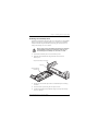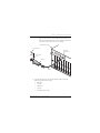
1
CAMPUS-REX2 RS INTERFACE CARD
VERSION 5.1
USER MANUAL
Copyright
July 2003
© 2003 ADC Telecommunications, Inc. All rights reserved.
Trademark Information
ADC and ADC Telecommunications are registered trademarks of ADC
Telecommunications, Inc. StarGazer, Campus-Star, and Campus-REX are registered
trademarks of ADC Telecommunications, Inc
No right, license, or interest to such trademarks is granted hereunder, and you agree that
you shall assert no such right, license, or interest with respect to such trademarks. All other
product names mentioned in this document are used for identification purposes only and
may be trademarks or registered trademarks of their respective companies.
Information contained in this document is company private to ADC Telecommunications,
Inc., and shall not be modified, used, copied, reproduced or disclosed in whole or in part
without the written consent of ADC.
Information furnished by ADC Telecommunications, Inc. is believed to be accurate and
reliable. However, no responsibility is assumed by ADC Telecommunications, Inc. for its
use; nor for any infringement of patents or other rights of third parties which may result
from its use. No license is granted by implication or otherwise under any patent or patent
rights of ADC Telecommunications, Inc. ADC Telecommunications, Inc. reserves the right
to change specifications at any time without notice.
Disclaimer of Liability
Information contained in this document is company private to ADC DSL Systems, Inc., and
shall not be modified, used, copied, reproduced or disclosed in whole or in part without the
written consent of ADC.
Contents herein are current as of the date of publication. ADC reserves the right to change
the contents without prior notice. In no event shall ADC be liable for any damages resulting
from loss of data, loss of use, or loss of profits, and ADC further disclaims any and all
liability for indirect, incidental, special, consequential or other similar damages. This
disclaimer of liability applies to all products, publications and services during and after the
warranty period.
ii
Campus-REX2 RS Interface Card User Manual
FCC Notice
FCC NOTICE
This unit complies with the limits for a Class A digital device, pursuant to
Part 15 of the FCC rules. These limits are designed to provide reasonable
protection against harmful interference in a residential installation. This
equipment generates, uses and can radiate radio frequency energy and, if not
installed and used in accordance with the instructions, may cause harmful
interference to radio communications. However, there is no guarantee that
interference will not occur in a particular installation. Testing on older
Campus-RS models was performed at 3.072 Mbps. If this equipment does
cause harmful interference to radio or television reception, which can be
determined by turning the equipment off and on, the user is encouraged to try
to correct the situation by one or more of the following measures:
•
Reorient or relocate the receiving antenna.
•
Increase the separation between the equipment and the receiver.
•
Consult the dealer or an experienced radio or television technician
for help.
Any changes or modifications not expressly approved by the grantee of this
device voids the user’s authority to operate the equipment.
Campus-REX2 RS Interface Card User Manual
iii
Using This Manual
USING THIS MANUAL
This manual provides installation, configuration and management procedures
for using the ADC Campus® Remote Ethernet eXpress2 (Campus-REX2®)
RS interface card. It includes procedures to:
•
install the card in either a Campus-RS™ desktop unit (150-1158-01,
150-1158-02, 150-1158-51, or 150-1158-52) or Campus-Star® chassis
(150-1220-01, 150-1220-02, or 150-1220-51)
•
configure the Campus-REX2 using the LCD and buttons
•
configure the Campus-REX2 using the command-line interface
•
monitor the Campus-REX2 performance
•
perform testing on the Campus-REX2
•
contact ADC for assistance
DOCUMENT CONVENTIONS
Messages identified by icons shown below may appear in the text.
Notes contain information about special circumstances.
Cautions indicate the possibility of personal injury or
equipment damage.
The Electrostatic Discharge (ESD) symbol indicates that a
device or assembly is susceptible to damage from
electrostatic discharge.
iv
Campus-REX2 RS Interface Card User Manual
Document Conventions
The following conventions are used in this manual:
•
This font indicates text that appears on the LCD or terminal.
•
Keycaps, such as
keyboard.
•
Names in bold font indicate buttons on the desktop unit or line unit that
you press.
ESC
, indicate keys that you press on a terminal
For a list of abbreviations used in this manual, see “Abbreviations” on page
143.
This table describes the manuals and guides in the Campus-RS
documentation set.
Document
Description
Campus-Star User
Manual
Contains instructions for setting up and using a
Campus-Star. The manual includes instructions for
installing line units and interface cards into the
Campus-Star chassis.
Campus-RS Line Unit
User Manual
Describes the features of the Campus-RS line unit
and provides installation instructions.
Campus-RS Desktop
Unit User Manual
Describes the features of the Campus-RS desktop
unit and provides instructions for installing interface
cards, and connecting the unit to an HDSL line.
Campus Interface Card
User Manuals
Describes the features of the individual Campus
interface cards, one card per manual, and contains
instructions for configuring and monitoring the
system through the cards.
Campus-REX2 RS Interface Card User Manual
v
Unpack and Inspect the Shipment
UNPACK AND INSPECT THE SHIPMENT
Upon receiving the Campus-REX2 RS Interface Card:
1
Unpack the card and inspect it for signs of damage. If it has been
damaged in transit, report the extent of the damage to the transportation
company and to your sales representative immediately. Order
replacement equipment if necessary.
2
Compare the contents of the package against the packing list to ensure a
complete and accurate shipment. If the shipment is incomplete or
incorrect, contact ADC as described in “Contacting ADC” on page 145.
If you need to store the unit for several days or more before installing it, return
it to the original packaging.
vi
Campus-REX2 RS Interface Card User Manual
Table of Contents
TABLE OF CONTENTS
Chapter 1: Installing and Accessing the REX2 ____________ 1
Installing the Campus-REX2.................................................................. 2
Installing into a Desktop Unit .................................................. 3
Installing into a Campus-Star Chassis ..................................... 4
Connecting the Ethernet Line................................................................. 5
Powering Up and Checking the Connection .......................................... 7
Setting Up Access to the Campus Unit .................................................. 8
Connecting to the Campus Unit Console Port ......................... 9
Logging In ............................................................................................ 12
Logging In a Campus Unit Using Telnet............................... 12
Logging In a Local Campus Unit through the Console Port . 13
Logging On a Remote Campus Unit...................................... 15
Logging Off.......................................................................................... 16
Using the Menus................................................................................... 16
Operating with Default Values............................................................. 17
Chapter 2: Configuring HDSL Parameters ______________ 19
Configuring HDSL Parameters ............................................................ 20
Accessing HDSL Configuration ............................................ 20
Selecting HDSL Parameters .................................................. 21
Configuring HDSL Alarms .................................................................. 26
Accessing HDSL Alarms Configuration ............................... 26
Setting HDSL Alarms ............................................................ 27
Chapter 3: Configuring the REX2 _____________________ 29
Accessing the REX2 Configuration and Status Screen........................ 30
Campus-REX2 RS Interface Card User Manual
vii
Table of Contents
Configuring the Campus-REX2 as a Bridge.........................................30
Configuring Bridge Protocol, Encapsulation and Timing......31
Configuring Bridge Features ..................................................32
Saving the Bridge Configuration............................................40
Accessing the Bridge and ARP Tables...................................41
Configuring the Campus-REX2 as a Router.........................................44
Configuring Routing Protocol, Encapsulation and Timing....45
Configuring Routing Features ................................................46
Configuring DHCP Services ..................................................53
Saving the Router Configuration............................................55
Accessing the Routing Tables ................................................56
Configuring the Campus-REX2 for SNMP Management ....................60
Accessing the SNMP Configuration ......................................60
Entering SNMP Parameters....................................................61
Enabling Authentication Error Trap Generation ....................62
Configuring Trap Receivers ...................................................63
Chapter 4: Managing System Parameters _______________ 65
Accessing System Configuration..........................................................66
Setting the Time and Date ....................................................................67
Identifying the Unit and Circuit............................................................67
Setting a Password ................................................................................69
Restoring Default Values......................................................................70
Viewing Product Information ...............................................................72
Chapter 5: Monitoring and Testing the Campus System ___ 73
Monitoring HDSL Performance ...........................................................74
Monitoring Current System Status .........................................75
viii
Campus-REX2 RS Interface Card User Manual
Table of Contents
Viewing 24-Hour Performance History................................. 76
Viewing Seven-Day Performance History............................. 77
Viewing Local Alarm History ............................................... 79
Viewing Ethernet Statistics .................................................................. 80
Viewing Bridge Statistics ...................................................... 81
Viewing Router Statistics ...................................................... 83
Performing Tests .................................................................................. 85
Performing Loopback Testing ............................................... 87
Resetting the Campus Unit................................................................... 89
Chapter 6: Managing Software________________________ 91
Upgrading Campus Unit Software ....................................................... 92
Recovering Software ............................................................................ 95
Chapter 7: Using the LCD for Configuration and
Management _____________________________ 97
Navigating the LCD Menus ................................................................. 98
Setting the HDSL Parameters............................................................... 99
Accessing LCD HDSL Configuration ................................. 100
Configuring Standard Mode ................................................ 100
Configuring Extended Mode Parameters............................. 101
Configuring the Campus-REX2 ........................................................ 103
Accessing LCD REX2 Configuration.................................. 104
Configuring REX2 Parameters ............................................ 104
Saving the REX2 Configuration .......................................... 108
Restoring the System to Default Values............................................. 108
Viewing and Configuring Alarms ...................................................... 109
HDSL Alarms ...................................................................... 109
Campus-REX2 RS Interface Card User Manual
ix
Table of Contents
Local Alarms ........................................................................111
Remote Alarms.....................................................................112
Configuring Loopbacks ......................................................................113
Initiating a Loopback............................................................114
Clearing a Loopback ............................................................114
Setting the Loopback Timeout .............................................114
Viewing System Information..............................................................115
Viewing Status Information................................................................115
Ethernet Information ............................................................116
HDSL Margin.......................................................................116
Port Statistics ......................................................................................116
Bridge Port Statistics ............................................................117
Router Port Statistics ............................................................118
Chapter 8: Internetworking and Management Overview__ 119
Composition of a Campus-RS System................................................120
Application..........................................................................................121
Point-to-Point LAN Extension .............................................122
LAN Connections Over a WAN ..........................................123
MAC-Level Bridging and Spanning Tree Protocol............................124
About MAC-Level Bridging ................................................124
About Spanning Tree Protocol .............................................124
IP Routing ...........................................................................................126
Static Routing .......................................................................126
Dynamic Routing .................................................................129
Campus-REX2 IP Addresses................................................129
Management Protocols .......................................................................132
SNMP ...................................................................................132
x
Campus-REX2 RS Interface Card User Manual
Table of Contents
Telnet ................................................................................... 133
FTP....................................................................................... 133
MIB and Trap Support ....................................................................... 133
DHCP ................................................................................................. 134
Encapsulation Protocols ..................................................................... 135
Product Compatibility ........................................................................ 136
Compatibility with Earlier Campus Products ...................... 136
Compatibility with Campus-RS Products............................ 137
Compatibility with Earlier Versions of Campus Products... 138
Appendix A: Technical Reference _____________________ 139
Specifications ..................................................................................... 139
Default Settings .................................................................................. 140
Ethernet Port....................................................................................... 141
Standards ............................................................................................ 141
Appendix B: Abbreviations __________________________ 143
Appendix C: Contacting ADC ________________________ 145
Campus-REX2 RS Interface Card User Manual
xi
Table of Contents
xii
Campus-REX2 RS Interface Card User Manual
INSTALLING AND
ACCESSING THE REX2
1
The Campus-REX2 RS is a 10/100Base-T Ethernet interface card that
provides:
•
IEEE 802.1d transparent MAC level bridging with Spanning Tree
protocol support
•
static and dynamic IP Routing
•
DHCP relay
•
DHCP client
•
cHDLC or PPP frame encapsulation options
•
FTP server for transferring software upgrades
•
VLAN support that accommodates forwarding larger-sized packets
•
embedded Simple Network Management Protocol Version 1
(SNMP V1) agent
The following sections provide instruction to install the Campus-REX2 and
access it for configuration and management.
For:
See Page:
Installing the Campus-REX2
2
Connecting the Ethernet Line
5
Powering Up and Checking the Connection
7
Setting Up Access to the Campus Unit
8
Logging In
12
Logging Off
16
Using the Menus
16
Operating with Default Values
17
Campus-REX2 RS Interface Card User Manual
1
Chapter 1 - Installing and Accessing the REX2
The Campus-REX2 can be installed into either a Campus-Star chassis
(paired with a Campus-RS or -HRS Line Unit) or into a Campus-RS or -HRS
desktop unit. The , installed into either, provides one end of a High-bit-rate
Digital Subscriber Line (HDSL) transmission system. When connected to
another Campus-RS, Campus-HRS, Campus-T1®, Campus-768®, or
Campus-E1® desktop unit or a line unit in another chassis, the Campus
system transports digitized voice, data, and video signals over existing copper
wire at an HDSL rate specified by the user from a range of rates up to 4.608
Mbps.
When the Campus-REX2 is installed in a Campus-HRS desktop unit or with
a Campus-HRS line unit (or older), only T1, E1, and 768 Mbps data rates are
supported.
INSTALLING THE CAMPUS-REX2
The following sections describe how to install the Campus-REX2 RS
Interface Card into either a:
•
Campus desktop unit on page 1-3
•
Campus-Star chassis on page 1-4
Ensure that the Campus-REX2 is installed into a Campus-RS
or Campus-HRS desktop unit or into a Campus-Star chassis
with a Campus-RS or Campus-HRS line unit only. The
Campus-REX2 will not operate if it is installed in an earlier
version of these Campus products.
Ensure that you read important information on surge
protection for HDSL line installation in the line unit or desktop
unit manual before installing the Campus-REX2 interface
card.
For information about compatibility between the Campus-REX2 and other
Campus products, refer to “Product Compatibility” on page 136.
For information about products that comprise a Campus system, refer to
“Composition of a Campus-RS System” on page 120.
2
Campus-REX2 RS Interface Card User Manual
Chapter 1 - Installing and Accessing the REX2
Installing into a Desktop Unit
Install the Campus-REX2 interface card into a Campus-RS or Campus-HRS
desktop unit before you install the desktop unit (install power and HDSL
cables). Install the Campus-RS desktop unit using the instructions in the
Campus-RS Desktop Unit User Manual.
Ensure power is off to the desktop unit before you install the
Campus-REX2. Installing the card with the power on may
cause damage to the desktop unit, the card, or to both.
1
Ensure that the desktop unit is not connected to power.
2
Slide the Campus-REX2 into the guide rails in the rear of the
desktop unit.
Campus-RS Desktop Unit chassis
Guide rail
Campus-REX2 RS
Interface card
CA
MP
US
-R
S
1
or 20 V
22 AC
0V @
6
.2AAC@0H
z
Ma 50
x Hz
HU
Lin
k/A
cti
vit
y
B
MD
I
MD
I-X
PC
RE
X2
Ro
ute
r
CO
NS
LIN
OL
E
E
10
10 Bas
0
Bae-T
se
-T
x
3
Gently press the card into place until it is seated firmly in the mating
connector.
4
Secure the card in place using the two captive screws.
5
Complete the desktop unit installation using the Campus-RS Desktop
Unit User Manual.
Campus-REX2 RS Interface Card User Manual
3
Chapter 1 - Installing and Accessing the REX2
Installing into a Campus-Star Chassis
The Campus-REX2 must be installed into a Campus-Star chassis first, before
you install the corresponding Campus-RS or Campus-HRS line unit.
The Campus-REX2 is not hot-swappable. Damage may occur
to the Campus-REX2, the line unit, or both if the line unit is
installed before you install the Campus-REX2.
Ensure that a line unit is not installed in the line-unit slot corresponding
to the slot where you will install the Campus-REX2.
2
Slide the Campus-REX2 into the guide rails of the selected slot at the rear
of the Campus-Star chassis.
620
DSX-1/T
CFG
10 Base-T
100 Base-Tx
PC
HUB
MDI
Link/Activity
Campus-Star
chassis
MDI-X
REX2 Router
620
DSX-1/T
CFG
DSX-1
DSX-1
1
Campus-REX2 RS Interface card
4
Campus-REX2 RS Interface Card User Manual
Chapter 1 - Installing and Accessing the REX2
3
Gently press the card into place until it is seated firmly in the mating
connector.
4
Secure the card in place using the two captive screws.
5
Install a Campus-RS line unit and connect it to an HDSL line using the
Campus-RS Line Unit User Manual. The line unit provides the DSL
connection for the interface card.
CONNECTING THE ETHERNET LINE
The 10 Base-T and 100 Base-Tx (10/100Base-T) port on the rear panel of the
Campus-REX2 connects to a LAN through a hub, repeater, or another router.
The port autosenses both the 10/100Base-T port rate and half- or full-duplex
mode of the network device to which it connects and matches the
configuration.
Use a straight-through Category 5 cable to connect the Ethernet port. Set the
MDI/MDI-X switch to the appropriate position, dependent on the device to
which you are connecting.
1
Set the Campus-REX2 MDI/MDI-X switch to one of the following:
•
MDI-X when connecting to
network equipment such as
an Ethernet NIC in a PC or
any other equipment that has
an MDI port
Use when connecting
to an MDI port such as
a PC Ethernet NIC
MDI-X
Use when connecting
•
MDI
to an MDI-X port such as
MDI when connecting to
a hub, switch, or router
network equipment such as a
hub, switch, or router or any other equipment that has an
MDI-X port
Campus-REX2 RS Interface Card User Manual
5
Chapter 1 - Installing and Accessing the REX2
2
Plug one end of the Category 5 cable into the 10/100Base-T connector on
the Campus-REX2 faceplate.
Campus-RS Desktop Unit
PC, hub, router or
other Ethernet equipment
Ethernet port
Lin
HU
B
RE
k/A
cti
vit
y
MD
I
MD
I-X
PC
10 Base-T
100 Base-Tx port
X2
Ro
ute
r
10
10 Bas
e
0
Ba -T
se
-T
x
1
or 20 V
22 AC
0V @
6
.2AAC@0H
z
Ma 50
x Hz
Category 5 cable
The Campus-REX2 10/100Base-T interface operates in either
half- or full-duplex mode which is determined by autosensing
its network connection. Both the LCD menu and console
menu displays the mode.
3
6
Connect the other end of the Ethernet cable to the local Ethernet
equipment (repeater, PC NIC, or other Ethernet device).
Campus-REX2 RS Interface Card User Manual
Chapter 1 - Installing and Accessing the REX2
POWERING UP AND CHECKING THE CONNECTION
Verify operating status after completing a full installation that includes
installing of the Campus-REX2 into a desktop unit or Campus-Star chassis
and then completing the installation of the desktop unit or the Campus-Star
chassis (including the Line Unit):
1
Verify that the power cord is connected to the desktop unit or to the
Campus-Star chassis (if you have an AC power supply) and to an
external power source. Then verify the powerup of and HDSL
connection for that unit as specified in the appropriate user manual.
2
If the Campus-REX2 is installed in a desktop unit, press the power button
to On. The button is located on the back of the desktop unit.
3
Verify that the Link LED on the Campus-REX2 card is green. This
indicates that the 10/100Base-T connection is operating correctly. If the
Link LED does not light green, check the 10/100Base-T cabling
configuration.
If the link LED does not light green, check that the MDI/MDI-X switch
is set to the appropriate position.
Campus-REX2 RS Interface Card User Manual
7
Chapter 1 - Installing and Accessing the REX2
SETTING UP ACCESS TO THE CAMPUS UNIT
Configure a Campus system through any of the following:
•
a PC connected to the desktop unit Console port
•
a PC connected to the Campus-Star line unit Console port
•
a telnet session to the Campus-REX2 over the Internet or the CMU in a
Campus-Star chassis
•
the LCD menu and buttons on the desktop unit or CMU front panel
•
StarGazer or a comparable EMS using SNMP
A Console port or telnet connection provides access to configuration menus
that provide options not available through the LCD menus. Depending on
your immediate configuration requirements, you may not need to set up a PC
immediately. Use the Console port or a telnet session when you:
•
configure the Campus-REX2 as a router (only some bridging and routing
configuration is available using the LCD)
•
want to change the HDSL transmission rate and do not want to use the
LCD menus
•
will set additional configuration options at this time, such as system or
REX2
•
want to view performance statistics for the HDSL and 10/100Base-T
interfaces
If you want to set up a PC at this time, refer to “Setting Up Access to the
Campus Unit” on page 8.
8
Campus-REX2 RS Interface Card User Manual
Chapter 1 - Installing and Accessing the REX2
Connecting to the Campus Unit Console Port
Use a terminal or a PC with terminal emulation software (both will be referred
to as PC) connected to the Console port to configure Campus system options,
manage the unit, and generate system reports. The PC connects to the Console
port on the desktop unit, the line unit (in a Campus-Star chassis), or the
CMU-810 installed in the Campus-Star chassis.
1
Connect the Console adapter into the standard 9-pin COM port on the PC
and tighten the attached screws.
2
Plug one end of the console cable into the PC’s COM port or console
adapter, then do one of the following:
•
If the Campus-REX2 is installed into a desktop unit, connect the
other end of the console cable into the desktop unit Console port.
PC or terminal
Campus-RS Desktop Unit
9-pin COM
port
Console port
Lin
k/A
B
RE
cti
vit
y
HU
MD
MD
I-X
PC
Console adapter
X2
Ro
ute
r
I
10
10 Bas
e
0
Ba -T
se
-T
x
1
or 20 V
22 AC
0V @
6
.2AAC@0H
z
Ma 50
x Hz
Black cable
(Category 3)
Campus-REX2 RS Interface Card User Manual
9
Chapter 1 - Installing and Accessing the REX2
•
If the Campus-REX2 is installed in a Campus-Star chassis, do one
of the following:
–
plug the other end of the console cable into the Console port on
the front of the line unit
Campus-Star chassis
CM
U71
0
MA
NA
GE
ME
NT
PO
W
ER
Console port
UN
IT
SL
OT
PC or terminal
AL
AR
MS
MA
MINJOR
AC OR
O
Ca
mp
LIN us H
R
E
UN S
IT
Ca
mp
LIN us H
R
E
UN S
IT
RE
S
ET
Ca
mp
LIN us H
R
E
UN S
IT
HD
SL
TE
ST
Ca
mp
LIN us H
R
E
UN S
IT
HD
PO
SL
RT
TE
ST
Ca
mp
LIN us H
R
E
UN S
IT
HD
PO
SL
RT
TE
ST
9-pin COM
port
Ca
mp
LIN us H
R
E
UN S
IT
HD
PO
SL
RT
TE
RS
CO -23
NS 2
OL
E
ST
Ca
mp
LIN us H
R
E
UN S
IT
HD
PO
SL
RT
TE
RS
CO -23
NS 2
OL
E
ST
Ca
mp
LIN us H
R
E
UN S
IT
HD
PO
SL
RT
TE
RS
CO -23
NS 2
OL
E
ST
Ca
mp
LIN us H
R
E
UN S
IT
HD
PO
SL
RT
TE
RS
CO -23
NS 2
OL
E
ST
HD
PO
SL
RT
TE
RS
CO -23
NS 2
OL
E
ST
HD
PO
SL
RT
TE
RS
CO -23
NS 2
OL
E
ST
PO
RT
RS
CO -23
NS 2
OL
E
RS
CO -23
NS 2
OL
E
RS
CO -23
NS 2
OL
E
Category 3 Cable
10
Campus-REX2 RS Interface Card User Manual
Chapter 1 - Installing and Accessing the REX2
–
plug the other end of the console cable into the Console port of
the CMU-810 Management unit (when installed), as described
in the Campus-Star with CMU-810 User Manual
Campus-Star chassis
PC or terminal
CM
UAL
81
AR
0
MA
JO
MIN
R
MA
NA
GE
ME
NT
UN
IT
OR
AC
O
NE
Ca
mp
LIN us H
R
E
UN S
IT
XT
EN
TE
EP
S
SL
Ga
SL
TE
ST
RS
SL
TE
ST
PO
2
Ca
mp
LIN us H
R
E
UN S
IT
HD
SL
RT
TE
ST
Adapter
-23
Ca
mp
LIN us H
R
E
UN S
IT
HD
RT
in
OT
Ca
mp
LIN us H
R
E
UN S
IT
HD
PO
Pa
ir
R
Ca
mp
LIN us H
R
E
UN S
IT
9-pin COM
port
CMU-810
Console port
MS
Ca
mp
LIN us H
R
E
UN S
IT
HD
PO
SL
RT
TE
RS
CO -23
NS 2
OL
E
ST
Ca
mp
LIN us H
R
E
UN S
IT
HD
PO
SL
RT
TE
RS
CO -23
NS 2
OL
E
ST
SL
RT
TE
RS
CO -23
NS 2
OL
E
ST
TE
ST
HD
PO
P
SL
RT
TE
RS
CO -23
NS 2
OL
E
r
ST
PO
HD
P
SL
RT
TE
RS
CO -23
NS 2
OL
E
ai
r
ST
PO
RT
RS
CO -23
NS 2
OL
E
ai
r
Cable
SL
RT
ai
Ca
mp
LIN us
E
U
HD
PO
RS
CO -23
NS 2
OL
E
P
Ca
mp
LIN us H
R
E
UN S
IT
HD
PO
P
RS
CO -23
NS 2
OL
E
ai
r
RS
CO -23
NS
O
P
ai
r
P
ai
r
P
ai
r
P
ai
r
P
3
ai
r
Configure the terminal or PC terminal emulation software with the
following communications settings:
•
9600 baud
•
no parity
•
8 data bits
•
1 stop bit
•
no hardware flow control
Campus-REX2 RS Interface Card User Manual
11
Chapter 1 - Installing and Accessing the REX2
LOGGING IN
Access the Campus-REX2 menus for configuration and management using
any of these four logins, which can be concurrently connected:
•
a telnet session to the Campus-REX2 (see below)
•
a login to the local Campus unit through the Console port (see “Logging
In a Local Campus Unit through the Console Port” on page 13)
•
a logon from a remote Campus unit through its Main Menu (see
“Logging On a Remote Campus Unit” on page 15)
•
a login through the CMU in the Campus-Star chassis
Logging In a Campus Unit Using Telnet
Use telnet protocol to access the
Campus unit for configuration and
management over the Internet. From the
Windows Start menu, select Run. Enter
the telnet command and the IP address
for the Campus-REX2 (default IP
address is 192.168.1.1). The timeout for
disconnecting a telnet session is five minutes (time frame with no keyboard
activity to the Campus unit). The following login screen is displayed:
TELNET LOGIN PASSWORD >
Enter the configured password (default password is
Campus-REX2 Main Menu.
12
ENTER )
to log on the
Campus-REX2 RS Interface Card User Manual
Chapter 1 - Installing and Accessing the REX2
Logging In a Local Campus Unit through the Console Port
You previously set up the terminal communication settings (Step 3 on page
1-11) for your PC to access the Campus unit. From your terminal emulation
software or your terminal, do the following:
1
Press the SPACEBAR on the PC keyboard several times until the baud rate
is established and the Login Password screen is displayed as shown
below.
Jul 07, 2003
ADC TELECOMMUNICATIONS, CAMPUS RS, Version 5.1 08:19:34
Local Unit ID:
Local I/F: REX2
Remote Unit ID: Inactive
Remote I/F: Inactive
Circuit ID:
LOGIN PASSWORD >
If the system does not respond when you attempt to log on, ensure that
hardware flow control is turned off in the terminal emulation software on
the PC or for the terminal.
Campus-REX2 RS Interface Card User Manual
13
Chapter 1 - Installing and Accessing the REX2
2
Press ENTER (default password) to log on. If a password was previously
configured, type that password then press ENTER . The Main Menu is
displayed.
Jul 07, 2003
ADC TELECOMMUNICATIONS, CAMPUS RS, Version 5.1 08:19:34
Local Unit ID:
Local I/F: REX2
Remote Unit ID: Inactive
Remote I/F: Inactive
Circuit ID:
MAIN MENU
1)
2)
3)
4)
SYSTEM STATUS
REX2 CONFIGURATION AND STATUS
SYSTEM CONFIGURATION
MAINTENANCE
5)
REMOTE LOGON
(L)ogout
ENTER CHOICE>
Once you are logged into the Campus unit through the console port, there is
no timeout defined for the session. You will stay connected until you either
log out or the Campus unit detects a disconnected console cable (DTR signal
changes to inactive).
14
Campus-REX2 RS Interface Card User Manual
Chapter 1 - Installing and Accessing the REX2
Logging On a Remote Campus Unit
Log on the remote Campus unit which is at the far end of the HDSL
connection from the local Campus unit you are logged into. The remote
Campus unit is accessed through the Main Menu of the local Campus unit:
1
From the Main Menu of the local Campus-REX2, type
ENTER . The following message is displayed:
5
then press
Enter <ESC><ESC> to Exit Remote Login Mode.
Remote Login, Please wait. . . . . .
You can exit from this function or from the remote login by pressing
ESC twice. The following logon screen is displayed.
Jul 07, 2003
ADC TELECOMMUNICATIONS, CAMPUS RS, Version 5.1 08:19:34
Local Unit ID: Southall Quad 4
Local I/F: REX2
Remote Unit ID: Central
Remote I/F: REX2
Circuit ID:
Southeast line 421
REMOTE_LOGON PASSWORD >
The menu header changes to indicate the remote unit ID as the local unit,
and local unit ID as the remote. This shows that the terminal program is
physically connected to the local unit, but is configuring as if it were
connected to the remote unit.
If the remote unit is also a Campus-REX2, the screens and procedures on
the Remote Main Menu are identical to those on the Local Main Menu,
except the REMOTE LOGON option is not available. If the remote unit
is not a Campus-REX2, the screens support that remote interface card
(see the appropriate interface card user manual for a description of the
screens and configuration options).
Campus-REX2 RS Interface Card User Manual
15
Chapter 1 - Installing and Accessing the REX2
LOGGING OFF
From the Main Menu, type L then press ENTER to logout of the unit menus.
If the Main Menu is not the current menu, type R or M (when available) then
press ENTER to return to the Main Menu where you can logout as described
above. The logout procedure is the same whether you are connected to the
console port or through a telnet session.
USING THE MENUS
The bottom of each menu screen identifies all of the keys you can use on that
screen. Several keys operate identically on all of the menu screens:
To:
Do this:
Access menu items
Type the number of the item then press ENTER .
Return to the previous menu Type R then press ENTER .
Return to the Main Menu
Type M then press ENTER when the menu is more
than one level below the Main Menu.
Clear or update status
information
• Type C then press ENTER to clear or reset the
information on a status screen.
• Type U then press ENTER to update the
information on a status screen.
Configure options as described below:
16
For this option type:
Do this:
Select a value from a list of
predefined values
1 Type the number of the option then press ENTER .
The option setting changes to the next value in the
list and the screen redraws.
2 Repeat the first step until the option is set to the
preferred value.
Type in required information
1 Type the number of the option then press ENTER .
The screen prompts you for information.
2 Type the information in the format requested then
press ENTER .
Campus-REX2 RS Interface Card User Manual
Chapter 1 - Installing and Accessing the REX2
When you have selected or entered configuration changes for some
parameters such as bridging or routing, you must save those changes for them
to be permanent (saved if power to the Campus-REX2 is cycled). Type R
from a configuration screen until you return to the root for that configuration
and then save the changes. For example, the REX2 Configuration and Status
screen is the root for REX2 configuration.
OPERATING WITH DEFAULT VALUES
Campus-REX2 can be operated using its default settings which include:
•
HDSL Operating Mode set to Standard Mode
•
Standard Mode HDSL Rate set to T1
•
network protocol set to bridge, with the encapsulation format set to
cHDLC
•
Spanning Tree protocol disabled
•
Timing Source set to Internal
Set other configurable options to customize the Campus system to your
network requirement as described in the following chapters. The LAN port
has a default IP address assigned (192.168.1.1) that you can change to fit your
IP networking scheme.
Campus-REX2 RS Interface Card User Manual
17
Chapter 1 - Installing and Accessing the REX2
18
Campus-REX2 RS Interface Card User Manual
CONFIGURING
HDSL PARAMETERS
2
Campus units have a default HDSL configuration to operate in Standard
Mode with a T1 (1.544 Mbps) HDSL Rate. This default configuration is
compatible with other Campus-RS and Campus-HRS products (including the
Campus-T1 desktop units and line units) if you choose to operate them in
their default configuration.
For:
See Page:
Configuring HDSL Parameters
20
Configuring HDSL Alarms
26
You can also configure the HDSL parameters through the LCD menus.
See “Using the LCD for Configuration and Management” on page 7-97
for instructions on using the LCD panel. To view system performance and
other status information, see “Monitoring and Testing the Campus System”
on page 5-73.
Changes to the HDSL operating mode or transmission rate are
not automatically made to the remote unit. These changes
must be made at both the local and remote units for the HDSL
link to be re-established. If the remote unit is not easily
accessible, you can follow the instructions in “Logging On a
Remote Campus Unit” on page 1-15 to use a PC for a remote
logon (if an HDSL link is up) and make the preferred change.
When you change the HDSL settings on the remote unit, the
HDSL link is lost; it is re-established when you make the
identical change(s) on the local unit.
Campus-REX2 RS Interface Card User Manual
19
Chapter 2 - Configuring HDSL Parameters
CONFIGURING HDSL PARAMETERS
Access the HDSL configuration screen, then configure parameters.
Accessing HDSL Configuration
From the Main Menu (page 14), type
System Settings Menu.
3
then press
ENTER
to access the
Jul 07, 2003
ADC TELECOMMUNICATIONS, CAMPUS RS, Version 5.1 08:19:34
Local Unit ID:
Local I/F: REX2
Remote Unit ID: Inactive
Remote I/F: Inactive
Circuit ID:
SYSTEM SETTINGS MENU
1)
2)
SYSTEM PARAMETERS
HDSL PARAMETERS
(R)eturn
ENTER CHOICE>
From the System Settings Menu, type 2 then press ENTER to access the
HDSL Parameters screen. From this screen, you can configure or change
values. Standard Mode is the default HDSL Parameters screen.
Jul 07, 2003
ADC TELECOMMUNICATIONS, CAMPUS RS, Version 5.1 08:19:34
Local Unit ID:
Local I/F: REX2
Remote Unit ID: Inactive
Remote I/F: Inactive
Circuit ID:
STANDARD MODE HDSL PARAMETERS
1) HDSL Operating Mode:
2) Transceiver Mode:
3) HDSL Rate:
Standard
Auto
T1
(Standard, Extended)
(Auto, Master, Slave)
(T1, E1, 768)
Enter (S)ave to apply changes !
(S)ave
(R)eturn
(M)ain Menu
ENTER CHOICE>
20
Campus-REX2 RS Interface Card User Manual
Chapter 2 - Configuring HDSL Parameters
Selecting HDSL Parameters
You can use the default HDSL setting for your Campus-RS unit (when also
using the default settings on the remote unit to which this unit connects)
which are:
•
standard for the HDSL operating mode
•
auto for the transceiver mode (determines which device is the master
or slave)
•
T1 for the HDSL rate
If you want to change any of these parameters, select one of the following
sections based on the HDSL operating mode you will use. Campus-RS offers
these two HDSL operating modes:
•
•
Standard mode (page 22) provides compatibility between a Campus-RS
product and an earlier Campus product (legacy Campus) that has a
HDSL interface including T1, E1, or 768:
–
for T1, the maximum transmission rate is 1.544 Mbps over 2 pairs
–
for E1, the maximum transmission rate is 2.048 Mbps over 2 pairs
–
for 768, the transmission rate is 768 kbps over 1 pair
Extended mode (page 23) provides a fractional rate selection between the
HDSL interfaces of two Campus-RS products. The rate is selectable as
follows:
–
for 1 pair in 64 kbps increments, starting at 128 kbps up to
2.304 Mbps
–
for 2 pair in 128 kbps increments, starting at 256 kbps up to
4.608 Mbps
Campus-REX2 RS Interface Card User Manual
21
Chapter 2 - Configuring HDSL Parameters
Using Standard Mode
Standard mode is the default configuration for the HDSL operating mode.
When standard mode is selected, only three HDSL rates (T1, E1, and 768) are
available. You can select any of the three options for transceiver mode,
however.
1
From the HDSL Parameters menu, type 1 then press ENTER if the
HDSL Operating Mode is set to Extended. Standard is now displayed as
the HDSL Operating Mode.
It is recommended that you leave the Transceiver Mode
option set to Auto unless you require that a particular end of
the HDSL connection be the Master or Slave.
Also, this value cannot be changed if the HDSL link is up.
2
To change the Transceiver Mode, type 2 then press ENTER . The
Transceiver Mode changes to the next setting. Repeat until the preferred
setting is selected:
•
Master initiates the HDSL link. The other Campus unit must be set
to Slave or Auto.
•
Slave waits for the other Campus unit to initiate the HDSL link. The
other unit must be set to Master or Auto.
•
Auto (default) automatically switches between Master and Slave
until an HDSL link is established.
The Transceiver Mode option determines the hierarchy of the two
Campus units when attempting to establish an HDSL link.
3
To change the HDSL Rate, type 3 then press ENTER . The HDSL Rate
changes to the next setting. Repeat until the HDSL Rate is set to the
preferred setting of T1 (default), E1, or 768.
4
Type
S
to save and apply HDSL changes as prompted by:
Enter (S)ave to apply changes !
5
22
To exit the menu, type
Menu).
R
(go back one screen) or
M
(return to the Main
Campus-REX2 RS Interface Card User Manual
Chapter 2 - Configuring HDSL Parameters
Using Extended Mode
With Extended mode, the HDSL link can comprise either one or two loops
with a rate selection in 64 (1 pair) or 128 (2 pair) kbps increments. The
transmission rate between two Campus-RS products is up to 4.608 Mbps with
two pair or 2.304 Mbps with one pair. Both the one loop network or two loop
network operate only in full-duplex transmission.
1
From the HDSL Parameters menu, type 1 then press ENTER . The
HDSL Operating Mode options changes from Standard to Extended as
shown below.
Jul 07, 2003
ADC TELECOMMUNICATIONS, CAMPUS RS, Version 5.1 08:19:34
Local Unit ID:
Local I/F: REX2
Remote Unit ID: Inactive
Remote I/F: Inactive
Circuit ID:
EXTENDED MODE HDSL PARAMETERS
1)
2)
3)
4)
HDSL Operating Mode:
Transceiver Mode:
HDSL Loop Mode:
HDSL Rate:
Extended
Auto
2 Loops
256
(Standard, Extended)
(Auto, Master, Slave)
(1 Loop, 2 Loops)*
*Note:
1 Loop = single loop, full duplex
2 Loops = two loops, full duplex
Enter (S)ave to apply changes !
(S)ave
(R)eturn
(M)ain Menu
ENTER CHOICE>
Campus-REX2 RS Interface Card User Manual
23
Chapter 2 - Configuring HDSL Parameters
It is recommended that you leave the Transceiver Mode
option set to Auto unless you require that particular ends of
the HDSL connection be the Master and Slave.
Also, this value cannot be changed if the HDSL link is up.
2
To change the Transceiver Mode, type 2 then press ENTER . The
Transceiver Mode changes to the next setting. Repeat until the preferred
setting is selected:
•
Master initiates the HDSL link. The other Campus unit must be set
to Slave or Auto.
•
Slave waits for the other Campus unit to initiate the HDSL link. The
other unit must be set to Master or Auto.
•
Auto (default) automatically switches between Master and Slave
until an HDSL link is established.
The Transceiver Mode option determines the hierarchy of the two
Campus units when attempting to establish an HDSL link.
24
3
To change the HDSL Loop Mode from 1 Loop (default) to 2 Loop, type
3 then press ENTER .
4
To select an HDSL Rate, type 4 then press ENTER . The Select HDSL
Rate screen that is displayed is dependent on whether you selected
1 Loop or 2 Loop for the HDSL Loop Mode. The minimum and
maximum rates are:
•
for 1 Loop, 128 kbps is the minimum and 2304 Mbps is the
maximum selected in 64 kbps increments; the default is 128 kbps
•
for 2 Loop, 256 kbps is the minimum and 4608 Mbps is the
maximum selected in 128 kbps increments; the default is 256 kbps
Campus-REX2 RS Interface Card User Manual
Chapter 2 - Configuring HDSL Parameters
Choose a rate from one of the following:
•
For 1 Loop, the Select HDSL Low Rate screen is displayed. To
select a rate, type a number from 2 to 36 then press ENTER .
Jul 07, 2003
ADC TELECOMMUNICATIONS, CAMPUS RS, Version 5.1 08:19:34
Local Unit ID:
Local I/F: REX2
Remote Unit ID: Inactive
Remote I/F: Inactive
Circuit ID:
SELECT HDSL LOW RATE
Current HDSL Rate:
Current Loop Mode:
1)
2)
3)
4)
5)
6)
7)
8)
9)
10)
11)
12)
N/A
128
192
256
320
384
448
512
576
640
704
768
kbps
kbps
kbps
kbps
kbps
kbps
kbps
kbps
kbps
kbps
kbps
128
1 Loop
13) 832 kbps
14) 896 kbps
15) 960 kbps
16) 1024 kbps
17) 1088 kbps
18) 1152 kbps
19) 1216 kbps
20) 1280 kbps
21) 1344 kbps
22) 1408 kbps
23) 1472 kbps
24) 1536 kbps
(R)eturn (M)ain Menu
25)
26)
27)
28)
29)
30)
31)
32)
33)
34)
35)
36)
1600
1664
1728
1792
1856
1920
1984
2048
2112
2176
2240
2304
kbps
kbps
kbps
kbps
kbps
kbps
kbps
kbps
kbps
kbps
kbps
kbps
ENTER CHOICE>
•
For 2 Loop, the Select HDSL High Rate screen is displayed. To
select a rate, type a number from 2 to 36 then press ENTER .
Jul 07, 2003
ADC TELECOMMUNICATIONS, CAMPUS RS, Version 5.1 08:19:34
Local Unit ID:
Local I/F: REX2
Remote Unit ID: Inactive
Remote I/F: Inactive
Circuit ID:
SELECT HDSL HIGH RATE
Current HDSL Rate:
Current Loop Mode:
1)
2)
3)
4)
5)
6)
7)
8)
9)
10)
11)
12)
N/A
256
384
512
640
768
896
1024
1152
1280
1408
1536
kbps
kbps
kbps
kbps
kbps
kbps
kbps
kbps
kbps
kbps
kbps
256
2 Loops
13) 1664 kbps
14) 1792 kbps
15) 1920 kbps
16) 2048 kbps
17) 2176 kbps
18) 2304 kbps
19) 2432 kbps
20) 2560 kbps
21) 2688 kbps
22) 2816 kbps
23) 2944 kbps
24) 3072 kbps
(R)eturn (M)ain Menu
25)
26)
27)
28)
29)
30)
31)
32)
33)
34)
35)
36)
3200
3328
3456
3584
3712
3840
3968
4096
4224
4352
4480
4608
kbps
kbps
kbps
kbps
kbps
kbps
kbps
kbps
kbps
kbps
kbps
kbps
ENTER CHOICE>
5
Type
R
to exit the menu. (Typing
M
6
Type
S
to save and apply HDSL changes as prompted by:
will return you to the Main Menu.)
Enter (S)ave to apply changes !
Campus-REX2 RS Interface Card User Manual
25
Chapter 2 - Configuring HDSL Parameters
CONFIGURING HDSL ALARMS
You can configure options for four types of alarms:
•
HDSL ES Alarm Threshold determines the number of errored seconds
that must occur to trigger an alarm.
•
HDSL Margin Alarm Threshold determines the margin, in dB, that
triggers an alarm.
•
Alarm on Local I/F LOS lets you enable or disable the local Loss of
Signal alarm.
•
Alarm on Remote I/F LOS lets you enable or disable the remote Loss of
Signal alarm.
Access the configuration screen, then set the options.
Accessing HDSL Alarms Configuration
1
From the Main Menu (page 14), type
System Settings Menu.
Jul 07, 2003
Local Unit ID:
Remote Unit ID:
Circuit ID:
3
then press
ENTER
to access the
ADC TELECOMMUNICATIONS, CAMPUS RS, Version 5.1 08:19:34
Local I/F: REX2
Remote I/F: REX2
SYSTEM SETTINGS MENU
1)
2)
SYSTEM PARAMETERS
HDSL PARAMETERS
(R)eturn
ENTER CHOICE>
26
Campus-REX2 RS Interface Card User Manual
Chapter 2 - Configuring HDSL Parameters
2
From the System Settings Menu, type
Parameters screen is displayed.
Jul 07, 2003
Local Unit ID:
Remote Unit ID:
Circuit ID:
1
then press
ENTER . The System
ADC TELECOMMUNICATIONS, CAMPUS RS, Version 5.1 08:19:34
Local I/F: REX2
Remote I/F: REX2
SYSTEM PARAMETERS
1)
2)
3)
4)
5)
6)
7)
8)
9)
CHANGE SYSTEM TIME
CHANGE SYSTEM DATE
CHANGE UNIT ID
CHANGE CIRCUIT ID
CHANGE UNIT PASSWORD
HDSL ES Alarm Threshold:
HDSL Margin Alarm Threshold:
Local Data Port LOS Alarm:
Remote Data Port LOS Alarm:
Disabled
Disabled
Disabled
Disabled
(Disabled, 17, 170)
(Disabled, Enabled)
(Disabled, Enabled)
10) RESTORE FACTORY DEFAULTS
(R)eturn
(M)ain Menu
ENTER CHOICE>
Setting HDSL Alarms
The default setting for all alarming is Disabled. Completing the following
steps to either select a value or to enable the alarm reporting.
1
To select an HDSL ES Alarm Threshold (Disabled is the default), type
6 then press ENTER to select one of the following as the ES threshold:
•
17 errored seconds occurring in a 24-hour period
•
170 errored seconds occurring in a 24-hour period
An alarm is generated when the defined threshold for HDSL errored
seconds is exceeded, indicating a deterioration in performance. An
errored second is one in which one or more block errors (CRC
anomalies) or LOSW defects occur within the threshold interval.
2
To configure the HDSL Margin Alarm Threshold:
7
then press
ENTER .
a
Type
b
At the prompt, enter a value between 1 and 25 decibels (dB) then
press ENTER .
Enter Margin alarm threshold value (1-25dB), or "D"
to disable>6
An alarm is generated when the defined threshold for HDSL Margin is
exceeded. Margin indicates the signal to noise ratio at a receiver point.
Campus-REX2 RS Interface Card User Manual
27
Chapter 2 - Configuring HDSL Parameters
3
To enable the Local Data Port LOS Alarm, type 8 then press ENTER .
When enabled, an alarm is generated when a loss of signal is detected at
the data port on the local Campus unit. (To disable this alarm, repeat the
procedure).
4
To enable the Remote Data LOS Alarm, type 9 then press ENTER .
When enabled, an alarm is generated when a loss of signal is detected at
the data port on the local Campus unit. (To disable this alarm, repeat the
procedure).
The new HDSL alarm settings take effect immediately after entered and a
save command is not required.
28
Campus-REX2 RS Interface Card User Manual
CONFIGURING THE REX2
3
The Campus-REX2 RS is a 10/100Base-T Ethernet interface card that
provides connectivity for LAN services. The Campus-REX2, as its default
configuration, provides IEEE 802.1d transparent MAC level bridging.
You can change the default configuration to routing and set the appropriate
IP parameters for the LINE and LAN. Also, you can set up parameters for
SNMP management.
You can use the Campus-REX2 with its default settings that include bridge
mode, cHDLC encapsulation, and Spanning Tree protocol set to disabled. If,
however, you require to change any of these parameters for implementing
your network, use the procedures in this chapter.
For:
See Page:
Accessing the REX2 Configuration and Status Screen
30
Configuring the Campus-REX2 as a Bridge
30
Configuring the Campus-REX2 as a Router
44
Configuring the Campus-REX2 for SNMP Management
60
You can also configure SNMP parameters which provide a way to manage
the Campus-REX2 system over a network.
Some of the bridging parameters can also be configured through the LCD
menus. See “Using the LCD for Configuration and Management” on page 97
for instruction. For an overview of bridges, routers, and other network
management concepts, see “Internetworking and Management Overview” on
page 119.
The Campus-REX2 supports forwarding larger-sized VLAN frames. There is
no configuration required to pass VLAN traffic with frame sizes between 64
and 1536 bytes.
Campus-REX2 RS Interface Card User Manual
29
Chapter 3 - Configuring the REX2
ACCESSING THE REX2 CONFIGURATION AND
STATUS SCREEN
From the Main Menu (page 1-14), type
REX2 Configuration and Status screen.
Jul 07, 2003
Local Unit ID:
Remote Unit ID:
Circuit ID:
2
then press
ENTER
to access the
ADC TELECOMMUNICATIONS, CAMPUS RS, Version 5.1 08:19:34
Local I/F: REX2
Remote I/F: REX2
REX2 CONFIGURATION AND STATUS
LAN STATUS:
LINE STATUS:
MAC ADDRESS:
100BaseT, Full Duplex, Up
Standard, Auto, T1, Up
00:20:A7:01:02:08
1)
2)
3)
4)
5)
6)
Network Protocol:
Encapsulation:
Timing Source:
BRIDGE CONFIGURATION
BRIDGE STATISTICS
SNMP CONFIGURATION
Bridge
cHDLC
Internal
(Bridge, Router)
(cHDLC, PPP)
(Internal, HDSL)
(R)eturn
ENTER CHOICE>
CONFIGURING THE CAMPUS-REX2 AS A BRIDGE
A bridge moves information across a network from a source to a destination
at the link layer (of an OSI reference model). The information is sent to a
physical address known as a Media Access Control (MAC) address. See
“MAC-Level Bridging and Spanning Tree Protocol” on page 124 for more
information about bridging.
This section describes how to configure the bridge (default setting) options
found on the screen shown above for the Campus-REX2, including:
30
•
“Configuring Bridge Protocol, Encapsulation and Timing” on page 31
•
“Configuring Bridge Features” on page 32
–
“Configuring Spanning Tree Protocol” on page 33
–
“Configuring the Bridge Unit IP” on page 38
•
“Saving the Bridge Configuration” on page 40
•
“Accessing the Bridge and ARP Tables” on page 41
Campus-REX2 RS Interface Card User Manual
Chapter 3 - Configuring the REX2
Configuring Bridge Protocol, Encapsulation and Timing
The Campus-REX2, as a default configuration, bridges Ethernet frames.
1
Type
2
To change the packet encapsulation, type
Encapsulation option:
3
then press
ENTER
1
if bridge is not selected.
2
then press
ENTER . Select an
•
cHDLC for Campus-REX2 to another Campus-REX2 application
•
PPP when the remote Campus unit has a synchronous interface card
such as a V.35 or when connecting to Ethernet equipment from
another manufacturer
To change the timing source, type
source setting:
3
then press
ENTER .
Select a timing
•
Internal (default setting) which takes its timing from an internal
oscillator
•
HDSL which takes its timing from the HDSL link
The Timing Source option determines the source of circuit timing on the
HDSL link. The proper setting of the Timing Source option depends
upon the interface card of the remote Campus unit:
•
If the Campus-REX2 is connected to a Campus unit with another
Campus-REX2, leave the Timing Source option set to Internal. Set
the other end (remote) of the connection to HDSL; the Campus
system will not operate properly if both units are set to HDSL.
•
If the Campus-REX2 is connected to a Campus unit with a
synchronous interface card, such as a Fractional V.35 card, the
timing source depends on the setting of the Primary Timing Source
option of the remote unit:
–
Set the Timing Source to HDSL if the remote unit is set to
Internal or Data Port.
–
Set the Timing Source to Internal if the remote unit is set to
HDSL.
See the Campus-RS Fractional Interface Card User Manual for
information on the Primary Timing Source option.
•
If the Campus-REX2 is connected to a Campus unit with a Campus
CSU/DS-1 or CSU/DSX-1 interface card, set the Timing Source
option to Internal.
Campus-REX2 RS Interface Card User Manual
31
Chapter 3 - Configuring the REX2
Configuring Bridge Features
This section provides procedures for configuring bridging features such as
filter aging and Spanning Tree Protocol. And, although a bridge does not
require an IP address, you will set up IP configuration for the unit so that you
can access it for management using SNMP, telnet, or FTP.
1
To configure the bridge, from the REX2 Configuration and Status screen
type 4 then press ENTER . The Bridge Configuration screen is displayed.
Jul 07, 2003
Local Unit ID:
Remote Unit ID:
Circuit ID:
ADC TELECOMMUNICATIONS, CAMPUS RS, Version 5.1 08:19:34
Local I/F: REX2
Remote I/F: REX2
BRIDGE CONFIGURATION
1)
2)
3)
4)
UNIT IP
Bridge Filter Age (sec):
SPANNING TREE CONFIGURATION
BRIDGE TABLE
ARP TABLE
5) IP Configuration:
6) IP Address:
Subnet Mask:
7) Default Gateway:
(R)eturn
300
(10 - 100000)
Static
(Static, DHCP Client)
192.168. 1. 1
255.255.255. 0
0 .0 .0 .0
(M)ain Menu
ENTER CHOICE>
The bridge and Address Resolution Protocol (ARP) tables are
dynamically built and can be accessed from this screen. See “Viewing
the Bridge Table” on page 41 and “Viewing the ARP Table” on page 42
for more information.
2
To set the bridge filter age, type 1 then press ENTER . Enter the filter age
time in seconds from 10 to 100000 (300 is the default) at the prompt:
Enter New Bridge Filter Age in Seconds : 1000
The bridge filter age indicates the time in seconds in which a MAC
address entry is eliminated from the bridging table if it is not relearned.
3
32
If you want to enable Spanning Tree Protocol, continue to “Configuring
Spanning Tree Protocol” on page 33.
Campus-REX2 RS Interface Card User Manual
Chapter 3 - Configuring the REX2
Configuring Spanning Tree Protocol
Complete this section if you want to enable Spanning Tree Protocol (STP).
Spanning Tree Protocol is disabled as a default configuration. See “About
Spanning Tree Protocol” on page 124 for more information about the
protocol.
1
From the Bridge Configuration screen (page 3-32), type 2 then press
ENTER . The Spanning Tree Configuration screen is displayed.
2
To enable Spanning Tree Protocol, type 1 then press ENTER . (You can
also change the Spanning Tree option to Disabled when Enabled is
selected by typing 1 .)
Jul 07, 2003
Local Unit ID:
Remote Unit ID:
Circuit ID:
ADC TELECOMMUNICATIONS, CAMPUS RS, Version 5.1 08:19:34
Local I/F: REX2
Remote I/F: REX2
SPANNING TREE CONFIGURATION
UNIT
1)
2)
3)
4)
5)
Spanning Tree Protocol:
Bridge Priority:
Max Age (sec):
Hello Time (sec):
Forward Delay (sec):
Enabled
32768
20
2
15
(Disabled, Enabled)
(0 - 65535)
(6 - 40)
(1 - 10)
(2 - 30)
PORTS
6)
7)
8)
9)
LAN Port Priority:
LAN Port Cost:
Line Port Priority:
Line Port Cost:
128
100
128
648
(0
(0
(0
(0
-
255)
65535)
255)
65535)
10) SPANNING TREE STATUS
(R)eturn
(M)ain Menu
ENTER CHOICE>
Item 10 which allows you to view Spanning Tree Status is available only
when Spanning Tree Protocol is enabled.
3
To set the Bridge Priority, type 2 then press ENTER . At the prompt,
enter a value for the bridge priority between 0 and 65535 (default value
is 32768):
Enter New Bridge Priority : 24000
The bridge priority is set relative to other bridges in the same bridged
LAN. The spanning tree priority indicates how centrally located this
bridge is in its network. A lower number indicates a more centrally
located bridge.
Campus-REX2 RS Interface Card User Manual
33
Chapter 3 - Configuring the REX2
4
Set the maximum age, the hello time, and the forward delay using the
following procedures. These values are related. If you choose incorrect
values, an error message displays
Value entered is not within constraints:
2 * (Forward Delay - 1) >= Max Age > 2 * (Hello
Time + 1)
a
To set the maximum age, type 3 then press ENTER . At the prompt,
enter a value in seconds. This value indicates the maximum age for
Spanning Tree information in the bridging table before it is
discarded. The valid range is 6 to 40 seconds (default value is 20
seconds):
Enter New Max Age : 30
b
To set the hello time, type 4 then press ENTER . At the prompt,
enter a time interval in seconds at which the Campus-REX2 should
send Spanning Tree Protocol packets (BPDUs). The valid range is 1
to 10 seconds (the default value is 2 seconds):
Enter New Hello Time : 4
c
To set the forward delay, type 5 then press ENTER . At the prompt,
enter a time interval in seconds that should be waited until the state
of an interface can change. The valid range is 2 to 30 seconds (the
default value is 15 seconds):
Enter New Forward Delay : 30
This delay prevents interface states from changing so rapidly that
Spanning Tree Protocol cannot keep up with the current network
topology and therefore cannot efficiently manage bridging.
5
To set the LAN port priority, type 6 then press ENTER . At the prompt,
enter a value for the LAN port priority between 0 and 255 (the default
value is128):
Enter New LAN Port Priority : 50
Port priorities are set relative to other ports on the same bridge. The Line
is the other port on this bridge.
34
Campus-REX2 RS Interface Card User Manual
Chapter 3 - Configuring the REX2
6
To set the LAN port cost, type 7 then press ENTER . At the prompt,
enter a value for the LAN port cost between 0 and 65535 (the default
value is 100):
Enter New LAN Port Cost : 1000
This represents the cost for a packet to travel to the root in the current
Spanning Tree configuration. This value is 0 if your bridge is the root
device. The lower the transmission rate is for the LAN (10 or 100 Mbps),
the higher you should configure its cost. When ports have the same path
cost, port priority is considered.
7
To set the Line port priority, type 8 then press ENTER . At the prompt,
enter a value for the Line port priority between 0 and 255 (the default
value is 128):
Enter New Line Port Priority : 65
Port priorities are set relative to other ports on the same bridge. When the
ports simultaneously request access to the network, this priority level
determines the order in which the ports get access. The LAN is the other
port on this bridge.
8
To set the Line port cost, type 9 then press ENTER . At the prompt, enter
a value for the Line port cost between 0 and 65535 and 648 is the default
value.
Enter New Line Port Cost : 1250
This represents the cost for a packet to travel to the root in the current
Spanning Tree configuration. This value is 0 if your bridge is the root
device. The lower the transmission rate is for the Line (HDSL rate from
64 kbps to 4.608 Mbps), the higher is its cost. When ports have the same
path cost, port priority is considered.
9
10
Type R to return to the Bridge Configuration screen (page 3-32) from
which you can configure other bridge parameters. (Typing M will return
you to the Main Menu.)
If you are changing only Spanning Tree Protocol parameters, go to
“Saving the Bridge Configuration” on page 40 to save your changes.
Campus-REX2 RS Interface Card User Manual
35
Chapter 3 - Configuring the REX2
Viewing Spanning Tree Status
Access the Spanning Tree Status screen to view the configured
parameters as well as information about both the bridge Line and the
LAN ports. From the Bridge Configuration screen (page 3-32), type 2
then press ENTER to access the Spanning Tree Configuration screen.
Item 10 which allows you to view Spanning Tree Status is available only
when Spanning Tree Protocol is enabled.
1
To view Spanning Tree status, from the Spanning Tree Configuration
screen type 1 + 0 then press ENTER .
Jul 07, 2003
Local Unit ID:
Remote Unit ID:
Circuit ID:
ADC TELECOMMUNICATIONS, CAMPUS RS, Version 5.1 08:19:34
Local I/F: REX2
Remote I/F: REX2
SPANNING TREE STATUS
Root Bridge:
Root Port:
Root Bridge Priority:
Root Path Cost:
Root Max Age (sec):
Root Hello Time (sec):
Root Forward Delay (sec):
Time since last Topology Change (sec):
Number of Topology Changes:
Port State:
Designated Bridge:
Designated Port ID:
Designated Port Cost:
00:20:A7:01:02:08 (this unit)
0
32768
0
20
2
15
25883
4
LAN
listening
00:20:A7:01:02:08
1
0
(R)eturn (M)ain Menu
LINE
listening
00:20:A7:01:02:08
2
0
ENTER CHOICE>
This screen displays configured parameters and statistics for Spanning
Tree Protocol. Spanning Tree Status indicates the following:
36
•
Root Bridge indicates the MAC address of the root bridge. You are
notified when the Campus-REX2 is designated the root bridge.
•
Root Port, Root Bridge Priority, and Root Path Cost indicates
the calculated values for each of these functions for the
Campus-REX2 after the resolution of Spanning Tree (resolves
network topology).
•
Root Max Age indicates the reported maximum age for Spanning
Tree information before it is discarded.
•
Root Hello Time is the reported time interval in seconds when the
Campus-REX2 sends Spanning Tree Protocol packets (BPDUs).
Campus-REX2 RS Interface Card User Manual
Chapter 3 - Configuring the REX2
•
Time since last topology change indicates the time in seconds since
Spanning Tree last changed its topology.
•
Number of topology changes indicates the total number of times that
Spanning Tree changed its topology.
The following indicates information about each Spanning Tree port on
this bridge (see ANSI/IEEE Standard 802.1D for definitions):
•
2
Port state for the LAN and Line ports indicates one of the following:
–
disabled
–
blocking
–
listening
–
learning
–
forwarding
•
Designated Bridge lists the MAC address of these bridge ports.
•
Designated Port ID assigns a number for each port on this bridge
(Line and LAN).
•
Designated Port Cost shows the calculated cost for each port on this
bridge.
Type R to return to the Bridge Configuration screen (page 3-32) or
type M to return to the Main Menu.
Campus-REX2 RS Interface Card User Manual
37
Chapter 3 - Configuring the REX2
Configuring the Bridge Unit IP
The Unit IP configuration sets up the way that the bridge receives its
IP configuration (statically or dynamically) and then provides fields where
the IP address, subnet mask, and default gateway are entered.
1
To configure the Unit IP information, from the REX2 Configuration and
Status screen type 4 then press ENTER . The Bridge Configuration
screen is displayed.
Jul 07, 2003
Local Unit ID:
Remote Unit ID:
Circuit ID:
ADC TELECOMMUNICATIONS, CAMPUS RS, Version 5.1 08:19:34
Local I/F: REX2
Remote I/F: REX2
BRIDGE CONFIGURATION
1)
2)
3)
4)
UNIT IP
Bridge Filter Age (sec):
SPANNING TREE CONFIGURATION
BRIDGE TABLE
ARP TABLE
5) IP Configuration:
6) IP Address:
Subnet Mask:
7) Default Gateway:
(R)eturn
300
(10 - 100000)
Static
(Static, DHCP Client)
192.168. 1. 1
255.255.255. 0
0. 0 .0 .0
(M)ain Menu
ENTER CHOICE>
A DHCP server should be set up and active on your LAN prior
to enabling DHCP client for the Campus-REX2 LAN port.
1
To select a dynamic IP configuration for the bridge, type 5 then press
ENTER to select DHCP Client. Static is the default configuration.
When set to DHCP Client, the Campus-REX2 LAN port automatically
receives IP configuration (IP address, subnet mask, and default gateway)
from a DHCP server on the LAN and displays this configuration in those
respective fields on the screen.
When the IP Configuration is set to static, enter the IP address,
subnet mask, and default gateway for the Campus-REX2 LAN port
as described in steps 2 and 3.
38
Campus-REX2 RS Interface Card User Manual
Chapter 3 - Configuring the REX2
2
If you choose static IP configuration, type 6 then press ENTER . At the
prompt, enter the local IP address and subnet mask for the
Campus-REX2 LAN port.
Required format is nnn.nnn.nnn.nnn
Enter IP Address: 10.0.0.1
Enter Subnet Mask (<CR> only=default Mask
255.0.0.0): 255.0.0.0
This parameter must be set for the Campus-REX2 to respond to an
application (such as SNMP, telnet, and FTP) that uses the IP protocol.
The subnet mask allows the Campus-REX2 to determine if a host, such
as an SNMP management station or trap receiver, is on the same local
subnet. If it is, the Campus-REX2 can send messages directly to the host;
if not, messages must be sent through a default router. This must be set
for the Campus-REX2 to respond to applications that use the IP protocol.
3
If you choose static IP configuration, type 7 then press ENTER to
configure the default gateway. At the prompt, enter the IP address of the
default gateway through which the Campus-REX2 can reach a host
(SNMP station or trap receiver) on another network. The default value
for this parameter is 0.0.0.0.
Required format is nnn.nnn.nnn.nnn
Enter Default Gateway: 192.150.10.50
Campus-REX2 RS Interface Card User Manual
39
Chapter 3 - Configuring the REX2
Saving the Bridge Configuration
Save all configuration you have completed for the REX2 bridge.
Do not remove power to the Campus unit or disconnect the
Line and LAN side network connections when upgrading
software or saving configuration.
1
Type R and press ENTER until you return to the REX2 Configuration
and Status screen (page 3-30).
Jul 07, 2003
Local Unit ID:
Remote Unit ID:
Circuit ID:
ADC TELECOMMUNICATIONS, CAMPUS RS, Version 5.1 08:19:34
Local I/F: REX2
Remote I/F: REX2
REX2 CONFIGURATION AND STATUS
LAN STATUS:
LINE STATUS:
MAC ADDRESS:
100BaseT, Full Duplex, Up
Standard, Auto, T1, Up
00:20:A7:01:02:08
1)
2)
3)
4)
5)
6)
7)
WARNING:
Network Protocol:
Bridge
Encapsulation:
cHDLC
Timing Source:
Internal
BRIDGE CONFIGURATION
BRIDGE STATISTICS
SNMP CONFIGURATION
SAVE REX2 CONFIGURATION
(Bridge, Router)
(cHDLC, PPP)
(Internal, HDSL)
Configuration change(s) will be lost if not saved before
resetting or powering unit down.
(R)eturn
ENTER CHOICE>
2
Type 7 to save changes. The following message is displayed to show
that the save in progress:
WARNING: Do not power off unit or remove LAN
or Line connection.
Saving REX2 configuration; Please wait...
The following message is displayed when the save is completed:
REX2 configuration saved
Hit Any Key to Continue
40
Campus-REX2 RS Interface Card User Manual
Chapter 3 - Configuring the REX2
Accessing the Bridge and ARP Tables
The bridge table shows MAC addresses that are dynamically learned by the
Campus-REX2 (see “Viewing the Bridge Table” on page 41). The ARP table
shows the MAC address associated with each IP address with which the
bridge is communicating. The ARP table can be accessed from either the
bridge or router configuration screen (see “Viewing the ARP Table” on
page 42).
Viewing the Bridge Table
The bridge table contains a maximum of 2045 entries. These entries are aged
out of the table in the time frame that you enter when “Configuring Spanning
Tree Protocol” on page 33.
1
From the Main Menu (page 1-14), type 2 then press ENTER to access
the REX2 Configuration and Status screen. Ensure Bridge is selected.
2
From the REX2 Configuration and Status screen, type 4 then press
ENTER . The Bridge Configuration screen is displayed.
3
From the Bridge Configuration screen, type
Bridge Table is displayed.
3
then press
ENTER .
The
BRIDGE TABLE
Total entries: 57
MAC ADDRESS
00:00:23:00:12:02
00:00:23:00:12:03
00:00:23:00:12:01
00:00:23:00:12:06
00:00:23:00:12:07
00:00:23:00:12:04
00:00:23:00:12:05
00:00:23:00:12:0A
00:00:23:00:12:0B
00:00:23:00:12:08
00:00:23:00:12:09
00:00:23:00:12:0E
00:00:23:00:12:0F
00:00:23:00:12:0C
00:00:23:00:12:0D
00:00:23:00:12:12
STATUS
learned
learned
learned
learned
learned
learned
learned
learned
learned
learned
learned
learned
learned
learned
learned
learned
AGE(sec)
5
5
6
5
5
5
5
5
5
5
5
4
4
4
4
4
(P)revious (N)ext (F)ind (E)ntire table
(U)pdate table (C)lear table
(R)eturn (M)ain Menu
TABLE>
Campus-REX2 RS Interface Card User Manual
41
Chapter 3 - Configuring the REX2
4
Enter any of the following:
•
P
to access the previous screen of the table
•
N
to access the next screen of the table
•
F to find a specific table entry; the user is prompted to specify a
MAC address for the destination device:
Required format is nn:nn:nn:nn:nn:nn
Enter Destination MAC Address:
•
E to display all entries in a table without pages; this provides you
the capability to capture this information to a file using a terminal
emulation software (such as HyperTerminal or ProComm)
•
U
to refresh or update the table entries
•
C
to clear all entries from the table
Viewing the ARP Table
The ARP table can be accessed through either the Bridge or the Router
configuration screens. An ARP table lists MAC addresses that are bound to
IP addresses. The ARP table can contain a maximum of 60 entries with a
fixed expiration time of 300 seconds. The ARP table entries are sorted by the
IP address.
42
1
From the Main Menu (page 1-14), type 2 then press ENTER to access
the REX2 Configuration and Status screen. Either Bridge or Router can
be selected.
2
From the REX2 Configuration and Status screen, type 4 then press
ENTER . Either the Bridge Configuration screen or Router Configuration
screen is displayed.
Campus-REX2 RS Interface Card User Manual
Chapter 3 - Configuring the REX2
3
Do one of the following:
•
From the Bridge Configuration screen, type
The ARP Table is displayed.
4
then press
ENTER .
•
From the Router Configuration screen, type
The ARP Table is displayed.
6
then press
ENTER .
ARP TABLE
MAC ADDRESS
00:00:00:00:00:01
00:00:00:00:00:03
00:00:00:00:00:04
00:00:00:00:00:06
00:00:00:00:00:07
00:00:00:00:00:09
00:00:00:00:00:0B
00:00:00:00:00:0C
00:00:00:00:00:0F
00:00:00:00:00:11
00:00:00:00:00:12
00:00:00:00:00:14
00:00:00:00:00:15
00:00:00:00:00:18
00:00:00:00:00:19
00:00:00:00:00:1B
IP ADDRESS
156.10 .0
156.10 .0
156.10 .0
156.10 .0
156.10 .0
156.10 .0
156.10 .0
156.10 .0
156.10 .0
156.10 .0
156.10 .0
156.10 .0
156.10 .0
156.10 .0
156.10 .0
156.10 .0
.1
.3
.4
.6
.7
.9
.11
.12
.15
.17
.18
.20
.21
.24
.25
.27
PORT
LAN
LAN
LAN
LAN
LAN
LAN
LAN
LAN
LAN
LAN
LAN
LAN
LAN
LAN
LAN
LAN
(P)revious (N)ext (F)ind (E)ntire table
(U)pdate table (C)lear table
(R)eturn (M)ain Menu
TABLE>
4
Enter any of the following:
•
P
to access the previous screen of the table
•
N
to access the next screen of the table
•
F to find a specific table entry; the user is prompted to specify an
IP address for the destination device:
Required format is nnn.nnn.nnn.nnn
Enter Destination IP Address: 156.10.0.28
•
E to display all entries in a table without pages; this provides you
the capability to capture this information to a file using a terminal
emulation software (such as HyperTerminal or ProComm)
•
U
to refresh or update the table entries
•
C
to clear all entries from the table
Campus-REX2 RS Interface Card User Manual
43
Chapter 3 - Configuring the REX2
CONFIGURING THE CAMPUS-REX2 AS A ROUTER
A router moves information across a network from a source to a destination
at the network layer (of an OSI reference model). The information is sent to
an IP address. The router can dynamically learn routes for forwarding data,
in addition to providing the configuration for up to 32 static paths for routed
data. See “IP Routing” on page 126 for more information about routing.
From the Main Menu (page 1-14), type
REX2 Configuration and Status screen.
Jul 07, 2003
Local Unit ID:
Remote Unit ID:
Circuit ID:
2
then press
ENTER
to access the
ADC TELECOMMUNICATIONS, CAMPUS RS, Version 5.1 08:19:34
Local I/F: REX2
Remote I/F: REX2
REX2 CONFIGURATION AND STATUS
LAN STATUS:
LINE STATUS:
MAC ADDRESS:
100BaseT, Full Duplex, Up
Standard, Auto, T1, Up
00:20:A7:01:02:08
1)
2)
3)
4)
5)
6)
Network Protocol:
Encapsulation:
Timing Source:
BRIDGE CONFIGURATION
BRIDGE STATISTICS
SNMP CONFIGURATION
Bridge
cHDLC
Internal
(Bridge, Router)
(cHDLC, PPP)
(Internal, HDSL)
(R)eturn
ENTER CHOICE>
This section describes how to configure the routing options found on this
screen for the Campus-REX2, including:
44
•
“Configuring Routing Protocol, Encapsulation and Timing” on page 45
•
“Configuring Routing Features” on page 46
–
“Configuring the IP Addresses” on page 47
–
“Configuring RIP” on page 49
–
“Configuring and Deleting Static IP Routes” on page 51
•
“Configuring DHCP Services” on page 53
•
“Saving the Router Configuration” on page 55
•
“Accessing the Routing Tables” on page 56
Campus-REX2 RS Interface Card User Manual
Chapter 3 - Configuring the REX2
Configuring Routing Protocol, Encapsulation and Timing
The Campus-REX2, as a default configuration, is set to bridge data. You can,
however, change this setting for the Campus-REX2 to be a router. In the
following procedures, you can set up the router encapsulation and timing
source.
You can only configure the Campus-REX2 as a router through
connection to the Console port or a Telnet session. Most
router options are not configurable through the LCD menus.
1
Type
2
To change the packet encapsulation, type
Encapsulation option:
3
then press
ENTER
1
to select Router as the Network Protocol.
2
then press
ENTER . Select an
•
cHDLC for Campus-REX2 to another Campus-REX2 application
•
PPP when the remote Campus unit has a synchronous interface card
such as a V.35 or when connecting to Ethernet equipment from
another manufacturer
To change the timing source, type
source setting:
3
then press
ENTER .
Select a timing
•
Internal (default setting) which takes its timing from an internal
oscillator
•
HDSL which takes its timing from the HDSL link
The Timing Source option determines the source of circuit timing on the
HDSL link. The proper setting of the Timing Source option depends
upon the interface card of the remote Campus unit:
•
If the Campus-REX2 is connected to a Campus unit with another
Campus-REX2, leave the Timing Source option set to Internal. Set
the other end (remote) of the connection to HDSL; the Campus
system will not operate properly if both units are set to HDSL.
Campus-REX2 RS Interface Card User Manual
45
Chapter 3 - Configuring the REX2
•
If the Campus-REX2 is connected to a Campus unit with a
synchronous interface card, such as a Fractional V.35 card, the
timing source depends on the setting of the Primary Timing Source
option of the remote unit:
–
Set the Timing Source to HDSL if the remote unit is set to
Internal or Data Port.
–
Set the Timing Source to Internal if the remote unit is set to
HDSL.
See the Campus-RS Fractional Interface Card User Manual for
information on the Primary Timing Source option.
•
If the Campus-REX2 is connected to a Campus unit with a Campus
CSU/DS-1 or CSU/DSX-1 interface card, set the Timing Source
option to Internal.
Configuring Routing Features
This section provides procedures for configuring routing features such as
LAN and Line IP addresses and subnet masks, RIP configuration for dynamic
routing, static routing configuration, and DHCP services. See “IP Routing”
on page 126 for more information about the routing implementation for the
Campus-REX2.
To configure the router, from the REX2 Configuration and Status screen type
4 then press ENTER . The Router Configuration screen is displayed.
May 05, 2003
ADC TELECOMMUNICATIONS, CAMPUS RS, Version 4.6D
15:07:12
Local Unit ID:
Local I/F: REX2
Remote Unit ID: Inactive
Remote I/F: Inactive
Circuit ID:
ROUTER CONFIGURATION
1)
2)
3)
4)
5)
6)
7)
IP ADDRESS CONFIGURATION
RIP CONFIGURATION
STATIC ROUTE CONFIGURATION
DYNAMIC ROUTE TABLE
STATIC ROUTE TABLE
ARP TABLE
DHCP SERVICES
(R)eturn
(M)ain Menu
ENTER CHOICE>
46
Campus-REX2 RS Interface Card User Manual
Chapter 3 - Configuring the REX2
The Dynamic Route (created by RIP) and ARP tables are dynamically built
and can be accessed from this screen. The Static Route table is built from
routes that you manually configure. For information about these routing
tables, see:
•
“Viewing the Dynamic Routing Table” on page 59
•
“Viewing the ARP Table” on page 42
•
“Managing the Static Routing Table” on page 57
Configuring the IP Addresses
You can configure IP addresses and subnet masks for both the Line and
LAN ports as well as configure a default gateway for packets to be routed to
the Internet if the next hop cannot be identified. See “Campus-REX2 IP
Addresses” on page 129 for more information.
1
To configure the IP address and subnet masks, type 1 then press
ENTER . The IP Address Configuration screen is displayed.
Jul 07, 2003
Local Unit ID:
Remote Unit ID:
Circuit ID:
ADC TELECOMMUNICATIONS, CAMPUS RS, Version 5.1 08:19:34
Local I/F: REX2
Remote I/F: REX2
IP ADDRESS CONFIGURATION
1) LAN IP Address:
LAN Subnet Mask:
2) Line IP Address:
Line Subnet Mask:
3) Default Gateway:
(R)eturn
192.168. 1.
255.255.255.
0. 0. 0.
255. 0. 0.
0. 0. 0.
1
0
0
0
0
(M)ain Menu
ENTER CHOICE>
2
To set the LAN IP address and subnet mask, type 1 then press ENTER .
At the prompt, enter the LAN IP address and subnet mask for the
Campus-REX2 LAN port.
Required format is nnn.nnn.nnn.nnn
Enter LAN IP Address: 10.0.0.1
Enter Subnet Mask (<CR> only=default Mask
255.0.0.0): 255.0.0.0
Campus-REX2 RS Interface Card User Manual
47
Chapter 3 - Configuring the REX2
3
To set the Line IP address and subnet mask, type 2 then press ENTER .
At the prompt, enter the Line IP address and subnet mask for the
Campus-REX2 Line port.
Required format is nnn.nnn.nnn.nnn
Enter Line IP Address: 192.150.10.20
Enter Subnet Mask (<CR> only=default Mask
255.255.255.0): 255.255.255.0
This value is the Campus-REX2 WAN port IP address. The Line
IP address cannot be on the same subnet as the LAN port IP address.
4
To configure the default gateway, type 3 then press ENTER . At the
prompt, enter the IP address of the default gateway through which the
Campus-REX2 forwards datagrams if it does not have a valid entry for
the destination in its routing table. The default value for this parameter is
0.0.0.0.
Required format is nnn.nnn.nnn.nnn
Enter Default Gateway: 192.150.10.50
This parameter provides the default gateway through which packets are
routed to the internet if the next hop IP address IP address cannot be
identified. You can also configure the default gateway in the static
routing table by entering a destination IP address of 0.0.0.0 with a subnet
mask of 0.0.0.0 and then enter the IP address for the default gateway.
48
5
Type R then press ENTER to return to the Router Configuration screen
(page 3-46). (Typing M will return you to the Main Menu.)
6
If you are only changing IP addresses or Default Gateway parameters, go
to “Saving the Router Configuration” on page 55 to save your changes.
Campus-REX2 RS Interface Card User Manual
Chapter 3 - Configuring the REX2
Configuring RIP
From this screen, you can configure the parameters for Routing Information
Protocol (RIP) to allow the propagation of routing information. Both the Unit
(REX2 card) and Ports (LAN and Line) can be configured. See “Dynamic
Routing” on page 129 for more information about using RIP.
1
To configure RIP, from the Router Configuration screen type
press ENTER . The RIP Configuration screen is displayed.
Jul 07, 2003
Local Unit ID:
Remote Unit ID:
Circuit ID:
2
then
ADC TELECOMMUNICATIONS, CAMPUS RS, Version 5.1 08:19:34
Local I/F: REX2
Remote I/F: REX2
RIP CONFIGURATION
UNIT
1)
2)
3)
4)
RIP Host Routes:
RIP Poison Reverse:
RIP2 Authentication:
CHANGE RIP2 PASSWORD
Enabled
Enabled
Disabled
(Disabled, Enabled)
(Disabled, Enabled)
(Disabled, Enabled)
PORTS
5)
6)
7)
8)
9)
LAN RIP Receive:
LAN RIP Send:
Line RIP Receive:
Line RIP Send:
DYNAMIC ROUTE TABLE
None
None
None
None
(None,
(None,
(None,
(None,
RIP1,
RIP1,
RIP1,
RIP1,
RIP2, Both)
RIP2*, RIP1c*)
RIP2, Both)
RIP2*, RIP1c*)
*Note:
RIP2 Send = send RIP2 multicast messages
RIP1c Send = send RIP2 broadcast messages
(R)eturn
(M)ain Menu
ENTER CHOICE>
2
To configure RIP for the Unit (Campus-REX2), do the following:
a
To enable RIP Host Routes, type 1 then press ENTER . When
enabled, Campus-REX2 accepts host routes in RIP updates.
b
To enable RIP Poison Reverse, type 2 then press ENTER . When
enabled, this gateway (REX2) indicates to its neighbor gateways
that one of the gateways is no longer connected. It does this by
setting the number of hops to the disconnected gateway to an infinite
number of hops (16, for example).
c
To enable RIP2 authentication, type 2 then press ENTER . RIPv2
uses a plain-text password for authentication that you will set when
you change the RIP2 authentication password.
d
To change the RIP2 authentication password, type 2 then press
ENTER (RIP2 authentication must be enabled). Enter a text string of
up to 16 characters (including alphanumeric or symbols) at the
prompt:
Maximum length is 16 characters.
Enter New RIP2 Password : rex2route
Campus-REX2 RS Interface Card User Manual
49
Chapter 3 - Configuring the REX2
3
To configure RIP for the LAN and Line ports, do the following:
a
b
c
50
To select the version of RIP packets that will be received by the
LAN port, type 5 then press ENTER . Repeat until the preferred RIP
version is selected:
•
None indicates that a RIP version is not selected.
•
RIP1 indicates that only RIPv1 packets will be received by the
LAN port.
•
RIP2 indicates that only RIPv2 packets will be received by the
LAN port.
•
Both indicates that both RIPv1 and RIPv2 packets will be
received by the LAN port.
To select the version of RIP packets that will be sent by the LAN
port, type 6 then press ENTER . Repeat until the preferred RIP
version is selected:
•
None indicates that a RIP version is not selected.
•
RIP1 indicates that only RIPv1 packets will be sent by the LAN
port.
•
RIP2 indicates that RIPv2 multicast packets will be sent by the
LAN port.
•
RIP1c indicates the RIPv2 broadcast messages will be sent by
the LAN port.
To select the version of RIP packets that will be received by the Line
port, type 7 then press ENTER . Repeat until the preferred RIP
version is selected:
•
None indicates that a RIP version is not selected.
•
RIP1 indicates that only RIPv1 packets will be received by the
Line port.
•
RIP2 indicates that only RIPv2 packets will be received by the
Line port.
•
Both indicates that both RIPv1 and RIPv2 packets will be
received by the Line port.
Campus-REX2 RS Interface Card User Manual
Chapter 3 - Configuring the REX2
d
To select the version of RIP packets that will be sent by the Line
port, type 8 then press ENTER . Repeat until the preferred RIP
version is selected:
•
None indicates that a RIP version is not selected.
•
RIP1 indicates that only RIPv1 packets will be sent by the LAN
port.
•
RIP2 indicates that RIPv2 multicast packets will be sent by the
LAN port.
•
RIPC indicates the RIPv2 broadcast messages will be sent by
the LAN port.
4
To view the routing table that is dynamically created by RIP, type 9 then
press ENTER . For information about the Dynamic Route Table, go to
page 3-59).
5
Type R then press ENTER to return to the Router Configuration screen
(page 3-46). (Typing M will return you to the Main Menu.)
6
If you are only changing RIP configuration parameters, go to “Saving the
Router Configuration” on page 55 to save your changes.
Configuring and Deleting Static IP Routes
Static IP routes define a fixed and manually configured path for data sent by
the Campus-REX2 to a destination host. This table contains a maximum of
32 explicit routes. Each route comprises a destination network, subnet mask,
and hop count.
You can add static routes by selecting either:
•
Add Static Route as described in this section
•
Static Route Table (see “Managing the Static Routing Table” on
page 57) and using the (A)dd route command
When you enter a static IP address that is a specific host interface, you must
enter 255.255.255.255 as the subnet mask to include that specific host
interface in the static routing table.
You can also configure the default gateway in the static routing table by
entering a destination IP address of 0.0.0.0 with a subnet mask of 0.0.0.0 and
then entering the IP address for the default gateway.
Campus-REX2 RS Interface Card User Manual
51
Chapter 3 - Configuring the REX2
1
From the Router Configuration screen, type 3 then press
The Static Route Configuration screen is displayed.
Jul 07, 2003
Local Unit ID:
Remote Unit ID:
Circuit ID:
ENTER .
ADC TELECOMMUNICATIONS, CAMPUS RS, Version 5.1 08:19:34
Local I/F: REX2
Remote I/F: REX2
STATIC ROUTE CONFIGURATION
1) ADD STATIC ROUTE
2) DELETE STATIC ROUTE
3) STATIC ROUTE TABLE
(R)eturn
(M)ain Menu
ENTER CHOICE>
2
To add a static route, type 1 then press ENTER . Enter the IP address,
subnet mask, and gateway IP address at the prompt for the destination
host to which packets will be sent.
Required format is nnn.nnn.nnn.nnn
Enter Destination IP Address: 192.128.128.60
Enter Destination IP Subnet Mask: 255.255.255.0
Enter Gateway IP Address: 192.128.128.65
Enter Hop Count: 3
The following message is displayed:
Route added
Hit Any Key to Continue
3
To delete a static route, type 2 then press ENTER . Enter the IP address
at the prompt for the destination host you want to delete.
Required format is nnn.nnn.nnn.nnn
Enter Destination IP Address: 192.128.128.60
If you do not remember the IP address for the destination you want to
delete, go to Step 4 to view the Static Route Table.
52
Campus-REX2 RS Interface Card User Manual
Chapter 3 - Configuring the REX2
4
To manage the Static Route Table, type 3 then press ENTER . The Static
Route Table is displayed. You can also add static routes on this screen
(see “Managing the Static Routing Table” on page 57).
5
Type R then press ENTER to return to the Router Configuration screen
(page 3-46). (Typing M will return you to the Main Menu.)
6
If you are only adding a static route, go to “Saving the Router
Configuration” on page 55 to save your changes.
Configuring DHCP Services
When the Campus-REX2 is configured for DHCP relay, it forwards
DHCP requests from devices connected to the Campus-REX2 LAN port to
a DHCP server which can be on the LAN or WAN side of the network.
You can enter IP addresses for a primary (required) and secondary (optional)
DHCP server. The Campus-REX2 will attempt to send a DHCP relay to the
primary DHCP server first, and then will relay to the secondary server if the
primary is not available. For more information, see “DHCP” on page 134.
1
From the Router Configuration screen (page 3-46), type
ENTER . The DHCP Services screen is displayed.
7
then press
Jul 07, 2003
ADC TELECOMMUNICATIONS, CAMPUS RS, Version 5.1 08:19:34
Local Unit ID:
Local I/F: REX2
Remote Unit ID: Inactive
Remote I/F: Inactive
Circuit ID:
DHCP SERVICES
1) Service:
None
(R)eturn
(None, Relay)
(M)ain Menu
ENTER CHOICE>
The default configuration is that no DHCP services (None) are provided
by the Campus-REX2.
Campus-REX2 RS Interface Card User Manual
53
Chapter 3 - Configuring the REX2
2
To select DHCP Relay, type 1 then press ENTER . The following fields,
2 and 3, are added to the screen as shown below.
Jul 07, 2003
Local Unit ID:
Remote Unit ID:
Circuit ID:
ADC TELECOMMUNICATIONS, CAMPUS RS, Version 5.1 08:19:34
Local I/F: REX2
Remote I/F: REX2
DHCP SERVICES
1) Service:
2) Primary DHCP Server:
3) Secondary DHCP Server:
(R)eturn
Relay
0 .0
0 .0
(None, Relay)
.0
.0
.0
.0
(M)ain Menu
ENTER CHOICE>
3
To enter the IP address for the primary DHCP server to which the
Campus-REX2 relays requests, type 2 then press ENTER . At the
prompt, enter the IP address.
Required format is nnn.nnn.nnn.nnn
Enter Primary DHCP Server:10.0.0.26
To delete a DHCP server, enter the IP address 0.0.0.0. If the primary
DHCP server is deleted and a valid secondary DHCP server is defined,
the secondary DHCP server automatically becomes the primary DHCP
server.
4
To enter the IP address for the secondary DHCP server to which the
Campus-REX2 relays requests, type 3 then press ENTER . At the
prompt, enter the IP address.
Required format is nnn.nnn.nnn.nnn
Enter Secondary DHCP Server:192.150.0.54
To delete a DHCP server, enter the IP address 0.0.0.0. If the primary
DHCP server is deleted and a valid secondary DHCP server is defined,
the secondary DHCP server automatically becomes the primary DHCP
server.
5
54
Type R then press ENTER to return to the Router Configuration screen
(page 3-46). (Typing M will return you to the Main Menu.)
Campus-REX2 RS Interface Card User Manual
Chapter 3 - Configuring the REX2
6
If you are only changing DHCP configuration, go to “Saving the Router
Configuration” on page 55 to save your changes.
Saving the Router Configuration
Do not remove power to the Campus unit or disconnect the
Line and LAN side network connections when upgrading
software or saving configuration.
1
Type R and press ENTER until you return to the REX2 Configuration
and Status screen (page 3-30).
Jul 07, 2003
Local Unit ID:
Remote Unit ID:
Circuit ID:
ADC TELECOMMUNICATIONS, CAMPUS RS, Version 5.1 08:19:34
Local I/F: REX2
Remote I/F: REX2
REX2 CONFIGURATION AND STATUS
LAN STATUS:
LINE STATUS:
MAC ADDRESS:
100BaseT, Full Duplex, Up
Standard, Auto, T1, Down
00:20:A7:01:02:08
1)
2)
3)
4)
5)
6)
7)
WARNING:
Network Protocol:
Router
Encapsulation:
cHDLC
Timing Source:
Internal
ROUTER CONFIGURATION
ROUTER STATISTICS
SNMP CONFIGURATION
SAVE REX2 CONFIGURATION
(Bridge, Router)
(cHDLC, PPP)
(Internal, HDSL)
Configuration change(s) will be lost if not saved before
resetting or powering unit down.
(R)eturn
ENTER CHOICE>
2
Type 7 to save changes. The following message is displayed to show
that the save in progress:
WARNING: Do not power off unit or remove LAN
or Line connection.
Saving REX2 configuration; Please wait...
The following message is displayed when the save is completed:
REX2 configuration saved
Hit Any Key to Continue
Campus-REX2 RS Interface Card User Manual
55
Chapter 3 - Configuring the REX2
Accessing the Routing Tables
The Campus-REX2 has two separate routing tables. One table shows routes
that were statically configured (“Managing the Static Routing Table” on
page 57) and offers the capability of configuring additional static routes.
The other table shows IP addresses that were dynamically learned by RIP
(“Viewing the Dynamic Routing Table” on page 59).
Do the following to access the Router Configuration screen:
1
From the Main Menu (page 1-14), type 2 then press ENTER to access
the REX2 Configuration and Status screen. Ensure Router is selected.
2
From the REX2 Configuration and Status screen, type 4 then press
ENTER . The Router Configuration screen is displayed.
Jul 07, 2003
Local Unit ID:
Remote Unit ID:
Circuit ID:
ADC TELECOMMUNICATIONS, CAMPUS RS, Version 5.1 08:19:34
Local I/F: REX2
Remote I/F: REX2
ROUTER CONFIGURATION
1)
2)
3)
4)
5)
6)
7)
IP ADDRESS CONFIGURATION
RIP CONFIGURATION
STATIC ROUTE CONFIGURATION
DYNAMIC ROUTE TABLE
STATIC ROUTE TABLE
ARP TABLE
DHCP SERVICES
(R)eturn
(M)ain Menu
ENTER CHOICE>
56
Campus-REX2 RS Interface Card User Manual
Chapter 3 - Configuring the REX2
Managing the Static Routing Table
The entries in this routing table were configured by a user (entered statically).
This table contains a maximum of 32 entries. You can manage entries or you
can also add new entries from this screen. The destination shown on this
screen is for a host route, but not for a specific host device.
You can also configure the default gateway in the static routing table by
entering a destination IP address of 0.0.0.0 with a subnet mask of 0.0.0.0 and
then entering the IP address for the default gateway (see page 3-48).
The Static Route Table can be accessed from both the Router Configuration
and the Static Route Configuration screens.
1
Do one of the following to access the Static Route Table:
•
From the Router Configuration screen, type
•
From the Static Route Configuration screen, type
ENTER . The Static Route Table is displayed.
5
then press
3
ENTER .
then press
STATIC ROUTE TABLE
DESTINATION
192.128.128. 60
168.120.100. 12
172.100.200. 25
SUBNET MASK
255.255.255.252
255.255.255.252
255.255.255.255
GATEWAY ADDRESS
192.150. 10. 50
192.150. 10. 50
192.150. 10. 50
HOP
1
1
1
(P)revious (N)ext (F)ind (E)ntire table
(C)lear table (A)dd route (D)elete route
(R)eturn (M)ain Menu
TABLE>
Campus-REX2 RS Interface Card User Manual
57
Chapter 3 - Configuring the REX2
2
Manage the Static Route Table, including adding or deleting table
entries, by entering any of the following:
•
P
to access the previous screen of the table entries
•
N
to access the next screen of the table entries
•
F to find a specific table entry; the user is prompted to specify an
IP address for the destination device:
Required format is nnn.nnn.nnn.nnn
Enter Destination IP Address: 172.100.200.60
•
E to display all entries in a table without pages; this provides you
the capability to capture this information to a file using a terminal
emulation software such as HyperTerminal or ProComm
•
C
•
A to add static route table entries (also see “Configuring and
Deleting Static IP Routes” on page 51) and the following prompt
is displayed:
to clear all entries from the table
Required format is nnn.nnn.nnn.nnn
Enter Destination IP Address: 192.128.128.60
Enter Destination IP Subnet Mask: 255.255.255.0
Enter Gateway IP Address: 192.150.10.50
Enter Hop Count: 3
The following message is displayed:
Route added
Hit Any Key to Continue
•
D to delete a static route table entry (also see “Configuring and
Deleting Static IP Routes” on page 51) and the following prompt
is displayed:
Required format is nnn.nnn.nnn.nnn
Enter Destination IP Address: 192.128.128.60
58
3
Type R then press ENTER to return to the Router Configuration screen
(page 3-46). (Typing M will return you to the Main Menu.)
4
If you added or deleted static route entries, go to “Saving the Router
Configuration” on page 55 to save your changes.
Campus-REX2 RS Interface Card User Manual
Chapter 3 - Configuring the REX2
Viewing the Dynamic Routing Table
The entries in this routing table were dynamically learned by RIP. This table
contains a maximum of 2048 entries. It is accessible from both the Router
Configuration and RIP Configuration screens.
1
From the Router Configuration screen, type 4 then press ENTER . Or,
from the RIP Configuration screen, type 9 then press ENTER . The
Dynamic Route Table is displayed.
DYNAMIC ROUTE TABLE
Total entries: 52
DESTINATION
60 .0 .0 .0
59 .0 .0 .0
58 .0 .0 .0
57 .0 .0 .0
56 .0 .0 .0
55 .0 .0 .0
54 .0 .0 .0
53 .0 .0 .0
52 .0 .0 .0
51 .0 .0 .0
50 .0 .0 .0
49 .0 .0 .0
48 .0 .0 .0
47 .0 .0 .0
46 .0 .0 .0
SUBNET
255.0
255.0
255.0
255.0
255.0
255.0
255.0
255.0
255.0
255.0
255.0
255.0
255.0
255.0
255.0
MASK
.0 .0
.0 .0
.0 .0
.0 .0
.0 .0
.0 .0
.0 .0
.0 .0
.0 .0
.0 .0
.0 .0
.0 .0
.0 .0
.0 .0
.0 .0
GATEWAY ADDRESS
156.10 .18 .90
156.10 .18 .90
156.10 .18 .90
156.10 .18 .90
156.10 .18 .90
156.10 .18 .90
156.10 .18 .90
156.10 .18 .90
156.10 .18 .90
156.10 .18 .90
156.10 .18 .90
156.10 .18 .90
156.10 .18 .90
156.10 .18 .90
156.10 .18 .90
HOP
2
2
2
2
2
2
2
2
2
2
2
2
2
2
2
TIMEOUT(sec)
155
155
155
155
155
155
155
155
155
155
155
155
155
155
155
PORT
LAN
LAN
LAN
LAN
LAN
LAN
LAN
LAN
LAN
LAN
LAN
LAN
LAN
LAN
LAN
(P)revious (N)ext (F)ind (E)ntire table
(U)pdate table (C)lear table
(R)eturn (M)ain Menu
TABLE>
2
Enter any of the following:
•
P
to access the previous screen of the table entries
•
N
to access the next screen of the table entries
•
F to find a specific table entry; the user is prompted to specify an
IP address for the destination device:
Required format is nnn.nnn.nnn.nnn
Enter Destination IP Address: 51.0.0.0
•
E to display all entries in a table without pages; this provides you
the capability to capture this information to a file using a terminal
emulation software such as HyperTerminal or ProComm
•
U
to refresh or update the table entries
•
C
to clear all entries from the table
Campus-REX2 RS Interface Card User Manual
59
Chapter 3 - Configuring the REX2
CONFIGURING THE CAMPUS-REX2 FOR SNMP
MANAGEMENT
SNMP protocol provides a way for HP OpenView or an Element
Management System (EMS) such as StarGazer to manage the Campus-REX2
system over a network. A Campus-RS Management Unit (CMU), installed
into a Campus-Star chassis, provides SNMP management for components in
the chassis and for management of elements attached to the chassis (desktop
units or units in other Campus-Star chassis). The EMS can directly manage a
Campus-REX2 that is in a desktop unit or a Campus-Star chassis.
You can also set the Campus-REX2 to perform authentication error trap
generation. To enable this feature, do the following:
•
Set the Authentication Trap Status to Enabled or Disabled.
•
Enter an IP Address for each Trap Receiver.
•
Enter a community string for each Trap Receiver.
Accessing the SNMP Configuration
1
From the Main Menu (page 1-14), type 2 then press
the REX2 Configuration and Status screen.
ENTER
to access
Jul 07, 2003
ADC TELECOMMUNICATIONS, CAMPUS RS, Version 5.1 08:19:34
Local Unit ID: Southall Quad 4
Local I/F: REX2
Remote Unit ID: Central
Remote I/F: REX2
Circuit ID: Southeast line 421
REX2 CONFIGURATION AND STATUS
LAN STATUS:
LINE STATUS:
MAC ADDRESS:
100BaseT, Full Duplex, Up
Standard, Auto, T1, Up
00:20:A7:01:02:08
1)
2)
3)
4)
5)
6)
7)
WARNING:
Network Protocol:
Bridge
Encapsulation:
cHDLC
Timing Source:
Internal
BRIDGE CONFIGURATION
BRIDGE STATISTICS
SNMP CONFIGURATION
SAVE REX2 CONFIGURATION
(Bridge, Router)
(cHDLC, PPP)
(Internal, HDSL)
Configuration change(s) will be lost if not saved before
resetting or powering unit down.
(R)eturn
ENTER CHOICE>
60
Campus-REX2 RS Interface Card User Manual
Chapter 3 - Configuring the REX2
2
For the REX2 Configuration and Status screen, type 6 then press
ENTER . The SNMP Configuration screen is displayed.
Jan 01, 1970
Local Unit ID:
Remote Unit ID:
Circuit ID:
ADC TELECOMMUNICATIONS, CAMPUS RS, Version 5.1
Local I/F: REX2
Remote I/F: REX
18:05:29
SNMP CONFIGURATION
1)
2)
3)
4)
5)
6)
7)
8)
Unit Name:
Location:
Contact:
SNMP Read Only Community String:
SNMP Read/Write Community String:
Authentication Trap Status:
Trap Receiver 1 IP Address:
Trap Receiver 1 Community String:
trap receiver 1
9) Trap Receiver 2 IP Address:
10) Trap Receiver 2 Community String:
trap receiver 2
11) Trap Receiver 3 IP Address:
12) Trap Receiver 3 Community String:
trap receiver 3
(R)eturn (M)ain
ENTER CHOICE>
3
public
private
Enabled
0. 0.
0.
(Enabled, Disabled)
0
0.
0.
0.
0
0.
0.
0.
0
Menu
Continue with the following sections to enter the required parameters and
enable authentication error trap generation.
Entering SNMP Parameters
On this screen, you configure parameters that identify this SNMP-managed
device. Also, these SNMP parameters must be set to manage the
Campus-REX2 over an SNMP network:
•
SNMP Read Only Community String provides the authentication string
used for SNMP read-only operations (see Step 4)
•
SNMP Read Write Community String provides the authentication string
used for SNMP read-write operations (see Step 5)
To set SNMP parameters, enter the following information on the SNMP
Configuration screen.
1
To enter a Unit Name, type 1 then press ENTER . At the prompt, enter
up to 32 characters (use any ASCII character) that identifies for SNMP
management this Campus unit.
Maximum length is 32 characters.
Enter Unit Name: REX2_Southall
Campus-REX2 RS Interface Card User Manual
61
Chapter 3 - Configuring the REX2
2
To enter a Location, type 2 then press ENTER . At the prompt, enter up
to 32 characters (use any ASCII character) that indicates the location of
this Campus unit.
Maximum length is 32 characters.
Enter Location: Southall_Room_421
3
To enter a contact name, type 3 then press ENTER . At the prompt, enter
up to 32 characters (use any ASCII character) that indicates the person
who can be contacted for management of this Campus unit.
Maximum length is 32 characters.
Enter Contact: John Doe
4
To enter the Read Only Community String, type 4 then press ENTER .
At the prompt, enter up to 32 characters that provides a name for the
SNMP community on the Campus-REX2 that provides read-only
capability. Public is commonly used.
Maximum length is 32 characters.
Enter SNMP Read Only Community String: Public
5
To enter the Read/Write Community String, type 5 then press ENTER .
At the prompt, enter up to 32 characters that provides a name for the
SNMP community on the Campus-REX2 that provides read and write
capability. Private is commonly used.
Maximum length is 32 characters.
Enter SNMP Read/Write Community String: Private
Enabling Authentication Error Trap Generation
An authentication trap is sent out by the Campus-REX2 when it reviews
a request that isn’t properly authenticated. For example, the request has a
community string that doesn’t match the community string configured for
the Campus-REX2.
The authentication trap status is enabled as a default.
Authentication Trap Status is enabled by default. If you want to disable it,
type 5 then press ENTER .
62
Campus-REX2 RS Interface Card User Manual
Chapter 3 - Configuring the REX2
Configuring Trap Receivers
The Campus-REX2 sends traps to devices on the network, which you
configure as trap receivers, when events or alarms occur. The following are
traps that the Campus-REX2 can issue:
•
coldStart
•
warmStart
•
linkDown
•
linkUp
•
authenticationFailure
Configure the trap receivers as follows:
1
Do the following to enter an IP address and a community string for each
of three trap receivers that you can configure:
a
To enter the IP address for a device on the network that will receives
traps issued by Campus-REX2, type 7 , 9 , or 1 + 1 then press
ENTER . At the prompt, enter the IP address:
Required format is nnn.nnn.nnn.nnn
Enter Trap Receiver x IP Address: 172.150.100.12
b
To enter the community string for a device on the network that will
receives traps issued by Campus-REX2, type 8 , 1 + 0 , or 1 + 2
then press ENTER . At the prompt, enter the community string that
can be up to 64 ASCII characters:
Maximum length is 64 characters.
Enter Trap Receiver 1 Community String: rcvr1
2
Repeat Step 1 for each trap receiver you want to configure.
3
Type R to return until you return to the Bridge or Router
Configuration screen.
4
If you are changing only SNMP parameters, go to “Saving the Bridge
Configuration” on page 40 or “Saving the Router Configuration” on
page 55 to save your changes.
Campus-REX2 RS Interface Card User Manual
63
Chapter 3 - Configuring the REX2
64
Campus-REX2 RS Interface Card User Manual
MANAGING
SYSTEM PARAMETERS
4
This chapter describes how to configure system operating parameters for the
Campus-REX2 including time and date, identification of the unit and circuit,
and a configuration password. You can reset configurable operating
parameters to their default values in the chapter. Also, you can view
information about the product.
For:
See Page:
Accessing System Configuration
66
Setting the Time and Date
67
Identifying the Unit and Circuit
67
Setting a Password
69
Restoring Default Values
70
Viewing Product Information
72
HDSL alarm parameters are configured in the section for “Configuring
HDSL Parameters.” See “Configuring HDSL Alarms” on page 26.
Campus-REX2 RS Interface Card User Manual
65
Chapter 4 - Managing System Parameters
ACCESSING SYSTEM CONFIGURATION
From the Main Menu (page 1-14), type
System Settings Menu.
3
then press
ENTER
to access the
Jul 07, 2003
ADC TELECOMMUNICATIONS, CAMPUS RS, Version 5.1 08:19:34
Local Unit ID:
Local I/F: REX2
Remote Unit ID: Inactive
Remote I/F: Inactive
Circuit ID:
SYSTEM SETTINGS MENU
1)
2)
SYSTEM PARAMETERS
HDSL PARAMETERS
(R)eturn
ENTER CHOICE>
From the System Settings Menu, type 1 then press ENTER to access the
System Parameters screen. From this screen, you can enter the number
(1—10) for the systems parameter you want to configure or change its value.
Jul 07, 2003
ADC TELECOMMUNICATIONS, CAMPUS RS, Version 5.1 08:19:34
Local Unit ID:
Local I/F: REX2
Remote Unit ID: Inactive
Remote I/F: Inactive
Circuit ID:
SYSTEM PARAMETERS
1)
2)
3)
4)
5)
6)
7)
8)
9)
CHANGE SYSTEM TIME
CHANGE SYSTEM DATE
CHANGE UNIT ID
CHANGE CIRCUIT ID
CHANGE UNIT PASSWORD
HDSL ES Alarm Threshold:
HDSL Margin Alarm Threshold:
Local Data Port LOS Alarm:
Remote Data Port LOS Alarm:
Disabled
Disabled
Disabled
Disabled
(Disabled, 17, 170)
(Disabled, Enabled)
(Disabled, Enabled)
10) RESTORE FACTORY DEFAULTS
(R)eturn
ENTER CHOICE>
66
Campus-REX2 RS Interface Card User Manual
Chapter 4 - Managing System Parameters
SETTING THE TIME AND DATE
The time and date parameters provide a common time and date stamp
for system functions such as alarm indications or performance monitoring
histories.
1
then press
ENTER .
1
To set the time, type
2
At the prompt, type the time in a 24-hour format as shown below then
press ENTER .
ENTER NEW TIME (FORMAT HH:MM:SS): 16:34:09
The system displays this new time on System Parameters screen.
2
then press
ENTER .
3
To set the date, type
4
At the prompt, type two numbers for the day, two number for the month,
and the four-digit year, separated by slashes (/), then press ENTER .
ENTER NEW DATE (FORMAT MM/DD/YYYY):04/30/2003
The system displays this new date on System Parameters screen as
Apr 30, 2003.
System and date take effect immediately after the values are entered and a
save command is not required.
IDENTIFYING THE UNIT AND CIRCUIT
A Campus system supports two different identifiers:
•
The Unit ID indicates an individual Campus unit which can be either a
desktop unit with an interface card or each interface card and line card
combination in a Campus-Star chassis.
•
The Circuit ID identifies the HDSL circuit between local and remote
units and is the same for both.
Do the following to set or change these identifiers.
1
From the System Parameters menu, type 3 then press ENTER . At the
prompt, enter the Unit ID using a unique identifier up to 32 characters.
Maximum length is 32 characters.
ENTER NEW UNIT ID: Southall Quad 4
Campus-REX2 RS Interface Card User Manual
67
Chapter 4 - Managing System Parameters
2
Type 4 then press ENTER . At the prompt, enter a unique identifier for
this HDSL circuit, up to 64 characters.
Maximum length is 64 characters.
ENTER NEW CIRCUIT ID: Southeast line 421
The unit and circuit IDs are displayed as shown below. To configure or
change the unit and circuit IDs for the Campus unit at the other end of the
HDSL connection, access it using either telnet or the remote log on (see
“Logging In” on page 12).
Jul 07, 2003
ADC TELECOMMUNICATIONS, CAMPUS RS, Version 5.1 08:19:34
Local Unit ID: Southall Quad 4
Local I/F: REX2
Remote Unit ID: Central
Remote I/F: REX2
Circuit ID: Southeast line 421
SYSTEM PARAMETERS
1)
2)
3)
4)
5)
6)
7)
8)
9)
CHANGE SYSTEM TIME
CHANGE SYSTEM DATE
CHANGE UNIT ID
CHANGE CIRCUIT ID
CHANGE UNIT PASSWORD
HDSL ES Alarm Threshold:
HDSL Margin Alarm Threshold:
Local Data Port LOS Alarm:
Remote Data Port LOS Alarm:
Disabled
Disabled
Disabled
Disabled
(Disabled, 17, 170)
(Disabled, Enabled)
(Disabled, Enabled)
10) RESTORE FACTORY DEFAULTS
(R)eturn
ENTER CHOICE>
The new Unit and Circuit IDs take effect immediately after the values are
entered and a save command is not required.
68
Campus-REX2 RS Interface Card User Manual
Chapter 4 - Managing System Parameters
SETTING A PASSWORD
A password prevents unauthorized access to Campus-REX2 configuration
options via console port, TELNET, or remote Campus login. This password
also controls access to the Campus-REX2 via FTP as required for software
upgrade (see “Upgrading Campus Unit Software” on page 92). You can set a
password with any combination of up to ten letters or numbers, but the first
character must be a letter. Passwords are case-sensitive.
From the System Parameters menu, type 5 then press ENTER . At the prompt,
enter a password that contains up to 10 ASCII characters.
ENTER NEW PASSWORD (10 characters maximum):
*********
The new password takes effect immediately after it is entered and a save
command is not required.
If you forget your password and cannot log onto the
Campus-REX2, use the LCD to restore the configuration
settings to their factory default values. This removes the
password. For more information, see “Restoring the System
to Default Values” on page 108.
Campus-REX2 RS Interface Card User Manual
69
Chapter 4 - Managing System Parameters
RESTORING DEFAULT VALUES
You can restore all (any configurable parameter including HDSL and
network, for example) of the configuration options to their original factory
default values. This is a way to reset configurations you may have changed
and want returned to its original settings.
1
3
From the Main Menu, type
then press
ENTER .
Jul 07, 2003
ADC TELECOMMUNICATIONS, CAMPUS RS, Version 5.1 08:19:34
Local Unit ID: Southall Quad 4
Local I/F: REX2
Remote Unit ID: Inactive
Remote I/F: Inactive
Circuit ID:
Southeast line 421
MAIN MENU
1)
2)
3)
4)
SYSTEM STATUS
REX2 CONFIGURATION AND STATUS
SYSTEM CONFIGURATION
MAINTENANCE
5)
REMOTE LOGON
(L)ogout
ENTER CHOICE>
The System Parameters screen is displayed.
Jul 07, 2003
ADC TELECOMMUNICATIONS, CAMPUS RS, Version 5.1 08:19:34
Local Unit ID: Southall Quad 4
Local I/F: REX2
Remote Unit ID: Inactive
Remote I/F: Inactive
Circuit ID:
Southeast line 421
SYSTEM PARAMETERS
1)
2)
3)
4)
5)
6)
7)
8)
9)
CHANGE SYSTEM TIME
CHANGE SYSTEM DATE
CHANGE UNIT ID
CHANGE CIRCUIT ID
CHANGE UNIT PASSWORD
HDSL ES Alarm Threshold:
HDSL Margin Alarm Threshold:
Local Data Port LOS Alarm:
Remote Data Port LOS Alarm:
Disabled
Disabled
Disabled
Disabled
(Disabled, 17, 170)
(Disabled, Enabled)
(Disabled, Enabled)
10) RESTORE FACTORY DEFAULTS
(R)eturn
(M)ain Menu
ENTER CHOICE>
70
Campus-REX2 RS Interface Card User Manual
Chapter 4 - Managing System Parameters
2
To restore all values to the original factory default configuration,
type 1 + 0 then press ENTER . At the prompt, enter y to continue
restoring all values to the factory default or n to stop the process.
Are You Sure (Y/N) ? y
Restoring REX2 factory defaults; Please wait...
REX2 factory defaults restored
Hit Any Key to Continue...
The system restores all configuration options to their default values.
Campus-REX2 RS Interface Card User Manual
71
Chapter 4 - Managing System Parameters
VIEWING PRODUCT INFORMATION
The Product Information screen displays manufacturing information about
the Campus-REX2 RS Interface Card. To open the Product Information
screen:
1
From the Main Menu, type
screen is displayed.
2
Type
5
then press
1
then press
ENTER .
The System Status
ENTER . The Product Information screen is displayed.
Jul 07, 2003
ADC TELECOMMUNICATIONS, CAMPUS RS, Version 5.1 08:19:34
Local Unit ID: Southall Quad 4
Local I/F: REX2
Remote Unit ID: Central
Remote I/F: REX2
Circuit ID:
Southeast line 421
PRODUCT INFORMATION
Firmware Version:
PROM Checksum:
Hardware Configuration:
(R)eturn
4.6G
5FA1
FF10
Desktop
AC
(M)ain Menu
ENTER CHOICE>
The Product Information screen displays the following information:
72
•
the version number of the Campus-REX2 software (this also is displayed
in the heading of all the terminal screens)
•
the PROM checksum, a hexidecimal number used to verify unit PROMs
•
the hardware version of the Campus-REX2 RS Interface Card
Campus-REX2 RS Interface Card User Manual
MONITORING AND TESTING
THE CAMPUS SYSTEM
For:
Monitoring HDSL Performance
See Page:
75
Monitoring Current System Status
75
Viewing 24-Hour Performance History
76
Viewing Seven-Day Performance History
77
Viewing Local Alarm History
79
Viewing Ethernet Statistics
5
80
Viewing Bridge Statistics
81
Viewing Router Statistics
83
Performing Tests
85
Resetting the Campus Unit
89
You can also view this information through the LCD menus. See “Using the
LCD for Configuration and Management” on page 7-97 for instructions on
using the LCD panel.
Campus-REX2 RS Interface Card User Manual
73
Chapter 5 - Monitoring and Testing the Campus System
MONITORING HDSL PERFORMANCE
Status for HDSL performance is accessed from the System Status Menu.
1
From the Main Menu, type
1
then press
ENTER .
Jul 07, 2003
ADC TELECOMMUNICATIONS, CAMPUS RS, Version 5.1 08:19:34
Local Unit ID: Southall Quad 4
Local I/F: REX2
Remote Unit ID: Central
Remote I/F: REX2
Circuit ID: Southeast line 421
MAIN MENU
1)
2)
3)
4)
SYSTEM STATUS
REX2 CONFIGURATION AND STATUS
SYSTEM CONFIGURATION
MAINTENANCE
5)
REMOTE LOGON
(L)ogout
ENTER CHOICE>
The System Status Menu is displayed.
Jul 07, 2003
ADC TELECOMMUNICATIONS, CAMPUS RS, Version 5.1 08:19:34
Local Unit ID: Southall Quad 4
Local I/F: REX2
Remote Unit ID: Central
Remote I/F: REX2
Circuit ID: Southeast line 421
SYSTEM STATUS MENU
1)
2)
3)
4)
5)
CURRENT SYSTEM STATUS
24-HOUR HDSL PERFORMANCE HISTORY
7-DAY HDSL PERFORMANCE HISTORY
LOCAL ALARM HISTORY
PRODUCT INFORMATION
(R)eturn
ENTER CHOICE>
Refer to the following sections to monitor current system status and view
24-hour and 7-day performance histories.
74
Campus-REX2 RS Interface Card User Manual
Chapter 5 - Monitoring and Testing the Campus System
Monitoring Current System Status
This screen provides information on the current performance of the
Campus system including both local and remote HDSL alarms and
HDSL performance.
From the System Status Menu, type
System Status screen is displayed.
1
then press
ENTER .
The Current
Jul 07, 2003
ADC TELECOMMUNICATIONS, CAMPUS RS, Version 5.1 08:19:34
Local Unit ID: Southall Quad 4
Local I/F: REX2
Remote Unit ID: Central
Remote I/F: REX2
Circuit ID: Southeast line 421
CURRENT SYSTEM STATUS
Local Alarms:
Remote Alarms:
Loopback: None
Margin (dB):
Pulse Attn (dB):
24 Hour ES:
24 Hour UAS:
Last Cleared:
HDSL-A
LOCAL
REMOTE
--------------mn/cr/mx
mn/cr/mx
na/na/na
na/na/na
00
00
00000
00000
05671
00000
None
HDSL-B
LOCAL
REMOTE
--------------mn/cr/mx
mn/cr/mx
na/na/na
na/na/na
00
00
00000
00000
05671
00000
(U)pdate (C)lear
(R)eturn (M)ain Menu
ENTER CHOICE>
The Current System Status screen provides the following information:
•
Local Alarms indicates the current local alarm status.
•
Remote Alarms indicates the current remote alarm status.
•
Loopback indicates the current loopback status. If no loopback is active,
the status is none.
•
Margin indicates the minimum (mn), current (cr), and maximum (mx)
HDSL margin value, measured in dB, relative to the signal-to-noise ratio
required for a Bit Error Rate (BER) of 10-7.
•
Pulse Attenuation (Attn) indicates the decrease in amplitude of the
transmitted signal as measured at the HDSL receiver (in decibels).
•
24 Hour ES indicates the number of errored seconds over the last
24 hours.
•
24 Hour UAS indicates the number of unavailable seconds over the last
24 hours.
•
Last Cleared indicates the date and time when the error counter was last
cleared.
Campus-REX2 RS Interface Card User Manual
75
Chapter 5 - Monitoring and Testing the Campus System
The information on the Current System Status menu does not update
automatically. To update this information, type U then press ENTER .
To clear the 24 Hour ES and 24 Hour UAS counters, type
ENTER .
C
then press
Viewing 24-Hour Performance History
This screen displays historical HDSL information for the last 24 hours and is
presented in 15-minute increments.
From the System Status Menu, type 2 then press
HDSL Performance History screen is displayed.
ENTER .
The 24 Hour
Jul 07, 2003
ADC TELECOMMUNICATIONS, CAMPUS RS, Version 5.1 08:19:34
Local Unit ID: Southall Quad 4
Local I/F: REX2
Remote Unit ID: Central
Remote I/F: REX2
Circuit ID: Southeast line 421
24 HOUR HDSL PERFORMANCE HISTORY
11:00
11:15
11:30
11:45
12:00
12:15
12:30
12:45
Current
HDSL-A
LOCAL
REMOTE
ES/UAS
ES/UAS
--------------000/000
000/000
000/000
000/000
000/000
000/000
000/000
000/000
000/000
000/000
000/000
000/000
000/000
000/000
000/000
000/000
000/000
000/000
HDSL-B
LOCAL
REMOTE
ES/UAS
ES/UAS
--------------000/000
000/000
000/000
000/000
000/000
000/000
000/000
000/000
000/000
000/000
000/000
000/000
000/000
000/000
000/000
000/000
000/000
000/000
(P)revious (N)ext (U)pdate
(R)eturn (M)ain Menu
ENTER CHOICE>
The 24 Hour HDSL Performance History screen provides the following
information:
76
•
HDSL-A represents a single pair or the first pair (or loop) of a two-pair
implementation (dependent on how HDSL was implemented for your
Campus system. HDSL-B represents the second pair (or loop) of a
two-pair implementation.
•
Local indicates the Campus unit into which you are logged for
management. Remote indicates the Campus unit at the other end of the
HDSL connection from the local unit.
•
ES/UAS indicates the total number of errored seconds and unavailable
seconds that occurred during this 15-minute time frame.
Campus-REX2 RS Interface Card User Manual
Chapter 5 - Monitoring and Testing the Campus System
Do the following if you want to view more history:
•
To view the next page of the report, type
•
To view the previous page, type
P
N
then press
then press
To update information on this screen, type
U
ENTER .
ENTER .
then press
ENTER .
Performance history information is lost when power is
removed from the Campus unit.
Viewing Seven-Day Performance History
This screen displays historical HDSL information for the last seven days.
When a date ends with an asterisk (*), it indicates a time period beginning at
midnight and up to the current time.
From the System Status Menu, type 3 then press
Performance History screen is displayed.
ENTER .
The 7 Day HDSL
Jul 07, 2003
ADC TELECOMMUNICATIONS, CAMPUS RS, Version 5.1 08:19:34
Local Unit ID: Southall Quad 4
Local I/F: REX2
Remote Unit ID: Central
Remote I/F: REX2
Circuit ID: Southeast line 421
7 DAY HDSL PERFORMANCE HISTORY
May
May
May
May
May
May
May
May
24
25
26
27
28
29
30
31*
HDSL-A
LOCAL
REMOTE
ES/UAS
ES/UAS
--------------00000/00000 00000/00000
00000/00000 00000/00000
00000/00000 00000/00000
00000/00000 00000/00000
00000/00000 00000/00000
00000/00000 00000/00000
00000/00000 00000/00000
00000/00000 00000/00000
HDSL-B
LOCAL
REMOTE
ES/UAS
ES/UAS
--------------00000/00000 00000/00000
00000/00000 00000/00000
00000/00000 00000/00000
00000/00000 00000/00000
00000/00000 00000/00000
00000/00000 00000/00000
00000/00000 00000/00000
00000/00000 00000/00000
*Since Midnight
(U)pdate
(R)eturn (M)ain Menu
ENTER CHOICE>
Campus-REX2 RS Interface Card User Manual
77
Chapter 5 - Monitoring and Testing the Campus System
The 7 Day HDSL Performance History screen provides the following
information:
•
HDSL-A represents a single pair or the first pair (or loop) of a two-pair
implementation (dependent on how HDSL was implemented for your
Campus system). HDSL-B represents the second pair (or loop) of a
two-pair implementation.
•
Local indicates the Campus unit into which you are logged for
management. Remote indicates the Campus unit at the other end of the
HDSL connection from the local unit.
•
ES/UAS indicates the total number of errored seconds and unavailable
seconds that occurred during this day.
To update information on this screen, type
U
then press
ENTER .
Performance history information is lost when power is
removed from the Campus unit.
78
Campus-REX2 RS Interface Card User Manual
Chapter 5 - Monitoring and Testing the Campus System
Viewing Local Alarm History
This screen displays alarm history information. From the System Status
Menu, type 4 then press ENTER . The Local Alarm History screen is
displayed.
Jul 07, 2003
ADC TELECOMMUNICATIONS, CAMPUS RS, Version 5.1 08:19:34
Local Unit ID:
Local I/F: REX2
Remote Unit ID: Inactive
Remote I/F: Inactive
Circuit ID:
LOCAL ALARM HISTORY
Type
HDSL Link,
ES,
HDSL-A
ES,
HDSL-B
Margin, HDSL-A
Margin, HDSL-B
LOS,
Port
Last Cleared:
Current
ACTIVE
OFF
OFF
OFF
OFF
OFF
First
Last
Dec 09, 1999-04:30:03
Nov 31, 1999-12:21:01
Count
1
0
0
0
0
0
None
(S)witch to Remote Alarm History
(U)pdate (C)lear
(R)eturn (M)ain Menu
ENTER CHOICE>
This screen shows alarm history of the local unit. If the HDSL line uses two
loops, the screen includes information for both loops. The screen includes
information on the following alarms:
•
Errored seconds (ES) for HDSL loop A (first pair) and HDSL loop B
(second pair, when applicable)
•
Margin for HDSL loop A (first pair) and HDSL loop B (second pair,
when applicable)
•
Loss of Signal (LOS) for the HDSL port
To view remote alarm history, type
To update the information, type
To clear the information, type
C
U
S
then press
then press
then press
ENTER .
ENTER .
ENTER .
Alarm history information is lost when power is removed from
the Campus unit.
Campus-REX2 RS Interface Card User Manual
79
Chapter 5 - Monitoring and Testing the Campus System
VIEWING ETHERNET STATISTICS
The REX2 Statistics screen provides a count of valid Ethernet packets
received and forwarded by the Ethernet and HDSL ports.
From the Main Menu, type
2
then press
ENTER .
Jul 07, 2003
ADC TELECOMMUNICATIONS, CAMPUS RS, Version 5.1 08:19:34
Local Unit ID:
Local I/F: REX2
Remote Unit ID: Inactive
Remote I/F: Inactive
Circuit ID:
MAIN MENU
1)
2)
3)
4)
SYSTEM STATUS
REX2 CONFIGURATION AND STATUS
SYSTEM CONFIGURATION
MAINTENANCE
5)
REMOTE LOGON
(L)ogout
ENTER CHOICE>
The REX2 Configuration and Status screen is displayed; bridge protocol is
the default.
Jul 07, 2003
Local Unit ID:
Remote Unit ID:
Circuit ID:
ADC TELECOMMUNICATIONS, CAMPUS RS, Version 5.1 08:19:34
Local I/F: REX2
Remote I/F: REX2
REX2 CONFIGURATION AND STATUS
LAN STATUS:
LINE STATUS:
MAC ADDRESS:
100BaseT, Full Duplex, Up
Standard, Auto, T1, Down
00:20:A7:01:02:08
1)
2)
3)
4)
5)
6)
7)
WARNING:
Network Protocol:
Bridge
Encapsulation:
cHDLC
Timing Source:
Internal
BRIDGE CONFIGURATION
BRIDGE STATISTICS
SNMP CONFIGURATION
SAVE REX2 CONFIGURATION
(Bridge, Router)
(cHDLC, PPP)
(Internal, HDSL)
Configuration change(s) will be lost if not saved before
resetting or powering unit down.
(R)eturn
ENTER CHOICE>
80
Campus-REX2 RS Interface Card User Manual
Chapter 5 - Monitoring and Testing the Campus System
Viewing Bridge Statistics
From the REX2 Configuration and Status screen with Bridge selected as the
network protocol, type 5 then press ENTER .
The Bridge Statistics screen is displayed.
Jul 07, 2003
ADC TELECOMMUNICATIONS, CAMPUS RS, Version 5.1 08:19:34
Local Unit ID:
Local I/F: REX2
Remote Unit ID: Inactive
Remote I/F: Inactive
Circuit ID:
Southeast line 421
BRIDGE STATISTICS
UNIT
PORTS
Entries Learned:
1
LAN TX
Frames:
0000000000
Multicasts:
0000000000
Bridge Frames: 0000000000
Discards:
---------Errors:
0000000000
Undersized:
---------Oversized:
---------Ex. Delay:
0000000000
Ex. Collisions: 0000000000
(R)eturn
Creation Failures:
LINE RX
0000000000
0000000000
0000000000
0000000000
0000000000
0000000000
0000000000
-------------------
(M)ain Menu
LAN RX
0000000893
0000000000
0000000525
0000000000
0000000000
0000000000
0000000000
-------------------
(U)pdate
0
LINE TX
0000000840
0000000000
0000000000
---------0000000000
------------------0000000000
0000000000
(C)lear
ENTER CHOICE>
The following information is displayed for the unit:
•
Entries learned indicates the number of entries learned on a port and that
are added to the bridging table.
•
Creation failures indicates the number of entries not added to the
bridging table because the table was full.
Campus-REX2 RS Interface Card User Manual
81
Chapter 5 - Monitoring and Testing the Campus System
The following information is displayed for the LAN and Line ports (for
transmit and receive directions):
Monitored Port
Statistic
Description
Line
Rx Frames
The number of received frames.
•
•
Tx Frames
The number of transmitted frames.
•
•
Rx Multicasts
The number of multicast frames received.
•
•
Tx Multicasts
The number of multicast frames
transmitted.
•
•
Rx Discards
The number of received frames that have
been discarded (filtered).
•
•
Rx Errors
The number of frames received in error
from both the input and output buffers
(such as CRC errors, alignment errors, and
dribbling bit errors).
•
•
Tx Errors
The number of frames transmitted in error
from both the input and output buffers
(such as CRC errors, alignment errors, and
dribbling bit errors).
•
•
Rx Undersized
The number of frames received that are
smaller than the Ethernet minimum of 64
bytes.
•
•
Rx Oversized
The number of frames received that exceed
the MTU size of 1536 bytes.
•
•
Tx Excessive
Delay
Frames discarded due to excessive
queuing time.
•
•
Tx Excessive
Collisions
The number of excessive collision events
that have occurred, that is. frames dropped
because of 16 consecutive collisions.
•
•
To update the statistics, type
To clear the counters, type
82
LAN
C
U
then press
then press
ENTER .
ENTER .
Campus-REX2 RS Interface Card User Manual
Chapter 5 - Monitoring and Testing the Campus System
Viewing Router Statistics
From the REX2 Configuration and Status screen with Router selected as the
network protocol, type 5 then press ENTER .
Jul 07, 2003
ADC TELECOMMUNICATIONS, CAMPUS RS, Version 5.1 08:19:34
Local Unit ID: Southall Quad 4
Local I/F: REX2
Remote Unit ID: Central
Remote I/F: REX2
Circuit ID: Southeast line 421
ROUTER STATISTICS
UNIT
PORTS
RIP Entries: 0
Static Entries: 0
LAN TX
Frames:
0000000000
Multicasts:
0000000000
Errors:
0000000000
Undersized:
---------Oversized:
---------Ex. Delay:
0000000000
Ex. Collisions: 0000000000
(R)eturn
(M)ain Menu
LINE RX
0000000000
0000000000
0000000000
0000000000
0000000000
-------------------
(U)pdate
LAN RX
0000000362
0000000000
0000000000
0000000000
0000000000
-------------------
LINE TX
0000000315
0000000000
0000000000
------------------0000000000
0000000000
(C)lear
ENTER CHOICE>
The following information is displayed for the unit:
•
RIP Entries indicates the number of entries learned on a port and that are
added to the routing table.
•
Static Entries indicates the number of entries added to the static routing
table through manual configuration.
Campus-REX2 RS Interface Card User Manual
83
Chapter 5 - Monitoring and Testing the Campus System
The following information is displayed for the LAN and Line ports (for
transmit and receive directions):
Monitored Port
Statistic
Description
Line
Rx Frames
The number of received frames.
•
•
Tx Frames
The number of transmitted frames.
•
•
Rx Multicasts
The number of multicast frames received.
•
•
Tx Multicasts
The number of multicast frames
transmitted.
•
•
Tx Errors
The number of frames transmitted in error
from both the input and output buffers
(such as CRC errors, alignment errors, and
dribbling hit errors).
•
•
Rx Errors
The number of frames received in error
from both the input and output buffers
(such as CRC errors, alignment errors, and
dribbling hit errors).
•
•
RX Undersized
The number of frames received that are
smaller than the Ethernet minimum of 64
bytes.
•
•
Rx Oversized
The number of frames received that exceed
the MTU size.
•
•
Tx Excessive
Delay
Indicates excessive delay that occurred for
transmitted packets.
•
•
Tx Excessive
Collisions
The number of excessive collision events
that have occurred, that is. frames dropped
because of 16 consecutive collisions.
•
•
To update the statistics, type
To clear the counters, type
84
LAN
C
U
then press
then press
ENTER .
ENTER .
Campus-REX2 RS Interface Card User Manual
Chapter 5 - Monitoring and Testing the Campus System
PERFORMING TESTS
The Campus-REX2 offers tests you can run to check the HDSL datapath
(loopbacks). Access to the test is from the Diagnostics screen.
1
From the Main Menu, type
4
then press
ENTER .
Jul 07, 2003
ADC TELECOMMUNICATIONS, CAMPUS RS, Version 5.1 08:19:34
Local Unit ID: Southall Quad 4
Local I/F: REX2
Remote Unit ID: Central
Remote I/F: REX2
Circuit ID: Southeast line 421
MAIN MENU
1)
2)
3)
4)
SYSTEM STATUS
REX2 CONFIGURATION AND STATUS
SYSTEM CONFIGURATION
MAINTENANCE
5)
REMOTE LOGON
(L)ogout
ENTER CHOICE>
The Maintenance screen is displayed.
Jul 07, 2003
ADC TELECOMMUNICATIONS, CAMPUS RS, Version 5.1 08:19:34
Local Unit ID: Southall Quad 4
Local I/F: REX2
Remote Unit ID: Inactive
Remote I/F: Inactive
Circuit ID:
Southeast line 421
MAINTENANCE
1)
2)
DIAGNOSTICS
RESET REX2
(R)eturn
ENTER CHOICE>
Campus-REX2 RS Interface Card User Manual
85
Chapter 5 - Monitoring and Testing the Campus System
2
To access the Diagnostics screen, type
Diagnostics screen is displayed.
1
then press
ENTER .
The
Jul 07, 2003
ADC TELECOMMUNICATIONS, CAMPUS RS, Version 5.1 08:19:34
Local Unit ID: Southall Quad 4
Local I/F: REX2
Remote Unit ID: Central
Remote I/F: REX2
Circuit ID: Southeast line 421
DIAGNOSTICS
1)
LOOPBACK
(R)eturn
(M)ain Menu
ENTER CHOICE>
86
Campus-REX2 RS Interface Card User Manual
Chapter 5 - Monitoring and Testing the Campus System
Performing Loopback Testing
Loopbacks provide testing for the HDSL data communication path between
the Campus unit, the remote unit, and the remote host equipment. Loopback
tests can be run only when one end of the HDSL connection (either the local
or the remote) is a Campus-REX2 or Campus-REX (both ends cannot be
Campus-REX2 or Campus-REX).
The following section describes how to set up, run, and terminate
loopback tests.
Configuring Loopbacks
If both the local and remote Campus units have a
Campus-REX2 RS Interface Card, no loopbacks are
supported between the two units.
The Campus-REX2 supports the following types of loopbacks between a
Campus-REX2 and another Campus unit that contains a synchronous
interface card such as V.35 or DSX-1:
•
The Remote to Remote loopback tests the remote data port.
•
The Local to Remote loopback tests the remote data port, the entire data
path inside the remote Campus unit, the HDSL line, the HDSL
transceivers of both units, and most of the internal data path inside the
local unit. This loopback does not test the local data port drivers and
receivers.
Once a loopback condition has been initiated, it remains in effect until it is
cleared. You may also set a loopback timeout to clear the loopback
automatically after a set period of time has elapsed.
Campus-REX2 RS Interface Card User Manual
87
Chapter 5 - Monitoring and Testing the Campus System
All loopback options are accessed through the Loopback Settings menu. To
open this menu:
1
From the Diagnostics screen, type
screen is displayed.
Jan 01, 1970
Local Unit ID:
Remote Unit ID:
Circuit ID:
1
then press
ENTER .
The Loopback
ADC TELECOMMUNICATIONS, CAMPUS RS, Version 5.1
18:19:29
Local I/F: REX2
Remote I/F: FRAC V.35
LOOPBACK
ACTIVE LOOPBACK: None
1)
2)
3)
4)
5)
6)
Local Data Port toward
Remote Data Port toward
Local Data Port toward
Remote Data Port toward
Terminate Loopbacks
Loopback Timeout (min):
Local
Local
Remote
Remote
20
Data
Data
Data
Data
Port
Port
Port
Port
Not available
Not available
(20, 60, 120, None)
WARNING: Any loopback will remove data link from service.
(R)eturn
(M)ain Menu
2
To initiate a loopback condition, type the number (1 or 2) that
corresponds to the loopback then press ENTER . The Loopback screen
displays the new loopback status.
3
To clear a loopback condition, type 3 then press ENTER . The system
disables the loopback and the Loopback Settings menu is displayed.
If you set the loopback timeout to NONE, a loopback runs until
you clear it manually or turn the unit off.
4
To select a loopback timeout, type 4 then press ENTER . Continue until
you select the timeout (20, 60, or 120 minutes or none which disables the
timeout) you want for this test. The default is 20 minutes.
The loopback timeout determines the amount of time before a loopback
clears automatically.
88
Campus-REX2 RS Interface Card User Manual
Chapter 5 - Monitoring and Testing the Campus System
RESETTING THE CAMPUS UNIT
You can issue a reset for the Campus unit which causes it to complete a soft
reboot. Use this function when one of the following occurs:
•
The Port LED flashes green and the REX2 Module Not Ready message
is displayed when trying to access the REX2 interface. This indicates that
the Campus desktop or line unit is not communicating with the REX2
card for more than 1 minute after power-up was indicated.
•
HDSL, REX2, or system configuration changes have been made, but not
saved, and you want to revert to the previously saved configuration.
•
The REX2 is not functioning properly as indicated by excessive LAN
errors or Not available displayed for configuration values.
During the reset, the Port and HDSL LEDs on the desktop unit flash.
It is not required that you reset the REX2 after a configuration change or
when you complete a save function.
1
From the Main Menu, type
4
then press
ENTER .
Jul 07, 2003
ADC TELECOMMUNICATIONS, CAMPUS RS, Version 5.1 08:19:34
Local Unit ID: Southall Quad 4
Local I/F: REX2
Remote Unit ID: Inactive
Remote I/F: Inactive
Circuit ID:
Southeast line 421
MAIN MENU
1)
2)
3)
4)
SYSTEM STATUS
REX2 CONFIGURATION AND STATUS
SYSTEM CONFIGURATION
MAINTENANCE
5)
REMOTE LOGON
(L)ogout
ENTER CHOICE>
Campus-REX2 RS Interface Card User Manual
89
Chapter 5 - Monitoring and Testing the Campus System
The Maintenance screen is displayed.
Jul 07, 2003
ADC TELECOMMUNICATIONS, CAMPUS RS, Version 5.1 08:19:34
Local Unit ID: Southall Quad 4
Local I/F: REX2
Remote Unit ID: Inactive
Remote I/F: Inactive
Circuit ID:
Southeast line 421
MAINTENANCE
1)
2)
DIAGNOSTICS
RESET REX2
(R)eturn
ENTER CHOICE>
2
To reset the Campus unit, type 3 then press ENTER . At the prompt, enter
y to continue restoring all values to the factory default values or n to stop
the process.
WARNING:
lost.
Unsaved configuration change(s) will be
Are You Sure (Y/N) ? y
REX2 reset in progress; Please wait...
REX2 has been reset
Hit Any Key to Continue...
90
Campus-REX2 RS Interface Card User Manual
MANAGING SOFTWARE
6
This chapter describes how to perform general management of the Campus
unit software, including both upgrading software and recovery of software in
the event of a file system failure.
For:
See Page:
Upgrading Campus Unit Software
92
Recovering Software
95
Campus-REX2 RS Interface Card User Manual
91
Chapter 6 - Managing Software
UPGRADING CAMPUS UNIT SOFTWARE
This section describes how to upgrade the software on your Campus-REX2.
To upgrade, you will use FTP on your Windows- or Unix/Linux-based PC to
transfer the new software to the Campus-REX2. A file containing the new
software is supplied with the name carex2_Vx.y.tar, where x.y is the software
release version. When you upgrade software, the configured parameters for
HDSL, system, and REX2 are not affect by the upgrade.
Prior to updating software, ensure the following has been completed:
•
The Campus-REX2 is configured with a LAN IP address (see
“Configuring the REX2” on page 29.)
•
You can successfully 'ping' the configured LAN IP address of the
Campus-REX2.
•
You have access to the file containing the upgrade software
(carex2_Vx.y.tar) from the PC that you used to perform the 'ping'.
Do not remove power to the Campus unit or disconnect the
Line and LAN side network connections when upgrading
software or saving configuration.
92
Campus-REX2 RS Interface Card User Manual
Chapter 6 - Managing Software
Upgrade the Campus-REX2 software as follows:
1
Open a DOS window (Windows-based PC) or command shell
(Unix/Linux-based PC).
2
Change directory to a directory where you will copy the file containing
the upgrade software (carex2_Vx.y.tar) and subsequently execute the
FTP commands below. For example:
c:\> cd \campus\rex2\upgrade\v5.1
3
Copy the upgrade software file (carex2_Vx.y.tar) to this directory.
4
At the DOS prompt, start FTP using the configured LAN IP address of
the Campus-REX2. For example:
c:\campus\rex2\upgrade\v5.1> ftp 192.168.1.1
A message indicating successful connection to the LAN IP address
follows. If this does not occur, verify that you have correctly entered the
LAN IP address
5
FTP then prompts for a user name and password to connect FTP to the
Campus-REX2. For example:
User (192.168.1.1:(none)): admin
Password: admin (or previously configured REX2 password; see
“Setting a Password” on page 69)
When FTP is successfully connected to the Campus-REX2, FTP displays
the "ftp>" prompt.
6
At the FTP prompt, set the file type that FTP will use to transfer the
upgrade software file, as follows:
ftp> bin
7
At the FTP prompt, enter the command to transfer the upgrade software
file (carex2_Vx.y.tar) to the Campus-REX2, for example:
ftp> put carex2_V5.1.tar
If the transfer is successful, a "Store complete" message is displayed,
along with transfer statistics. If the transfer is unsuccessful, one or more
error messages may be displayed, and the FTP connection is terminated.
In the case of a failed transfer, verify that the upgrade software filename
has been entered correctly.
Campus-REX2 RS Interface Card User Manual
93
Chapter 6 - Managing Software
8
At the FTP prompt, enter the command to permanently save the upgrade
software to flash memory in the Campus-REX2, and restart the
Campus-REX2 with the new software, as follows:
ftp> quote site update
On a Windows-based PC, you may also use the command literal
site update. This command may take a few seconds before
returning to the FTP prompt. When the command completes, FTP, as
well as Campus-REX2 console and LCD, display messages indicating
that the upgrade is in progress. As indicated by the FTP message, the
save-and-restart operation may take up to 1 minute to complete.
9
At the FTP prompt, enter the command to exit FTP.
ftp> bye
As noted previously, the Campus-REX2 unit will restart automatically.
10
After the Campus-REX2 unit has restarted with the new software, you
may log in to the Campus-REX2 console as described in “Logging In”
on page 12.
The actual screen may differ based on the operating system
that you use.
94
Campus-REX2 RS Interface Card User Manual
Chapter 6 - Managing Software
RECOVERING SOFTWARE
This recovery process returns the Campus-REX2 to a working state after a
file system failure. If, upon bootup of the Campus-REX2, it is determined that
the file system is corrupted, the unit performs the process described below.
The potential for file system failure occurs if the unit loses power during a
code upgrade or during a configuration save.
For the recovery to occur, you must have the following installed and available
to the Campus-REX2:
•
•
A BOOTP server must be configured and available to respond to the
MAC address of the Campus-REX2 with the following information:
–
IP address and subnet mask
–
Gateway IP address, if required
–
TFTP server IP address
–
recovery image filename
A TFTP server must be active and available and contain the recovery
image file (name provided to Campus-REX2 by BOOTP server).
The Campus-REX2 automatically performs the following when recovering
software:
1
After internal processing, the Campus-REX2 sends a BOOTP request
out both the LINE and LAN interfaces. These requests are transmitted
until a reply is received.
2
After the BOOTP response is received by the Campus-REX2, it attempts
to download code from the TFTP server (TFTP server IP address
provided to Campus-REX2 by BOOTP server).
3
After the new image is downloaded, the Campus-REX2 automatically
boots the new image.
Your Campus-REX2 is now in a normal operating state and you can manage
it as appropriate.
Campus-REX2 RS Interface Card User Manual
95
Chapter 6 - Managing Software
96
Campus-REX2 RS Interface Card User Manual
USING THE LCD FOR
CONFIGURATION
AND MANAGEMENT
7
This chapter describes how to use the LCD to set the Campus-REX2
configuration options.
For:
See Page:
Navigating the LCD Menus
98
Setting the HDSL Parameters
99
Configuring the Campus-REX2
103
Restoring the System to Default Values
108
Viewing and Configuring Alarms
109
Configuring Loopbacks
113
Viewing System Information
115
Viewing Status Information
115
The steps in this section use the menu buttons and LCD on the front of the
desktop unit or the Campus-Star Campus Management Unit (CMU) to
configure the Campus-REX2. With the default settings, the Campus-REX2 is
set to operate:
•
with the HDSL Operating Mode set to Standard Mode
•
with the Standard Mode HDSL Rate set to T1
•
as a bridge, with the encapsulation format set to cHDLC and
Spanning Tree protocol disabled
•
with the Timing Source set to Internal
Depending on the requirements of your network, you may be able to use the
default settings for one or more of these options.
Campus-REX2 RS Interface Card User Manual
97
Chapter 7 - Using the LCD for Configuration and Management
NAVIGATING THE LCD MENUS
Use the LCD and the menu buttons on the desktop unit or CMU to navigate
the menus and configure the Campus-RS system. The illustration below
shows the LCD and menu buttons on the desktop unit. See the Campus-Star
Chassis User Manual for the location of the LCD and menu buttons on the
CMU.
HDSL LED
LCD
Menu buttons
HDSL
Next
Test
Escape
Enter
Port
Port LED
Test LED
The following table describes how to use the menu buttons to move through
the menus and select items.
Button
Function
Next
Scrolls to the next LCD menu or option at the same level of the
menu structure
Enter
Selects the displayed LCD menu or option
Escape
Returns to the previous LCD menu selection
Instructions for setting individual configuration options are included with
each option. The basic procedure is:
98
1
Press Escape until CAMPUS RS I/F: REX2 is displayed.
2
Press Next until the preferred menu name is displayed.
3
Press Enter to access the menu options.
4
Press Next until the preferred option name is displayed.
5
Press Enter to access the settings for the option.
Campus-REX2 RS Interface Card User Manual
Chapter 7 - Using the LCD for Configuration and Management
6
Press Next until the preferred setting is displayed.
7
Press Enter to select and save the preferred option.
8
Press Escape several times to return to the top of the menu structure
(CAMPUS RS I/F: REX2).
When a parameter is preceded by an equal (=) sign, it indicates that it has
selectable parameters that you can configure.
SETTING THE HDSL PARAMETERS
The Campus-REX2 is set to operate in Standard Mode with a T1
(1.544 Mbps) HDSL Rate. This is compatible with other Campus-RS
products and with Campus-T1 desktop units and line units. If this is the
preferred setting for your system, proceed to “Configuring the
Campus-REX2” on page 103. Otherwise, follow the steps in this section to
adjust the HDSL transmission rate.
Changes to the HDSL operating mode or transmission rate are
not automatically made to the remote unit. These changes
must be made at both the local and remote units for the HDSL
link to be re-established. If the remote unit is not easily
accessible, you can follow the instructions in “Logging On a
Remote Campus Unit” on page 15 to use an PC for a remote
logon (if an HDSL link is up) and make the preferred change.
When you change the HDSL settings for the remote unit, the
HDSL link is lost; it is re-established when you make the
identical change(s) to the local unit.
You can use the default HDSL setting for your Campus-RS unit (when also
using the default settings on the remote unit to which this unit connects)
which are:
•
standard for the HDSL operating mode
•
auto for the transceiver mode (determines which device is the master
or slave)
•
T1 for the HDSL rate
Campus-REX2 RS Interface Card User Manual
99
Chapter 7 - Using the LCD for Configuration and Management
If you want to change any of these parameters, select one of the following
sections based on the HDSL operating mode you will use. Campus-RS offers
these two HDSL operating modes:
•
•
Standard mode (below) provides compatibility between a Campus-RS
product and an earlier Campus product (legacy Campus) that has a
HDSL interface including T1, E1, or 768:
–
for T1, the maximum transmission rate is 1.544 Mbps over 2 pairs
–
for E1, the maximum transmission rate is 2.048 Mbps over 2 pairs
–
for 768, the transmission rate is 768 kbps over 1 pair
Extended mode (page 101) provides a fractional (n x 64) rate selection
between the HDSL interfaces of two Campus-RS products. The rate is
selectable as follows:
–
for 1 pair in 64 kbps increments, starting at 128 kbps up to
2.304 Mbps
–
for 2 pair in 128 kbps increments, starting at 256 kbps up to
4.608 Mbps
Accessing LCD HDSL Configuration
To access the menu to configure the HDSL parameters, do the following:
1
Press Escape until Campus RS I/F: REX2 is displayed.
2
Press Next. HDSL LINK CONFIG & STATUS is displayed.
3
Press Enter. OPERATING MODE is displayed.
Continue with one of the following sections, depending on whether you are
using Standard Mode or Extended Mode.
Configuring Standard Mode
Set HDSL configuration for Standard Mode using the following procedure.
1
100
To select the Operating Mode, do one of the following:
•
If the mode is set to Standard, go to Step 2.
•
If the mode is not set to Standard, press Enter, then press Next until
the LCD displays STANDARD, then press Enter. The Operating
Mode changes to OPERATING MODE=Standard.
Campus-REX2 RS Interface Card User Manual
Chapter 7 - Using the LCD for Configuration and Management
2
To select the transceiver mode:
a
Press Next until XCVR Mode is displayed.
b
Press Enter.
c
Press Next until your choice is displayed:
•
Master initiates the HDSL link. The other Campus unit must
be set to Slave or Auto.
•
Slave waits for the other Campus unit to initiate the HDSL
link. The other unit must be set to Master or Auto.
•
Auto (default) automatically switches between Master and
Slave until an HDSL link is established.
The Transceiver Mode option determines the hierarchy of the two
Campus units when attempting to establish an HDSL link.
d
3
Press Enter.
To select the HDSL rate:
a
Press Next until HDSL RATE is displayed.
b
Press Enter.
c
Press Next until your setting choice of T1 (default), E1, or 768
is displayed.
d
Press Enter.
To continue setting up the system, proceed to “Configuring the
Campus-REX2” on page 103.
Configuring Extended Mode Parameters
Set the Extended Mode parameters using the following procedure.
1
To select the Operating Mode, do one of the following:
•
If the mode is set to EXTENDED, go to Step 2.
•
If the mode is not set to EXTENDED, press Enter, then press Next
until the LCD displays EXTENDED, then press Enter. The
Operating Mode changes to OPERATING MODE=Extended.
Campus-REX2 RS Interface Card User Manual
101
Chapter 7 - Using the LCD for Configuration and Management
It is recommended that you leave the Transceiver Mode
option set to Auto unless you require that a particular end of
the HDSL connection be the Master or Slave.
Also, this value cannot be changed if the HDSL link is up.
2
To select the transceiver mode:
a
Press Next until XCVR Mode is displayed.
b
Press Enter.
c
Press Next until your choice is displayed:
•
Master initiates the HDSL link. The other Campus unit must
be set to Slave or Auto.
•
Slave waits for the other Campus unit to initiate the HDSL
link. The other unit must be set to Master or Auto.
•
Auto (default) automatically switches between Master and
Slave until an HDSL link is established.
The Transceiver Mode option determines the hierarchy of the two
Campus units when attempting to establish an HDSL link.
d
3
4
102
Press Enter.
To configure LOOP MODE, do the following:
a
Press Next to display LOOP MODE.
b
Press Enter.
c
Press Next to change the setting from 1 Loop (default) to 2 Loop,
then press Enter. The LCD displays LOOP MODE=2 Loops.
To configure HDSL RATE, do the following:
a
Press Next to display HDSL RATE.
b
Press Enter.
Campus-REX2 RS Interface Card User Manual
Chapter 7 - Using the LCD for Configuration and Management
c
Press Next until the HDSL transmission rate you want to set is
displayed, then press Enter. The HDSL Rate that is displayed is
dependent on whether you selected 1 Loop or 2 Loop for the Loop
Mode. The minimum and maximum rates are:
•
for 1 Loop, 128 kbps is the minimum and 2304 Mbps is the
maximum selected in 64 kbps increments; the default is
128 kbps
•
for 2 Loop, 256 kbps is the minimum and 4608 Mbps is the
maximum selected in 128 kbps increments; the default is
256 kbps
To continue setting up the system, proceed to “Configuring the
Campus-REX2” on page 103.
CONFIGURING THE CAMPUS-REX2
Through the Campus-REX2 LCD, the Network Protocol (bridge or
router) is selectable. The LCD indicates which network protocol is selected
either by its default configuration or through a change made to the interface
through the LCD or through the console port, telnet, or SNMP. For both
bridge and router Network Protocol, the timing source and
encapsulation can be selected.
The LCD also provides information about the network protocol that is
currently configured for the Campus-REX2 such as:
•
•
when in router mode:
–
router configuration including IP addresses for both the Line and
LAN ports, RIP configuration, and the DHCP service configuration
–
router statistics including frames transmitted and received by the
Line and LAN ports
when in bridge mode:
–
bridge configuration including the unit IP addresses and filter age
(Spanning Tree Protocol, which is under this menu selection, can be
enabled)
–
bridge statistics including frames transmitted and received by the
Line and LAN ports and error frames
For an overview of bridges, routers, and other network management
concepts, see “Internetworking and Management Overview” on page 119.
Campus-REX2 RS Interface Card User Manual
103
Chapter 7 - Using the LCD for Configuration and Management
Accessing LCD REX2 Configuration
For both bridge and router Network Protocol, the timing source and
encapsulation can be selected. For bridge mode only, Spanning Tree Protocol
can be enabled (default configuration is disabled). Use the following
procedures to set these parameters.
1
Press Escape until Campus RS I/F: REX2 is displayed.
2
Press Next twice. REX2 CONFIG & STATUS is displayed.
3
Press Enter. Configure REX2 Settings is displayed.
4
Press Enter and continue with the following sections.
Configuring REX2 Parameters
For both bridge and router Network Protocol, you can select the timing
source and encapsulation. You can then configure the specific parameters for
either bridge mode or router mode. Use the following procedures to set these
parameters.
Set the Timing Source
The Timing Source option determines the source of circuit timing on the
HDSL link and applies to both bridge and router modes. The LCD navigation
to get to this submenu was provided in the section “Accessing LCD REX2
Configuration” on page 104.
1
104
To select the Timing Source, do one of the following:
•
If the mode is set to Timing Source, go to Step 2.
•
If the mode is not set to Timing Source, press Next until the
LCD displays Timing Source, then press Enter. The Operating
Mode changes to Timing Source=Internal.
2
Press Enter. The LCD displays the current Timing Source setting
(Internal is the default).
3
Press Next until the preferred Timing Source setting is displayed, then
press Enter. The LCD displays the new Timing Source setting. Select
from the following setting options:
Campus-REX2 RS Interface Card User Manual
Chapter 7 - Using the LCD for Configuration and Management
•
Internal (default setting) which takes its timing from an internal
oscillator
•
HDSL which takes its timing from the HDSL link
The Timing Source option determines the source of circuit timing on the
HDSL link. The proper setting of the Timing Source option depends
upon the interface card of the remote Campus unit:
•
If the Campus-REX2 is connected to a Campus unit with another
Campus-REX2, leave the Timing Source option set to Internal. The
other end of the connection can be set to HDSL; the Campus system
will not operate properly if both units are set to HDSL.
•
If the Campus-REX2 is connected to a Campus unit with a
synchronous interface card, such as a Fractional V.35 card, the
timing source depends on the setting of the Primary Timing Source
option of the remote unit:
–
Set the Timing Source to HDSL if the remote unit is set to
Internal or Data Port.
–
Set the Timing Source to Internal if the remote unit is set to
HDSL.
See the Campus-RS Fractional Interface Card User Manual for
information on the Primary Timing Source option.
•
If the Campus-REX2 is connected to a Campus unit with a Campus
CSU/DS-1 or CSU/DSX-1 interface card, set the Timing Source
option to Internal.
Setting the Encapsulation
This section describes how to configure the Encapsulation type for data sent
by the Campus-REX2. The LCD navigation to get to this submenu was
provided in the section “Accessing LCD REX2 Configuration” on page 104.
1
To select the Encapsulation, do one of the following:
•
If the mode is set to Encapsulation, go to Step 2.
•
If the mode is not set to Encapsulation, press Next until the
LCD displays Encapsulation, then press Enter. The Operating
Mode changes to Encapsulation=cHDLC.
Campus-REX2 RS Interface Card User Manual
105
Chapter 7 - Using the LCD for Configuration and Management
2
Press Enter. The LCD displays the current Encapsulation setting
(cHDLC is the default).
3
Press Next until the preferred Encapsulation setting is displayed, then
press Enter. Choose from these setting options:
•
cHDLC for Campus-REX2 to another Campus-REX2 application
•
PPP when the remote Campus unit has a synchronous interface card
such as a V.35 or when connecting to Ethernet equipment from
another manufacturer
Setting Bridge Configuration
When the network protocol is set to bridge, you can configure the parameters
indicated in the sections below. Parameters such as the Unit IP must be
configured through the terminal screens.
Enabling Spanning Tree. Complete this section if you want to enable
Spanning Tree Protocol (STP) when bridge protocol is selected. Spanning
Tree Protocol is disabled as a default configuration. See “About Spanning
Tree Protocol” on page 124 for more information about the protocol. The
LCD navigation to get to this submenu was provided in the section
“Accessing LCD REX2 Configuration” on page 104.
1
Press Next until you select Bridge Configuration, then press Enter.
2
Press Next until you select Spanning Tree, then press Enter.
3
Press Next to select Enabled, then press Enter.
Viewing Unit IP. Complete this section to view the Unit IP address. The
LCD navigation to get to this submenu was provided in the section
“Accessing LCD REX2 Configuration” on page 104.
1
Press Next until you select Bridge Configuration, then press Enter.
2
Press Next until you select Unit IP, then press Enter.
The Unit IP address is displayed. If you have not changed the IP address
through the terminal screens, then the default IP address of 192.168.1.1
is displayed.
106
Campus-REX2 RS Interface Card User Manual
Chapter 7 - Using the LCD for Configuration and Management
Setting Router Configuration
When the network protocol is set to router, you can view the parameters
indicated in the sections below. Parameters such as the LINE and LAN IP
must be configured through the terminal screens.
Viewing Line and LAN IP Addresses. Complete this section to view
the IP addresses. The addresses must be configured through the terminal
screens. The LCD navigation to get to this submenu was provided in the
section “Accessing LCD REX2 Configuration” on page 104.
1
Press Next until you select Router Configuration, then press Enter.
2
Press Next until you select Port IP Settings, then press Enter.
The LAN IP address is displayed. If you have not changed the IP address
through the terminal screens, then the default IP address of 192.168.1.1
is displayed.
3
Press Next to view the LAN subnet mask.
4
Press Next to view the LINE IP address.
5
Press Next to view the LINE subnet mask.
6
Press Escape to return to the Router Configuration menu.
Viewing RIP Configuration. Complete this section to view the
configured parameters for RIP. The LCD navigation to get to this submenu
was provided in the section “Accessing LCD REX2 Configuration” on page
104.
1
Press Next until you select Router Configuration, then press Enter.
2
Press Next until you select RIP Configuration, then press Enter.
3
Press Next to view the configured parameters for:
•
LAN RIP Send
•
LAN RIP Rcv (receive)
•
LINE RIP Send
•
LINE RIP Rcv (receive)
•
RIP Host Route
•
Poison reverse
•
RIP 2 auth
Campus-REX2 RS Interface Card User Manual
107
Chapter 7 - Using the LCD for Configuration and Management
4
To change the parameter, press Enter when the parameter is displayed
(the current setting of this parameter displays on a separate screen).
5
Press Next until the desired (new) setting is displayed, then press Enter.
6
Press Escape to return to the Router Configuration menu.
Viewing DHCP Service. Complete this section to view the configured
parameter for DHCP service. These parameters must be configured through
the terminal screens. The LCD navigation to get to this submenu was
provided in the section “Accessing LCD REX2 Configuration” on page 104.
1
2
Press Next until you select Router Configuration, then press Enter.
Press Next until you select DHCP Service, then press Enter.
None is the default configuration. You can select DHCP Relay through
the terminal screen. The configured value is displayed.
3
Press Escape to return to the Router Configuration menu.
Saving the REX2 Configuration
If you have changed the Campus-REX2 Bridge or Router configuration, you
can save this configuration. To save the configuration:
1
Press Next until Press ENTER to save REX2 config is
displayed.
2
Press Enter. REX2 CONFIG SAVE IN PROGRESS is displayed.
3
After a pause, REX2 CONFIG SAVE COMPLETE is displayed.
4
Press Next to return to the previous screen.
RESTORING THE SYSTEM TO DEFAULT VALUES
You can restore all of the configuration options to their factory default values.
To return the system configuration options to their default values:
108
1
Press Escape until CAMPUS RS I/F: REX2 is displayed.
2
Press Enter. S/W VERSN and S/WCKSUM is displayed.
3
Press Next six times. Press ENTER to factory reset is
displayed.
4
Press Enter. The system configuration options return to the
default values.
Campus-REX2 RS Interface Card User Manual
Chapter 7 - Using the LCD for Configuration and Management
VIEWING AND CONFIGURING ALARMS
To determine if there is an active alarm condition:
1
Press Escape until CAMPUS RS I/F: REX2 is displayed.
2
Press Next three times. ALARM CONFIG & STATUS is displayed.
3
Press Enter. The LCD displays these Alarm types:
•
Current Alarms HDSL
•
HDSL Link Alarms Config and Status
•
Local I/F Alarms Config and Status
•
RMT I/F Alarms Config and Status
If a specific indicator does not display, there is no alarm in that area of
the system.
The following sections describe how to view specific alarm information for
the HDSL, local, and remote ports, and how to configure thresholds.
HDSL Alarms
This section describes how to view and configure alarms on the HDSL line.
Viewing Current Alarms
If the CURRENT ALARMS display indicates an HDSL alarm, you can
determine the alarm type:
1
From the CURRENT ALARMS display, press Next. HDSL LINK
ALARMS CONFIG & STATUS is displayed.
2
Press Enter. The current status of three alarms is displayed:
•
LINK shows whether the HDSL link is on or off
•
ES shows whether the errored seconds threshold has been exceeded
on the local unit, remote unit, or both
•
MARGIN shows whether the margin threshold has been exceeded on
the local unit, remote unit, or both
Campus-REX2 RS Interface Card User Manual
109
Chapter 7 - Using the LCD for Configuration and Management
Configuring Alarm Thresholds
Alarm thresholds determine the level at which an alarm condition is reached.
There are two types of HDSL alarm thresholds:
•
Link ES threshold determines the number of errored seconds that must
occur to trigger an alarm. This threshold can be set to 17 or 170 errored
seconds. You can also disable this alarm.
•
Margin threshold determines the margin, in dB, that triggers an alarm.
This threshold can be set anywhere between 1 dB and 25 dB, in 1 dB
increments. You can also disable this alarm.
To set the alarm thresholds:
1
From the CURRENT ALARMS display, press Next. HDSL LINK
ALARMS is displayed.
2
Press Enter. The current HDSL alarm status is displayed.
3
Press Next. HDSL ES THRESHLD is displayed.
4
Press Enter.
5
Press Next to scroll through the settings for the ES threshold until the
preferred setting is displayed.
6
Press the Enter button to select the preferred setting. HDSL ES
THRESHLD is displayed.
7
Press Next. MARGIN THRESHLD is displayed.
8
Press Enter.
9
Press Next to scroll through the settings for the margin threshold until the
preferred setting is displayed.
10
110
Press Enter to select the preferred setting. MARGIN THRESHLD is
displayed.
Campus-REX2 RS Interface Card User Manual
Chapter 7 - Using the LCD for Configuration and Management
Viewing 24-Hour HDSL Alarm History
You can view the number of HDSL alarm conditions that have occurred over
the past 24 hours. The LCD displays 24-hour information for the following
alarms:
•
local errored seconds (LOCAL ES)
•
remote errored seconds (REMOTE ES)
•
local unavailable seconds (LOCAL UAS)
•
remote unavailable seconds (REMOTE UAS)
You may also view the time when the counter was last cleared and clear the
counter.
To view the HDSL alarm history:
1
Press Escape until CAMPUS RS I/F: REX2 is displayed.
2
Press Next. HDSL LINK CONFIG & STATUS is displayed.
3
Press Enter, then press Next until PERFORMANCE STATUS is
displayed.
4
Press Enter, then press Next to scroll through the alarm history is
displayed.
5
To reset the counter, press Next until Press ENTER to clear
error cnts is displayed, then press Enter.
Local Alarms
Loss of Signal (LOS) alarms can occur on the local unit. This section
describes how to view and configure this alarm.
Viewing Current Alarms
If the CURRENT ALARMS display indicates a local alarm, you can determine
the alarm type:
1
From the CURRENT ALARMS display, press Next twice. LOCAL I/F
ALARMS CONFIG & STATUS is displayed.
2
Press Enter. The current status of the local alarm is displayed.
Campus-REX2 RS Interface Card User Manual
111
Chapter 7 - Using the LCD for Configuration and Management
Configuring the Alarm
To enable or disable the local Loss of Signal alarm:
1
From the CURRENT ALARMS display, press Next twice. LOCAL I/F
ALARMS CONFIG & STATUS is displayed.
2
Press Enter. The current status of the local alarm is displayed.
3
Press Next. LOC LOSS OF SIG ALM is displayed.
4
Press Enter.
5
Press Next to scroll through the settings for the alarm.
6
Press Enter to select the preferred setting. LOC LOSS OF SIG ALM
is displayed.
Remote Alarms
Loss of Signal (LOS) alarms can occur on the remote unit. This section
describes how to view and configure this alarm.
Viewing Current Alarms
If the CURRENT ALARMS display indicates a remote alarm, you can
determine the alarm type:
1
From the CURRENT ALARMS display, press Next three times. RMT I/F
ALARMS CONFIG & STATUS is displayed.
2
Press Enter. The current status of the remote alarm is displayed.
Configuring the Alarm
To enable or disable the remote Loss of Signal alarm:
112
1
From the CURRENT ALARMS display, press Next three times. RMT I/F
ALARMS is displayed.
2
Press Enter. The current status of the remote alarm is displayed.
3
Press Next. LOSS OF SIG ALM is displayed.
Campus-REX2 RS Interface Card User Manual
Chapter 7 - Using the LCD for Configuration and Management
4
Press Enter.
5
Press Next to scroll through the settings for the alarm.
6
Press Enter to select the preferred setting. RMT LOSS OF SIG ALM
is displayed.
CONFIGURING LOOPBACKS
Loopbacks provide a way to test the data communication path between the
Campus unit, the remote unit, and the remote host equipment. The
Campus-REX2 supports two types of loopbacks:
•
Local to Remote loopbacks test the remote data port, the data path inside
the remote Campus unit, the HDSL line, the HDSL transceivers of both
units, and most of the internal data path inside the local unit. This
loopback does not test the local data port drivers and receivers.
•
Remote to Remote loopbacks test the remote data port and a small
portion of the remote interface card.
If both the local and remote units have a Campus-REX2 or
Campus-REX interface card, no loopbacks are supported.
Once a loopback condition has been initiated, it remains in effect until
cleared. You may also set a loopback timeout to clear the loopback
automatically after a set period of time has elapsed.
You manage loopbacks through the DIAGNOSTICS menu:
1
Press Escape until CAMPUS RS I/F: REX2 is displayed.
2
Press Next four times. DIAGNOSTICS is displayed.
3
Press Enter. LOOPBACK MODE is displayed.
The following sections describe how to initiate and clear loopbacks, and to
set a loopback timeout.
Campus-REX2 RS Interface Card User Manual
113
Chapter 7 - Using the LCD for Configuration and Management
Initiating a Loopback
To initiate a loopback condition:
1
From the LOOPBACK MODE display, press Enter.
2
Press Next to scroll through the loopback options until the preferred
loopback condition is displayed.
3
Press Enter to initiate the loopback. LOOPBACK MODE is displayed.
Clearing a Loopback
To clear a loopback condition:
1
From the LOOPBACK MODE display, press Enter.
2
Press Next to scroll through the loopback options until NONE is
displayed.
3
Press Enter to clear the loopback. LOOPBACK MODE is displayed.
Setting the Loopback Timeout
The loopback timeout determines the amount of time before a loopback clears
automatically. To set a loopback timeout:
1
From the LOOPBACK MODE display, press Next. LOOPBACK
TIMEOUT is displayed.
2
Press Enter to access the loopback timeout options.
3
Press Next to scroll through the options until the preferred setting
appears.
If you set the loopback timeout to NONE, loopbacks run until
you clear them manually or turn the unit off.
4
114
Press Enter to select the option and return to the LOOPBACK TIMEOUT
display.
Campus-REX2 RS Interface Card User Manual
Chapter 7 - Using the LCD for Configuration and Management
VIEWING SYSTEM INFORMATION
Through the LCD menu you can view the following product information
(with the option name in parentheses):
•
firmware version and PROM checksum (S/W REV and S/W CKSUM)
•
hardware configuration information (H/W CONFIG)
•
local unit ID (LOCAL UNIT ID)
•
remote unit ID (REMOTE UNIT ID)
•
remote interface card type (REMOTE I/F)
•
circuit ID (CIRCUIT ID)
You cannot change any of this information through the LCD. Use an ASCII
terminal to set the local and remote unit IDs, and the circuit ID. See
“Identifying the Unit and Circuit” on page 67.
To view the system information:
1
Press Escape until CAMPUS RS I/F: REX2 is displayed.
2
Press Enter to view the firmware version and PROM checksum.
3
Press Next to scroll through the remaining options.
VIEWING STATUS INFORMATION
The LCD provides access to the following status information:
•
Ethernet information, such as the MAC address and 10/100Base-T status
•
Current HDSL margin
•
Frame statistics on the LAN (Ethernet) and Line (HDSL) ports
Campus-REX2 RS Interface Card User Manual
115
Chapter 7 - Using the LCD for Configuration and Management
Ethernet Information
You can view the following information about the Ethernet port:
•
Link Status
•
MAC address
•
current 10/100Base-T status
To view Ethernet information:
1
Press Escape until CAMPUS RS I/F: REX2 is displayed.
2
Press Next twice. REX2 CONFIG & STATUS is displayed.
3
Press Enter. CONFIGURE REX2 SETTINGS is displayed.
4
Press Next twice to view the status of the LAN link.
5
Press Next to view the status of the LAN link.
6
Press Next to view the MAC ADDRESS.
HDSL Margin
You can view the current HDSL loop margin values, measured in dB, for the
local and remote HDSL loop. The listed values represent the margin relative
to a signal-to-noise ratio required for a Bit Error Rate (BER) of 10-7. A margin
value greater than zero indicates a performance of better than 10-7. The
system provides a minimum margin of 6 dB, which translates to a
performance of 10-10 BER or better.
To view the HDSL margin:
1
Press Escape until CAMPUS RS I/F: REX2 is displayed.
2
Press Next. HDSL LINK CONFIG & STATUS is displayed then
press Enter.
3
Press Next until MARGIN is displayed.
PORT STATISTICS
You can view Bridge and Router Port Statistics for the LAN (Ethernet) and
Line (HDSL) ports:
116
Campus-REX2 RS Interface Card User Manual
Chapter 7 - Using the LCD for Configuration and Management
•
number of frames received and transmitted
•
number of multicast frames received and transmitted
•
number of errored frames received and transmitted
•
number of undersized frames received
•
number of oversized frames received
•
number of excessive delay events for transmitted frames
•
number of excessive collision events for transmitted frames
•
number of bridge frames received and transmitted (Bridge only)
•
number of frames received that were discarded (Bridge only)
Bridge Port Statistics
To view the Bridge Port Statistics:
1
Press Escape until CAMPUS RS I/F: REX2 is displayed.
2
Press Next until REX2 CONFIG & STATUS is displayed.
3
Press Enter. CONFIGURE REX2 SETTINGS is displayed.
4
Press Enter. NETWORK PROTOCOL = Bridge is displayed (if not,
you must change the setting to Bridge to view Bridge Port Statistics).
5
Press Next until Bridge STATISTICS is displayed.
6
Press Enter. FRAMES is displayed.
7
Press Enter to display the first screen of statistics.
8
Press Next to display the second screen of statistics (if any).
9
Press Escape to return to the statistics title screen.
10
Press Next to advance to the remaining statistic items, displayed in order:
MULTICASTS, BRIDGE FRAMES, DISCARDS, ERRORS,
UNDERSIZED, OVERSIZED, EX. DELAY, and EX. COLLISIONS.
Repeat steps 7-9 as desired to display the statistics.
11
To clear the statistics, press Next until Press ENTER to Clear
Statistics is displayed. Press Enter to reset all statistics to zero.
Campus-REX2 RS Interface Card User Manual
117
Chapter 7 - Using the LCD for Configuration and Management
Router Port Statistics
To view the Router Port Statistics:
118
1
Press Escape until CAMPUS RS I/F: REX2 is displayed.
2
Press Next until REX2 CONFIG & STATUS is displayed.
3
Press Enter. CONFIGURE REX2 SETTINGS is displayed.
4
Press Enter. NETWORK PROTOCOL = Bridge is displayed (if not,
you must change the setting to Bridge to view Bridge Port Statistics).
5
Press Next until Bridge STATISTICS is displayed.
6
Press Enter. FRAMES is displayed.
7
Press Enter to display the first screen of statistics.
8
Press Next to display the second screen of statistics (if any).
9
Press Escape. FRAMES (or the appropriate statistic title screen) is
displayed.
10
Press Next to advance to the desired statistic item, displayed in order:
MULTICASTS, ERRORS, UNDERSIZED, OVERSIZED, EX. DELAY,
and EX. COLLISIONS. Repeat steps 7-9 as desired to display the
statistics for the item.
11
To clear the statistics, press Next until Press ENTER to Clear
Statistics is displayed. Press Enter to reset all statistics to zero.
Campus-REX2 RS Interface Card User Manual
INTERNETWORKING AND
MANAGEMENT OVERVIEW
8
This chapter provides an overview of internetworking and network
management concepts used by the Campus-REX2.
You can configure the Campus-REX2 as a bridge to forward Ethernet data
based on MAC addresses, or as a router to route Ethernet data based on
IP addresses. You can also configure parameters for management and
encapsulation protocols.
For:
See Page:
Composition of a Campus-RS System
120
Application
121
MAC-Level Bridging and Spanning Tree Protocol
124
IP Routing
126
Management Protocols
132
MIB and Trap Support
133
DHCP
134
Encapsulation Protocols
135
Product Compatibility
136
Campus-REX2 RS Interface Card User Manual
119
Chapter 8 - Internetworking and Management Overview
COMPOSITION OF A CAMPUS-RS SYSTEM
Campus-RS products accommodate a wide range of network interfaces and
access speeds in a single platform solution. A Campus-RS system comprises
these primary elements:
•
Campus-RS desktop unit—The desktop unit provides a DSL (WAN)
interface that connects to a line unit (DSL interface) in a Campus-Star
chassis or back-to-back with another desktop unit DSL interface. You
can then install any of the customer interface cards listed on page 120 for
the customer-side network connection.
•
Campus-Star chassis—This chassis or concentrator provides aggregation
for up to 14 DSL line connections. Each line connection is made using a
DSL line unit that connects to a DSL line unit in another Star Chassis or
to the DSL interface of a desktop unit. You can then install any one of the
customer interface cards listed below to complement each DSL line unit
in the chassis for the customer-side network connection.
You can install a Campus-RS Management Unit (CMU) into the chassis
for SNMP management of components in the chassis and for
management of elements attached to the chassis.
•
120
Customer interface cards—For connection to the customer network for
voice, video, and data, the following interface cards are available to
install into the desktop unit or the Campus-Star chassis:
–
serial data interfaces such as RS-449, RS-530, RS-530A, V.35, and
X.21 for connections to a router or other data equipment (with this
customer interface card, the maximum DSL line connection rate can
be up to 4.608 Mbps)
–
flex interface with two serial data ports for RS-449, RS-530,
RS-530A, V.35, or X.21 interfaces and one DSX-1 voice interface
(with this customer interface card, the maximum DSL line
connection rate can be up to 1.544 Mbps)
–
CSU/DSU interface (with this customer interface card, the
maximum DSL line connection rate can be up to 1.544 Mbps)
–
G.703 (E1) interface (with this customer interface card, the
maximum DSL line connection rate can be up to 2.048 Mbps)
–
10/100Base-T bridge/router interface (with this customer interface
card, the maximum DSL line connection rate can be up to 4.6 Mbps)
Campus-REX2 RS Interface Card User Manual
Chapter 8 - Internetworking and Management Overview
APPLICATION
The Campus-REX2 must be installed into a Campus-RS or
Campus-HRS desktop unit or with a Campus-RS or
Campus-HRS line unit. It cannot be installed in an older
Campus desktop unit or with an older Campus line unit.
The Campus system, implementing Campus-REX2 interface cards, provides
a connection between geographically distributed Ethernet Local Area
Networks (LANs) in a campus environment. The Campus-REX2 performs
transparent 802.3 MAC bridging or IP routing. You can use existing
telephone-grade copper wiring as the HDSL transmission medium.
When installed in a Campus-RS desktop unit or Campus-Star chassis, the
Campus-REX2 functions as a remote bridge or IP router. You can use the
Campus-REX2 to extend subnetworks to remote sites within a campus. Or,
for sites separated by greater distances, you can use the Campus-REX2 to
connect them through a public T1/E1 Wide Area Network (WAN). See
“Point-to-Point LAN Extension” and “LAN Connections Over a WAN” on
page 123 for more information.
Campus-REX2 software provides complete main bridging tasks of learning,
forwarding, filtering, and hashing/buffer management, 802.1d Spanning Tree
protocol, 802.3 drivers, packet sequencing, segmentation and reassembly,
and other local tasks.
The Campus-REX2 10/100Base-T interface operates in either
half- or full-duplex mode which is determined by autosensing
its network connection. Both the LCD menu and console
menu displays the mode.
The Campus-REX2 performs full-bandwidth filtering on the 10/100Base-T
port and forwarding at the selected transmission rate.
Campus-REX2 RS Interface Card User Manual
121
Chapter 8 - Internetworking and Management Overview
Point-to-Point LAN Extension
As organizations move or change, LANs also evolve and may become
fragmented or physically separated. The Campus-REX2 provides a
lower-cost alternative to other LAN-extension solutions. The Campus-REX2
provides a built-in 10/100Base-T LAN interface that eliminates the need for
other internetworking devices while providing 30 times the performance of
other sub-rate wireless connectivity options, as shown in the following figure.
10/100Base-T
10/100Base-T
HDSL
LAN
S
Network Center
122
Campus-REX2
Ethernet switch
Campus-REX2
LAN
HUB
Remote LAN Site
Campus-REX2 RS Interface Card User Manual
Chapter 8 - Internetworking and Management Overview
LAN Connections Over a WAN
When LANs are distributed over a large physical area (such as within a
metropolitan area) or cabling is not available between sites, you can lease
appropriate unloaded copper pairs from a local carrier for LAN connectivity.
For transport over public networks, you can connect the public T1 network
(DSX-1 signal) to the LAN through desktop units with CSU/DSX-1 interface
cards and the Campus-REX2 in a desktop unit. This application, as shown in
the following figure, simplifies access to public high-speed WANs for LAN
connectivity to remote sites.
LAN
Campus-RS
Campus-REX2
Campus-RS
Campus-REX2
10/100Base-T
LAN
10/100Base-T
DSX-1
LAN
Campus-REX2
10/100Base-T
WAN
Public T1
Network
Campus-Star
Campus-REX2
LAN
10/100Base-T
LAN
Campus-REX2
10/100Base-T
DSX-1
Campus-T1
LAN
Campus-REX2
10/100Base-T
Campus-REX2 RS Interface Card User Manual
123
Chapter 8 - Internetworking and Management Overview
MAC-LEVEL BRIDGING AND SPANNING TREE
PROTOCOL
The following sections describe the MAC-level bridge and the Spanning Tree
algorithm function.
About MAC-Level Bridging
A bridge moves information across an internetwork from a source to a
destination at the link layer (of an OSI reference model). The information is
sent to a physical address known as a Media Access Control (MAC) address.
The Campus-REX2 provides transparent Ethernet MAC-level bridging. It is
a completely self-contained bridge with a CPU, memory subsystems (RAM,
Flash, etc.), an Ethernet controller and Ethernet drivers, and other glue logic.
It provides complete main bridging tasks of learning, forwarding, filtering,
and hashing/buffer management. Additionally, it offers 802.1d Spanning
Tree protocol, packet encapsulation (through cHDLC or PPP framing), and
other local tasks.
About Spanning Tree Protocol
Spanning Tree protocol creates a logical topology to overlay a physical
network. This overlay disables all loops in the data path. Enabling Spanning
Tree ensures a unique, primary path from any node on a network to any other
node. Also, if the primary path is lost, Spanning Tree creates a new primary
path by enabling links in the physical network that were previously disabled
in creating the active topology. The following figure shows an example of
Spanning Tree.
124
Campus-REX2 RS Interface Card User Manual
Chapter 8 - Internetworking and Management Overview
Example Physical Network*
LAN
Bridge 1
Bridge 2
Bridge 3
ENET 1
Bridge 4
LAN
E
N
E
T
2
Bridge 5
ENET 3
Loop-free Topology
Using Spanning Tree Protocol
LAN
Bridge 1
Bridge 2
Bridge 3
ENET 1
Bridge 4
E
N
E
T
2
LAN
Bridge 5
ENET 3
*This physical configuration is valid only when used
with Spanning Tree to eliminate loops.
Campus-REX2 RS Interface Card User Manual
125
Chapter 8 - Internetworking and Management Overview
To enable or disable Spanning Tree, see “Configuring Spanning Tree
Protocol” on page 33. The following elements are required for managing the
Spanning Tree active topology:
•
assigning a priority to each bridge relative to all bridges within the
bridged LAN
•
assigning a priority to each bridge port relative to all ports on a bridge
•
assigning a path cost to each port
IP ROUTING
The Campus-REX2 offers both dynamic and static routing.
Static Routing
Through the static IP routing feature, you can configure the Campus-REX2
as an IP router with statically programmed route entries. You can enable this
function as a security feature to prevent eavesdropping and to provide
broadcast filtering, as well as to specify multiple destination gateways. When
static IP routing is enabled, you can access only specific remote IP subnets or
hosts.
Since IP routers make forward or filter decisions based on the network-layer
IP address instead of the MAC hardware address, MAC-level broadcast
frames are prevented from reaching unwanted destinations in the network.
The following example shows a simple Internet Service Provider (ISP) site
that uses the static IP routing feature to filter MAC-level broadcast frames
sourced by ISP Subscriber A from reaching ISP Subscriber B. In this
example, all frames from Subscriber A and Subscriber B are directed to the
router at the Network Access Provider site. From there, frames from both
subscribers are forwarded directly to the Internet.
126
Campus-REX2 RS Interface Card User Manual
Chapter 8 - Internetworking and Management Overview
The figure on page 128 shows a more complex example of multiple gateways
that use static IP routing to route packets sourced from specific users to
different destination gateways. In this example, packets from each subscriber
are routed through a common hub to a router dedicated to that subscriber.
Campus-REX2 RS Interface Card User Manual
127
Chapter 8 - Internetworking and Management Overview
Configure a Static Route entry in any of the external routers that may have
been specified as a Default Router IP address or as a Gateway address in the
Campus-REX2. You may also configure the Campus-REX2 to send periodic
route updates using Routing Information Protocol (RIP) so that other external
routers can automatically update their routing tables. This implementation
prevents other parties from eavesdropping to discover routes to remote sites
connected through the HDSL line. The format of this entry varies among
different router vendors, but it will typically be in the form of Destination,
Mask, and Next Hop Gateway, where:
•
destination is the remote IP subnet or host address
•
gateway is the LAN IP address of the Campus-REX2 on the same subnet
as the external router
The following figure shows an example of a point-to-point HDSL system
with hypothetical parameter values.
128
Campus-REX2 RS Interface Card User Manual
Chapter 8 - Internetworking and Management Overview
HDSL
Line
LAN
Remote Site
HDSL Modem
LAN
Local Site
HDSL Modem
Remote
User
Bridge/Routing Mode
IP Address
Bridge/Routing Mode
Router
Router
192.168.200.5
Packet Encapsulation
Packet Encapsulation
Subnet Mask
255.255.255.0
cHDLC
IP Static Routing Table
cHDLC
IP Static Routing Table
Default Router
192.168.200.1
empty
Destination 172.20.0.0
empty
Gateway 172.16.100.1
empty
Destination 172.30.0.0
empty
Destination 192.168.200.5
empty
Gateway 10.10.10.1
Default Router IP ADDR
Default Router IP ADDR
10.10.10.2
172.16.100.3
LAN IP ADDR:
192.168.200.1
LAN SUBNET MASK
LAN IP Address
172.16.100.1
Static Route to
192.168.200.5 via
172.16.100.4
Router to
172.30.0.0
Gateway 172.16.100.2
empty
LAN IP ADDR:
Router to
172.20.0.0
LAN IP Address
172.16.100.2
Static Route to
192.168.200.5 via
172.16.100.4
172.16.100.4
LAN SUBNET MASK
255.255.255.0
Default Router
255.255.255.0
LINE IP ADDR
LINE IP ADDR
LAN IP Address
10.10.10.1
LINE SUBNET MASK
10.10.10.2
LINE SUBNET MASK
172.16.100.3
255.255.255.0
255.255.255.0
Static Route to
192.168.200.5 via
172.16.100.4
Dynamic Routing
Dynamic Routing uses protocols such as RIP and RIPv2 to automatically
learn the route or next hop it must take based on the IP address of the
destination contained in the datagram.
Campus-REX2 IP Addresses
Each Campus-REX2 unit has two IP addresses, the LAN address and the Line
address. In the figure on page 131, the non-shaded side of the Campus-REX2
indicates the LAN address, which is for the Ethernet (10/100Base-T)
connection. The shaded side of the Campus-REX2 is the IP Line address,
Campus-REX2 RS Interface Card User Manual
129
Chapter 8 - Internetworking and Management Overview
which is for the HDSL connection. Note that the IP Line address is different
from the LAN addresses. When connecting two Campus-REX2 units
point-to-point through HDSL, the IP Line addresses are completely isolated
and hidden from the rest of the network. You can assign any subnet to the
Line IP addresses.
When routing, data travels one hop at a time. The figure below shows
destination and next hop IP addresses. The destination address indicates the
network and subnetwork of the next hop. The next hop is the next-stop IP
address node. The default gateway is the upstream routing device. Use this
example to help you determine/record static IP routing addresses.
130
Campus-REX2 RS Interface Card User Manual
Chapter 8 - Internetworking and Management Overview
Default Gateway: upstream router address: 192.168.13.209
Destination: 192.168.242.0 Next Hop 192.168.240.10
Mask: 255.255.255.0
IP: 192.168.13.210
Mask: 255.255.255.0
IP: 192.168.240.1
Mask: 255.255.255.0
The
Internet
Provider Router
DNS Server IP: 192.168.240.20
Mask: 255.255.255.0
Provider Server
Default Gateway: 192.168.240.1
Mask: 255.255.255.0
Destination: 192.168.242.0
Next Hop 172.16.100.2
Provider Modem
IP: 192.168.240.10
Mask: 255.255.255.0
IP: 172.16.100.1
Mask: 255.255.255.0
Default Gateway: 172.16.100.1
IP: 172.16.100.2
Mask: 255.255.255.0
Subscriber Modem
IP: 192.168.242.1
Mask: 255.255.255.0
IP: 192.168.242.5
Mask: 255.255.255.0
Default Gateway: 192.168.242.1
DNS: 192.168.240.20
Subscriber PC
Campus-REX2 RS Interface Card User Manual
131
Chapter 8 - Internetworking and Management Overview
MANAGEMENT PROTOCOLS
SNMP is used for remote configuration of system and bridge parameters,
monitoring statistics, and performing advanced management. FTP is used for
the Campus-REX2 to download system software code.
SNMP
This messaging protocol specifies how to send information between a
Network Management Station (NMS) or Element Management System
(EMS) and managed devices on a network.
SNMP Functions
Managed devices (such as the Campus-REX2) have agent software or
firmware that interprets SNMP requests and responds to them. The EMS
communicates with the agents in the managed devices to:
•
set configuration options
•
read configuration information
•
read status parameters
A Management Information Base (MIB) defines these configuration and
status parameters (see “MIB and Trap Support” on page 133). The Internet
Engineering Task Force (IETF) specifies standard MIBs for certain types of
devices, ensuring that any NMS can manage them. Additionally, vendors can
issue proprietary MIBs for their devices that provide higher management
functionality.
Campus-REX2 SNMP Agent
An agent is software or firmware code resident in managed devices (such as
the Campus-REX2, modems, nodes, routers and hubs). Agents translate data
on remote networks into code the EMS can read. The EMS uses SNMP as the
transport mechanism to communicate with an agent. SNMP uses the standard
Internet Protocol (IP) to transport incoming and outgoing messages to the
appropriate agent or NMS address. Each SNMP command requires an IP
address or NMS from the agent to transport these messages.
132
Campus-REX2 RS Interface Card User Manual
Chapter 8 - Internetworking and Management Overview
The Campus-REX2 provides an SNMP agent that supports several MIBs for
the management of the system. The SNMP agent can process datagrams
received from both the Ethernet interface (LAN) and the HDSL interface
(Line). See “MIB and Trap Support” on page 133 for a list of MIBS that are
supported.
Telnet
Telnet is a standard TCP/IP protocol used for remote terminal service. Use
telnet protocol to access the Campus unit for configuration and management
over the Internet. From the Windows Start menu, select Run. Enter the telnet
command and the IP address for the Campus-REX2 (default IP address is
192.168.1.1). The timeout for disconnecting a telnet session is five minutes
(time frame with no keyboard activity to the Campus unit).
FTP
File Transfer Protocol is a TCP/IP standard that is used for moving files
between devices. Use FTP when you are downloading upgrade software to
the Campus unit from a server or other network device.
MIB AND TRAP SUPPORT
Each managed device has configuration, status, and statistical information
that defines its functionality and operational capabilities. All of these
elements make up the MIB for the device being managed. The MIB defines
the kind of information an NMS can retrieve from a managed device and the
settings an NMS can control in a managed device.
The Campus-REX2 supports the following MIBs:
•
RFC 1213/STD 17, Management Information Base for Network
Management of TCP/IP-Based Internets: MIB-II. Covers: system,
interfaces, IP, ICMP, UDP, and SNMP groups. The Ethernet interface
has the ifIndex value of 1.
•
RFC 1215, A Convention for Defining Traps for Use with the SNMP.
Covers: ColdStart, linkUp, linkDown, and authenticationFailure traps.
Link status traps are sent for events related to Ethernet.
Campus-REX2 RS Interface Card User Manual
133
Chapter 8 - Internetworking and Management Overview
•
RFC 1493, Definition of Managed Objects for Bridges. Covers: Base,
Spanning Tree, and transparent bridging groups. The Spanning Tree
MIB can only be accessed if the Spanning Tree protocol is enabled.
•
PG-REX2-MIB, an enterprise specific MIB designed for the agent in the
Campus-REX2 for managing the HDSL portion of the unit.
The Campus-REX2 sends traps to devices on the network, which you
configured as trap receivers, when events or alarms occur. The following are
traps that the Campus-REX2 can issue:
•
coldStart
•
warmStart
•
linkDown
•
linkUp
•
authenticationFailure
DHCP
Dynamic Host Configuration Protocol (DHCP) is the protocol used by the
Campus-REX2 to obtain all necessary configuration information including an
IP address. The LAN port can be configured as a DHCP client where it will
automatically obtain its configuration information from a DHCP server on the
LAN.
The Campus-REX2 can provide DHCP relay services to devices on its LAN.
As a DHCP relay agent, the Campus-REX2 can forward requests for IP
configuration to a DHCP server for which you configure the IP address.
134
Campus-REX2 RS Interface Card User Manual
Chapter 8 - Internetworking and Management Overview
ENCAPSULATION PROTOCOLS
You can select from two packet encapsulation formats for Ethernet data for
the Campus-REX2:
•
compressed High-level Data Link Control (cHDLC)
•
Point-to-Point Protocol (PPP)
The default setting is cHDLC and should be used in applications with another
Campus-REX2. Use PPP only if the remote unit is a synchronous interface
card, such as V.35.
When PPP is selected for bridging mode, the Campus-REX2 runs the
Bridging Control Protocol (BCP) RFC 1638. PPP provides interoperability
with other product types. cHDLC is a compressed version of the
encapsulation protocol and is preferable when there is like equipment (ADC
equipment).
Campus-REX2 RS Interface Card User Manual
135
Chapter 8 - Internetworking and Management Overview
PRODUCT COMPATIBILITY
The following sections describe the compatibility among versions of Campus
products.
Compatibility with Earlier Campus Products
When mated with a Campus-RS desktop unit or Campus-RS line unit, the
Campus-REX2 RS Interface Card is compatible, over the HDSL link, with
earlier versions of Campus products, such as the Campus-T1, Campus-E1,
and Campus-768, as shown in the following illustration.
Campus-T1, Campus-E1 or
Campus-768
Campus-RS
Campus-REX RS
Interface card
Campus-REX T1,
Campus-REX E1, or
Campus-REX 768
HDSL
All earlier versions of Campus products are manufactured to operate at a
single HDSL transmission rate, while the Campus-RS transmission rate is
user-selectable. To support compatibility with earlier Campus Products, the
following configuration options must be set on the Campus-REX2:
•
Set the HDSL Operating Mode to Standard Mode.
•
Set the Standard Mode HDSL Rate to T1, E1, or 768, to match the rate
of the earlier product.
For information on setting these options, see “Selecting HDSL Parameters”
on page 21.
136
Campus-REX2 RS Interface Card User Manual
Chapter 8 - Internetworking and Management Overview
Compatibility with Campus-RS Products
The Campus-REX2 RS Interface Card is also compatible, over the HDSL
link, with another Campus-RS unit, as shown in the following illustration.
Campus-RS
Campus-REX RS
Interface card
Campus-RS
HDSL
Campus-RS
Interface card
When connecting to another Campus-RS desktop unit or line unit, Standard
Mode is still supported, providing access to HDSL transmission rates of T1,
E1 and 768 kbps. In addition, the Campus-RS system can be configured to
support an extended set of HDSL transmission rates, over either one or two
HDSL loops.
To support these additional transmission rates, set the following options on
the Campus-REX2:
•
Set the HDSL Operating Mode to Extended Mode.
•
Set the Extended Mode Loop Configuration to 1 Loop or 2 Loops,
depending on the physical layout of your HDSL network.
•
Set the Extended Mode HDSL Rate to the required setting.
The range of rates available for the HDSL Rate depends on the setting of
the Extended Mode Loop Configuration:
–
1 Loop HDSL rate settings are between 128 kbps and 1.152 Mbps,
in 64 kbps increments.
–
2 Loop HDSL rate settings are between 256 kbps and 2.304 Mbps,
in 128 kbps increments.
Not all of these modes and rates are available if the remote
Campus-RS system does not support them. Refer to the
remote interface card User Manual to see the HDSL modes
and rates supported by the card.
For information on setting these options, see “Selecting HDSL Parameters”
on page 21.
Campus-REX2 RS Interface Card User Manual
137
Chapter 8 - Internetworking and Management Overview
Compatibility with Earlier Versions of Campus Products
Campus-RS Desktop and line units are fully compatible with most of the
earlier versions of Campus products, including Campus-E1, Campus-T1, and
Campus-768. The Campus-RS Desktop and line units are not currently
compatible with Campus-384 products.
Furthermore, if a Campus-RS unit is connected over an HDSL link to an
earlier Campus product, and if either unit has the HDSL Transceiver (XCVR)
Mode set to AUTO, the HDSL link may not operate properly.
When operating the Campus-RS product with an earlier version of the
Campus products, to avoid any problems with link startup or operation, it is
recommended that the Transceiver Mode be set as follows:
•
Campus-RS = MASTER
•
Campus E1/T1/768 = SLAVE
If one or both units are already set to AUTO and the HDSL link is active,
disconnect the HDSL link, change the settings as recommended, and
reconnect the link. This will assure the link integrity on any subsequent
startups.
This situation does not apply to a circuit with two Campus-RS
units. You may leave the units set to their default setting of
AUTO, and they will operate properly.
138
Campus-REX2 RS Interface Card User Manual
TECHNICAL REFERENCE
A
SPECIFICATIONS
Physical
Height
0.7 inches (1.8 cm)
Width
2.8 inches (7.0 cm)
Depth
5.6 inches (14.1 cm)
Weight
4.0 ounces (113.4 gm)
Equipment Interface
Ethernet Port
10/100Base-T, half- or full-duplex
(autosensing)
Connector
RJ45C
Encapsulation Format
cHDLC or PPP
Bridging
IEEE 802.1d Transparent Bridging with
Spanning Tree Protocol
Routing
Static and Dynamic Routing via RIP
Clock Options
Internal (±50 ppm), HDSL
Electrical
Power Consumption
Campus-REX2 RS Interface Card User Manual
3.5W max
139
Appendix A - Technical Reference
Environmental
Operating Temperature
0° to 50° C
Relative Humidity
0 to 85%
Electromagnetic Emissions
Per FCC Part 15 Class A, CE
Safety Compliance
UL, CSA, CE
DEFAULT SETTINGS
The following table lists default settings for Campus-REX2 RS Interface
Card configuration options:
Parameter
Bridge/Router Settings
Bridge/Router Mode
Encapsulation
Timing Source
Spanning Tree
DHCP
HDSL Settings
HDSL Mode
HDSL Rate
XCVR Mode
Loopback Timeout
140
Default
Bridge
cHDLC
Internal
Disabled
Disabled
Standard
T1
Auto
20 Minutes
Campus-REX2 RS Interface Card User Manual
Appendix A - Technical Reference
ETHERNET PORT
The following table lists the 10/100Base-T interface data signals for both
MDI and MDI-X port selection. By selecting the correct position, you can
always use a straight-through cable.
MDI Pin (*) MDI-X Pin
Signal
Description
1
3
TD+
Transmit Data (+)
2
6
TD-
Transmit Data (-)
3
1
RD+
Receive Data (+)
4
4
5
5
6
2
RD-
Receive Data (-)
7
7
8
8
(*) A 10/100Base-T port on a PC is always configured as an
MDI port.
STANDARDS
ISO/IEC/IEEE
Document Number
Description
ISO/IEC 8802-3: 1993 (E)
ANSI/IEEE Std 802.3, 1993
Edition
Information technology - Local and metropolitan area
networks – Part3: Carrier sense multiple access with
collision detection (CSMA/CD) access method and physical
layer specifications
ISO/IEC 10038: 1993 (E)
ANSI/IEEE Std 802.1D, 1993
Edition
Information technology – Telecommunications and
information exchange between systems – Local area
networks – Media access control (MAC) bridges
Digital, Intel, and Xerox Blue
Book, 1982
The Ethernet – A Local Area Network, data-link layer and
physical layer specifications, Version 2.0
Campus-REX2 RS Interface Card User Manual
141
Appendix A - Technical Reference
IETF
Document Number
Description
RFC 768
User Datagram Protocol
RFC 791
Internet Protocol
RFC 792
Internet Control Message Protocol
RFC 826
Ethernet Address Resolution Protocol
RFC 951
Bootstrap Protocol (BOOTP)
RFC 1058
Routing Information Protocol
RFC 1157
Simple Network Management Protocol (SNMP)
RFC 1213 / STD 17 Management Information Base for Network Management of
TCP/IP-based internets: MIB-II
RFC 1215
Convention for defining traps for use with SNMP
RFC 1332
The PPP Internet Protocol Control Protocol (IPCP)
RFC 1350
The TFTP Protocol (Revision 2)
RFC 1493
Definitions of Managed Objects for Bridges
RFC 1497
BOOTP Vendor Information Extensions [Obsoleted by RFC 1533, RFC
2132]
RFC 1542
Clarifications and Extensions for the Bootstrap Protocol
RFC 1638
PPP Bridging Control Protocol (BCP) [Obsoleted by RFC 2878]
RFC 1661
The Point-to-Point Protocol (PPP)
RFC 1723
RIP Version 2 – Carrying Additional Information
RFC 1724
RIP Version 2 MIB Extensions
RFC 2131
Dynamic Host Configuration Protocol
RFC 2132
DHCP Options and BOOTP Vendor Extensions
RFC 2878
PPP Bridging Control Protocol (BCP) [Obsoletes 1638]
142
Campus-REX2 RS Interface Card User Manual
ABBREVIATIONS
2B1Q
2 Binary,1 Quaternary
ARP
Address Resolution Protocol
BER
Bit Error Rate
CMU
Campus Management Unit
CTS
Clear to Send
DCE
Data Circuit-Terminating Equipment
DHCP
Dynamic Host Configuration Protocol
DSR
Data Set Ready
DSX-1
DS1 Cross-connect Frame
DTE
Data Terminal Equipment
DTR
Data Terminal Ready
ES
Errored Seconds
FTP
File Transfer Protocol
HDLC
High-level Data Link Control
HDSL
High-bit-rate Digital Subscriber Lines
IP
Internet Protocol
LOS
Loss of Signal
MAC
Media Access Control Protocol
Campus-REX2 RS Interface Card User Manual
B
143
Appendix B - Abbreviations
NVRAM
Non-volatile Random Access Memory
POTS
Plain Old Telephone Service
PPP
Point-to-Point Protocol
RD
Receive Data
RIP
Routing Information Protocol
RLSD
Receive Line Signal Detect
RS
Rate Selectable
RTS
Request to Send
SCR
Serial Clock Receive
SCT
Serial Clock Transmit
SD
Send Data
SNMP
Simple Network Management Protocol
SNR
Signal to Noise Ratio
STP
Spanning Tree Protocol
TT
Terminal Timing
UAS
Unavailable Seconds
UL
Underwriters Laboratory
VLAN
Virtual Local Area Network
144
Campus-REX2 RS Interface Card User Manual
CONTACTING ADC
D
ADC Customer Service Group provides expert pre-sales and post-sales
support and training for all its products.
Technical support is available 24 hours a day, 7 days a week by contacting
the ADC Technical Assistance Center.
Sales Assistance
800.366.3891 extension 73000
(USA and Canada)
952.917.3000
Fax: 952.917.3237
• Quotation Proposals
Systems Integration
800.366.3891, extension 73000
(USA and Canada)
952.917.3000
• Complete Solutions (from concept to
installation)
• Ordering and Delivery
• General Product Information
• Network Design and Integration Testing
• System Turn-Up and Testing
• Network Monitoring (upstream or downstream)
• Power Monitoring and Remote Surveillance
• Service/Maintenance Agreements
ADC Technical Assistance Center
800.366.3891, ext.73223
952.917.3223
Fax: 952.917.3244
Email: [email protected]
• Systems Operation
• Technical Information
• System/Network Configuration
• Product Specification and Application
• Training (product-specific)
• Installation and Operation Assistance
• Troubleshooting and Repair/Field Assistance
Continued
Campus-REX2 RS Interface Card User Manual
145
Appendix D - Contacting ADC
Online Technical Support
• www.adc.com/Knowledge_Base/index.jsp
Online Technical Publications
• www.adc.com/library1/
Product Return Department
800.366.3891 ext. 73748 or
952.917.3748
Fax: 952.917.3237
Email: repair&[email protected]
• ADC Return Material Authorization (RMA)
number and instructions must be obtained
before returning products.
All 800 lines are toll-free in the USA and Canada.
146
Campus-REX2 RS Interface Card User Manual
INDEX
Numerics
assistance .............................................145
authentication error trap generation ......62
10/100Base-T
checking line status ........................ 7
Auto Master/Slave mode
LCD ............................................102
10BASE-T
address ....................................... 129
connecting the Ethernet cable ....5–6
status .......................................... 116
24-hour HDSL alarm history
B
bridge ...................................................124
configuring .......................... 30, 104
Bridge/Router Mode ............................103
ASCII terminal ............................ 76
C
LCD ........................................... 111
7-day HDSL alarm history ................... 77
Campus Management Unit
See LCD
A
alarm history ......................................... 79
ASCII terminal ............................ 76
LCD ........................................... 111
Alarm on Local I/F LOS ....................... 26
alarm status ......................................... 113
ASCII terminal ......................75–78
LCD ........................................... 109
alarm thresholds
ASCII terminal ............................ 26
LCD ........................................... 110
ASCII terminal ..................................... 87
configuring alarms ....................... 26
connecting .................................... 11
logging on .................................... 12
port statistics ..........................80–82
restoring default settings .............. 70
SNMP configuration .................... 60
Campus-REX2 RS Interface Card User Manual
Campus-768 ........................................136
Campus-E1 ..........................................136
Campus-Star
connecting to an ASCII terminal ....9
installing the card ...........................4
Campus-T1 ..........................................136
circuit ID ...............................................67
LCD ............................................115
clearing loopbacks
console interface ...........................88
LCD ............................................114
CMU
See LCD
communications settings for terminal ...11
compatibility .......................... 2, 136–137
configuring ..........................................113
See also ASCII terminal
See also LCD
147
Index
connecting
threshold on an ASCII terminal ...26
Ethernet cable ............................5–6
threshold on the LCD .................110
PC orI terminal .............................. 8
Escape button ........................................98
console port
Ethernet
local REX2 logon ........................ 13
address ........................................129
remote REX2 logon ..................... 15
checking line status ........................7
current HDSL status .......................75–78
connecting the cable .................. 5–6
D
date ....................................................... 67
default configuration settings
restoring on LCD ....................... 108
status ...........................................116
Extended Mode
description ..................................137
setting on LCD ...........................103
Default Router
F
router ............................................ 44
desktop unit
firmware version .................................115
frame statistics
compatibility .................................. 2
ASCII terminal ...................... 80–82
connecting an ASCII terminal ....... 9
installing the card .......................... 3
DHCP ................................................. 134
dropped frames ..................................... 84
ASCII terminal ......................80–82
E
Encapsulation
H
HDSL
address ........................................129
alarm thresholds ...........................26
Operating Mode ................ 136–137
status
ASCII terminal ............. 75–78
router ............................................ 44
LCD .......................... 109, 116
encapsulation protocols ...................... 135
timing .........................................104
Enter button ......................................... 98
history of alarm conditions
error trap generation ............................. 62
ASCII terminal ...................... 76, 79
errored second
LCD ............................................111
See ES alarm
ES alarm ............................................. 109
148
I
initiating loopbacks
Campus-REX2 RS Interface Card User Manual
Index
console interface .......................... 88
LCD ........................................... 114
installing in
log on
local unit .......................................13
remote REX2 unit .........................15
Campus-Star .................................. 4
setting communications settings ...11
desktop unit .................................... 3
telnet .............................................12
interface card product information ..... 115
logging off of ASCII terminal ...............16
IP router .............................................. 126
logging onto ASCII terminal .................12
configuration ................................ 44
table ............................................. 51
L
LAN address ....................................... 129
LAN IP Address ................................... 44
LAN Subnet Mask ................................ 44
Loop Configuration
setting on ASCII terminal ............23
setting on LCD ...........................101
loopback timeout
console interface ...........................88
LCD ............................................114
loopbacks
LCD
Master/Slave settings ................. 102
restoring default settings ............ 108
viewing and configuring alarms 109
legacy Campus products ..................... 136
Line address ........................................ 129
Line IP Address .................................... 44
LCD ................................... 113–115
LOS alarm
ASCII terminal .............................79
LCD ............................................111
loss of signal alarm
See LOS alarm
Line Subnet Mask ................................. 44
M
Line Unit compatibility .......................... 2
MAC address .......................................116
Link alarm ........................................... 109
MAC-level bridging ............................124
LINK LED .............................................. 7
main chassis information .....................115
local alarms
management protocols ................ 132–134
history .......................................... 79
margin
LCD ........................................... 111
alarm ...........................................109
local to remote loopback ...............87, 113
ASCII terminal ...................... 75–78
local unit ID ........................................ 115
LCD ............................................116
Campus-REX2 RS Interface Card User Manual
149
Index
ASCII terminal ...................... 80–82
margin threshold
ASCII terminal ............................ 26
LCD ........................................... 110
Master mode
remote alarms
ASCII terminal .............................79
LCD ............................................112
LCD ........................................... 102
remote interface card ...........................115
menu buttons ........................................ 98
remote to remote loopback ........... 87, 113
MIBs ................................................... 132
remote unit ID .....................................115
N
navigating menus .................................. 16
network SNMP management ................ 60
Next button ........................................... 98
restoring default settings
LCD ............................................108
router ...................................................126
configuration ................................44
IP static router table .....................51
P
S
password ............................................... 69
serial numbers .....................................115
PC
connecting ...................................... 8
key functions ............................... 16
navigating menus ......................... 16
see terminal .................................... 8
setting ....................................................99
seven-day HDSL alarm history .............77
Slave mode
LCD ............................................102
SNMP ..................................................132
port statistics
ASCII terminal ......................80–82
power up ................................................. 7
product release dates ........................... 115
PROM checksum ................................ 115
protocols .....................................132–135
configuring ...................................60
Spanning Tree .....................................124
specifications .......................................139
Standard Mode
description ..................................136
setting on LCD ...........................101
provisioning
See ASCII terminal
starting loopbacks
LCD ............................................114
See LCD
startup parameters, DHCP ...................134
R
static IP routing ...................................126
received frames
150
Campus-REX2 RS Interface Card User Manual
Index
static router table .................................. 51
statistics
ASCII terminal ...................... 80–82
trap generation .......................................62
ASCII terminal ......................80–82
status
U
unit ID ...................................................67
HDSL .....................................75–78
X
LCD ........................................... 109
XCVR Mode
system information
LCD ........................................... 115
See Transceiver Mode
T
technical assistance ............................. 145
technical specifications ....................... 139
terminal
communications settings .............. 11
connecting ...................................... 8
See ASCII terminal
testing
Ethernet line ................................... 7
loopbacks
LCD ..........................113–115
time ....................................................... 67
timeout
console interface .......................... 88
LCD ........................................... 114
timing source ...................................... 104
Transceiver Mode
LCD ........................................... 102
transmission rate .........................136–137
setting ........................................... 99
transmitted frames
Campus-REX2 RS Interface Card User Manual
151
Index
152
Campus-REX2 RS Interface Card User Manual
World Headquarters
ADC Telecommunications, Inc.
PO Box 1101
Minneapolis, MN 55440-1101 USA
Technical Assistance
Tel:
800.366.3891 x73223
Tel:
952.917.3223
Fax: 952.917.3244
Email: [email protected]
´,e6¶4¶¨
PART NUMBER: 1269224