1
Cisco Wireless LAN Solution
Product Guide
Software Release 3.1
August 2005
Corporate Headquarters
Cisco Systems, Inc.
170 West Tasman Drive
San Jose, CA 95134-1706
USA
http://www.cisco.com
Tel: 408 526-4000
800 553-NETS (6387)
Fax: 408 526-4100
Text Part Number: OL-7955-01
THE SPECIFICATIONS AND INFORMATION REGARDING THE PRODUCTS IN THIS MANUAL ARE SUBJECT TO CHANGE WITHOUT NOTICE. ALL
STATEMENTS, INFORMATION, AND RECOMMENDATIONS IN THIS MANUAL ARE BELIEVED TO BE ACCURATE BUT ARE PRESENTED WITHOUT
WARRANTY OF ANY KIND, EXPRESS OR IMPLIED. USERS MUST TAKE FULL RESPONSIBILITY FOR THEIR APPLICATION OF ANY PRODUCTS.
THE SOFTWARE LICENSE AND LIMITED WARRANTY FOR THE ACCOMPANYING PRODUCT ARE SET FORTH IN THE INFORMATION PACKET THAT
SHIPPED WITH THE PRODUCT AND ARE INCORPORATED HEREIN BY THIS REFERENCE. IF YOU ARE UNABLE TO LOCATE THE SOFTWARE LICENSE
OR LIMITED WARRANTY, CONTACT YOUR CISCO REPRESENTATIVE FOR A COPY.
The Cisco implementation of TCP header compression is an adaptation of a program developed by the University of California, Berkeley (UCB) as part of UCB’s public
domain version of the UNIX operating system. All rights reserved. Copyright © 1981, Regents of the University of California.
NOTWITHSTANDING ANY OTHER WARRANTY HEREIN, ALL DOCUMENT FILES AND SOFTWARE OF THESE SUPPLIERS ARE PROVIDED “AS IS” WITH
ALL FAULTS. CISCO AND THE ABOVE-NAMED SUPPLIERS DISCLAIM ALL WARRANTIES, EXPRESSED OR IMPLIED, INCLUDING, WITHOUT
LIMITATION, THOSE OF MERCHANTABILITY, FITNESS FOR A PARTICULAR PURPOSE AND NONINFRINGEMENT OR ARISING FROM A COURSE OF
DEALING, USAGE, OR TRADE PRACTICE.
IN NO EVENT SHALL CISCO OR ITS SUPPLIERS BE LIABLE FOR ANY INDIRECT, SPECIAL, CONSEQUENTIAL, OR INCIDENTAL DAMAGES, INCLUDING,
WITHOUT LIMITATION, LOST PROFITS OR LOSS OR DAMAGE TO DATA ARISING OUT OF THE USE OR INABILITY TO USE THIS MANUAL, EVEN IF CISCO
OR ITS SUPPLIERS HAVE BEEN ADVISED OF THE POSSIBILITY OF SUCH DAMAGES.
CCSP, CCVP, the Cisco Square Bridge logo, Follow Me Browsing, and StackWise are trademarks of Cisco Systems, Inc.; Changing the Way We Work, Live, Play, and Learn, and
iQuick Study are service marks of Cisco Systems, Inc.; and Access Registrar, Aironet, ASIST, BPX, Catalyst, CCDA, CCDP, CCIE, CCIP, CCNA, CCNP, Cisco, the Cisco
Certified Internetwork Expert logo, Cisco IOS, Cisco Press, Cisco Systems, Cisco Systems Capital, the Cisco Systems logo, Cisco Unity, Empowering the Internet Generation,
Enterprise/Solver, EtherChannel, EtherFast, EtherSwitch, Fast Step, FormShare, GigaDrive, GigaStack, HomeLink, Internet Quotient, IOS, IP/TV, iQ Expertise, the iQ logo, iQ
Net Readiness Scorecard, LightStream, Linksys, MeetingPlace, MGX, the Networkers logo, Networking Academy, Network Registrar, Packet, PIX, Post-Routing, Pre-Routing,
ProConnect, RateMUX, ScriptShare, SlideCast, SMARTnet, StrataView Plus, TeleRouter, The Fastest Way to Increase Your Internet Quotient, and TransPath are registered
trademarks of Cisco Systems, Inc. and/or its affiliates in the United States and certain other countries.
All other trademarks mentioned in this document or Website are the property of their respective owners. The use of the word partner does not imply a partnership relationship
between Cisco and any other company. (0502R)
Cisco Wireless LAN Solution Product Guide
Copyright © 2005 Cisco Systems, Inc.
All rights reserved.
C ON T E N T S
Preface
xv
Audience
Purpose
xv
xv
Organization
xv
Conventions
xvi
Related Publications
xviii
Obtaining Documentation xix
Cisco.com xix
Product Documentation DVD xix
Ordering Documentation xix
Documentation Feedback
xx
Cisco Product Security Overview xx
Reporting Security Problems in Cisco Products
xx
Obtaining Technical Assistance xxi
Cisco Technical Support & Documentation Website
Submitting a Service Request xxii
Definitions of Service Request Severity xxii
Obtaining Additional Publications and Information
CHAPTER
1
Overview
xxi
xxii
1-1
Cisco Wireless LAN Solution Overview 1-2
Single-Controller Deployments 1-3
Multiple-Controller Deployments 1-4
Operating System Software
1-5
Operating System Security 1-5
Cisco WLAN Solution Wired Security
1-6
Layer 2 and Layer 3 LWAPP Operation 1-7
Operational Requirements 1-7
Configuration Requirements 1-7
Radio Resource Management (RRM)
1-7
Cisco Wireless LAN Controllers 1-8
Primary, Secondary, and Tertiary Controllers
Client Roaming
1-9
1-9
Cisco Wireless LAN Solution Product Guide
OL-7955-01
iii
Contents
Same-Controller (Layer 2) Roaming 1-9
Inter-Controller (Layer 2) Roaming 1-9
Inter-Subnet (Layer 3) Roaming 1-10
Special Case: Voice Over IP Telephone Roaming
Client Location 1-10
1-10
External DHCP Servers 1-11
Per-Wireless LAN Assignment 1-11
Per-Interface Assignment 1-11
Security Considerations 1-11
Cisco WLAN Solution Mobility Groups
1-12
Cisco WLAN Solution Wired Connections
Cisco WLAN Solution Wireless LANs
Access Control Lists
1-13
1-14
1-14
Identity Networking 1-15
Enhanced Integration with Cisco Secure ACS
Dynamic Frequency Selection
File Transfers
1-15
1-16
1-17
Power over Ethernet
Pico Cell Functionality
1-17
1-18
Intrusion Detection Service (IDS)
1-18
Cisco Wireless LAN Controllers 1-19
Cisco 2000 Series Wireless LAN Controllers 1-19
Cisco 4100 Series Wireless LAN Controllers 1-19
Cisco 4400 Series Wireless LAN Controllers 1-20
Cisco 2000 Series Wireless LAN Controller Model Numbers 1-20
Cisco 4100 Series Wireless LAN Controller Model Numbers 1-21
Cisco 4400 Series Wireless LAN Controller Model Numbers 1-21
Distribution System Ports 1-22
About the Management Interface 1-22
AP-Manager Interface 1-23
Operator-Defined Interfaces 1-24
Virtual Interface 1-24
Service Port 1-25
Service-Port Interface 1-25
Startup Wizard 1-25
Cisco Wireless LAN Controller Memory 1-26
Cisco Wireless LAN Controller Failover Protection 1-27
Cisco Wireless LAN Controller Automatic Time Setting 1-27
Cisco Wireless LAN Solution Product Guide
iv
OL-7955-01
Contents
Cisco Wireless LAN Controller Time Zones 1-28
Network Connections to Cisco Wireless LAN Controllers 1-28
Cisco 2000 Series Wireless LAN Controllers 1-28
Cisco 4100 Series Wireless LAN Controllers 1-29
Cisco 4400 Series Wireless LAN Controllers 1-30
Cisco 4100 Series Wireless LAN Controller VPN/Enhanced Security Module
1-31
Lightweight Access Points 1-32
Cisco 1000 Series IEEE 802.11a/b/g Lightweight Access Points 1-32
Cisco 1030 Remote Edge Lightweight Access Points 1-33
Cisco 1000 Series Lightweight Access Point Part Numbers 1-34
Cisco 1000 Series Lightweight Access Point External and Internal Antennas 1-35
External Antenna Connectors 1-35
Antenna Sectorization 1-36
Cisco 1000 Series Lightweight Access Point LEDs 1-36
Cisco 1000 Series Lightweight Access Point Connectors 1-36
Cisco 1000 Series Lightweight Access Point Power Requirements 1-37
Cisco 1000 Series Lightweight Access Point External Power Supply 1-37
Cisco 1000 Series Lightweight Access Point Mounting Options 1-37
Cisco 1000 Series Lightweight Access Point Physical Security 1-38
Cisco 1000 Series Lightweight Access Point Monitor Mode 1-38
Using the DNS for Controller Discovery 1-38
Autonomous Access Points Converted to Lightweight Mode 1-38
Guidelines for Using Access Points Converted to Lightweight Mode 1-39
Reverting from Lightweight Mode to Autonomous Mode 1-39
Using a Controller to Return to a Previous Release 1-39
Using the MODE Button and a TFTP Server to Return to a Previous Release 1-40
Controllers Accept SSCs from Access Points Converted to Lightweight Mode 1-40
Using DHCP Option 43 1-40
Using a Controller to Send Debug Commands to Access Points Converted to Lightweight Mode
Converted Access Points Send Crash Information to Controller 1-41
Converted Access Points Send Radio Core Dumps to Controller 1-41
Enabling Memory Core Dumps from Converted Access Points 1-42
Display of MAC Addresses for Converted Access Points 1-42
Disabling the Reset Button on Access Points Converted to Lightweight Mode 1-42
Configuring a Static IP Address on an Access Point Converted to Lightweight Mode 1-43
Rogue Access Points 1-43
Rogue Access Point Location, Tagging, and Containment
Web User Interface and the CLI
Web User Interface 1-44
1-41
1-43
1-44
Cisco Wireless LAN Solution Product Guide
OL-7955-01
v
Contents
Command Line Interface
1-44
Cisco Wireless Control System 1-45
Cisco WCS Base 1-46
Cisco WCS Location 1-47
Cisco WCS User Interface 1-47
Floor Plan Editor 1-48
Cisco WCS Cisco Wireless LAN Controller Autodiscovery
Cisco WCS Alarm Email Notification 1-49
Cisco WCS Location Calibration 1-49
Cisco 2700 Series Location Appliances
CHAPTER
2
1-48
1-49
Using the Web-Browser and CLI Interfaces
2-1
Using the Web-Browser Interface 2-1
Guidelines for Using the GUI 2-1
Opening the GUI 2-1
Configuring the GUI for HTTPS 2-2
Loading an Externally Generated HTTPS Certificate
Disabling the GUI 2-4
Using Online Help 2-4
2-2
Using the CLI 2-4
Logging Into the CLI 2-4
Using a Local Serial Connection 2-5
Using a Remote Ethernet Connection 2-5
Logging Out of the CLI 2-5
Navigating the CLI 2-6
Enabling Wireless Connections to the Web-Browser and CLI Interfaces
CHAPTER
3
Solutions
2-6
3-1
Cisco WLAN Solution Security 3-2
Security Overview 3-2
Layer 1 Solutions 3-2
Layer 2 Solutions 3-2
Layer 3 Solutions 3-3
Single Point of Configuration Policy Manager Solutions 3-3
Rogue Access Point Solutions 3-3
Rogue Access Point Challenges 3-3
Tagging and Containing Rogue Access Points 3-4
Integrated Security Solutions 3-4
Converting a Cisco WLAN Solution from Layer 2 to Layer 3 Mode
3-5
Cisco Wireless LAN Solution Product Guide
vi
OL-7955-01
Contents
Using the Web User Interface to Convert from Layer 2 to Layer 3 Mode 3-5
Using the Cisco WCS User Interface to Convert from Layer 2 to Layer 3 Mode
Converting a Cisco WLAN Solution from Layer 3 to Layer 2 Mode 3-9
Using the Web User Interface to Convert from Layer 3 to Layer 2 Mode 3-9
Using the Cisco WCS User Interface to Convert from Layer 3 to Layer 2 Mode
Configuring a Firewall for Cisco WCS
3-7
3-10
3-11
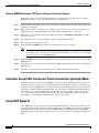
Configuring the System for SpectraLink NetLink Telephones 3-11
Using the Controller CLI to Enable Long Preambles 3-12
Using the Controller GUI to Enable Long Preambles 3-13
Using WCS to Enable Long Preambles 3-13
Using Management over Wireless 3-14
Using the Controller CLI to Enable Management over Wireless 3-14
Using the the Controller GUI to Enable Management over Wireless 3-15
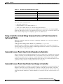
Configuring DHCP 3-15
Using the Controller CLI to Configure DHCP 3-15
Using the Controller GUI to Configure DHCP 3-16
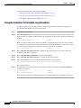
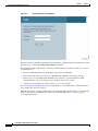
Customizing the Web Auth Login Screen 3-16
Default Web Auth Operation 3-17
Customizing Web Auth Operation 3-19
Hiding and Restoring the Cisco WLAN Solution Logo 3-19
Changing the Web Auth Window Title 3-19
Changing the Web Message 3-20
Changing the Logo 3-20
Creating a Custom URL Redirect 3-21
Verifying your Web Auth Changes 3-22
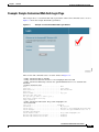
Example: Sample Customized Web Auth Login Page 3-23
Configuring Identity Networking 3-24
Identity Networking Overview 3-24
RADIUS Attributes Used in Identity Networking
QoS-Level 3-25
ACL-Name 3-25
Interface-Name 3-26
VLAN-Tag 3-26
Tunnel Attributes 3-27
CHAPTER
4
Configuring Controller Settings
3-25
4-1
Using the Configuration Wizard 4-2
Before You Start 4-2
Resetting the Device to Default Settings
4-3
Cisco Wireless LAN Solution Product Guide
OL-7955-01
vii
Contents
Resetting to Default Settings Using the CLI 4-3
Resetting to Default Settings Using the GUI 4-3
Running the Configuration Wizard on the CLI 4-4
Managing the System Time and Date 4-5
Configuring Time and Date Manually 4-5
Configuring NTP 4-5
Configuring a Country Code
4-5
Enabling and Disabling 802.11 Bands
4-6
Configuring Administrator Usernames and Passwords
Configuring RADIUS Settings
4-7
Configuring SNMP Settings
4-7
Configuring Mobility Groups
4-8
Configuring RADIUS Settings
Configuring the Service Port
4-9
4-9
Configuring Radio Resource Management (RRM)
Configuring the Serial (CLI Console) Port
Enabling 802.3x Flow Control
Enabling System Logging
5
Configuring Wireless LANs
Wireless LAN Overview
4-9
4-10
4-10
4-10
Enabling Dynamic Transmit Power Control
CHAPTER
4-7
4-10
5-1
5-2
Configuring Wireless LANs 5-2
Displaying, Creating, Disabling, and Deleting Wireless LANs
Activating Wireless LANs 5-3
Assigning a Wireless LAN to a DHCP Server 5-3
Configuring MAC Filtering for Wireless LANs 5-3
Enabling MAC Filtering 5-3
Creating a Local MAC Filter 5-3
Configuring a Timeout for Disabled Clients 5-4
Assigning Wireless LANs to VLANs 5-4
Configuring Layer 2 Security 5-4
Dynamic 802.1X Keys and Authorization 5-4
WEP Keys 5-5
Dynamic WPA Keys and Encryption 5-5
Configuring Layer 3 Security 5-6
IPSec 5-6
IPSec Authentication 5-6
5-2
Cisco Wireless LAN Solution Product Guide
viii
OL-7955-01
Contents
IPSec Encryption 5-6
IKE Authentication 5-6
IKE Diffie-Hellman Group 5-7
IKE Phase 1 Aggressive and Main Modes 5-7
IKE Lifetime Timeout 5-7
IPSec Passthrough 5-7
Web-Based Authentication 5-7
Local Netuser 5-8
Configuring Quality of Service 5-8
Configuring QoS Enhanced BSS (QBSS) 5-8
Configuring Auto Anchoring 5-9
Guidelines for Using Auto Anchoring 5-9
Adding Anchors for a Wireless LAN 5-10
Deleting Anchors for a Wireless LAN and Disabling Auto Anchoring
Displaying Auto Anchor Controllers 5-10
CHAPTER
6
Managing Controller Software
and Configurations 6-1
Transferring Files to and from a Controller
Upgrading Controller Software
Saving Configurations
6-4
6-4
Erasing the Controller Configuration
Resetting the Controller
7
6-2
6-2
Clearing the Controller Configuration
CHAPTER
6-4
6-5
Configuring Management Interfaces and Ports
Overview of Interfaces and Ports
7-1
7-2
Verifying and Changing the Management Interfaces
Creating and Assigning the AP-Manager Interface
7-2
7-3
Creating, Assigning, and Deleting Operator-Defined Interfaces
Verifying and Changing the Virtual Interface
Enabling Web and Secure Web Modes
Configuring Spanning Tree Protocol
CHAPTER
8
5-10
Starting and Stopping WCS
7-3
7-4
7-5
7-5
8-1
Starting and Stopping Cisco WCS for Windows 8-2
Starting Cisco WCS as a Windows Application 8-2
Starting Cisco WCS as a Windows Service 8-2
Cisco Wireless LAN Solution Product Guide
OL-7955-01
ix
Contents
Stopping the Cisco WCS Application for Windows 8-3
Stopping the Cisco WCS Service for Windows 8-3
Checking the Cisco WCS for Windows Service Status 8-3
Starting and Stopping Cisco WCS for Linux 8-4
Starting the Cisco WCS for Linux Application 8-4
Stopping the Cisco WCS for Linux Application 8-4
Checking the Cisco WCS for Linux Status 8-5
Starting and Stopping the Cisco WCS Web Interface 8-5
Starting a Cisco WCS User Interface 8-5
Stopping a Cisco WCS User Interface 8-6
User Interface Session Stops When Cisco WCS is Shut Down
CHAPTER
9
Using Cisco WCS
8-6
9-1
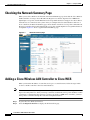
Checking the Network Summary Page
9-2
Adding a Cisco Wireless LAN Controller to Cisco WCS
Creating an RF Calibration Model
9-2
9-3
Using Maps 9-4
Adding a Campus Map to the Cisco WCS Database 9-4
Adding a Building to a Campus 9-5
Adding a Standalone Building to the Cisco WCS Database 9-5
Adding an Outdoor Area to a Campus 9-6
Adding Floor Plans to a Campus Building 9-7
Using the Map Editor 9-8
Adding Floor Plans to a Standalone Building 9-8
Adding Access Points to Floor Plan and Outdoor Area Maps 9-9
Monitoring Maps 9-11
Monitoring Predicted Coverage (RSSI) 9-11
Monitoring Channels on a Floor Map 9-12
Monitoring Transmit Power Levels on a Floor Map 9-13
Monitoring Coverage Holes on a Floor Map 9-13
Monitoring Users on a Floor Map 9-14
Monitoring WLANs with Cisco WCS 9-14
Detecting and Locating Rogue Access Points 9-14
Acknowledging Rogue Access Points 9-16
Locating Clients 9-16
Finding Coverage Holes 9-18
Pinging a Network Device from a Controller 9-18
Viewing Current Controller Status and Configurations
Viewing Cisco WCS Statistics Reports 9-19
9-18
Cisco Wireless LAN Solution Product Guide
x
OL-7955-01
Contents
Using Cisco WCS to Update System Software
9-19
Managing Cisco WCS and the Cisco WCS Database 9-20
Installing Cisco WCS 9-20
Updating the Cisco WCS for Windows 9-20
Updating Cisco WCS for Linux 9-21
Reinitializing the Cisco WCS for Windows Database 9-22
Reinitializing the Cisco WCS for Linux Database 9-23
Administering Cisco WCS Users and Passwords 9-23
Adding WCS User Accounts 9-24
Changing Passwords 9-24
Deleting User Accounts 9-25
CHAPTER
10
Configuring and Using Location Appliances
10-1
Configuring Location Appliances 10-2
Adding a Location Appliance to the Cisco WCS Database 10-2
Editing a Contact, User Name, Password, and HTTP/HTTPS Selection 10-3
Synchronizing Location Appliance and Cisco WCS Network Designs 10-3
Synchronizing Controllers and Location Appliances 10-4
Assigning Location Appliances to Controllers 10-4
Unassigning Location Appliances to Controllers 10-4
Editing Location Appliance Polling Parameters 10-5
Editing Location Appliance History Parameters 10-6
Editing Location Appliance Location Parameters 10-7
Managing Location Appliance User Groups 10-7
Adding Location Appliance User Groups 10-7
Changing Location Appliance User Group Permissions 10-8
Deleting Location Appliance User Groups 10-8
Adding Location Appliance Users 10-8
Changing Location Appliance User Passwords, Group Names, and Permissions
Deleting Location Appliance Users 10-9
Adding Location Appliance Host Access 10-9
Deleting Location Appliance Host Access 10-10
Editing Location Appliance Advanced Parameters 10-10
Clearing Location Appliance Configurations 10-11
Deleting a Location Appliance from the Cisco WCS Database 10-11
Operating Location Appliances 10-12
Managing Location Appliance Alarms and Events 10-12
Viewing Location Appliance Alarms 10-12
Assigning and Unassigning Location Appliance Alarms
10-9
10-12
Cisco Wireless LAN Solution Product Guide
OL-7955-01
xi
Contents
Deleting and Clearing Location Appliance Alarms 10-13
Viewing Location Appliance Alarm Events 10-13
Viewing Location Appliance Events 10-13
Backing Up Location Appliance Historical Data 10-14
Restoring Location Appliance Historical Data 10-14
Viewing Controller and Location Appliance Synchronization Status 10-15
Re-Synchronizing Controller and Location Appliance Databases 10-15
Viewing Location Appliance Current Status 10-15
Downloading Location Appliance Log Files to Your Cisco WCS Terminal 10-16
Downloading Application Code to a Location Appliance using Cisco WCS 10-16
Defragmenting the Location Appliance Database 10-17
Running Java GC on the Location Appliance Memory 10-17
Restarting the Location Appliance Application Software 10-18
Rebooting the Location Appliance 10-18
APPENDIX
A
Safety Considerations and
Translated Safety Warnings
Safety Considerations
Warning Definition
A-1
A-2
A-2
Class 1 Laser Product Warning
Ground Conductor Warning
A-5
A-7
Chassis Warning for Rack-Mounting and Servicing
Battery Handling Warning for 4400 Series Controllers
Equipment Installation Warning
A-9
A-18
A-20
More Than One Power Supply Warning for 4400 Series Controllers
APPENDIX
B
Declarations of Conformity and Regulatory Information
A-23
B-1
Regulatory Information for 1000 Series Access Points B-2
Manufacturers Federal Communication Commission Declaration of Conformity Statement
Department of Communications—Canada B-3
Canadian Compliance Statement B-3
European Community, Switzerland, Norway, Iceland, and Liechtenstein B-4
Declaration of Conformity with Regard to the R&TTE Directive 1999/5/EC B-4
Declaration of Conformity for RF Exposure B-5
Guidelines for Operating Cisco Aironet Access Points in Japan B-5
Administrative Rules for Cisco Aironet Access Points in Taiwan B-6
Access Points with IEEE 802.11a Radios B-6
All Access Points B-7
Declaration of Conformity Statements B-8
B-2
Cisco Wireless LAN Solution Product Guide
xii
OL-7955-01
Contents
FCC Statements for Cisco 2000 Series Wireless LAN Controllers
B-9
FCC Statements for Cisco 4100 Series Wireless LAN Controllers and Cisco 4400 Series Wireless LAN
Controllers B-10
APPENDIX
C
End User License and Warranty
End User License Agreement
Limited Warranty C-4
Disclaimer of Warranty
C-1
C-2
C-6
General Terms Applicable to the Limited Warranty Statement and End User License Agreement
Additional Open Source Terms
C-7
APPENDIX
D
Cisco WLAN Solution Supported Country Codes
D-1
APPENDIX
E
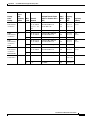
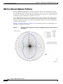
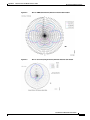
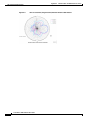
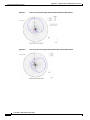
Antenna Patterns for 1000 Series Access Points
E-1
802.11a Internal Antenna Patterns
802.11b/g Internal Antenna Patterns
APPENDIX
F
C-6
E-2
E-5
System Messages and Access Point
LED Patterns F-1
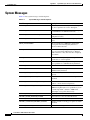
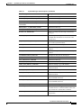
System Messages
F-2
Using Client Reason and Status Codes in Trap Logs
Client Reason Codes F-4
Client Status Codes F-5
Using Lightweight Access Point LEDs
F-4
F-6
INDEX
Cisco Wireless LAN Solution Product Guide
OL-7955-01
xiii
Contents
Cisco Wireless LAN Solution Product Guide
xiv
OL-7955-01
Preface
Audience
This guide describes these Cisco Wireless LAN Solution (Cisco WLAN Solution) products:
•
The Cisco Wireless Control System (WCS)
•
Cisco Wireless LAN Controllers
•
Cisco Wireless Location Appliances
•
Cisco Lightweight Access Points
This guide is for the networking professional who installs and manages these devices. To use this guide,
you should be familiar with the concepts and terminology of wireless LANs.
Purpose
This guide provides the information you need to set up and configure a wireless LAN solution using
WCS, WLAN controllers, location appliances, and lightweight access points.
Organization
This guide is organized into these chapters:
Chapter 1, “Overview,” provides an overview of Cisco WLAN Solution products and features.
Chapter 2, “Using the Web-Browser and CLI Interfaces,” describes how to use the GUI and CLI for the
WCS and controllers.
Chapter 3, “Solutions,” describes application-specific solutions for wireless LANs.
Chapter 5, “Configuring Wireless LANs,” describes how to configure the wireless LANs on your
system.
Chapter 6, “Managing Controller Software and Configurations,” describes how to manage the software
and configurations on controllers.
Chapter 7, “Configuring Management Interfaces and Ports,” describes how to configure the management
interfaces and ports on controllers.
Chapter 8, “Starting and Stopping WCS,” describes how to start and stop the WCS application and
server.
Cisco Wireless LAN Solution Product Guide
OL-7955-01
xv
Preface
Conventions
Chapter 9, “Using Cisco WCS,” explains how to use WCS to control your WLAN solution.
Chapter 10, “Configuring and Using Location Appliances,” describes how to configure and use location
appliances on your WLAN.
Appendix A, “Safety Considerations and Translated Safety Warnings”
Appendix B, “Declarations of Conformity and Regulatory Information”
Appendix C, “End User License and Warranty”
Appendix D, “Cisco WLAN Solution Supported Country Codes”
Appendix E, “Antenna Patterns for 1000 Series Access Points”
Appendix F, “System Messages and Access Point LED Patterns”
Conventions
This publication uses these conventions to convey instructions and information:
Command descriptions use these conventions:
•
Commands and keywords are in boldface text.
•
Arguments for which you supply values are in italic.
•
Square brackets ([ ]) mean optional elements.
•
Braces ({ }) group required choices, and vertical bars ( | ) separate the alternative elements.
•
Braces and vertical bars within square brackets ([{ | }]) mean a required choice within an optional
element.
Interactive examples use these conventions:
•
Terminal sessions and system displays are in screen font.
•
Information you enter is in boldface screen font.
•
Nonprinting characters, such as passwords or tabs, are in angle brackets (< >).
Notes, cautions, and timesavers use these conventions and symbols:
Tip
Means the following will help you solve a problem. The tips information might not be troubleshooting
or even an action, but could be useful information.
Note
Means reader take note. Notes contain helpful suggestions or references to materials not contained in
this manual.
Caution
Means reader be careful. In this situation, you might do something that could result equipment damage
or loss of data.
Cisco Wireless LAN Solution Product Guide
xvi
OL-7955-01
Preface
Conventions
Warning
Waarschuwing
This warning symbol means danger. You are in a situation that could cause bodily injury. Before you
work on any equipment, be aware of the hazards involved with electrical circuitry and be familiar
with standard practices for preventing accidents. (To see translations of the warnings that appear
in this publication, refer to the appendix “Translated Safety Warnings.”)
Dit waarschuwingssymbool betekent gevaar. U verkeert in een situatie die lichamelijk letsel kan
veroorzaken. Voordat u aan enige apparatuur gaat werken, dient u zich bewust te zijn van de bij
elektrische schakelingen betrokken risico’s en dient u op de hoogte te zijn van standaard
maatregelen om ongelukken te voorkomen. (Voor vertalingen van de waarschuwingen die in deze
publicatie verschijnen, kunt u het aanhangsel “Translated Safety Warnings” (Vertalingen van
veiligheidsvoorschriften) raadplegen.)
Varoitus
Tämä varoitusmerkki merkitsee vaaraa. Olet tilanteessa, joka voi johtaa ruumiinvammaan. Ennen
kuin työskentelet minkään laitteiston parissa, ota selvää sähkökytkentöihin liittyvistä vaaroista ja
tavanomaisista onnettomuuksien ehkäisykeinoista. (Tässä julkaisussa esiintyvien varoitusten
käännökset löydät liitteestä "Translated Safety Warnings" (käännetyt turvallisuutta koskevat
varoitukset).)
Attention
Ce symbole d’avertissement indique un danger. Vous vous trouvez dans une situation pouvant
entraîner des blessures. Avant d’accéder à cet équipement, soyez conscient des dangers posés par
les circuits électriques et familiarisez-vous avec les procédures courantes de prévention des
accidents. Pour obtenir les traductions des mises en garde figurant dans cette publication, veuillez
consulter l’annexe intitulée « Translated Safety Warnings » (Traduction des avis de sécurité).
Warnung
Dieses Warnsymbol bedeutet Gefahr. Sie befinden sich in einer Situation, die zu einer
Körperverletzung führen könnte. Bevor Sie mit der Arbeit an irgendeinem Gerät beginnen, seien Sie
sich der mit elektrischen Stromkreisen verbundenen Gefahren und der Standardpraktiken zur
Vermeidung von Unfällen bewußt. (Übersetzungen der in dieser Veröffentlichung enthaltenen
Warnhinweise finden Sie im Anhang mit dem Titel “Translated Safety Warnings” (Übersetzung der
Warnhinweise).)
Avvertenza
Questo simbolo di avvertenza indica un pericolo. Si è in una situazione che può causare infortuni.
Prima di lavorare su qualsiasi apparecchiatura, occorre conoscere i pericoli relativi ai circuiti
elettrici ed essere al corrente delle pratiche standard per la prevenzione di incidenti. La traduzione
delle avvertenze riportate in questa pubblicazione si trova nell’appendice, “Translated Safety
Warnings” (Traduzione delle avvertenze di sicurezza).
Advarsel
Dette varselsymbolet betyr fare. Du befinner deg i en situasjon som kan føre til personskade. Før du
utfører arbeid på utstyr, må du være oppmerksom på de faremomentene som elektriske kretser
innebærer, samt gjøre deg kjent med vanlig praksis når det gjelder å unngå ulykker. (Hvis du vil se
oversettelser av de advarslene som finnes i denne publikasjonen, kan du se i vedlegget "Translated
Safety Warnings" [Oversatte sikkerhetsadvarsler].)
Aviso
Este símbolo de aviso indica perigo. Encontra-se numa situação que lhe poderá causar danos
fisicos. Antes de começar a trabalhar com qualquer equipamento, familiarize-se com os perigos
relacionados com circuitos eléctricos, e com quaisquer práticas comuns que possam prevenir
possíveis acidentes. (Para ver as traduções dos avisos que constam desta publicação, consulte o
apêndice “Translated Safety Warnings” - “Traduções dos Avisos de Segurança”).
Cisco Wireless LAN Solution Product Guide
OL-7955-01
xvii
Preface
Related Publications
¡Advertencia!
Este símbolo de aviso significa peligro. Existe riesgo para su integridad física. Antes de manipular
cualquier equipo, considerar los riesgos que entraña la corriente eléctrica y familiarizarse con los
procedimientos estándar de prevención de accidentes. (Para ver traducciones de las advertencias
que aparecen en esta publicación, consultar el apéndice titulado “Translated Safety Warnings.”)
Varning!
Denna varningssymbol signalerar fara. Du befinner dig i en situation som kan leda till personskada.
Innan du utför arbete på någon utrustning måste du vara medveten om farorna med elkretsar och
känna till vanligt förfarande för att förebygga skador. (Se förklaringar av de varningar som
förekommer i denna publikation i appendix "Translated Safety Warnings" [Översatta
säkerhetsvarningar].)
Related Publications
These documents provide complete information about the Cisco Wireless LAN Solution:
•
Cisco WLAN Solution CLI Reference
•
Cisco 1000 Series IEEE 802.11a/b/g Lightweight Access Point Deployment Guide
•
Internal-Antenna AP1010 Cisco 1000 Series IEEE 802.11a/b/g Lightweight Access Point Quick
Start Guide
•
External-Antenna AP1020 and AP1030 Cisco 1000 Series IEEE 802.11a/b/g Lightweight Access
Point Quick Start Guide
•
Cisco 1000 Series IEEE 802.11a/b/g Lightweight Access Point Ceiling-Mount Bezel Kit Quick Start
Guide
•
Cisco 2000 Series Wireless LAN Controller Quick Start Guide
•
Cisco 2700 Series Location Appliance Quick Start Guide
•
Cisco 4100 Series Wireless LAN Controller Quick Start Guide
•
Cisco 4400 Series Wireless LAN Controller Quick Start Guide
•
VPN/Enhanced Security Module Quick Start Guide
•
1000BASE-SX, 1000BASE-LX, and 1000BASE-T SFP Modules Quick Start Guide
•
Cisco 4400 Series Power Supply Quick Start Guide
•
Cisco WCS for Windows Quick Start Guide
•
Cisco WCS for Linux Quick Start Guide
•
Cisco Wireless LAN Controller and Cisco 1000 Series Lightweight Access Point Release Notes
•
Cisco 2700 Series Location Appliance Release Notes
•
Cisco WCS for Windows Release Notes
•
Cisco WCS for Linux Release Notes
Click this link to browse to user documentation for the Cisco Wireless LAN Solution:
http://www.cisco.com/en/US/products/hw/wireless/tsd_products_support_category_home.html
Cisco Wireless LAN Solution Product Guide
xviii
OL-7955-01
Preface
Obtaining Documentation
Obtaining Documentation
Cisco documentation and additional literature are available on Cisco.com. Cisco also provides several
ways to obtain technical assistance and other technical resources. These sections explain how to obtain
technical information from Cisco Systems.
Cisco.com
You can access the most current Cisco documentation at this URL:
http://www.cisco.com/techsupport
You can access the Cisco website at this URL:
http://www.cisco.com
You can access international Cisco websites at this URL:
http://www.cisco.com/public/countries_languages.shtml
Product Documentation DVD
Cisco documentation and additional literature are available in the Product Documentation DVD package,
which may have shipped with your product. The Product Documentation DVD is updated regularly and
may be more current than printed documentation.
The Product Documentation DVD is a comprehensive library of technical product documentation on
portable media. The DVD enables you to access multiple versions of hardware and software installation,
configuration, and command guides for Cisco products and to view technical documentation in HTML.
With the DVD, you have access to the same documentation that is found on the Cisco website without
being connected to the Internet. Certain products also have .pdf versions of the documentation available.
The Product Documentation DVD is available as a single unit or as a subscription. Registered Cisco.com
users (Cisco direct customers) can order a Product Documentation DVD (product number
DOC-DOCDVD=) from Cisco Marketplace at this URL:
http://www.cisco.com/go/marketplace/
Ordering Documentation
Beginning June 30, 2005, registered Cisco.com users may order Cisco documentation at the Product
Documentation Store in the Cisco Marketplace at this URL:
http://www.cisco.com/go/marketplace/
Nonregistered Cisco.com users can order technical documentation from 8:00 a.m. to 5:00 p.m.
(0800 to 1700) PDT by calling 1 866 463-3487 in the United States and Canada, or elsewhere by
calling 011 408 519-5055. You can also order documentation by e-mail at
[email protected] or by fax at 1 408 519-5001 in the United States and Canada,
or elsewhere at 011 408 519-5001.
Cisco Wireless LAN Solution Product Guide
OL-7955-01
xix
Preface
Documentation Feedback
Documentation Feedback
You can rate and provide feedback about Cisco technical documents by completing the online feedback
form that appears with the technical documents on Cisco.com.
You can send comments about Cisco documentation to [email protected].
You can submit comments by using the response card (if present) behind the front cover of your
document or by writing to the following address:
Cisco Systems
Attn: Customer Document Ordering
170 West Tasman Drive
San Jose, CA 95134-9883
We appreciate your comments.
Cisco Product Security Overview
Cisco provides a free online Security Vulnerability Policy portal at this URL:
http://www.cisco.com/en/US/products/products_security_vulnerability_policy.html
From this site, you can perform these tasks:
•
Report security vulnerabilities in Cisco products.
•
Obtain assistance with security incidents that involve Cisco products.
•
Register to receive security information from Cisco.
A current list of security advisories and notices for Cisco products is available at this URL:
http://www.cisco.com/go/psirt
If you prefer to see advisories and notices as they are updated in real time, you can access a Product
Security Incident Response Team Really Simple Syndication (PSIRT RSS) feed from this URL:
http://www.cisco.com/en/US/products/products_psirt_rss_feed.html
Reporting Security Problems in Cisco Products
Cisco is committed to delivering secure products. We test our products internally before we release them,
and we strive to correct all vulnerabilities quickly. If you think that you might have identified a
vulnerability in a Cisco product, contact PSIRT:
•
Emergencies — [email protected]
An emergency is either a condition in which a system is under active attack or a condition for which
a severe and urgent security vulnerability should be reported. All other conditions are considered
nonemergencies.
•
Nonemergencies — [email protected]
In an emergency, you can also reach PSIRT by telephone:
•
1 877 228-7302
•
1 408 525-6532
Cisco Wireless LAN Solution Product Guide
xx
OL-7955-01
Preface
Obtaining Technical Assistance
Tip
We encourage you to use Pretty Good Privacy (PGP) or a compatible product to encrypt any sensitive
information that you send to Cisco. PSIRT can work from encrypted information that is compatible with
PGP versions 2.x through 8.x.
Never use a revoked or an expired encryption key. The correct public key to use in your correspondence
with PSIRT is the one linked in the Contact Summary section of the Security Vulnerability Policy page
at this URL:
http://www.cisco.com/en/US/products/products_security_vulnerability_policy.html
The link on this page has the current PGP key ID in use.
Obtaining Technical Assistance
Cisco Technical Support provides 24-hour-a-day award-winning technical assistance. The Cisco
Technical Support & Documentation website on Cisco.com features extensive online support resources.
In addition, if you have a valid Cisco service contract, Cisco Technical Assistance Center (TAC)
engineers provide telephone support. If you do not have a valid Cisco service contract, contact your
reseller.
Cisco Technical Support & Documentation Website
The Cisco Technical Support & Documentation website provides online documents and tools for
troubleshooting and resolving technical issues with Cisco products and technologies. The website is
available 24 hours a day, at this URL:
http://www.cisco.com/techsupport
Access to all tools on the Cisco Technical Support & Documentation website requires a Cisco.com user
ID and password. If you have a valid service contract but do not have a user ID or password, you can
register at this URL:
http://tools.cisco.com/RPF/register/register.do
Note
Use the Cisco Product Identification (CPI) tool to locate your product serial number before submitting
a web or phone request for service. You can access the CPI tool from the Cisco Technical Support &
Documentation website by clicking the Tools & Resources link under Documentation & Tools. Choose
Cisco Product Identification Tool from the Alphabetical Index drop-down list, or click the Cisco
Product Identification Tool link under Alerts & RMAs. The CPI tool offers three search options: by
product ID or model name; by tree view; or for certain products, by copying and pasting show command
output. Search results show an illustration of your product with the serial number label location
highlighted. Locate the serial number label on your product and record the information before placing a
service call.
Cisco Wireless LAN Solution Product Guide
OL-7955-01
xxi
Preface
Obtaining Additional Publications and Information
Submitting a Service Request
Using the online TAC Service Request Tool is the fastest way to open S3 and S4 service requests. (S3
and S4 service requests are those in which your network is minimally impaired or for which you require
product information.) After you describe your situation, the TAC Service Request Tool provides
recommended solutions. If your issue is not resolved using the recommended resources, your service
request is assigned to a Cisco engineer. The TAC Service Request Tool is located at this URL:
http://www.cisco.com/techsupport/servicerequest
For S1 or S2 service requests or if you do not have Internet access, contact the Cisco TAC by telephone.
(S1 or S2 service requests are those in which your production network is down or severely degraded.)
Cisco engineers are assigned immediately to S1 and S2 service requests to help keep your business
operations running smoothly.
To open a service request by telephone, use one of the following numbers:
Asia-Pacific: +61 2 8446 7411 (Australia: 1 800 805 227)
EMEA: +32 2 704 55 55
USA: 1 800 553-2447
For a complete list of Cisco TAC contacts, go to this URL:
http://www.cisco.com/techsupport/contacts
Definitions of Service Request Severity
To ensure that all service requests are reported in a standard format, Cisco has established severity
definitions.
Severity 1 (S1)—Your network is “down,” or there is a critical impact to your business operations. You
and Cisco will commit all necessary resources around the clock to resolve the situation.
Severity 2 (S2)—Operation of an existing network is severely degraded, or significant aspects of your
business operation are negatively affected by inadequate performance of Cisco products. You and Cisco
will commit full-time resources during normal business hours to resolve the situation.
Severity 3 (S3)—Operational performance of your network is impaired, but most business operations
remain functional. You and Cisco will commit resources during normal business hours to restore service
to satisfactory levels.
Severity 4 (S4)—You require information or assistance with Cisco product capabilities, installation, or
configuration. There is little or no effect on your business operations.
Obtaining Additional Publications and Information
Information about Cisco products, technologies, and network solutions is available from various online
and printed sources.
•
Cisco Marketplace provides a variety of Cisco books, reference guides, documentation, and logo
merchandise. Visit Cisco Marketplace, the company store, at this URL:
http://www.cisco.com/go/marketplace/
Cisco Wireless LAN Solution Product Guide
xxii
OL-7955-01
Preface
Obtaining Additional Publications and Information
•
Cisco Press publishes a wide range of general networking, training and certification titles. Both new
and experienced users will benefit from these publications. For current Cisco Press titles and other
information, go to Cisco Press at this URL:
http://www.ciscopress.com
•
Packet magazine is the Cisco Systems technical user magazine for maximizing Internet and
networking investments. Each quarter, Packet delivers coverage of the latest industry trends,
technology breakthroughs, and Cisco products and solutions, as well as network deployment and
troubleshooting tips, configuration examples, customer case studies, certification and training
information, and links to scores of in-depth online resources. You can access Packet magazine at
this URL:
http://www.cisco.com/packet
•
iQ Magazine is the quarterly publication from Cisco Systems designed to help growing companies
learn how they can use technology to increase revenue, streamline their business, and expand
services. The publication identifies the challenges facing these companies and the technologies to
help solve them, using real-world case studies and business strategies to help readers make sound
technology investment decisions. You can access iQ Magazine at this URL:
http://www.cisco.com/go/iqmagazine
or view the digital edition at this URL:
http://ciscoiq.texterity.com/ciscoiq/sample/
•
Internet Protocol Journal is a quarterly journal published by Cisco Systems for engineering
professionals involved in designing, developing, and operating public and private internets and
intranets. You can access the Internet Protocol Journal at this URL:
http://www.cisco.com/ipj
•
Networking products offered by Cisco Systems, as well as customer support services, can be
obtained at this URL:
http://www.cisco.com/en/US/products/index.html
•
Networking Professionals Connection is an interactive website for networking professionals to share
questions, suggestions, and information about networking products and technologies with Cisco
experts and other networking professionals. Join a discussion at this URL:
http://www.cisco.com/discuss/networking
•
World-class networking training is available from Cisco. You can view current offerings at
this URL:
http://www.cisco.com/en/US/learning/index.html
Cisco Wireless LAN Solution Product Guide
OL-7955-01
xxiii
Preface
Obtaining Additional Publications and Information
Cisco Wireless LAN Solution Product Guide
xxiv
OL-7955-01
C H A P T E R
1
Overview
This chapter describes the components and features of the Cisco Wireless LAN Solution. This chapter
contains these sections:
•
Cisco Wireless LAN Solution Overview, page 1-2
•
Operating System Software, page 1-5
•
Operating System Security, page 1-5
•
Radio Resource Management (RRM), page 1-7
•
Cisco Wireless LAN Controllers, page 1-8
•
Client Roaming, page 1-9
•
External DHCP Servers, page 1-11
•
Cisco WLAN Solution Mobility Groups, page 1-12
•
Cisco WLAN Solution Wired Connections, page 1-13
•
Cisco WLAN Solution Wireless LANs, page 1-14
•
Access Control Lists, page 1-14
•
Identity Networking, page 1-15
•
Dynamic Frequency Selection, page 1-16
•
File Transfers, page 1-17
•
Power over Ethernet, page 1-17
•
Pico Cell Functionality, page 1-18
•
Intrusion Detection Service (IDS), page 1-18
•
Cisco Wireless LAN Controllers, page 1-19
•
Lightweight Access Points, page 1-32
•
Autonomous Access Points Converted to Lightweight Mode, page 1-38
•
Rogue Access Points, page 1-43
•
Web User Interface and the CLI, page 1-44
•
Cisco Wireless Control System, page 1-45
•
Cisco 2700 Series Location Appliances, page 1-49
Cisco Wireless LAN Solution Product Guide
OL-7955-01
1-1
Chapter 1
Overview
Cisco Wireless LAN Solution Overview
Cisco Wireless LAN Solution Overview
The Cisco Wireless LAN Solution is designed to provide 802.11 wireless networking solutions for
enterprises and service providers. The Cisco Wireless LAN Solution simplifies deploying and managing
large-scale wireless LANs and enables a unique best-in-class security infrastructure. The operating
system manages all data client, communications, and system administration functions, performs Radio
Resource Management (RRM) functions, manages system-wide mobility policies using the operating
system Security solution, and coordinates all security functions using the operating system security
framework.
The Cisco Wireless LAN Solution consists of Cisco Wireless LAN Controllers and their associated
lightweight access points controlled by the operating system, all concurrently managed by any or all of
the operating system user interfaces:
•
An HTTP and/or HTTPS full-featured Web User Interface hosted by Cisco Wireless LAN
Controllers can be used to configure and monitor individual controllers. See the “Web User Interface
and the CLI” section on page 1-44.
•
A full-featured command-line interface (CLI) can be used to configure and monitor individual Cisco
Wireless LAN Controllers. See the “Web User Interface and the CLI” section on page 1-44.
•
The “Cisco Wireless Control System” section on page 1-45 describes the Cisco Wireless Control
System (WCS), which you use to configure and monitor one or more Cisco Wireless LAN
Controllers and associated access points. WCS has tools to facilitate large-system monitoring and
control. WCS runs on Windows 2000, Windows 2003, and Red Hat Enterprise Linux ES servers.
•
An industry-standard SNMP V1, V2c, and V3 interface can be used with any SNMP-compliant
third-party network management system.
The Cisco Wireless LAN Solution supports client data services, client monitoring and control, and all
rogue access point detection, monitoring, and containment functions. The Cisco Wireless LAN Solution
uses lightweight access points, Cisco Wireless LAN Controllers, and the optional Cisco WCS to provide
wireless services to enterprises and service providers.
The Cisco WCS application is offered in two versions:
•
Cisco WCS Base, which also supports client, rogue access point, rogue access point client, radio
frequency ID (RFID) tag location to the nearest lightweight access point.
•
Cisco WCS Location, which also supports client, rogue access point, rogue access point client,
RFID tag location to within 10 meters.
See the “Cisco WCS Base” section on page 1-46 and the “Cisco WCS Location” section on page 1-47
for more information.
When Cisco WCS Location is used, Cisco Wireless LAN Solution end users can also deploy Cisco 2700
Series Location Appliances, described in Chapter 10, “Configuring and Using Location Appliances.”
The location appliance enhances the high-accuracy built-in Cisco WCS Location abilities by computing,
collecting and storing historical location data, which can be displayed in Cisco WCS. In this role, the
location appliance acts as a server to one or more Cisco WCS Servers, collecting, storing, and passing
on data from its associated controllers.
Note
1-2
This document refers to Cisco Wireless LAN Controllers throughout. Unless specifically called out, the
descriptions herein apply to all Cisco Wireless LAN Controllers, including but not limited to Cisco 2000
Series Wireless LAN Controllers, Cisco 4100 Series Wireless LAN Controllers, and Cisco 4400 Series
Wireless LAN Controllers.
Cisco Wireless LAN Solution Product Guide
OL-7955-01
Chapter 1
Overview
Cisco Wireless LAN Solution Overview
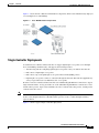
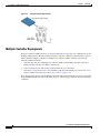
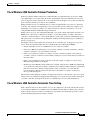
Figure 1-1 shows the Cisco Wireless LAN Solution components, which can be simultaneously deployed
across multiple floors and buildings.
Figure 1-1
Cisco WLAN Solution Components
Single-Controller Deployments
A standalone Cisco Wireless LAN Controller can support lightweight access points across multiple
floors and buildings simultaneously, and supports the following features:
•
Autodetecting and autoconfiguring lightweight access points as they are added to the network.
•
Full control of lightweight access points.
•
Full control of up to 16 lightweight access point wireless LAN (SSID) policies.
•
Lightweight access points connect to controllers through the network. The network equipment may
or may not provide Power over Ethernet to the access points.
Note that some Cisco Wireless LAN Controllers use redundant Gigabit Ethernet connections to bypass
single network failures. At any given time one of the redundant Gigabit Ethernet connections is active
and the other is passive. Upon a network failure, the active connection becomes passive, and the passive
connection becomes active.
Note
Some controllers can connect through multiple physical ports to multiple subnets in the network. This
feature can be helpful when Cisco WLAN Solution operators want to confine multiple VLANs to
separate subnets.
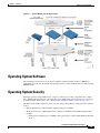
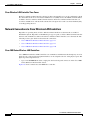
Figure 1-2 shows a typical single-controller deployment.
Cisco Wireless LAN Solution Product Guide
OL-7955-01
1-3
Chapter 1
Overview
Cisco Wireless LAN Solution Overview
Figure 1-2
Single-Controller Deployment
Multiple-Controller Deployments
Each Cisco Wireless LAN Controller can support lightweight access points across multiple floors and
buildings simultaneously. However, full functionality of the Cisco Wireless LAN Solution is realized
when it includes multiple controllers. A multiple-Cisco Wireless LAN Controller system has the
following additional features:
•
Autodetecting and autoconfiguring Cisco Wireless LAN Controller RF parameters as the Cisco
Wireless LAN Controllers are added to the network.
•
Same-Controller (Layer 2) Roaming and Inter-Subnet (Layer 3) Roaming.
•
Automatic access point failover to any redundant controller with unused ports (refer to the “Cisco
Wireless LAN Controller Failover Protection” section on page 1-27).
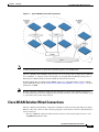
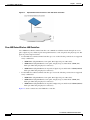
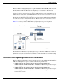
The following figure shows a typical multiple-controller deployment. The figure also shows an optional
dedicated Management Network and the three physical connection types between the network and the
controllers.
1-4
Cisco Wireless LAN Solution Product Guide
OL-7955-01
Chapter 1
Overview
Operating System Software
Figure 1-3
Typical Multi-Controller Deployment
Operating System Software
The Operating System Software controls Cisco Wireless LAN Controllers and Cisco 1000 Series
Lightweight Access Points. It includes full operating system security and Radio Resource Management
(RRM) features.
Operating System Security
Operating system security bundles Layer 1, Layer 2, and Layer 3 security components into a simple,
Cisco WLAN Solution-wide policy manager that creates independent security policies for each of up to
16 wireless LANs. (Refer to the “Cisco WLAN Solution Wireless LANs” section on page 1-14.)
The 802.11 Static WEP weaknesses can be overcome using robust industry-standard security solutions,
such as:
•
802.1X dynamic keys with extensible authentication protocol (EAP).
•
Wi-Fi protected access (WPA) dynamic keys. The Cisco WLAN Solution WPA implementation
includes:
– Temporal key integrity protocol (TKIP) + message integrity code checksum (Michael) dynamic
keys, or
Cisco Wireless LAN Solution Product Guide
OL-7955-01
1-5
Chapter 1
Overview
Operating System Security
– WEP keys, with or without Pre-Shared key Passphrase.
•
RSN with or without Pre-Shared key.
•
Cranite FIPS140-2 compliant passthrough.
•
Fortress FIPS140-2 compliant passthrough.
•
Optional MAC Filtering.
The WEP problem can be further solved using industry-standard Layer 3 security solutions, such as:
•
Terminated and passthrough VPNs
•
Terminated and passthrough Layer Two Tunneling Protocol (L2TP), which uses the IP Security
(IPSec) protocol.
•
Terminated and pass-through IPSec protocols. The terminated Cisco WLAN Solution IPSec
implementation includes:
– Internet key exchange (IKE)
– Diffie-Hellman (DH) groups, and
– Three optional levels of encryption: DES (ANSI X.3.92 data encryption standard), 3DES (ANSI
X9.52-1998 data encryption standard), or AES/CBC (advanced encryption standard/cipher
block chaining).
The Cisco WLAN Solution IPSec implementation also includes industry-standard authentication
using:
– Message digest algorithm (MD5), or
– Secure hash algorithm-1 (SHA-1)
•
The Cisco Wireless LAN Solution supports local and RADIUS MAC Address filtering.
•
The Cisco Wireless LAN Solution supports local and RADIUS user/password authentication.
•
The Cisco Wireless LAN Solution also uses manual and automated Disabling to block access to
network services. In manual Disabling, the operator blocks access using client MAC addresses. In
automated Disabling, which is always active, the operating system software automatically blocks
access to network services for an operator-defined period of time when a client fails to authenticate
for a fixed number of consecutive attempts. This can be used to deter brute-force login attacks.
These and other security features use industry-standard authorization and authentication methods to
ensure the highest possible security for your business-critical wireless LAN traffic.
Cisco WLAN Solution Wired Security
Many traditional access point vendors concentrate on security for the Wireless interface similar to that
described in the “Operating System Security” section on page 1-5. However, for secure Cisco Wireless
LAN Controller Service Interfaces, Cisco Wireless LAN Controller to access point, and inter-Cisco
Wireless LAN Controller communications during device servicing and client roaming, the operating
system includes built-in security.
Each Cisco Wireless LAN Controller and Cisco 1000 series lightweight access point is manufactured
with a unique, signed X.509 certificate. This certificate is used to authenticate IPSec tunnels between
devices. These IPSec tunnels ensure secure communications for mobility and device servicing.
Cisco Wireless LAN Controllers and Cisco 1000 series lightweight access points also use the signed
certificates to verify downloaded code before it is loaded, ensuring that hackers do not download
malicious code into any Cisco Wireless LAN Controller or Cisco 1000 series lightweight access point.
1-6
Cisco Wireless LAN Solution Product Guide
OL-7955-01
Chapter 1
Overview
Layer 2 and Layer 3 LWAPP Operation
Layer 2 and Layer 3 LWAPP Operation
The LWAPP communications between Cisco Wireless LAN Controller and Cisco 1000 series
lightweight access points can be conducted at ISO Data Link Layer 2 or Network Layer 3.
Operational Requirements
The requirement for Layer 2 LWAPP communications is that the Cisco Wireless LAN Controller and
Cisco 1000 series lightweight access points must be connected to each other through Layer 2 devices on
the same subnet. This is the default operational mode for the Cisco Wireless LAN Solution. Note that
when the Cisco Wireless LAN Controller and Cisco 1000 series lightweight access points are on
different subnets, these devices must be operated in Layer 3 mode.
The requirement for Layer 3 LWAPP communications is that the Cisco Wireless LAN Controllers and
Cisco 1000 series lightweight access points can be connected through Layer 2 devices on the same
subnet, or connected through Layer 3 devices across subnets.
Note that all Cisco Wireless LAN Controllers in a mobility group must use the same LWAPP Layer 2 or
Layer 3 mode, or you will defeat the Mobility software algorithm.
Configuration Requirements
When you are operating the Cisco Wireless LAN Solution in Layer 2 mode, you must configure a
management interface to control your Layer 2 communications.
When you are operating the Cisco Wireless LAN Solution in Layer 3 mode, you must configure a
management interface to control your Layer 2 communications, and an AP-Manager interface to control
Cisco 1000 series lightweight access point-to-Cisco Wireless LAN Controller Layer 3 communications.
Radio Resource Management (RRM)
Radio Resource Management (RRM) allows Cisco Wireless LAN Controllers to continually monitor
their associated Cisco 1000 series lightweight access points for the following information:
•
Traffic Load — How much total bandwidth is used for transmitting and receiving traffic. This allows
wireless LAN managers to track and plan network growth ahead of client demand.
•
Interference — How much traffic is coming from other 802.11 sources.
•
Noise — How much non-802.11 noise is interfering with the currently-assigned channel.
•
Coverage — Received Signal Strength (RSSI) and Signal to Noise Ratio (SNR) for all clients.
•
Nearby access points.
Using the collected information, RRM can periodically reconfigure the 802.11 RF network within
operator-defined limits for best efficiency. To do this, RRM:
•
Dynamically reassigns channels to increase capacity and performance, both within the same Cisco
Wireless LAN Controller and across multiple Cisco Wireless LAN Controllers.
•
Adjusts the transmit power to balance coverage and capacity, both within the same Cisco Wireless
LAN Controller and across multiple Cisco Wireless LAN Controllers.
Cisco Wireless LAN Solution Product Guide
OL-7955-01
1-7
Chapter 1
Overview
Cisco Wireless LAN Controllers
•
Allows the operator to assign nearby Cisco 1000 series lightweight access points into groups to
streamline Radio Resource Management algorithm processing.
•
Load balances new clients across grouped Cisco 1000 series lightweight access points reporting to
each Cisco Wireless LAN Controller. This is particularly important when many clients converge in
one spot (such as a conference room or auditorium), because RRM can automatically force some
subscribers to associate with nearby access points, allowing higher throughput for all clients.
•
Automatically detects and configures new Cisco 1000 series lightweight access points as they are
added to the network. RRM automatically adjusts nearby Cisco 1000 series lightweight access
points to accommodate the increased coverage and capacity.
•
Automatically detects and configures new Cisco Wireless LAN Controllers as they are added to the
network. RRM automatically distributes associated Cisco 1000 series lightweight access points to
maximize coverage and capacity.
•
Detects and reports coverage holes, where clients consistently connect to a Cisco 1000 Series
lightweight access point at a very low signal strength.
•
Automatically defines Cisco Wireless LAN Controller Groups within operator-defined Mobility
Groups.
The RRM solution thus allows the operator to avoid the costs of laborious historical data interpretation
and individual Cisco 1000 Series IEEE 802.11a/b/g lightweight access point reconfiguration. The power
control features of RRM ensure client satisfaction, and the coverage hole detection feature can alert the
operator to the need for an additional (or relocated) Cisco 1000 series lightweight access point.
Note that the RRM uses separate monitoring and control for each of the deployed networks: 802.11a and
802.11b/802.11g. Also note that RRM is automatically enabled, but can be customized or disabled for
individual Cisco 1000 series lightweight access points.
Finally, for operators requiring easy manual configuration, the RRM can recommend the best Cisco
Radio settings, and then assign them on operator command.
The RRM controls produce a network that has optimal capacity, performance, and reliability. The RRM
functions also free the operator from having to continually monitor the network for noise and
interference problems, which can be transient and difficult to troubleshoot. Finally, RRM controls ensure
that clients enjoy a seamless, trouble-free connection through the Cisco WLAN Solution 802.11
network.
Cisco Wireless LAN Controllers
When you are adding Cisco 1000 series lightweight access points to a multiple Cisco Wireless LAN
Controller deployments network, it is convenient to have all Cisco 1000 series lightweight access points
associate with one master controller on the same subnet. That way, the operator does not have to log into
multiple controllers to find out which controller newly-added Cisco 1000 series lightweight access
points associated with.
One controller in each subnet can be assigned as the master controller while adding lightweight access
points. As long as a master controller is active on the same subnet, all new access points without a
primary, secondary, and tertiary controller assigned automatically attempt to associate with the master
Cisco Wireless LAN Controller. This process is described in the “Cisco Wireless LAN Controller
Failover Protection” section on page 1-27.
The operator can monitor the master controller using the WCS Web User Interface and watch as access
points associate with the master controller. The operator can then verify access point configuration and
assign a primary, secondary, and tertiary controller to the access point, and reboot the access point so it
reassociates with its primary, secondary, or tertiary controller.
1-8
Cisco Wireless LAN Solution Product Guide
OL-7955-01
Chapter 1
Overview
Client Roaming
Note
Lightweight access points without a primary, secondary, and tertiary controller assigned always search
for a master controller first upon reboot. After adding lightweight access points through the master
controller, assign primary, secondary, and tertiary controllers to each access point. Cisco recommends
that you disable the master setting on all controllers after initial configuration.
Primary, Secondary, and Tertiary Controllers
In multiple-controller networks, lightweight access points can associate with any controller on the same
subnet. To ensure that each access point associates with a particular controller, the operator can assign
primary, secondary, and tertiary controllers to the access point.
When an access point is added to a network, it looks for its primary, secondary, and tertiary controllers
first, then a master controller, then the least-loaded controller with available access point ports. Refer to
the “Cisco Wireless LAN Controller Failover Protection” section on page 1-27 for more information.
Client Roaming
The Cisco Wireless LAN Solution supports seamless client roaming across Cisco 1000 series
lightweight access points managed by the same Cisco Wireless LAN Controller, between Cisco Wireless
LAN Controllers in the same Cisco WLAN Solution Mobility Group on the same subnet, and across
controllers in the same Mobility Group on different subnets.
Same-Controller (Layer 2) Roaming
Each Cisco Wireless LAN Controller supports same-controller client roaming across access points
managed by the same controller. This roaming is transparent to the client as the session is sustained and
the client continues using the same DHCP-assigned or client-assigned IP Address. The controller
provides DHCP functionality with a relay function. Same-controller roaming is supported in
single-controller deployments and in mulitple-controller deployments.
Inter-Controller (Layer 2) Roaming
In multiple-controller deployments, the Cisco Wireless LAN Solution supports client roaming across
access points managed by controllers in the same mobility group and on the same subnet. This roaming
is also transparent to the client, as the session is sustained and a tunnel between controllers allows the
client to continue using the same DHCP- or client-assigned IP Address as long as the session remains
active. Note that the tunnel is torn down and the client must reauthenticate when the client sends a DHCP
Discover with a 0.0.0.0 client IP Address or a 169.254.*.* client auto-IP Address, or when the
operator-set session timeout is exceeded.
Note that the Cisco 1030 remote edge lightweight access points at a remote location must be on the same
subnet to support roaming.
Cisco Wireless LAN Solution Product Guide
OL-7955-01
1-9
Chapter 1
Overview
Client Roaming
Inter-Subnet (Layer 3) Roaming
In multiple-controller deployments, the Cisco Wireless LAN Solution supports client roaming across
access points managed by controllers in the same mobility group on different subnets. This roaming is
transparent to the client, because the session is sustained and a tunnel between the controllers allows the
client to continue using the same DHCP-assigned or client-assigned IP Address as long as the session
remains active. Note that the tunnel is torn down and the client must reauthenticate when the client sends
a DHCP Discover with a 0.0.0.0 client IP Address or a 169.254.*.* client auto-IP Address, or when the
operator-set session timeout is exceeded.
Note that the Cisco 1030 remote edge lightweight access points at a remote location must be on the same
subnet to support roaming.
Special Case: Voice Over IP Telephone Roaming
802.11 VoIP telephones actively seek out associations with the strongest RF signal to ensure best Quality
of Service (QoS) and maximum throughput. The minimum VoIP telephone requirement of
20 millisecond or shorter latency time for the roaming handover is easily met by the Cisco Wireless LAN
Solution, which has an average handover latency of nine or fewer milliseconds.
This short latency period is controlled by Cisco Wireless LAN Controllers, rather than allowing
independent access points to negotiate roaming handovers.
The Cisco Wireless LAN Solution supports 802.11 VoIP telephone roaming across Cisco 1000 series
lightweight access points managed by Cisco Wireless LAN Controllers on different subnets, as long as
the controllers are in the same mobility group. This roaming is transparent to the VoIP telephone,
because the session is sustained and a tunnel between controllers allows the VoIP telephone to continue
using the same DHCP-assigned IP Address as long as the session remains active. Note that the tunnel is
torn down and the VoIP client must reauthenticate when the VoIP telephone sends a DHCP Discover with
a 0.0.0.0 VoIP telephone IP Address or a 169.254.*.* VoIP telephone auto-IP Address, or when the
operator-set session timeout is exceeded.
Client Location
The Cisco Wireless LAN Solution periodically determines client, rogue access point, rogue access point
client, radio frequency ID (RFID) tag location and stores the locations in the Cisco WCS database. To
view the client location history, browse to the Cisco WCS Monitor Client client – vendor-MAC-address
page and select Recent Map (High Resolution) or Present Map (High Resolution). Cisco WCS Base
supports location to the nearest access point. Cisco WCS Location supports location to within 10 meters.
When Cisco WCS Location is used, Cisco Wireless LAN Solution end users can also deploy Cisco 2700
Series Location Appliances (location appliances), described in the “Cisco 2700 Series Location
Appliances” section on page 1-49. The location appliance enhances the high-accuracy built-in Cisco
WCS Location abilities by computing, collecting and storing historical location data, which can be
displayed in Cisco WCS. In this role, the location appliance acts as a server to one or more Cisco WCS
Servers, collecting, storing, and passing on data from its associated controllers.
1-10
Cisco Wireless LAN Solution Product Guide
OL-7955-01
Chapter 1
Overview
External DHCP Servers
External DHCP Servers
The operating system is designed to appear as a DHCP Relay to the network and as a DHCP Server to
clients with industry-standard external DHCP Servers that support DHCP Relay. This means that each
Cisco Wireless LAN Controller appears as a DHCP Relay agent to the DHCP Server. This also means
that the Cisco Wireless LAN Controller appears as a DHCP Server at the virtual IP Address to wireless
clients.
Because the Cisco Wireless LAN Controller captures the client IP Address obtained from a DHCP
Server, it maintains the same IP Address for that client during same-Cisco Wireless LAN Controller,
inter-Cisco Wireless LAN Controller, and inter-subnet client roaming.
Per-Wireless LAN Assignment
All Cisco WLAN Solution wireless LANs can be configured to use the same or different DHCP Servers,
or no DHCP Server. This allows operators considerable flexibility in configuring their Wireless LANs,
as further described in the “Cisco WLAN Solution Wireless LANs” section on page 1-14.
Note that Cisco WLAN Solution wireless LANs that support management over wireless must allow the
management (device servicing) clients to obtain an IP Address from a DHCP Server. See the “Using
Management over Wireless” section on page 3-14 for instructions on configuring management over
wireless.
Per-Interface Assignment
You can assign DHCP servers for individual interfaces.
•
The Layer 2 management interface can be configured for a primary and secondary DHCP server. See
the “About the Management Interface” section on page 1-22 for more information on the
management interface.
•
The Layer 3 AP-Manager interface can be configured for a primary and secondary DHCP server.
See the “AP-Manager Interface” section on page 1-23 for more information on the AP-Manager
interface.
•
Each of the operator-defined interfaces can be configured for a primary and secondary DHCP server.
See the “Operator-Defined Interfaces” section on page 1-24 for more information on
operator-defined interfaces.
•
The virtual interface does not use DHCP servers. See the “Virtual Interface” section on page 1-24
for more information on virtual interfaces.
•
The service-port interface can be configured to enable or disable DHCP servers. See the “Service
Port” section on page 1-25 for more information on service-port interfaces.
Security Considerations
For enhanced security, it is recommended that operators require all clients to obtain their IP Addresses
from a DHCP server. To enforce this requirement, all wireless LANs can be configured with a DHCP
Required setting and a valid DHCP Server IP Address, which disallows client static IP Addresses. If a
client associating with a wireless LAN with DHCP Required set does not obtain its IP Address from the
designated DHCP Server, it is not allowed access to any network services.
Cisco Wireless LAN Solution Product Guide
OL-7955-01
1-11
Chapter 1
Overview
Cisco WLAN Solution Mobility Groups
Note that if DHCP Required is selected, clients must obtain an IP address via DHCP. Any client with a
static IP address will not be allowed on the network. The Cisco Wireless LAN Controller monitors
DHCP traffic since it acts as a DHCP proxy for the clients.
If slightly less security is tolerable, operators can create wireless LANs with DHCP Required disabled
and a valid DHCP Server IP Address. Clients then have the option of using a static IP Address or
obtaining an IP Address from the designated DHCP Server.
Operators are also allowed to create separate wireless LANs with DHCP Required disabled and a DHCP
Server IP Address of 0.0.0.0. These wireless LANs drop all DHCP requests and force clients to use a
static IP Address. Note that these wireless LANs do not support management over wireless connections.
Cisco WLAN Solution Mobility Groups
Cisco Wireless LAN Solution operators can define Mobility Groups to allow client roaming across
groups of controllers. Because the controllers in multiple-controller deployments can detect each other
across the network and over the air, it is important that each enterprise, institution, and wireless internet
service provider isolate their controllers. The operating system makes it easy for operators to create this
isolation by allowing them to assign a Mobility Group Name to their controllers. This assignment can
be made using the web user interface, WCS, or the CLI.
Before clients can roam, they are automatically associated with their original, or anchor, Cisco Wireless
LAN Controller. This anchor Cisco Wireless LAN Controller maintains the client information and
ensures that the client remains connected with the same IP address across all handoffs for the duration
of the client session.
Note that all the controllers in a Mobility Group must use the same Layer 2 and Layer 3 LWAPP
Operation, or you will defeat the Mobility software algorithm.
Figure 1-4 shows the results of creating Mobility Group Names for two groups of Cisco Wireless LAN
Controllers. The Cisco Wireless LAN Controllers in the ABC Mobility Group recognize and
communicate with each other through their access points and through their shared subnets, but the ABC
Mobility Group tags the XYZ access points as rogue access points. Likewise, the controllers in the XYZ
Mobility Group do not recognize or communicate with the controllers in the ABC Mobility Group. This
feature ensures Mobility Group isolation across the network.
1-12
Cisco Wireless LAN Solution Product Guide
OL-7955-01
Chapter 1
Overview
Cisco WLAN Solution Wired Connections
Figure 1-4
Note
Typical Mobility Group Name Application
Cisco recommends that you assign one set of VLANs for wireless LANs and a different set of VLANs
for Management Interfaces to ensure that controllers properly route VLAN traffic.
The Cisco WLAN Solution Mobility Group feature can also be used to limit roaming between different
floors, buildings, or campuses in the same enterprise by assigning different Mobility Group names to
different Cisco Wireless LAN Controllers within the same wireless network.
If enabled, Radio Resource Management (RRM) operation is constrained within each Cisco WLAN
Solution Mobility Group. See the “Radio Resource Management (RRM)” section on page 1-7 for more
information on RRM.
Note
Because controllers communicate with each other when they are in the same mobility group, Cisco
recommends that operators do not add physically separated controllers to the same static mobility group
to avoid unnecessary traffic on the network.
Cisco WLAN Solution Wired Connections
The Cisco Wireless LAN Solution components communicate with each other using industry-standard
Ethernet cables and connectors. The following paragraphs contain details of the Cisco WLAN Solution
wired connections.
•
The Cisco 2000 Series Wireless LAN Controller connects to the network using from one to four
10/100BASE-T Ethernet cables.
Cisco Wireless LAN Solution Product Guide
OL-7955-01
1-13
Chapter 1
Overview
Cisco WLAN Solution Wireless LANs
•
The Cisco 4100 Series Wireless LAN Controller connects to the network using one or two
fiber-optic Gigabit Ethernet cables: two redundant Gigabit Ethernet connections to bypass single
network failures. At any given time one of the Cisco 4100 Series Wireless LAN Controller Gigabit
Ethernet connections is active and the other is passive. Upon a network failure, the active connection
becomes passive, and the passive connection becomes active.
•
The 4402 Cisco 4400 Series Wireless LAN Controller connects to the network using one or two two
fiber-optic Gigabit Ethernet cables, and the 4404 Cisco 4400 Series Wireless LAN Controller
connects to the network using one through four fiber-optic Gigabit Ethernet cables: two redundant
Gigabit Ethernet connections to bypass single network failures. At any given time one of each pair
of Cisco 4400 Series Wireless LAN Controller Gigabit Ethernet connections is active and the other
is passive. Upon a network failure, the active connection becomes passive, and the passive
connection becomes active.
•
Cisco 1000 series lightweight access points connects to the network using 10/100BASE-T Ethernet
cables. The standard CAT-5 cable can also be used to conduct power for the Cisco 1000 series
lightweight access points from a network device equipped with Power over Ethernet (PoE)
capability. This power distribution plan can be used to reduce the cost of individual AP power
supplies and related cabling.
Cisco WLAN Solution Wireless LANs
The Cisco Wireless LAN Solution can control up to 16 Wireless LANs for lightweight access points.
Each wireless LAN has a separate wireless LAN ID (1 through 16), a separate wireless LAN SSID
(wireless LAN name), and can be assigned unique security policies.
The Cisco 1000 series lightweight access points broadcast all active Cisco WLAN Solution wireless
LAN SSIDs and enforce the policies defined for each wireless LAN.
Note
Cisco recommends that you assign one set of VLANs for wireless LANs and a different set of VLANs
for Management Interfaces to ensure that controllers properly route VLAN traffic.
If management over wireless is enabled across Cisco Wireless LAN Solution, the Cisco Wireless LAN
Solution operator can manage the System across the enabled wireless LAN using CLI and Telnet,
http/https, and SNMP.
To configure the Cisco WLAN Solution wireless LANs, refer to Chapter 5, “Configuring Wireless
LANs.”
Access Control Lists
The operating system allows you to define up to 64 Access Control Lists (ACLs), similar to standard
firewall Access Control Lists. Each ACL can have up to 64 Rules (filters).
Operators can use ACLs to control client access to multiple VPN servers within a given wireless LAN.
If all the clients on a wireless LAN must access a single VPN server, use the IPSec/VPN Gateway
Passthrough setting, described in the “Security Overview” section on page 3-2.
After they are defined, the ACLs can be applied to the management interface, the AP-Manager interface,
or any of the operator-defined interfaces.
Refer to Access Control Lists > New in the Web User Interface Online Help for instructions on
configuring Access Control Lists.
1-14
Cisco Wireless LAN Solution Product Guide
OL-7955-01
Chapter 1
Overview
Identity Networking
Identity Networking
Cisco Wireless LAN Controllers can have the following parameters applied to all clients associating with
a particular wireless LAN: QoS, global or Interface-specific DHCP server, Layer 2 and Layer 3 Security
Policies, and default Interface (which includes physical port, VLAN and ACL assignments).
However, the Cisco Wireless LAN Controller can also have individual clients (MAC addresses) override
the preset wireless LAN parameters by using MAC Filtering or by Allowing AAA Override parameters.
This configuration can be used, for example, to have all company clients log into the corporate wireless
LAN, and then have clients connect using different QoS, DHCP server, Layer 2 and Layer 3 Security
Policies, and Interface (which includes physical port, VLAN and ACL assignments) settings on a
per-MAC Address basis.
When Cisco Wireless LAN Solution operators configure MAC Filtering for a client, they can assign a
different VLAN to the MAC Address, which can be used to have operating system automatically reroute
the client to the management interface or any of the operator-defined interfaces, each of which have their
own VLAN, ACL, DHCP server, and physical port assignments. This MAC Filtering can be used as a
coarse version of AAA Override, and normally takes precedence over any AAA (RADIUS or other)
Override.
However, when Allow AAA Override is enabled, the RADIUS (or other AAA) server can alternatively
be configured to return QoS and ACL on a per-MAC Address basis. Allow AAA Override gives the AAA
Override precedence over the MAC Filtering parameters set in the Cisco Wireless LAN Controller; if
there are no AAA Overrides available for a given MAC Address, the operating system uses the MAC
Filtering parameters already in the Cisco Wireless LAN Controller. This AAA (RADIUS or other)
Override can be used as a finer version of AAA Override, but only takes precedence over MAC Filtering
when Allow AAA Override is enabled.
Note that in all cases, the Override parameters (Operator-Defined Interface and QoS, for example) must
already be defined in the Cisco Wireless LAN Controller configuration.
In all cases, the operating system will use QoS and ACL provided by the AAA server or MAC Filtering
regardless of the Layer 2 and/or Layer 3 authentication used.
Also note that the operating system will only move clients from the default Cisco WLAN Solution
wireless LAN VLAN to a different VLAN when configured for MAC filtering, 802.1X, and/or WPA
Layer 2 authentication.
To configure the Cisco WLAN Solution wireless LANs, refer to the “Configuring Wireless LANs”
section on page 5-2.
Enhanced Integration with Cisco Secure ACS
The identity-based networking feature uses authentication, authorization, and accounting (AAA)
override. When the following vendor-specific attributes are present in the RADIUS access accept
message, the values override those present in the wireless LAN profile:
•
QoS level
•
802.1p value
•
VLAN interface name
•
Access control list (ACL) name
Cisco Wireless LAN Solution Product Guide
OL-7955-01
1-15
Chapter 1
Overview
Dynamic Frequency Selection
In this release, support is being added for the AAA server to return the VLAN number or name using the
standard "RADIUS assigned VLAN name/number" feature defined in IETF RFC 2868 (RADIUS
Attributes for Tunnel Protocol Support). To assign a wireless client to a particular VLAN, the AAA
server sends the following attributes to the controller in the access accept message:
•
IETF 64 (Tunnel Type): VLAN
•
IETF 65 (Tunnel Medium Type): 802
•
IETF 81 (Tunnel Private Group ID): VLAN # or VLAN Name String
This enables Cisco Secure ACS to communicate a VLAN change that may be a result of a posture
analysis. Benefits of this new feature include:
•
Integration with Cisco Secure ACS reduces installation and setup time
•
Cisco Secure ACS operates smoothly across both wired and wireless networks
This feature supports 2000, 4100, and 4400 series controllers and 1000, 1130, 1200 and 1500 series
lightweight access points.
Dynamic Frequency Selection
The Cisco Wireless LAN solution complies with regulations in Europe and Singapore that require radio
devices to use Dynamic Frequency Selection (DFS) to detect radar signals and avoid interfering with
them.
When a lightweight access point with a 5-GHz radio operates on one of the 15 channels listed in
Table 1-1, the controller to which the access point is associated automatically uses DFS to set the
operating frequency.
When you manually select a channel for DFS-enabled 5-GHz radios, the controller checks for radar
activity on the channel for 60 seconds. If there is no radar activity, the access point operates on the
channel you selected. If there is radar activity on the channel you selected the controller automatically
selects a different channel, and after 30 minutes, the access point re-tries the channel you selected.
Note
The Rogue Location Detection Protocol (RLDP) is not supported on the channels listed in Table 1-1.
Note
The maximum legal transmit power is greater for some 5-GHz channels than for others. When it
randomly selects a 5-GHz channel on which power is restricted, the controller automatically reduces
transmit power to comply with power limits for that channel.
Table 1-1
1-16
5-GHz Channels on Which DFS is Automatically Enabled
52 (5260 MHz)
104 (5520 MHz)
124 (5620 MHz)
56 (5280 MHz)
108 (5540 MHz)
128 (5640 MHz)
60 (5300 MHz)
112 (5560 MHz)
132 (5660 MHz)
64 (5320 MHz)
116 (5580 MHz)
136 (5680 MHz)
100 (5500 MHz)
120 (5600 MHz)
140 (5700 MHz)
Cisco Wireless LAN Solution Product Guide
OL-7955-01
Chapter 1
Overview
File Transfers
Using DFS, the controller monitors operating frequencies for radar signals. If it detects radar signals on
a channel, the controller takes these steps:
•
It changes the access point channel to a channel that has not shown radar activity. The controller
selects the channel at random.
•
If the channel selected is one of the channels in Table 1-1, it scans the new channel for radar signals
for 60 seconds. If there are no radar signals on the new channel, the controller accepts client
associations.
•
It records the channel that showed radar activity as a radar channel and prevents activity on that
channel for 30 minutes.
•
It generates a trap to alert the network manager.
File Transfers
The Cisco Wireless LAN Solution operator can upload and download operating system code,
configuration, and certificate files to and from a Cisco Wireless LAN Controller using CLI commands,
Web User Interface commands, or Cisco WCS commands.
•
To use CLI commands, refer to the “Transferring Files to and from a Controller” section on
page 6-2.
•
To use Cisco WCS commands, refer to the “Using Cisco WCS to Update System Software” section
on page 9-19.
Power over Ethernet
Lightweight access points can receive power via their Ethernet cables from 802.3af-compatible Power
over Ethernet (PoE) devices, which can reduce the cost of discrete power supplies, additional wiring,
conduits, outlets, and installer time. PoE also frees installers from having to mount Cisco 1000 series
lightweight access points or other powered equipment near AC outlets, providing greater flexibility in
positioning Cisco 1000 series lightweight access points for maximum coverage.
When you are using PoE, the installer runs a single CAT-5 cable from each lightweight access point to
PoE-equipped network elements, such as a PoE power hub or a Cisco WLAN Solution Single-Line PoE
Injector. When the PoE equipment determines that the lightweight access point is PoE-enabled, it sends
48 VDC over the unused pairs in the Ethernet cable to power the lightweight access point.
The PoE cable length is limited by the 100BASE-T or 10BASE-T specification to 100 m or 200 m,
respectively.
Lightweight access points can receive power from an 802.3af-compliant device or from the external
power supply.
Cisco Wireless LAN Solution Product Guide
OL-7955-01
1-17
Chapter 1
Overview
Pico Cell Functionality
Pico Cell Functionality
Pico Cell functionality includes optimization of the operating system (operating system) to support this
functionality as follows:
•
The Cisco WCS Pico Cell Mode parameter reconfigures operating system parameters, allowing
operating system to function efficiently in pico cell deployments. Note that when the operator is
deploying a pico cell network the operating system must also have more memory allocated (512 to
2048 MB) using the config database size 2048 CLI command.
•
Client mobility between multiple mobility domains when such exist.
•
Addition of a WPA2 VFF extension to eliminate the need to re-key after every association. This
allows the re-use of existing PTK and GTK.
•
With WPA2 PMK caching and VFF, the PMK cache is transferred as part of context transfer prior
to the authentication phase. This allows expedited handoffs to work for both intra- and inter-Cisco
Wireless LAN Controller roaming events.
•
A beacon/probe response that allows a Cisco 1000 Series lightweight access point to indicate which
Cisco Wireless LAN Controller it is attached to so that reauthorization events only occur when
needed, minimizing inter-Cisco Wireless LAN Controller handoffs and thus reducing CPU usage.
•
Allows changes to Cisco 1000 series lightweight access point sensitivity for pico cells.
•
Allows control of Cisco 1000 series lightweight access point fallback behavior to optimize pico cell
use.
•
Supports heat maps for directional antennas.
•
Allows specific control over blacklisting events
•
Allows configuring and viewing basic LWAPP configuration using the Cisco 1000 series lightweight
access point CLI.
Intrusion Detection Service (IDS)
Intrusion Detection Service includes the following:
1-18
•
Sensing Clients probing for “ANY” SSID
•
Sensing if Cisco 1000 series lightweight access points are being contained
•
Notification of MiM Attacks, NetStumbler, Wellenreiter
•
Management Frame Detection and RF Jamming Detection
•
Spoofed Deauthentication Detection (AirJack, for example)
•
Broadcast Deauthorization Detection
•
Null Probe Response Detection
•
Fake AP Detection
•
Detection of Weak WEP Encryption
•
MAC Spoofing Detection
•
AP Impersonation Detection
•
Honeypot AP Detection
•
Valid Station Protection
Cisco Wireless LAN Solution Product Guide
OL-7955-01
Chapter 1
Overview
Cisco Wireless LAN Controllers
•
Misconfigured AP Protection
•
Rogue Access Point Detection
•
AD-HOC Detection and Protection
•
Wireless Bridge Detection
•
Asleep Detection / Protection
Cisco Wireless LAN Controllers
Cisco Wireless LAN Controllers are enterprise-class high-performance wireless switching platforms
that support 802.11a and 802.11b/802.11g protocols. They operate under control of the operating
system, which includes the Radio Resource Management (RRM), creating a Cisco WLAN Solution that
can automatically adjust to real-time changes in the 802.11 RF environment. The Cisco Wireless LAN
Controllers are built around high-performance network and security hardware, resulting in
highly-reliable 802.11 enterprise networks with unparalleled security.
Cisco 2000 Series Wireless LAN Controllers
The Cisco 2000 Series Wireless LAN Controller is part of the Cisco Wireless LAN Solution. Each Cisco
2000 Series Wireless LAN Controller controls up to six Cisco 1000 series lightweight access points,
making it ideal for smaller enterprises and low-density applications.
The Cisco 2000 Series Wireless LAN Controller is a slim 9.5 x 6.0 x 1.6 in. (241 x 152 x 41 mm) chassis
that can be desktop or shelf mounted. The Cisco 2000 Series Wireless LAN Controller front panel has
one POWER LED and four sets of Ethernet LAN Port status LEDs, which indicate 10 MHz or 100 MHz
connections and transmit/receive Activity for the four corresponding back-panel Ethernet LAN
connectors. The Cisco 2000 Series Wireless LAN Controller is shipped with four rubber desktop/shelf
mounting feet.
Cisco 4100 Series Wireless LAN Controllers
The Cisco 4100 Series Wireless LAN Controllers are part of the Cisco Wireless LAN Solution. Each
Cisco 4100 Series Wireless LAN Controller controls up to 36 Cisco 1000 series lightweight access
points, making it ideal for medium-sized enterprises and medium-density applications.
Figure 1-5 shows the Cisco 4100 Series Wireless LAN Controller, which has two redundant front-panel
SX/LC jacks. Note that the 1000BASE-SX circuits provides a 100/1000 Mbps wired connection to a
network through an 850nM (SX) fiber-optic link using an LC physical connector.
Figure 1-5
4100 Series Controller
Cisco Wireless LAN Solution Product Guide
OL-7955-01
1-19
Chapter 1
Overview
Cisco Wireless LAN Controllers
The Cisco 4100 Series Wireless LAN Controller can be factory-ordered with a VPN/Enhanced Security
Module (Crypto Card) to support VPN, IPSec and other processor-intensive tasks, and contains two
(Cisco 4100 Series Wireless LAN Controller) 1000BASE-SX network connectors that allow the Cisco
4100 Series Wireless LAN Controller to communicate with the network at Gigabit Ethernet speeds. The
1000BASE-SX network connectors provides 100/1000 Mbps wired connections to a network through
850nM (SX) fiber-optic links using LC physical connectors.
The two redundant Gigabit Ethernet connections on the Cisco 4100 Series Wireless LAN Controller
allow the Cisco 4100 Series Wireless LAN Controller to bypass single network failures. At any given
time one of the Cisco 4100 Series Wireless LAN Controller Gigabit Ethernet connections is active and
the other is passive. Upon a network failure, the active connection becomes passive, and the passive
connection becomes active.
Cisco 4400 Series Wireless LAN Controllers
Cisco 4400 Series Wireless LAN Controllers are part of the Cisco Wireless LAN Solution. Each Cisco
4400 Series Wireless LAN Controller controls up to 100 Cisco 1000 series lightweight access points,
making it ideal for large-sized enterprises and large-density applications.
The 4402 Cisco 4400 Series Wireless LAN Controller has one set of two redundant front-panel SX/LC/T
SFP modules (SFP transceiver, or Small Form-factor Plug-in), and the 4404 Cisco 4400 Series Wireless
LAN Controller has two sets of two redundant front-panel SX/LC/T SFP modules:
•
1000BASE-SX SFP modules provide a 1000 Mbps wired connection to a network through an
850nM (SX) fiber-optic link using an LC physical connector.
•
1000BASE-LX SFP modules provide a 1000 Mbps wired connection to a network through a
1300nM (LX/LH) fiber-optic link using an LC physical connector.
•
1000BASE-T SFP modules provide a 1000 Mbps wired connection to a network through a copper
link using an RJ-45 physical connector.
The one or two sets of redundant Gigabit Ethernet connections on the Cisco 4400 Series Wireless LAN
Controller allow the Cisco 4400 Series Wireless LAN Controller to bypass single network failures. At
any given time one of the Cisco 4400 Series Wireless LAN Controller Gigabit Ethernet connections is
active and the other is passive. Upon a network failure, the active connection becomes passive, and the
passive connection becomes active.
The Cisco 4400 Series Wireless LAN Controller can be equipped with one or two Cisco 4400 series
power supplies. When the Cisco Wireless LAN Controller is equipped with two Cisco 4400 series power
supplies, the power supplies are redundant and either power supply can continue to power the Cisco 4400
Series Wireless LAN Controller if the other power supply fails.
One Cisco 4400 series power supply is included standard with the Cisco Wireless LAN Controller, and
is installed in Slot 1 at the factory. For redundancy, a second Cisco 4400 series power supply can be
ordered from the factory and may be installed in Slot 2. The same power supply also fits in Slot 1 and
can be used to replace a failed power supply in the field.
Cisco 2000 Series Wireless LAN Controller Model Numbers
Cisco 2000 Series Wireless LAN Controller model number is as follows:
•
1-20
AIR-WLC2006-K9 — The Cisco 2000 Series Wireless LAN Controller communicates with up to
six Cisco 1000 series lightweight access points.
Cisco Wireless LAN Solution Product Guide
OL-7955-01
Chapter 1
Overview
Cisco Wireless LAN Controllers
Note
Cisco 2000 Series Wireless LAN Controllers come from the factory with tabletop mounting feet.
Cisco 4100 Series Wireless LAN Controller Model Numbers
Cisco 4100 Series Wireless LAN Controller model numbers are as follows:
Note
•
AIR-WLC4112-K9 — The Cisco 4100 Series Wireless LAN Controller uses two redundant Gigabit
Ethernet connections to bypass single network failures, and communicates with up to 12 Cisco 1000
series lightweight access points. That is, at any given time one of the Cisco 4100 Series Wireless
LAN Controller Gigabit Ethernet connections is active and the other is passive. Upon a network
failure, the active connection becomes passive, and the passive connection becomes active. Note that
the 1000BASE-SX Network Adapters provide 100/1000 Mbps wired connections to a network
through 850nM (SX) fiber-optic links using LC physical connectors.
•
AIR-WLC4124-K9 — The Cisco 4100 Series Wireless LAN Controller uses two redundant Gigabit
Ethernet connections to bypass single network failures, and communicates with up to 24 Cisco 1000
series lightweight access points.
•
AIR-WLC4136-K9 — The Cisco 4100 Series Wireless LAN Controller uses two redundant Gigabit
Ethernet connections to bypass single network failures, and communicates with up to 36 Cisco 1000
series lightweight access points.
Cisco 4100 Series Wireless LAN Controller models come from the factory with 19-inch EIA equipment
rack flush-mount ears.
The following upgrade module is also available:
•
AIR-VPN-4100 — VPN/Enhanced Security Module: Supports VPN, L2TP, IPSec and other
processor-intensive security options. This is a field-installable option for all Cisco 4100 Series
Wireless LAN Controllers.
Cisco 4400 Series Wireless LAN Controller Model Numbers
Cisco 4400 Series Wireless LAN Controller model numbers are as follows:
•
AIR-WLC4402-12-K9 — The 4402 Cisco 4400 Series Wireless LAN Controller uses two redundant
Gigabit Ethernet connections to bypass single network failures, and communicates with up to 12
Cisco 1000 series lightweight access points. That is, at any given time one of the Cisco 4400 Series
Wireless LAN Controller Gigabit Ethernet connections is active and the other is passive. Upon a
network failure, the active connection becomes passive, and the passive connection becomes active.
•
AIR-WLC4402-25-K9 — The 4402 Cisco Wireless LAN Controller uses two redundant Gigabit
Ethernet connections to bypass single network failures, and communicates with up to 25 Cisco 1000
series lightweight access points.
•
AIR-WLC4402-50-K9 — The 4402 Cisco Wireless LAN Controller uses two redundant Gigabit
Ethernet connections to bypass single network failures, and communicates with up to 50 Cisco 1000
series lightweight access points.
•
AIR-WLC4404-100-K9 — The 4404 Cisco Wireless LAN Controller uses four redundant Gigabit
Ethernet connections to bypass one or two single network failures, and communicates with up to 100
Cisco 1000 series lightweight access points.
Cisco Wireless LAN Solution Product Guide
OL-7955-01
1-21
Chapter 1
Overview
Cisco Wireless LAN Controllers
Note
Cisco 4400 Series Wireless LAN Controller models come from the factory with integral 19-inch EIA
equipment rack flush-mount ears.
The 4402 Cisco 4400 Series Wireless LAN Controller uses one set of two redundant front-panel
SX/LC/T SFP modules (SFP transceiver, or Small Form-factor Plug-in), and the 4404 Cisco 4400 Series
Wireless LAN Controller uses two sets of two redundant front-panel SX/LC/T SFP modules:
•
1000BASE-SX SFP modules provide a 1000 Mbps wired connection to a network through an
850nM (SX) fiber-optic link using an LC physical connector.
•
1000BASE-LX SFP modules provide a 1000 Mbps wired connection to a network through a
1300nM (LX/LH) fiber-optic link using an LC physical connector.
•
1000BASE-T SFP modules provide a 1000 Mbps wired connection to a network through a copper
link using an RJ-45 physical connector.
The following power supply module is also available:
•
AIR-PWR-4400-AC — All Cisco 4400 series power supplies. One Cisco 4400 series power supply
can power Cisco 4400 series power supplies can power Cisco 4400 series power supplies, the Cisco
4400 series power supplies are redundant.
Distribution System Ports
A Distribution System (DS) port is a physical port through which controller talks to access points across
the network. DS ports are where packets are exchanged between the Cisco Wireless LAN Solution
wireless LANs and the rest of the network.
Note
The Distribution System Port cannot be assigned to a dedicated controller service port.
As described in the “Layer 2 and Layer 3 LWAPP Operation” section on page 1-7, when the LWAPP
communications are set to Layer 2 (same subnet) operation, the Distribution System must have one
management interface to control all inter-controller and all controller-to-access point communications,
regardless of the number of physical Distribution System ports.
Also as described in the “Layer 2 and Layer 3 LWAPP Operation” section on page 1-7, when the LWAPP
communications are set to Layer 3 (different subnet) operation, the Distribution System must have one
management interface to control all inter-controller communications, and must have one AP-Manager
interface to control all controller-to-access point communications, regardless of the number of physical
Distribution System ports.
Each physical Distribution System port can also have between one and 512 operator-defined interfaces
assigned to it. Each operator-defined interface is individually configured, and allows VLAN
communications to exist on the distribution system port(s).
About the Management Interface
The logical Management Interface controls Layer 2 communications between Cisco Wireless LAN
Controllers and Cisco 1000 series lightweight access points.
1-22
Cisco Wireless LAN Solution Product Guide
OL-7955-01
Chapter 1
Overview
Cisco Wireless LAN Controllers
Note
Cisco recommends that you assign one set of VLANs for wireless LANs and a different set of VLANs
for Management Interfaces to ensure that controllers properly route VLAN traffic.
The Management Interface is assigned to one physical port through which it communicates with other
network devices and other access points. However, the Management Interface can also communicate
through all other physical ports except the service port as follows:
•
Sends messages through the Layer 2 network to autodiscover and communicate with other Cisco
Wireless LAN Controllers through all physical ports except the service port.
•
Listens across the Layer 2 network for Cisco 1000 series lightweight access point LWAPP polling
messages to autodiscover, associate with, and communicate with as many Cisco 1000 series
lightweight access points as it can.
Note
When a controller fails its dropped lightweight access points poll the network for another controller.
When an online controller has any remaining lightweight access point ports, the Management Interface
listens to the network for lightweight access point polling messages to autodiscover, associate with, and
communicate with as many lightweight access points as it can. Refer to the “Cisco Wireless LAN
Controller Failover Protection” section on page 1-27 for more information.
Note
The Management Interface cannot be assigned to the dedicated controller service port.
The Management Interface uses the burned-in Cisco Wireless LAN Controller Distribution System MAC
address, and must be configured for the following:
•
VLAN assignment.
•
Fixed IP Address, IP netmask, and default gateway.
•
Physical port assignment.
•
Primary and Secondary DHCP Servers.
•
Access Control List, if required.
Refer to the “Verifying and Changing the Management Interfaces” section on page 7-2 for configuration
instructions.
AP-Manager Interface
The logical AP-Manager Interface controls Layer 3 communications between Cisco Wireless LAN
Controller and lightweight access points.
The AP-Manager Interface is assigned to one physical port and can be on the same subnet and physical
port as the management interface. The AP-Manager Interface can communicate through any physical
port except the service port as follows:
•
Sends Layer 3 messages through the network to autodiscover and communicate with other Cisco
Wireless LAN Controllers.
•
Listens across the network for Layer 3 lightweight access point LWAPP polling messages to
autodiscover, associate with, and communicate with as many lightweight access points as it can.
Cisco Wireless LAN Solution Product Guide
OL-7955-01
1-23
Chapter 1
Overview
Cisco Wireless LAN Controllers
Note
The AP-Manager interface cannot be assigned to the dedicated controller service port.
The AP-Manager Interface must be configured for the following:
•
VLAN assignment.
•
Fixed IP Address (must be different than the Management Interface IP address, but must be on the
same subnet as the Management Interface), IP netmask, and default gateway.
•
Physical port assignment.
•
Primary and Secondary DHCP Servers.
•
Access Control List, if required.
Refer to the “Creating and Assigning the AP-Manager Interface” section on page 7-3 for configuration
instructions.
Operator-Defined Interfaces
Each Cisco Wireless LAN Controller can support up to 512 Operator-Defined Interfaces. Each
Operator-Defined Interface controls VLAN and other communications between Cisco Wireless LAN
Controllers and all other network devices connected to an individual physical port. Between one and 512
Operator-Defined Interfaces can be assigned to wireless LANs, physical distribution system ports, the
Layer 2 management interface, and the Layer 3 AP-Manager interface.
Note
The AP-Manager interface cannot be assigned to the dedicated controller service port.
Note
Operator-defined interface names cannot have spaces in them. If an operator-defined interface name
contains a space, you may not be able to edit its configuration using the CLI.
Each Operator-Defined Interface must be configured for the following:
•
VLAN number.
•
Fixed IP Address, IP netmask, and default gateway.
•
Physical port assignment.
•
Primary and Secondary DHCP Servers.
•
Access Control List, if required.
Refer to the “Creating, Assigning, and Deleting Operator-Defined Interfaces” section on page 7-3 for
configuration instructions.
Virtual Interface
The Virtual Interface controls Layer 3 Security and Mobility manager communications for Cisco
Wireless LAN Controllers. It maintains the DNS Gateway hostname used by Layer 3 Security and
Mobility managers to verify the source of certificates when Layer 3 Web Auth is enabled.
The Virtual Interface must be configured for the following:
1-24
Cisco Wireless LAN Solution Product Guide
OL-7955-01
Chapter 1
Overview
Cisco Wireless LAN Controllers
•
Any fictitious, unassigned, unused Gateway IP Address.
•
DNS Gateway Host Name.
Refer to the “Verifying and Changing the Virtual Interface” section on page 7-4 for configuration
instructions.
Service Port
The physical Service port on the Cisco Wireless LAN Controller is a 10/100BASE-T Ethernet port
dedicated to operating system device service, and was formerly known as the Management port. The
Service Port is controlled by the service-port interface.
The Service Port is configured with an IP Address, subnet mask, and IP assignment protocol different
from the management interface. This allows the operator to manage the Cisco Wireless LAN Controller
directly or through a dedicated operating system service network, such as 10.1.2.x, which can ensure
operating system device service access during network downtime.
Cisco WLAN Solution created the Service port to remove the Cisco Wireless LAN Controller device
service from the network data stream to improve security and to provide a more secure service
connection.
Note that you cannot assign a Gateway to the Service port, so the port is not routable. However, you can
set up dedicated routes to network management devices.
Also note that the Service Port is not auto-sensing: you must use the correct straight-through or crossover
Ethernet cable to communicate with the Service Port.
Refer to the “Configuring the Service Port” section on page 4-9 for information on how to configure the
Service Port.
Service-Port Interface
The Service-Port Interface controls communications through the dedicated Cisco Wireless LAN
Controller service port. See the “Service Port” section on page 1-25 for more information about the
service port.
Note
The service-port interface can only be assigned to the dedicated controller service port.
The Service-Port Interface uses the burned-in Cisco Wireless LAN Controller Service Port MAC
address, and must be configured for the following:
•
Whether or not DHCP Protocol is activated.
•
IP Address and IP netmask.
Refer to the “Configuring the Service Port” section on page 4-9 for configuration instructions.
Startup Wizard
When an Cisco Wireless LAN Controller is powered up with a new factory operating system software
load or after being reset to factory defaults, the bootup script runs the Startup Wizard, which prompts
the installer for initial configuration. The Startup Wizard:
•
Ensures that the Cisco Wireless LAN Controller has a System Name, up to 32 characters.
Cisco Wireless LAN Solution Product Guide
OL-7955-01
1-25
Chapter 1
Overview
Cisco Wireless LAN Controllers
•
Adds an Administrative username and password, each up to 24 characters.
•
Ensures that the Cisco Wireless LAN Controller can communicate with the CLI, Cisco WCS, or Web
User interfaces (either directly or indirectly) through the service port by accepting a valid IP
configuration protocol (none or DHCP), and if none, IP Address and netmask. If you do not want to
use the Service port, enter 0.0.0.0 for the IP Address and netmask.
•
Ensures that the Cisco Wireless LAN Controller can communicate with the network (802.11
Distribution System) through the management interface by collecting a valid static IP Address,
netmask, default router IP address, VLAN identifier, and physical port assignment.
•
Prompts for the IP address of the DHCP server used to supply IP addresses to clients, the Cisco
Wireless LAN Controller Management Interface, and optionally to the Service Port Interface.
•
Asks for the LWAPP Transport Mode, described in the “Layer 2 and Layer 3 LWAPP Operation”
section on page 1-7.
•
Collects the Virtual Gateway IP Address; any fictitious, unassigned IP address (such as 1.1.1.1) to
be used by Layer 3 Security and Mobility managers.
•
Allows you to enter the Mobility Group (RF Group) Name.
•
Collects the wireless LAN 1 802.11 SSID, or Network Name.
•
Asks you to define whether or not clients can use static IP addresses. Yes = more convenient, but
lower security (session can be hijacked), clients can supply their own IP Address, better for devices
that cannot use DHCP. No = less convenient, higher security, clients must DHCP for an IP Address,
works well for Windows XP devices.
•
If you want to configure a RADIUS server from the Startup Wizard, the RADIUS server IP address,
communication port, and Secret.
•
Collects the Country Code.
•
Enables and/or disables the 802.11a, 802.11b and 802.11g Cisco 1000 series lightweight access
point networks.
•
Enables or disables Radio Resource Management (RRM).
To use the Startup Wizard, refer to the “Using the Configuration Wizard” section on page 4-2.
Cisco Wireless LAN Controller Memory
The Cisco Wireless LAN Controller contain two kinds of memory: volatile RAM, which holds the
current, active Cisco Wireless LAN Controller configuration, and NVRAM (non-volatile RAM), which
holds the reboot configuration. When you are configuring the operating system in a Cisco Wireless LAN
Controller, you are modifying volatile RAM; you must save the configuration from the volatile RAM to
the NVRAM to ensure that the Cisco Wireless LAN Controller reboots in the current configuration.
Knowing which memory you are modifying is important when you are:
1-26
•
Using the Configuration Wizard
•
Clearing the Controller Configuration
•
Saving Configurations
•
Resetting the Controller
•
Logging Out of the CLI
Cisco Wireless LAN Solution Product Guide
OL-7955-01
Chapter 1
Overview
Cisco Wireless LAN Controllers
Cisco Wireless LAN Controller Failover Protection
Each Cisco Wireless LAN Controller has a defined number of communication ports for Cisco 1000
series lightweight access points. This means that when multiple controllers with unused access point
ports are deployed on the same network, if one controller fails, the dropped access points automatically
poll for unused controller ports and associate with them.
During installation, Cisco recommends that you connect all lightweight access points to a dedicated
controller, and configure each lightweight access point for final operation. This step configures each
lightweight access point for a primary, secondary, and tertiary controller, and allows it to store the
configured WLAN Solution Mobility Group information.
During failover recovery, the configured lightweight access points obtain an IP address from the local
DHCP server (only in Layer 3 Operation), attempt to contact their primary, secondary, and tertiary
controllers, and then attempt to contact the IP addresses of the other controllers in the Mobility group.
This prevents the access points from spending time sending out blind polling messages, resulting in a
faster recovery period.
In multiple-controller deployments, this means that if one controller fails, its dropped access points
reboot and do the following under direction of the Radio Resource Management (RRM):
•
Obtain an IP address from a local DHCP server (one on the local subnet).
•
If the Cisco 1000 series lightweight access point has a primary, secondary, and tertiary controller
assigned, it attempts to associate with that controller.
•
If the access point has no primary, secondary, or tertiary controllers assigned or if its primary,
secondary, or tertiary controllers are unavailable, it attempts to associate with a master controller on
the same subnet.
•
If the access point finds no master controller on the same subnet, it attempts to contact stored
Mobility Group members by IP address.
•
Should none of the Mobility Group members be available, and if the Cisco 1000 series lightweight
access point has no Primary, Secondary, and Tertiary Cisco Wireless LAN Controllers assigned and
there is no master Cisco Wireless LAN Controller active, it attempts to associate with the
least-loaded Cisco Wireless LAN Controller on the same subnet to respond to its discovery
messages with unused ports.
This means that when sufficient controllers are deployed, should one controller fail, active access point
client sessions are momentarily dropped while the dropped access point associates with an unused port
on another controller, allowing the client device to immediately reassociate and reauthenticate.
Cisco Wireless LAN Controller Automatic Time Setting
Each controller can have its time manually set or can be configured to obtain the current time from one
or more Network Time Protocol (NTP) servers. Each NTP server IP address is added to the controller
database. Each controller searches for an NTP server and obtains the current time upon reboot and at
each user-defined polling interval (daily to weekly).
Cisco Wireless LAN Solution Product Guide
OL-7955-01
1-27
Chapter 1
Overview
Cisco Wireless LAN Controllers
Cisco Wireless LAN Controller Time Zones
Each Cisco Wireless LAN Controller can have its time zone manually set or can be configured to obtain
the current time from one or more Network Time Protocol (NTP) servers. Each NTP server IP address
is added to the Cisco Wireless LAN Controller database. Each Cisco Wireless LAN Controller can
search for an NTP server and obtain the current time zone upon reboot and at each user-defined (daily
to weekly) polling interval.
Network Connections to Cisco Wireless LAN Controllers
Regardless of operating mode, all Cisco Wireless LAN Controllers use the network as an 802.11
Distribution System. Regardless of the Ethernet port type or speed, each Cisco Wireless LAN Controller
monitors and communicates with its related Cisco Wireless LAN Controllers across the network. The
following sections give details of these network connections:
•
Cisco 2000 Series Wireless LAN Controllers, page 1-19
•
Cisco 4100 Series Wireless LAN Controllers, page 1-19
•
Cisco 4400 Series Wireless LAN Controllers, page 1-20
Cisco 2000 Series Wireless LAN Controllers
Cisco 2000 Series Wireless LAN Controllers can communicate with the network through any one of its
physical ports, as the logical management interface can be assigned to the one of the physical ports. The
physical port description follows:
•
Up to four 10/100BASE-T cables can plug into the four back-panel connectors on the Cisco 2000
Series Wireless LAN Controller chassis.
Figure 1-6 shows connections to the 2000 series controller.
1-28
Cisco Wireless LAN Solution Product Guide
OL-7955-01
Chapter 1
Overview
Cisco Wireless LAN Controllers
Figure 1-6
Physical Network Connections to the 2000 Series Controller
Cisco 4100 Series Wireless LAN Controllers
Cisco 4100 Series Wireless LAN Controllers can communicate with the network through one or two
physical ports, and the logical management interface can be assigned to the one or two physical ports.
The physical port description follows:
•
Note
Two Gigabit Ethernet 1000BASE-SX fiber-optic cables can plug into the LC connectors on the front
of the Cisco 4100 Series Wireless LAN Controller, and they must be connected to the same subnet.
Note that the two Gigabit Ethernet ports are redundant--the first port that becomes active is the
master, and the second port becomes the backup port. If the first connection fails, the standby
connection becomes the master, and the failed connection becomes the backup port.
The 1000BASE-SX circuits provide 100/1000 Mbps wired connections to the network through 850nM
(SX) fiber-optic links using LC physical connectors.
Figure 1-7 shows connections to the 4100 series controller.
Cisco Wireless LAN Solution Product Guide
OL-7955-01
1-29
Chapter 1
Overview
Cisco Wireless LAN Controllers
Figure 1-7
Physical Network Connections to the 4100 Series Controller
Cisco 4400 Series Wireless LAN Controllers
Cisco 4400 Series Wireless LAN Controllers can communicate with the network through one or two
pairs of physical ports, and the logical management interface can be assigned to the physical ports. The
physical port descriptions follows:
•
For the 4402 Cisco Wireless LAN Controller, up to two of the following connections are supported
in any combination:
– 1000BASE-T (Gigabit Ethernet, front panel, RJ-45 physical port, UTP cable).
– 1000BASE-SX (Gigabit Ethernet, front panel, LC physical port, multi-mode 850nM (SX)
fiber-optic links using LC physical connectors).
– 1000BASE-LX (Gigabit Ethernet, front panel, LC physical port, multi-mode 1300nM (LX/LH)
fiber-optic links using LC physical connectors).
•
For the 4404 Cisco Wireless LAN Controller, up to four of the following connections are supported
in any combination:
– 1000BASE-T (Gigabit Ethernet, front panel, RJ-45 physical port, UTP cable).
– 1000BASE-SX (Gigabit Ethernet, front panel, LC physical port, multi-mode 850nM (SX)
fiber-optic links using LC physical connectors).
– 1000BASE-LX (Gigabit Ethernet, front panel, LX physical port, multi-mode 1300nM (LX/LH)
fiber-optic links using LC physical connectors).
Figure 1-8 shows connections to the 4400 series controller.
1-30
Cisco Wireless LAN Solution Product Guide
OL-7955-01
Chapter 1
Overview
Cisco Wireless LAN Controllers
Figure 1-8
Physical Network Connections to 4402 and 4404 Series Controllers
Cisco 4100 Series Wireless LAN Controller VPN/Enhanced Security Module
All Cisco 4100 Series Wireless LAN Controllers can be equipped with an optional VPN/Enhanced
Security Module (AIR-VPN-4100), which slides into the rear panel of the Cisco 4100 Series Wireless
LAN Controller. The VPN/Enhanced Security Module adds significant hardware encryption
acceleration to the Cisco 4100 Series Wireless LAN Controller, which enables the following through the
management interface:
•
Provide a built-in VPN server for mission-critical traffic.
•
Sustain up to 1 Gbps throughput with Layer 2 and Layer 3 encryption enabled.
•
Support high-speed, processor-intensive encryption, such as L2TP, IPSec and 3DES.
Figure 1-9 shows the VPN/Enhanced Security Module sliding into the rear of a Cisco 4100 Series
Wireless LAN Controller.
Cisco Wireless LAN Solution Product Guide
OL-7955-01
1-31
Chapter 1
Overview
Lightweight Access Points
Figure 1-9
4100 Series Controller VPN/Enhanced Security Module Location
Lightweight Access Points
This section describes Cisco lightweight access points.
Cisco 1000 Series IEEE 802.11a/b/g Lightweight Access Points
The Cisco 1000 series lightweight access point is a part of the innovative Cisco Wireless LAN Solution
(Cisco Wireless LAN Solution). When associated with controllers as described below, the Cisco 1000
series lightweight access point provides advanced 802.11a and/or 802.11b/g Access Point functions in a
single aesthetically pleasing plenum-rated enclosure. Figure 1-10 shows the two types of Cisco 1000
Series IEEE 802.11a/b/g lightweight access point: without and with connectors for external antennas.
1-32
Cisco Wireless LAN Solution Product Guide
OL-7955-01
Chapter 1
Overview
Lightweight Access Points
Figure 1-10 1000 Series Lightweight Access Points
The Cisco WLAN Solution also offers 802.11a/b/g Cisco 1030 Remote Edge Lightweight Access Points,
which are Cisco 1000 series lightweight access points designed for remote deployment, Radio Resource
Management (RRM) control via a WAN link, and which include connectors for external antennas.
The Cisco 1000 series lightweight access point is manufactured in a neutral color so it blends into most
environments (but can be painted), contains pairs of high-gain internal antennas for unidirectional
(180-degree) or omnidirectional (360-degree) coverage, and is plenum-rated for installations in hanging
ceiling spaces.
In the Cisco Wireless LAN Solution, most of the processing responsibility is removed from traditional
SOHO (small office, home office) access points and resides in the Cisco Wireless LAN Controller.
Cisco 1030 Remote Edge Lightweight Access Points
The only exception to the general rule of lightweight access points being continuously controlled by
Cisco Wireless LAN Controllers is the Cisco 1030 IEEE 802.11a/b/g remote edge lightweight access
point (Cisco 1030 remote edge lightweight access point). The Cisco 1030 remote edge lightweight
access point is intended to be located at a remote site, initially configured by a Cisco Wireless LAN
Controller, and normally controlled by a Cisco Wireless LAN Controller.
However, because the Cisco 1030 remote edge lightweight access point bridges the client data
(compared with other Cisco 1000 series lightweight access points, which pass all client data through
their respective Cisco Wireless LAN Controller), if the WAN link breaks between the Cisco 1030 remote
edge lightweight access point and its Cisco Wireless LAN Controller, the Cisco 1030 remote edge
lightweight access point continues transmitting wireless LAN 1 client data through other Cisco 1030
remote edge lightweight access points on its local subnet. However, it cannot take advantage of features
accessed from the Cisco Wireless LAN Controller, such as establishing new VLANs, until
communication is reestablished.
Cisco Wireless LAN Solution Product Guide
OL-7955-01
1-33
Chapter 1
Overview
Lightweight Access Points
The Cisco 1030 remote edge lightweight access point includes the traditional SOHO (small office, home
office) AP processing power, and thus can continue operating if the WAN link to its associated Cisco
Wireless LAN Controller fails. Because it is configured by its associated Cisco Wireless LAN
Controller, it has the same wireless LAN configuration as the rest of the Cisco Wireless LAN Solution.
As long as it remains connected to its Cisco Wireless LAN Controller, it varies its transmit power and
channel selection under control of the RRM, and performs the same rogue access point location as any
other Cisco 1000 series lightweight access point.
Note that the Cisco 1030 remote edge lightweight access point can support multiple wireless LANs while
it is connected to its Cisco Wireless LAN Controller. However, when it loses connection to its Cisco
Wireless LAN Controller, it supports only one wireless LAN on its local subnet.
Figure 1-11 shows a typical Cisco 1030 remote edge lightweight access point configuration:
Figure 1-11 Typical 1030 Lightweight Access Point Configuration
Note that the Cisco 1030 remote edge lightweight access point must have a DHCP server available on
its local subnet, so it can obtain an IP address upon reboot. Also note that the Cisco 1030 remote edge
lightweight access points at each remote location must be on the same subnet to allow client roaming.
Cisco 1000 Series Lightweight Access Point Part Numbers
The Cisco 1000 series lightweight access point includes one 802.11a and one 802.11b/g radio. The Cisco
1000 series lightweight access point is available in the following configurations:
1-34
•
AIR-AP1010-A-K9, AIR-AP1010-C-K9, AIR-AP1010-E-K9, AIR-AP1010-J-K9,
AIR-AP1010-N-K9, and AIR-AP1010-S-K9 — AP1010 Cisco 1000 series lightweight access point
with four high-gain internal antennas, and no external antenna adapters.
•
AIR-AP1020-A-K9, AIR-AP1020-C-K9, AIR-AP1020-E-K9, AIR-AP1020-J-K9,
AIR-AP1020-N-K9, and AIR-AP1020-S-K9 — AP1020 Cisco 1000 series lightweight access point
with four high-gain internal antennas, and one 5 GHz external antenna adapter and two 2.4 GHz
external antenna adapters.
Cisco Wireless LAN Solution Product Guide
OL-7955-01
Chapter 1
Overview
Lightweight Access Points
•
AIR-AP1030-A-K9, AIR-AP1030-C-K9, AIR-AP1030-E-K9, AIR-AP1030-J-K9,
AIR-AP1030-N-K9, and AIR-AP1030-S-K9 — AP1030 Cisco 1000 series lightweight access point
(Cisco 1030 remote edge lightweight access point) with four high-gain internal antennas, and one
5 GHz external antenna adapter and two 2.4 GHz external antenna adapters.
Refer to Appendix D, “Cisco WLAN Solution Supported Country Codes” for information on supported
regulatory domains.
The Cisco 1000 series lightweight access point is shipped with a color-coordinated ceiling mount base
and hanging-ceiling rail clips. You can also order projection- and flush-mount sheet metal wall mounting
bracket kits. The base, clips, and optional brackets allow quick mounting to ceiling or wall.
The Cisco 1000 series lightweight access point can be powered by Power over Ethernet or by an external
power supply. The external power supply model is:
•
AIR-PWR-1000 — Optional External 110-220 VAC-to-48 VDC Power Supply for any Cisco 1000
series lightweight access point.
The Single Inline PoE injector model is:
•
AIR-PWRINJ-1000AF — Optional Single 802.3af Inline Power over Ethernet Injector for any Cisco
1000 series lightweight access point, powered by 90-250 VAC.
The projection and flush sheet metal wall mount bracket model is:
•
AIR-ACC-WBRKT1000 — Optional sheet metal wall-mount bracket kit for any Cisco 1000 series
lightweight access point. Includes one projection-mount and one flush-mount bracket per kit.
Cisco 1000 Series Lightweight Access Point External and Internal Antennas
The Cisco 1000 series lightweight access point enclosure contains one 802.11a or one 802.11b/g radio
and four (two 802.11a and two 802.11b/g) high-gain antennas, which can be independently enabled or
disabled to produce a 180-degree sectorized or 360-degree omnidirectional coverage area.
Note
Cisco 1000 Series lightweight access points must use the factory-supplied internal or external antennas
to avoid violating FCC requirements and voiding the user’s authority to operate the equipment.
Note that the wireless LAN operator can disable either one of each pair of the Cisco 1000 series
lightweight access point internal antennas to produce a 180-degree sectorized coverage area. This feature
can be useful, for instance, for outside-wall mounting locations where coverage is only desired inside
the building, and in a back-to-back arrangement that can allow twice as many clients in a given area.
Refer to Appendix E, “Antenna Patterns for 1000 Series Access Points” for antenna patterns.
External Antenna Connectors
The AP1020 and AP1030 Cisco 1000 series lightweight access points have male reverse-polarity TNC
jacks for installations requiring factory-supplied external directional or high-gain antennas. The external
antenna option can create more flexibility in Cisco 1000 series lightweight access point antenna
placement.
Note
The AP1010 Cisco 1000 Series lightweight access points are designed to be used exclusively with the
internal high-gain antennas, and have no jacks for external antennas.
Cisco Wireless LAN Solution Product Guide
OL-7955-01
1-35
Chapter 1
Overview
Lightweight Access Points
Note that the 802.11b/g 2.4 GHz Left external antenna connector is associated with the internal Side A
antenna, and that the 2.4 GHz Right external antenna connector is associated with the internal Side B
antenna. When you have 802.11b/g diversity enabled, the Left external or Side A internal antennas are
diverse from the Right external or Side B internal antennas.
Also note that the 802.11a 5 GHz Left external antenna connector is separate from the internal antennas,
and adds diversity to the 802.11a transmit and receive path. Note that no external 802.11a antennas are
certified in FCC-regulated areas, but external 802.11a antennas may be certified for use in other
countries.
Antenna Sectorization
Note that the Cisco WLAN Solution supports Antenna Sectorization, which can be used to increase the
number of clients and/or client throughput a given air space. Installers can mount two Cisco 1000 series
lightweight access points back-to-back, and the Network operator can disable the second antenna in both
access points to create a 360-degree coverage area with two sectors.
Installers can also mount Cisco 1000 series lightweight access points on the periphery of a building and
disable the Side B internal antennas. This configuration can be used to supply service to the building
interior without extending coverage to the parking lot, at the cost of eliminating the internal antenna
diversity function.
Refer to Appendix E: Internal Antenna Patterns for information on the radiation patterns of internal
antennas in 1000 series lightweight access points.
Cisco 1000 Series Lightweight Access Point LEDs
Each Cisco 1000 series lightweight access point is equipped with four LEDs across the top of the case.
They can be viewed from nearly any angle. The LEDs indicate power and fault status, 2.4 GHz
(802.11b/g) Cisco Radio activity, and 5 GHz (802.11a) Cisco Radio activity.
This LED display allows the wireless LAN manager to quickly monitor the Cisco 1000 series
lightweight access point status. For more detailed troubleshooting instructions, refer to the Error
Messages and Access Point LEDs appendix.
Cisco 1000 Series Lightweight Access Point Connectors
The AP1020 and AP1030 Cisco 1000 series lightweight access points have the following external
connectors:
•
One RJ-45 Ethernet jack, used for connecting the Cisco 1000 series lightweight access point to the
network.
•
One 48 VDC power input jack, used to plug in an optional factory-supplied external power adapter.
•
Three male reverse-polarity TNC antenna jacks, used to plug optional external antennas into the
Cisco 1000 series lightweight access point: two for an 802.11b/g radio, and one for an 802.11a radio.
Note
1-36
The AP1010 Cisco 1000 Series lightweight access points are designed to be used exclusively
with the internal high-gain antennas, and have no jacks for external antennas.
Cisco Wireless LAN Solution Product Guide
OL-7955-01
Chapter 1
Overview
Lightweight Access Points
The Cisco 1000 series lightweight access point communicates with a Cisco Wireless LAN Controller
using standard CAT-5 (Category 5) or higher 10/100 Mbps twisted pair cable with RJ-45 connectors.
Plug the CAT-5 cable into the RJ-45 jack on the side of the Cisco 1000 series lightweight access point.
Note that the Cisco 1000 series lightweight access point can receive power over the CAT-5 cable from
network equipment. Refer to Power over Ethernet for more information about this option.
The Cisco 1000 series lightweight access point can be powered from an optional factory-supplied
external AC-to-48 VDC power adapter. If you are powering the Cisco 1000 series lightweight access
point using an external adapter, plug the adapter into the 48 VDC power jack on the side of the Cisco
1000 series lightweight access point.
The Cisco 1000 series lightweight access point includes two 802.11a and two 802.11b/g high-gain
internal antennas, which provide omnidirectional coverage. However, some Cisco 1000 series
lightweight access points can also use optional factory-supplied external high-gain and/or directional
antennas. When you are using external antennas, plug them into the male reverse-polarity TNC jacks on
the side of the AP1020 and AP1030 Cisco 1000 series lightweight access points.
Note
Cisco 1000 Series lightweight access points must use the factory-supplied internal or external antennas
to avoid violating FCC requirements and voiding the user’s authority to operate the equipment.
Cisco 1000 Series Lightweight Access Point Power Requirements
Each Cisco 1000 series lightweight access point requires a 48 VDC nominal (between 38 and 57 VDC)
power source capable of providing 7 Watts. The polarity of the DC source does not matter because the
Cisco 1000 series lightweight access point can use either a +48 VDC or a -48 VDC nominal source.
Cisco 1000 series lightweight access points can receive power from the external power supply (which
draws power from a 110-220 VAC electrical outlet) plugged into the side of the access point case, or
from Power over Ethernet.
Cisco 1000 Series Lightweight Access Point External Power Supply
The Cisco 1000 series lightweight access point can receive power from an external
110-220 VAC-to-48 VDC power supply or from Power over Ethernet equipment.
The external power supply (AIR-PWR-1000) plugs into a secure 110 through 220 VAC electrical outlet.
The converter produces the required 48 VDC output for the Cisco 1000 series lightweight access point.
The converter output feeds into the side of the Cisco 1000 series lightweight access point through a
48 VDC jack.
Note that the AIR-PWR-1000 external power supply can be ordered with country-specific electrical
outlet power cords. Contact Cisco when ordering to receive the correct power cord.
Cisco 1000 Series Lightweight Access Point Mounting Options
Cisco 1000 Series Lightweight Access Point Mounting Options
Refer to the Internal-Antenna AP1010 Cisco 1000 Series IEEE 802.11a/b/g Lightweight Access Point
Quick Start Guide or the External-Antenna AP1020 and AP1030 Cisco 1000 Series IEEE 802.11a/b/g
Lightweight Access Point Quick Start Guide for the Cisco 1000 series lightweight access point mounting
options.
Cisco Wireless LAN Solution Product Guide
OL-7955-01
1-37
Chapter 1
Overview
Autonomous Access Points Converted to Lightweight Mode
Cisco 1000 Series Lightweight Access Point Physical Security
The side of the Cisco 1000 series lightweight access point housing includes a slot for a Kensington
MicroSaver Security Cable. Refer to the Kensington website for more information about their security
products, or to the Internal-Antenna AP1010 Cisco 1000 Series IEEE 802.11a/b/g Lightweight Access
Point Quick Start Guide or External-Antenna AP1020 and AP1030 Cisco 1000 Series IEEE 802.11a/b/g
Lightweight Access Point Quick Start Guide for installation instructions.
Cisco 1000 Series Lightweight Access Point Monitor Mode
The Cisco 1000 series lightweight access points and Cisco Wireless LAN Controllers can perform rogue
access point detection and containment while providing regular service. The rogue access point detection
is performed across all 801.11 channels, regardless of the Country Code selected. (Refer to Appendix D,
“Cisco WLAN Solution Supported Country Codes” for more details).
However, if the administrator would prefer to dedicate specific Cisco 1000 series lightweight access
points to rogue access point detection and containment, the Monitor mode should be enabled for
individual Cisco 1000 series lightweight access points.
The Monitor function is set for all 802.11 Cisco Radios on a per-access point basis using any of the Cisco
Wireless LAN Controller user interfaces.
Using the DNS for Controller Discovery
In Cisco Wireless LAN Solution software releases 3.0 and later, access points can discover controllers
through your domain name server (DNS). To use this feature you configure your DNS to return controller
IP addresses in response to CISCO-LWAPP-CONTROLLER@localdomain. When an access point
receives an IP address and DNS information from a DHCP server, it contacts the DNS to resolve
CISCO-LWAPP-CONTROLLER@localdomain. When the DNS sends a list of controller IP addresses,
the access point sends discovery requests to the controllers.
Autonomous Access Points Converted to Lightweight Mode
You can use an upgrade conversion tool to convert autonomous Cisco Aironet 1130AG, 1200, and
1240AG Series Access Points to lightweight mode. When you upgrade one of these access points to
lightweight mode, the access point communicates with a wireless LAN controller and receives a
configuration and software image from the controller.
Refer to these documents for complete instructions on upgrading an autonomous access point to
lightweight mode:
1-38
•
Release Notes for Cisco Aironet 1130AG, 1200, and 1240AG Series Access Points for Cisco IOS
Release 12.3(7)JX
•
Application Note: Upgrading Autonomous Cisco Aironet Access Points to Lightweight Mode
Cisco Wireless LAN Solution Product Guide
OL-7955-01
Chapter 1
Overview
Autonomous Access Points Converted to Lightweight Mode
Guidelines for Using Access Points Converted to Lightweight Mode
Keep these guidelines in mind when you use autonomous access points that have been converted to
lightweight mode:
•
Converted access points support 2006 and 4400 controllers only. When you convert an autonomous
access point to lightweight mode, the access point can communicate with Cisco 2006 series wireless
LAN controllers and 4400 series controllers only. Cisco 4100 series, Airespace 4012 series, and
Airespace 4024 series controllers are not supported because lack the memory required to support
access points running Cisco IOS software.
•
Access points converted to lightweight mode do not support Wireless Domain Services (WDS).
Converted access points communicate only with Cisco wireless LAN controllers and cannot
communicate with WDS devices. However, the controller provides functionality equivalent to WDS
when the access point associates to it.
•
Access points converted to LWAPP mode support 8 BSSIDs per radio and a total of 8 wireless LANs
per access point. (Cisco 1000 series access points support 16 BSSIDs per radio and 16 wireless
LANs per access point.) When a converted access point associates to a controller, only wireless
LANs with IDs 1 through 8 are pushed to the access point.
•
Access points converted to lightweight mode do not support Layer 2 LWAPP. Access Points
converted to lightweight mode must get an IP address and discover the controller using DHCP, DNS,
or IP subnet broadcast.
•
After you convert an access point to lightweight mode, the console port provides read-only access
to the unit.
Reverting from Lightweight Mode to Autonomous Mode
After you use the upgrade tool to convert an autonomous access point to lightweight mode, you can
convert the access point from a lightweight unit back to an autonomous unit by loading a Cisco IOS
release that supports autonomous mode (Cisco IOS release 12.3(7)JA or earlier). If the access point is
associated to a controller, you can use the controller to load the Cisco IOS release. If the access point is
not associated to a controller, you can load the Cisco IOS release using TFTP. In either method, the
access point must be able to access a TFTP server that contains the Cisco IOS release to be loaded.
Using a Controller to Return to a Previous Release
Follow these steps to revert from lightweight mode to autonomous mode using a wireless LAN
controller:
Step 1
Log into the CLI on the controller to which the access point is associated.
Step 2
Enter this command:
config ap tftp-downgrade tftp-server-ip-address filename access-point-name
Step 3
Wait until the access point reboots and reconfigure the access point using the CLI or GUI.
Cisco Wireless LAN Solution Product Guide
OL-7955-01
1-39
Chapter 1
Overview
Autonomous Access Points Converted to Lightweight Mode
Using the MODE Button and a TFTP Server to Return to a Previous Release
Follow these steps to revert from lightweight mode to autonomous mode by using the access point
MODE (reset) button to load a Cisco IOS release from a TFTP server:
Step 1
The PC on which your TFTP server software runs must be configured with a static IP address in the range
of 10.0.0.2 to 10.0.0.30.
Step 2
Make sure that the PC contains the access point image file (such as c1200-k9w7-tar.123-7.JA.tar for a
1200 series access point) in the TFTP server folder and that the TFTP server is activated.
Step 3
Rename the access point image file in the TFTP server folder to c1200-k9w7-tar.default for a 1200
series access point.
Step 4
Connect the PC to the access point using a Category 5 (CAT5) Ethernet cable.
Step 5
Disconnect power from the access point.
Step 6
Press and hold the MODE button while you reconnect power to the access point.
Note
The MODE button on the access point must be enabled. Follow the steps in the “Disabling the
Reset Button on Access Points Converted to Lightweight Mode” section on page 1-42 to check
the status of the access point MODE button.
Step 7
Hold the MODE button until the status LED turns red (approximately 20 to 30 seconds), and release the
MODE button.
Step 8
Wait until the access point reboots as indicated by all LEDs turning green followed by the Status LED
blinking green.
Step 9
After the access point reboots, reconfigure the access point using the GUI or the CLI.
Controllers Accept SSCs from Access Points Converted to Lightweight Mode
The lightweight access point protocol (LWAPP) secures the control communication between the access
point and controller by means of a secure key distribution requiring X.509 certificates on both the access
point and controller. LWAPP relies on a priori provisioning of the X.509 certificates. Factory installed
certificates are referenced by the term MIC, which is an acronym for manufacturing-installed certificate.
Cisco Aironet access points shipped before July 18, 2005 do not have a MIC, so these access points
create a self-signed certificate (SSC) when upgraded to operate in lightweight mode. Controllers are
programmed to accept SSCs for authentication of specific access points.
Using DHCP Option 43
Cisco 1000 series access points use a string format for DHCP option 43, whereas Cisco Aironet access
points use the type-length-value (TLV) format for DHCP option 43. DHCP servers must be programmed
to return the option based on the access point’s DHCP Vendor Class Identifier (VCI) string (DHCP
Option 60). Table 1-2 lists the VCI strings for Cisco access points capable of operating in lightweight
mode.
1-40
Cisco Wireless LAN Solution Product Guide
OL-7955-01
Chapter 1
Overview
Autonomous Access Points Converted to Lightweight Mode
Table 1-2
VCI Strings For Lightweight Access Points
Access Point
VCI String
Cisco 1000 Series
Airespace 1200
Cisco Aironet 1130 Series
Cisco AP c1130
Cisco Aironet 1200 Series
Cisco AP c1200
Cisco Aironet 1240 Series
Cisco AP c1240
This is the format of the TLV block:
•
Type: 0xf1 (decimal 241)
•
Length: Number of controller IP addresses * 4
•
Value: List of the IP addresses of controller management interfaces
Refer to the the product documentation for your DHCP server for instructions on configuring DHCP
Option 43. The Application Note: Upgrading Autonomous Cisco Aironet Access Points To Lightweight
Mode contains example steps for configuring option 43 on a DHCP server.
Using a Controller to Send Debug Commands to Access Points Converted to
Lightweight Mode
Enter this command to enable the controller to send debug commands to an access point converted to
lightweight mode:
config ap remote-debug [enable | disable | exc_command] access-point-name
When this feature is enabled, the controller sends debug commands to the converted access point as
character strings. You can send any debug command supported by Cisco Aironet access points that run
Cisco IOS software in lightweight mode.
Converted Access Points Send Crash Information to Controller
When a converted access point unexpectedly reboots, the access point stores a crash file on its local flash
memory at the time of crash. After the unit reboots, it sends the reason for the reboot to the controller.
If the unit rebooted because of a crash, the controller pulls up the crash file using existing LWAPP
messages and stores it in the controller flash memory. The crash info copy is removed from the access
point flash memory when the controller pulls it from the access point.
Converted Access Points Send Radio Core Dumps to Controller
When a radio module in a converted access point generates a core dump, the access point stores the core
dump file of the radio on its local flash memory at the time of the radio crash. It sends a notification
message to the controller indicating which radio generated a core dump file. The controller sends a trap
alerting the network administrator, and the administrator can retrieve the radio core file from the access
point.
Cisco Wireless LAN Solution Product Guide
OL-7955-01
1-41
Chapter 1
Overview
Autonomous Access Points Converted to Lightweight Mode
On the controller CLI, enter this command to pull the core file from the access point:
config ap get-radio-core-dump slot ap-name
For slot, enter the radio interface number on the access point.
The retrieved core file is stored in the controller flash and can subsequently be uploaded through TFTP
to an external server for analysis. The core file is removed from the access point flash memory when the
controller pulls it from the access point.
Enabling Memory Core Dumps from Converted Access Points
By default, access points converted to lightweight mode do not send memory core dumps to the
controller. To enable this feature, enter this command:
config ap core-dump enable tftp-server-ip-address filename {compress | uncompress} {ap-name | all}
•
For tftp-server-ip-address, enter the IP address of the TFTP server to which the access point sends
core files. The access point must be able to reach the TFTP server.
•
For filename, enter a filename that the access points uses to label the core file.
•
Enter compress to configure the access point to send compressed corefiles. Enter uncompress to
configure the access point to send uncompressed core files.
•
For ap-name, enter the name of a specific access point, or enter all to enable memory core dumps
from all access points converted to lightweight mode.
Display of MAC Addresses for Converted Access Points
There are some differences in the way that controllers display the MAC addresses of converted access
points on information pages in the controller GUI:
•
On the AP Summary page, the controller lists the Ethernet MAC addresses of converted access
points.
•
On the AP Detail page, the controller lists the BSS MAC addresses and Ethernet MAC addresses of
converted access points.
•
On the Radio Summary page, the controller lists converted access points by radio MAC address.
Disabling the Reset Button on Access Points Converted to Lightweight Mode
You can disable the reset button on access points converted to lightweight mode. The reset button is
labeled MODE on the outside of the access point.
Use this command to disable or enable the reset button on one or all converted access points associated
to a controller:
config ap reset-button {enable | disable} {ap-name | all}
The reset button on converted access points is enabled by default.
1-42
Cisco Wireless LAN Solution Product Guide
OL-7955-01
Chapter 1
Overview
Rogue Access Points
Configuring a Static IP Address on an Access Point Converted to Lightweight
Mode
After an access point converted to lightweight mode associates to a controller, enter this command to
configure a static IP address on the access point:
config ap static-ip enable ap-name ip-address mask gateway
Rogue Access Points
Because they are inexpensive and readily available, employees sometimes plug unauthorized rogue
access points into existing LANs and build ad hoc wireless networks without IT department knowledge
or consent.
These rogue access points can be a serious breach of network security because they can be plugged into
a network port behind the corporate firewall. Because employees generally do not enable any security
settings on the rogue access point, it is easy for unauthorized users to use the access point to intercept
network traffic and hijack client sessions. Even more alarming, wireless users and war chalkers
frequently publish unsecure access point locations, increasing the odds of having the enterprise security
breached.
Rather than using a person with a scanner to manually detect rogue access point, the Cisco Wireless LAN
Solution automatically collects information on rogue access point detected by its managed access points,
by MAC and IP Address, and allows the system operator to locate, tag and monitor them as described in
the “Detecting and Locating Rogue Access Points” section on page 9-14. The operating system can also
be used to discourage rogue access point clients by sending them deauthenticate and disassociate
messages from one to four Cisco 1000 series lightweight access points. Finally, the operating system can
be used to automatically discourage all clients attempting to authenticate with all rogue access point on
the enterprise subnet. Because this real-time detection is automated, it saves labor costs used for
detecting and monitoring rogue access point while vastly improving LAN security. Note that
peer-to-peer, or ad-hoc, clients can also be considered rogue access points.
Rogue Access Point Location, Tagging, and Containment
This built-in detection, tagging, monitoring, and containment capability allows system administrators to
take required actions:
•
Locate rogue access point as described in the “Detecting and Locating Rogue Access Points” section
on page 9-14.
•
Receive new rogue access point notifications, eliminating hallway scans.
•
Monitor unknown rogue access point until they are eliminated or acknowledged.
•
Determine the closest authorized access point, making directed scans faster and more effective.
•
Contain rogue access points by sending their clients deauthenticate and disassociate messages from
one to four Cisco 1000 series lightweight access points. This containment can be done for individual
rogue access points by MAC address, or can be mandated for all rogue access points connected to
the enterprise subnet.
•
Tag rogue access points:
– Acknowledge rogue access point when they are outside of the LAN and do not compromise the
LAN or wireless LAN security.
Cisco Wireless LAN Solution Product Guide
OL-7955-01
1-43
Chapter 1
Overview
Web User Interface and the CLI
– Accept rogue access point when they do not compromise the LAN or wireless LAN security.
– Tag rogue access point as unknown until they are eliminated or acknowledged.
– Tag rogue access point as contained and discourage clients from associating with the rogue
access point by having between one and four Cisco 1000 series lightweight access points
transmit deauthenticate and disassociate messages to all rogue access point clients. This
function contains all active channels on the same rogue access point.
Rogue Detector mode detects whether or not a rogue access point is on a trusted network. It does not
provide RF service of any kind, but rather receives periodic rogue access point reports from the Cisco
Wireless LAN Controller, and sniffs all ARP packets. If it finds a match between an ARP request and a
MAC address it receives from the Cisco Wireless LAN Controller, it generates a rogue access point alert
to the Cisco Wireless LAN Controller.
To facilitate automated rogue access point detection in a crowded RF space, Cisco 1000 series
lightweight access points can be configured to operate in monitor mode, allowing monitoring without
creating unnecessary interference.
Web User Interface and the CLI
This section describes the controller GUI and CLI.
Web User Interface
The Web User Interface is built into each Cisco Wireless LAN Controller. The Web User Interface allows
up to five users to simultaneously browse into the built-in Cisco Wireless LAN Controller http or https
(http + SSL) Web server, configure parameters, and monitor operational status for the Cisco Wireless
LAN Controller and its associated Access Points.
Note
Cisco recommends that you enable the https: and disable the http: interfaces to ensure more robust
security for your Cisco WLAN Solution.
Because the Web User Interface works with one Cisco Wireless LAN Controller at a time, the Web User
Interface is especially useful when you wish to configure or monitor a single Cisco Wireless LAN
Controller and its associated Cisco 1000 series lightweight access points.
Refer to the “Using the Web-Browser Interface” section on page 2-1 for more information on the Web
User Interface.
Command Line Interface
The Cisco Wireless LAN Solution command line interface (CLI) is built into each Cisco Wireless LAN
Controller. The CLI allows operators to use a VT-100 emulator to locally or remotely configure, monitor
and control individual Cisco Wireless LAN Controllers, and to access extensive debugging capabilities.
Because the CLI works with one Cisco Wireless LAN Controller at a time, the command line interface
is especially useful when you wish to configure or monitor a single Cisco Wireless LAN Controller.
1-44
Cisco Wireless LAN Solution Product Guide
OL-7955-01
Chapter 1
Overview
Cisco Wireless Control System
The Cisco Wireless LAN Controller and its associated Cisco 1000 series lightweight access points can
be configured and monitored using the command line interface (CLI), which consists of a simple
text-based, tree-structured interface that allows up to five users with Telnet-capable terminal emulators
to simultaneously configure and monitor all aspects of the Cisco Wireless LAN Controller and
associated Cisco 1000 series lightweight access points.
Refer to “Using the CLI” section on page 2-4 and the Cisco Wireless LAN Solution CLI Reference for
more information.
Cisco Wireless Control System
The Cisco Wireless Control System (Cisco WCS) is the Cisco Wireless LAN Solution network
management tool that adds to the capabilities of the Web User interface and the CLI, moving from
individual controllers to a network of controllers. WCS runs on Windows 2000, Windows 2003, and Red
Hat Enterprise Linux ES servers.
The Cisco WCS includes the same configuration, performance monitoring, security, fault management,
and accounting options used at the Cisco Wireless LAN Controller level, but adds a graphical view of
multiple controllers and managed access points.
The Cisco WCS is offered in two versions which support different feature levels:
•
Cisco WCS Base, which includes wireless client data access, rogue access point containment
functions, Cisco Wireless LAN Solution monitoring and control, and which allows client and rogue
access point location to the nearest Cisco 1000 series lightweight access point. Refer to the “Cisco
WCS Base” section on page 1-46 for more information.
•
Cisco WCS Location, which includes all the features in the WCS Base, but which allows
high-accuracy rogue access point and client location to within 10 meters. Refer to the “Cisco WCS
Location” section on page 1-47 for more information.
Table 1-3 lists these features.
Table 1-3
WCS Base and WCS Location Features
Features
Cisco WCS
Base
Cisco WCS
Location
Location and Tracking:
•
Low-Resolution Client Location
Yes
-
•
High-Resolution Client Location
-
Yes
•
Low-Resolution Rogue Access Point Location
Yes
-
•
High-Resolution Rogue Access Point Location
-
Yes
Client Data Services, Security and Monitoring:
•
Client Access via Cisco 1000 series lightweight access points
Yes
Yes
•
Multiple wireless LANs (Individual SSIDs and Policies)
Yes
Yes
Rogue Access Point Detecting and Containing using Cisco 1000 series
lightweight access points
Yes
Yes
802.11a/b/g Bands
Yes
Yes
Radio Resource Management (real-time assigning channels, and
detecting and containing rogue access points)
Yes
Yes
Cisco Wireless LAN Solution Product Guide
OL-7955-01
1-45
Chapter 1
Overview
Cisco Wireless Control System
Table 1-3
WCS Base and WCS Location Features
Cisco WCS
Base
Cisco WCS
Location
Radio Resource Management (real-time detecting and avoiding
interference, controlling transmit power, assigning channels, managing
client mobility, distributing client load, and detecting coverage holes)
Yes
Yes
Automated Software and Configuration Updates
Yes
Yes
Wireless Intrusion Protection
Yes
Yes
Global and Individual AP Security Policies
Yes
Yes
Controls Cisco Wireless LAN Controllers
Yes
Yes
Features
Supported Workstations:
•
Windows 2000 or Windows 2003
Yes
Yes
•
Red Hat Enterprise Linux ES Server
Yes
Yes
The Cisco Wireless Control System runs on Windows 2000 or 2003 and Red Hat Enterprise Linux ES
servers. The Windows Cisco WCS can run as a normal Windows application, or can be installed as a
service, which runs continuously and resumes running after a reboot. The Linux Cisco WCS always runs
as a normal Linux application.
The WCS User Interface allows Cisco WCS operators to control all permitted Cisco WLAN Solution
configuration, monitoring, and control functions through Internet Explorer 6.0 on a Windows
workstation (or other) web browser window. The Cisco WCS operator permissions are defined by the
Cisco WCS administrator in the Cisco WCS User Interface using the Cisco WCS User Interface Admin
tab, which allows the Cisco WCS administrator to administer user accounts and schedule periodic
maintenance tasks.
Cisco WCS simplifies Cisco Wireless LAN Controller configuring and monitoring while decreasing data
entry errors with the Cisco WCS Cisco Wireless LAN Controller Autodiscovery algorithm. The Cisco
WCS uses industry-standard SNMP protocol to communicate with Cisco Wireless LAN Controllers.
The Cisco WCS also includes the Floor Plan Editor, which allows you to vectorize bitmapped campus,
floor plan, and outdoor area maps, add and change wall types, and import the resulting vector wall format
maps into the Cisco WCS database. The vector files allow the Cisco WCS RF Prediction Tool to make
much better RF predictions based on more accurate wall and window RF attenuation values. Refer to the
“Using Maps” section on page 9-4 for more information on maps in WCS.
Cisco WCS Base
The Cisco WCS Base version supports wireless client data access, rogue access point detection and
containment functions, Cisco WLAN Solution monitoring and control, and includes graphical views of
the following:
1-46
•
Auto-discovery of access points as they associate with controllers.
•
Auto-discovery, and containment or notification of rogue access points.
•
Map-based organization of Access Point coverage areas, helpful when the enterprise spans more
than one geographical area. (Refer to Chapter 9, “Using Cisco WCS,” and “Checking the Network
Summary Page” section on page 9-2 for more information.)
Cisco Wireless LAN Solution Product Guide
OL-7955-01
Chapter 1
Overview
Cisco Wireless Control System
•
User-supplied Campus, Building and Floor graphics, which show the following:
– Locations and status of managed access points. (Refer to the “Adding a Cisco Wireless LAN
Controller to Cisco WCS” section on page 9-2.)
– Locations of rogue access points, based on signal strength received by the nearest managed
Cisco 1000 series lightweight access points. (Refer to the “Detecting and Locating Rogue
Access Points” section on page 9-14.)
– Coverage hole alarm information for Cisco 1000 series lightweight access points is based on
received signal strength from clients. This information appears in a tabular rather than map
format. (Refer to the “Finding Coverage Holes” section on page 9-18.)
– RF coverage maps.
•
System-wide control:
– Network, Cisco Wireless LAN Controller, and managed Cisco 1000 series lightweight access
point configuration is streamlined using customer-defined templates.
– Network, Cisco Wireless LAN Controller, and managed Cisco 1000 series lightweight access
point status and alarm monitoring.
– Automated and manual data client monitoring and control functions.
– Automated monitoring: Rogue APs, coverage holes, security violations, Cisco Wireless LAN
Controllers, and Cisco 1000 series lightweight access points.
– Full event logs available for data clients, rogue access points, coverage holes, security
violations, Cisco Wireless LAN Controllers, and Cisco 1000 series lightweight access points.
– Automatic channel and power level assignment by Radio Resource Management (RRM).
– User-defined automatic Cisco Wireless LAN Controller status audits, missed trap polling,
configuration backups, and policy cleanups.
•
Real-time location of rogue access points to the nearest Cisco 1000 series lightweight access point.
•
Real-time and historical location of clients to the nearest Cisco 1000 series lightweight access point.
•
Runs on Windows 2000 or 2003 and Red Hat Enterprise Linux ES Server workstations.
Cisco WCS Location
In addition to the graphical representations listed in the “Cisco WCS Base” section on page 1-46, Cisco
WCS Location adds the following enhancements:
•
On-demand location of rogue access points to within 10 meters.
•
On-demand location of clients to within 10 meters.
•
Runs on Windows 2000 or 2003 and Red Hat Enterprise Linux ES servers.
•
Ability to use location appliances to collect and return historical location data viewable in the Cisco
WCS Location user interface. See the “Cisco 2700 Series Location Appliances” section on
page 1-49 for more information on location appliances.
Cisco WCS User Interface
The Cisco WCS User Interface interface allows the network operator to create and configure Cisco
Wireless LAN Solution coverage area layouts, configure system operating parameters, monitor real-time
Cisco Wireless LAN Solution operation, and perform troubleshooting tasks using a standard HTTP or
Cisco Wireless LAN Solution Product Guide
OL-7955-01
1-47
Chapter 1
Overview
Cisco Wireless Control System
HTTPS web browser window. The Cisco WCS User Interface interface also allows a Cisco WCS
administrator to create, modify and delete user accounts, change passwords, assign permissions, and
schedule periodic maintenance tasks.
Cisco recommends Internet Explorer 6.0 or later on a Windows workstation web browser for full access
to the Cisco WCS functionality.
The HTTPS (SSL over HTTP) interface is enabled by default, and the HTTP interface can be manually
activated in the CLI, the GUI, and the WCS User Interface.
The Cisco WCS administrator creates new usernames passwords and assigns them to predefined
permissions groups.
Cisco WCS User Interface operators perform their tasks as described in Chapter 9, “Using Cisco WCS.”
Floor Plan Editor
Cisco WCS includes the Floor Plan Editor, which converts architectural, mechanical and technical
drawings, graphics, maps and other types of line artwork from raster bitmaps to wall (vector) formats.
Operators can use scanners to digitize paper drawings into supported file formats for import into Cisco
WCS. The Floor Plan Editor automatically recognizes and represents the data in a wall format which can
then be imported into your Cisco WCS program.
Because of its ability to create smooth straight, angled, and semi-angled outlines, the Floor Plan Editor
is used to convert floor plan maps, define the wall characteristics, and import the resulting vector wall
format maps into the Cisco WCS database. The vector files allow the Cisco WCS RF Prediction Tool to
make much better RF predictions based on Cisco 1000 series lightweight access point signal strength,
and accurate wall, window and cubicle RF attenuation.
Otherwise, you may want to save raster images in .BMP, .TIFF, .JPEG, or .PNG raster formats. Note that
you can also edit existing vector map files.
The output wall files can be saved in vector (Cisco WLAN Solution wall format) for importing directly
into the Cisco WCS database. The output wall files can also be saved in the following formats, but Cisco
WCS does not recognize these file types: .DXF (AutoCAD), .AI (Adobe Illustrator), .EMF (enhanced
metafile), .WMF (Windows metafile), and .TXT (ASCII XY).
Note that there are no restrictions on the input or output image size.
Tip
The quality of Floor Plan Editor recognition is higher for higher resolution data. Use 400 to 600 dots per
inch (dpi) scans whenever possible.
Tip
Cisco recommends that you create images with the long axis horizontal (landscape format) to ensure the
best viewing in Cisco WCS.
Refer to the “Using Maps” section on page 9-4 for information on using maps in WCS.
Cisco WCS Cisco Wireless LAN Controller Autodiscovery
Manually adding Cisco Wireless LAN Controller data to a management database can be time consuming,
and is susceptible to data entry errors. Cisco WCS includes a built-in Cisco Wireless LAN Controller
configuration upload function that speeds up database creation while eliminating errors.
1-48
Cisco Wireless LAN Solution Product Guide
OL-7955-01
Chapter 1
Overview
Cisco 2700 Series Location Appliances
Cisco Wireless LAN Controller Autodiscovery is limited to the Mobility Group subnets defined by the
Cisco Wireless LAN Solution operator.
Cisco Wireless LAN Controller Autodiscovery allows operators to search for a single Cisco Wireless
LAN Controller by IP Address. The Autodiscovery function finds the Cisco Wireless LAN Controller
on the network with the specified IP Address, and automatically enters the discovered Cisco Wireless
LAN Controller information into the Cisco WCS database.
As lightweight access points associate with controller, the controller immediately transmits the access
point information to Cisco WCS, which automatically adds the access point to the Cisco WCS database.
After the Cisco 1000 series lightweight access point information is in the Cisco WCS database, operators
can add the Cisco 1000 series lightweight access point to the appropriate spot on a Cisco WCS User
Interface map, so the topological map of the air space remains current.
Cisco WCS Alarm Email Notification
Cisco WCS includes a built-in email notification function, which can notify network operators when
Critical alarms occur.
Refer to the Cisco WCS Monitor All Alarms > Email Notification page to view the current alarm
notification settings.
Cisco WCS Location Calibration
Cisco WCS includes a calibration tool which allows Cisco Wireless LAN Solution operators to
accurately measure actual signal strength and attenuation in RF coverage areas, which creates an
accurate calibration model in the Cisco WCS database. This calibration model allows more precise client
and rogue access point location after calibration is completed. To save effort, the calibration model can
also be reused for areas with an identical Cisco 1000 series lightweight access point layout and identical
wall layout.
The calibration tool is used much like a site survey tool, and allows a technician to take a Cisco
WCS-equipped laptop to multiple locations on a floor or outdoor area and measure actual signal strength
at selected locations on the floor or outdoor area map. The technician then uses the calibration tool in
Cisco WCS to process the collected data points for the floor or outdoor area.
Refer to the Cisco WCS Monitor RF Calibration Models page to view the current calibration models.
Cisco 2700 Series Location Appliances
The Cisco 2700 Series Location Appliance (location appliance) enhances the high-accuracy built-in
Cisco WCS Location abilities by computing, collecting and storing historical location data, which can
be displayed in Cisco WCS. In this role, the location appliance acts as a server to one or more Cisco
WCS Servers, collecting, storing, and passing on data from its associated Cisco Wireless LAN
Controllers.
After a quick command-line interface (CLI) configuration, the remaining location appliance
configuration can be completed using the Cisco WCS interface.
After it is configured, each location appliance communicates directly with its associated Cisco Wireless
LAN Controllers to collect operator-defined location data. The associated Cisco WCS Server operators
can then communicate with each location appliance to transfer and display selected data.
Cisco Wireless LAN Solution Product Guide
OL-7955-01
1-49
Chapter 1
Overview
Cisco 2700 Series Location Appliances
The location appliance can be backed up to any Cisco WCS Server into an operator-defined FTP folder,
and the location appliance can be restored from that Cisco WCS Server at any time and at defined
intervals. Also, the location appliance database can be synchronized with the Cisco WCS Server
database at any time.
Operators can use the location appliance features and download new application code to all associated
location appliances from any Cisco WCS Server.
When Cisco WCS is enhanced with a location appliance, Cisco WCS can display historical location data
for up to 1,500 Laptop Clients, Palmtop Clients, VoIP Telephone Clients, RFID (Radio Frequency
IDentifier) Asset Tags, Rogue Access Points, and Rogue Access Point Clients for each location
appliance in the Cisco Wireless LAN Solution.
Operators can configure location appliances to collect data for Cisco Wireless LAN Solution clients,
rogue access points and clients, RFID Asset Tags, and statistics at separate operator-defined intervals.
The location appliance uses two redundant back-panel 10/100/1000BASE-T ports to connect to one or
two network segments. It also features a back-panel power cord and front-panel ON/OFF switch. The
location appliance includes a back-panel DB-9 console port for initial configuration using a CLI console.
Note that each location appliance can be installed in any NOC (Network Operations Center) or wiring
closet from which it can communicate with its associated Cisco WCS Server(s) and Cisco Wireless LAN
Controllers.
1-50
Cisco Wireless LAN Solution Product Guide
OL-7955-01
C H A P T E R
2
Using the Web-Browser and CLI Interfaces
This chapter describes the web-browser and CLI interfaces that you use to configure WLAN controllers.
This chapter contains these sections:
•
Using the Web-Browser Interface, page 2-1
•
Using the CLI, page 2-4
•
Enabling Wireless Connections to the Web-Browser and CLI Interfaces, page 2-6
Using the Web-Browser Interface
The web-browser interface (hereafter called the GUI) allows up to five users to browse simultaneously
into the controller http or https (http + SSL) management pages to configure parameters and monitor
operational status for the controller and its associated access points.
Guidelines for Using the GUI
Keep these guidelines in mind when using the GUI:
•
The GUI is fully compatible with Microsoft Internet Explorer version 6.0 or later on Windows
platforms.
•
You can use either the service port interface or the management interface to open the GUI. Cisco
recommends that you use the service-port interface. Refer to the Configuring the Service Port
section on page x for instructions on configuring the service port interface.
•
You might need to disable your browser’s pop-up blocker to view the online help.
Opening the GUI
To open the GUI, enter the controller IP address in the browser’s address line. For an unsecure
connection enter http://ip-address. For a secure connection, enter https://ip-address. See the
“Configuring the GUI for HTTPS” section on page 2-2 for instructions on setting up HTTPS.
Cisco Wireless LAN Solution Product Guide
OL-7955-01
2-1
Chapter 2
Using the Web-Browser and CLI Interfaces
Using the Web-Browser Interface
Configuring the GUI for HTTPS
You can protect communication with the GUI by enabling HTTPS. HTTPS protects HTTP browser
sessions by using the Secure Socket Layer (SSL) protocol. When you enable HTTPS, the controller
generates its own local Web Administration SSL certificate and automatically applies it to the GUI. You
can also load an externally generated certificate. Follow the instructions in the “Loading an Externally
Generated HTTPS Certificate” section on page 2-2 for instructions on loading an externally generated
certificate.
Using the CLI, follow these steps to enable HTTPS:
Step 1
Enter show certificate summary to verify that the controller has generated a certificate:
>show certificate summary
Web Administration Certificate................. Locally Generated
Web Authentication Certificate................. Locally Generated
Certificate compatibility mode:................ off
Step 2
(Optional) If you need to generate a new certificate, enter this command:
>config certificate generate webadmin
After a few seconds the controller verifies that the certificate is generated:
Web Administration certificate has been generated
Step 3
Enter this command to enable HTTPS:
>config network secureweb enable
Step 4
Save the SSL certificate, key, and secure web password to NVRAM (non-volatile RAM) so your changes
are retained across reboots:
>save config
Are you sure you want to save? (y/n) y
Configuration Saved!
Step 5
Reboot the controller:
>reset system
Are you sure you would like to reset the system? (y/n) y
System will now restart!
The controller reboots.
Loading an Externally Generated HTTPS Certificate
You use a TFTP server to load the certificate. Follow these guidelines for using TFTP:
2-2
•
If you load the certificate through the service port, the TFTP server must be on the same subnet as
the controller because the service port is not routable. However, if you load the certificate through
the distribution system (DS) network port, the TFTP server can be on any subnet.
•
The TFTP server cannot run on the same computer as the Cisco Wireless Control System (WCS)
because WCS and the TFTP server use the same communication port.
Cisco Wireless LAN Solution Product Guide
OL-7955-01
Chapter 2
Using the Web-Browser and CLI Interfaces
Using the Web-Browser Interface
Note
Every HTTPS certificate contains an embedded RSA Key. The length of the RSA key can vary from 512
bits, which is relatively insecure, through thousands of bits, which is very secure. When you obtain a
new certificate from a Certificate Authority, make sure the RSA key embedded in the certificate is at
least 768 bits long.
Follow these steps to load an externally generated HTTPS certificate:
Step 1
Use a password to encrypt the HTTPS certificate in a .PEM-encoded file. The PEM-encoded file is called
a Web Administration Certificate file (webadmincert_name.pem).
Step 2
Move the webadmincert_name.pem file to the default directory on your TFTP server.
Step 3
In the CLI, enter transfer download start and answer n to the prompt to view the current download
settings:
>transfer download start
Mode...........................................
Data Type......................................
TFTP Server IP.................................
TFTP Path......................................
TFTP Filename..................................
Are you sure you want to start? (y/n) n
Transfer Canceled
Step 4
Use these commands to change the download settings:
>transfer
>transfer
>transfer
>transfer
>transfer
Step 5
TFTP
Admin Cert
xxx.xxx.xxx.xxx
<directory path>
download
download
download
download
download
mode tftp
datatype webauthcert
serverip TFTP server IP address
path absolute TFTP server path to the update file
filename webadmincert_name.pem
Enter the password for the .PEM file so the operating system can decrypt the Web Administration SSL
key and certificate:
>transfer download certpassword private_key_password
>Setting password to private_key_password
Step 6
Enter transfer download start to view the updated settings, and answer y to the prompt to confirm the
current download settings and start the certificate and key download:
>transfer download start
Mode...........................................
Data Type......................................
TFTP Server IP.................................
TFTP Path......................................
TFTP Filename..................................
Are you sure you want to start? (y/n) y
TFTP Webadmin cert transfer starting.
Certificate installed.
Please restart the switch (reset system) to use
Step 7
TFTP
Site Cert
xxx.xxx.xxx.xxx
directory path
webadmincert_name
the new certificate.
Enter this command to enable HTTPS:
>config network secureweb enable
Cisco Wireless LAN Solution Product Guide
OL-7955-01
2-3
Chapter 2
Using the Web-Browser and CLI Interfaces
Using the CLI
Step 8
Save the SSL certificate, key, and secure web password to NVRAM (non-volatile RAM) so your changes
are retained across reboots:
>save config
Are you sure you want to save? (y/n) y
Configuration Saved!
Step 9
Reboot the controller:
>reset system
Are you sure you would like to reset the system? (y/n) y
System will now restart!
The controller reboots.
Disabling the GUI
To prevent all use of the GUI, select the Disable Web-Based Management check box on the Services:
HTTP-Web Server page and click Apply.
To re-enable the GUI, enter this command on the CLI:
>ip http server
Using Online Help
Click the help icon at the top of any page in the GUI to display online help. You might have to disable
the browser pop-up blocker to view online help.
Using the CLI
The CLI allows you to use a VT-100 emulator to locally or remotely configure, monitor, and control a
WLAN controller and its associated lightweight access points. The CLI is a simple text-based,
tree-structured interface that allows up to five users with Telnet-capable terminal emulators to access the
controller.
Logging Into the CLI
You access the CLI using either of two methods:
•
A direct ASCII serial connection to the controller console port
•
A remote console session over Ethernet through the pre-configured Service Port or through
Distribution System Ports
Before you log into the CLI, configure your connectivity and environment variables based on the type
of connection you use.
2-4
Cisco Wireless LAN Solution Product Guide
OL-7955-01
Chapter 2
Using the Web-Browser and CLI Interfaces
Using the CLI
Using a Local Serial Connection
You need these items to connect to the serial port:
•
A computer that has a DB-9 serial port and is running a terminal emulation program
•
A DB-9 male-to-female null-modem serial cable
Follow these steps to log into the CLI through the serial port:
Step 1
Connect your computer to the controller using the DB-9 null-modem serial cable.
Step 2
Open a terminal emulator session using these settings:
Step 3
•
9600 baud
•
8 data bits
•
1 stop bit
•
no parity
•
no hardware flow control
At the prompt, log into the CLI. The default username is admin and the default password is admin.
Using a Remote Ethernet Connection
You need these items to connect to a controller remotely:
Note
•
A computer with access to the controller over the Ethernet network
•
The IP Address of the controller
•
A terminal emulation program or a DOS shell for the Telnet session
By default, controllers block Telnet sessions. You must use a local connection to the serial port to enable
Telnet sessions.
Follow these steps to log into the CLI through the serial port:
Step 1
Verify that your terminal emulator or DOS shell interface is configured with these parameters:
•
Ethernet address
•
Port 23
Step 2
Use the controller IP address to Telnet to the CLI.
Step 3
At the prompt, log into the CLI. The default username is admin and the default password is admin.
Logging Out of the CLI
When you finish using the CLI, navigate to the root level and enter logout. The system prompts you to
save any changes you made to the volatile RAM.
Cisco Wireless LAN Solution Product Guide
OL-7955-01
2-5
Chapter 2
Using the Web-Browser and CLI Interfaces
Enabling Wireless Connections to the Web-Browser and CLI Interfaces
Navigating the CLI
The is organized around five levels:
Root Level
Level 2
Level 3
Level 4
Level 5
When you log into the CLI, you are at the root level. From the root level, you can enter any full command
without first navigating to the correct command level. Table 2-1 lists commands you use to navigate the
CLI and to perform common tasks.
Table 2-1
Commands for CLI Navigation and Common Tasks
Command
Action
help
At the root level, view systemwide navigation
commands
?
View commands available at the current level
command ?
View parameters for a specific command
exit
Move down one level
Ctrl-Z
Return from any level to the root level
save config
At the root level, save configuration changes from
active working RAM to non-volatile RAM
(NVRAM) so they are retained after reboot
reset system
At the root level, reset the controller without
logging out
Enabling Wireless Connections to the Web-Browser and CLI
Interfaces
You can monitor and configure controllers using a wireless client. This feature is supported for all
management tasks except uploads from and downloads to the controller.
Before you can open the GUI or the CLI from a wireless client device you must configure the controller
to allow the connection. Follow these steps to enable wireless connections to the GUI or CLI:
2-6
Step 1
Log into the CLI.
Step 2
Enter config network mgmt-via-wireless enable
Step 3
Use a wireless client to associate to a lightweight access point connected to the controller.
Step 4
On the wireless client, open a Telnet session to the controller, or browse to the controller GUI.
Cisco Wireless LAN Solution Product Guide
OL-7955-01
Chapter 2
Using the Web-Browser and CLI Interfaces
Enabling Wireless Connections to the Web-Browser and CLI Interfaces
Tip
To use the controller GUI to enable wireless connections, browse to the Management Via Wireless page
and select the Enable Controller Management to be accessible from Wireless Clients check box.
Cisco Wireless LAN Solution Product Guide
OL-7955-01
2-7
Chapter 2
Using the Web-Browser and CLI Interfaces
Enabling Wireless Connections to the Web-Browser and CLI Interfaces
2-8
Cisco Wireless LAN Solution Product Guide
OL-7955-01
C H A P T E R
3
Solutions
This chapter describes application-specific solutions for wireless LANs. Solutions are described in these
sections:
•
Cisco WLAN Solution Security, page 3-2
•
Converting a Cisco WLAN Solution from Layer 2 to Layer 3 Mode, page 3-5
•
Converting a Cisco WLAN Solution from Layer 3 to Layer 2 Mode, page 3-9
•
Configuring a Firewall for Cisco WCS, page 3-11
•
Configuring the System for SpectraLink NetLink Telephones, page 3-11
•
Using Management over Wireless, page 3-14
•
Configuring DHCP, page 3-15
•
Customizing the Web Auth Login Screen, page 3-16
•
Configuring Identity Networking, page 3-24
Cisco Wireless LAN Solution Product Guide
OL-7955-01
3-1
Chapter 3
Solutions
Cisco WLAN Solution Security
Cisco WLAN Solution Security
Cisco WLAN Solution Security includes the following sections:
•
Security Overview, page 3-2
•
Layer 1 Solutions, page 3-2
•
Layer 2 Solutions, page 3-2
•
Layer 3 Solutions, page 3-3
•
Single Point of Configuration Policy Manager Solutions, page 3-3
•
Rogue Access Point Solutions, page 3-3
•
Integrated Security Solutions, page 3-4
Security Overview
The Cisco WLAN Solution Security solution bundles potentially complicated Layer 1, Layer 2, and
Layer 3 802.11 Access Point security components into a simple policy manager that customizes
system-wide security policies on a per-WLAN basis. The Cisco WLAN Solution Security solution
provides simple, unified, and systematic security management tools.
One of the biggest hurdles to WLAN deployment in the enterprise is WEP encryption, which is weak
standalone encryption method. A newer problem is the availability of low-cost access points, which can
be connected to the enterprise network and used to mount man-in-the-middle and denial-of-service
attacks. Also, the complexity of add-on security solutions has prevented many IT managers from
embracing the benefits of the latest advances in WLAN security.
Layer 1 Solutions
The Cisco WLAN Solution Operating System Security solution ensures that all clients gain access
within an operator-set number of attempts. Should a client fail to gain access within that limit, it is
automatically excluded (blocked from access) until the operator-set timer expires. The Operating System
can also disable SSID broadcasts on a per-WLAN basis.
Layer 2 Solutions
If a higher level of security and encryption is required, the network administrator can also implement
industry-standard security solutions, such as: 802.1X dynamic keys with EAP (extensible authentication
protocol), or WPA (Wi-Fi protected access) dynamic keys. The Cisco WLAN Solution WPA
implementation includes AES (advanced encryption standard), TKIP + Michael (temporal key integrity
protocol + message integrity code checksum) dynamic keys, or WEP (Wired Equivalent Privacy) static
keys. Disabling is also used to automatically block Layer 2 access after an operator-set number of failed
authentication attempts.
Regardless of the wireless security solution selected, all Layer 2 wired communications between Cisco
Wireless LAN Controllers and Cisco 1000 Series lightweight access points are secured by passing data
through LWAPP tunnels.
Cisco Wireless LAN Solution Product Guide
3-2
OL-7955-01
Chapter 3
Solutions
Cisco WLAN Solution Security
Layer 3 Solutions
The WEP problem can be further solved using industry-standard Layer 3 security solutions, such as
VPNs (virtual private networks), L2TP (Layer Two Tunneling Protocol), and IPSec (IP security)
protocols. The Cisco WLAN Solution L2TP implementation includes IPsec, and the IPSec
implementation includes IKE (internet key exchange), DH (Diffie-Hellman) groups, and three optional
levels of encryption: DES (ANSI X.3.92 data encryption standard), 3DES (ANSI X9.52-1998 data
encryption standard), or AES/CBC (advanced encryption standard/cipher block chaining). Disabling is
also used to automatically block Layer 3 access after an operator-set number of failed authentication
attempts.
The Cisco WLAN Solution IPSec implementation also includes industry-standard authentication using:
MD5 (message digest algorithm), or SHA-1 (secure hash algorithm-1).
The Cisco WLAN Solution supports local and RADIUS MAC (media access control) filtering. This
filtering is best suited to smaller client groups with a known list of 802.11 access card MAC addresses.
Finally, the Cisco WLAN Solution supports local and RADIUS user/password authentication. This
authentication is best suited to small to medium client groups.
Single Point of Configuration Policy Manager Solutions
When the Cisco WLAN Solution is equipped with Cisco WCS, you can configure system-wide security
policies on a per-WLAN basis. SOHO Access Points force you to individually configure security
policies on each access point, or use a third-party appliance to configure security policies across multiple
access points.
Because the Cisco WLAN Solution security policies can be applied across the whole system from the
Cisco Wireless Control System, errors can be eliminated and the overall effort is greatly reduced.
Rogue Access Point Solutions
This section describes security solutions for rogue access points.
Rogue Access Point Challenges
Rogue access points can disrupt WLAN operations by hijacking legitimate clients and using plaintext or
other denial-of-service or man-in-the-middle attacks. That is, a hacker can use a rogue access point to
capture sensitive information, such as passwords and username. The hacker can then transmit a series of
clear-to-send (CTS) frames, which mimics an access point informing a particular NIC to transmit and
instructing all others to wait, which results in legitimate clients being unable to access the WLAN
resources. WLAN service providers thus have a strong interest in banning rogue access points from the
air space.
The Operating System Security solution uses the Radio Resource Management (RRM) function to
continuously monitor all nearby access points, automatically discover rogue access points, and locate
them as described in the “Tagging and Containing Rogue Access Points” section on page 3-4.
Cisco Wireless LAN Solution Product Guide
OL-7955-01
3-3
Chapter 3
Solutions
Cisco WLAN Solution Security
Tagging and Containing Rogue Access Points
When the Cisco WLAN Solution is monitored using WCS, WCS generates the flags as rogue access
point traps, and displays the known rogue access points by MAC address. The operator can then display
a map showing the location of the Cisco 1000 Series lightweight access points closest to each rogue
access point, allowing Known or Acknowledged rogue access points (no further action), marking them
as Alert rogue access points (watch for and notify when active), or marking them as Contained rogue
access points (have between one and four Cisco 1000 Series lightweight access points discourage rogue
access point clients by sending the clients deauthenticate and disassociate messages whenever they
associate with the rogue access point).
When the Cisco WLAN Solution is monitored using a GUI or a CLI, the interface displays the known
rogue access points by MAC address. The operator then has the option of marking them as Known or
Acknowledged rogue access points (no further action), marking them as Alert rogue access points (watch
for and notify when active), or marking them as Contained rogue access points (have between one and
four Cisco 1000 Series lightweight access points discourage rogue access point clients by sending the
clients deauthenticate and disassociate messages whenever they associate with the rogue access point).
Integrated Security Solutions
•
Cisco WLAN Solution Operating System Security is built around a robust 802.1X AAA
(authorization, authentication and accounting) engine, which allows operators to rapidly configure
and enforce a variety of security policies across the Cisco WLAN Solution.
•
The controllers and lightweight access points are equipped with system-wide authentication and
authorization protocols across all ports and interfaces, maximizing system security.
•
Operating System Security policies are assigned to individual WLANs, and lightweight access
points simultaneously broadcast all (up to 16) configured WLANs. This can eliminate the need for
additional access points, which can increase interference and degrade system throughput.
•
The controllers securely terminates IPSec VPN clients, which can reduce the load on centralized
VPN concentrators.
•
Operating System Security uses the RRM function to continually monitor the air space for
interference and security breaches, and notify the operator when they are detected.
•
Operating System Security works with industry-standard aaa (authorization, authentication and
accounting) servers, making system integration simple and easy.
•
The Operating System Security solution offers comprehensive Layer 2 and Layer 3 encryption
algorithms which typically require a large amount of processing power. Rather than assigning the
encryption tasks to yet another server, the controller can be equipped with a VPN/Enhanced Security
Module that provides extra hardware required for the most demanding security configurations.
Cisco Wireless LAN Solution Product Guide
3-4
OL-7955-01
Chapter 3
Solutions
Converting a Cisco WLAN Solution from Layer 2 to Layer 3 Mode
Converting a Cisco WLAN Solution from Layer 2 to Layer 3 Mode
When you need to convert a Cisco WLAN Solution from Layer 2 to Layer 3 Mode, use one of the
procedures in this section:
•
Using the Web User Interface to Convert from Layer 2 to Layer 3 Mode, page 3-5
•
Using the Cisco WCS User Interface to Convert from Layer 2 to Layer 3 Mode, page 3-7
Using the Web User Interface to Convert from Layer 2 to Layer 3 Mode
Follow the steps in this section to convert a Cisco WLAN Solution from Layer 2 to Layer 3 LWAPP
Transport Mode using the GUI on a wireless LAN controller.
Note
This procedure causes your lightweight access points to go offline until the controller reboots and the
associated access points reassociate with the controller.
Note
Layer 3 Mode requires that all subnets that the controllers are connected to include at least one DHCP
server. When you have completed this procedure, the controller stores its IP address in its associated
access points. When each access point is powered up, it obtains an IP address from the local DHCP
server and connects to its Primary, Secondary, or Tertiary controller.
Note
Layer 3 Mode requires that all subnets that contain controllers and lightweight access points are routable
to each other.
Step 1
To use the Cisco WLAN Solution in Layer 3 mode, you must create an AP Manager Interface, which
manages communications between each controller and its associated access points. This AP Manager
Interface will require a fixed IP address, which must be different from the Management Interface IP
address, but which can be on the same subnet as the Management Interface.
Step 2
Make sure that all the controllers and access points are on the same subnet: that they are only connected
through Layer 2 devices.
Note
You must configure the controllers and associated lightweight access points to operate in Layer 3 mode
before completing the conversion.
Step 3
Verify that the access points are assigned to the correct controller. If you do not complete this step, the
access points will fail to associate with the controller after completing the conversion.
Step 4
a.
In the Web User Interface, select WIRELESS/Cisco APs to navigate to the Cisco APs page, and
click Detail to display the Cisco APs > Details page.
b.
On the Cisco APs > Details page for each access point, verify that the Primary, Secondary, and
Tertiary Controller Names are correct. If you change the Primary, Secondary, or Tertiary
Controller Names, click Apply to save the change to the access point.
Select WIRELESS/Cisco APs to navigate to the Cisco APs page, and make sure that all the lightweight
access points are listed before you continue with the next step.
Cisco Wireless LAN Solution Product Guide
OL-7955-01
3-5
Chapter 3
Solutions
Converting a Cisco WLAN Solution from Layer 2 to Layer 3 Mode
Note
Step 5
If you do not complete this step, the access points might not associate with the controller after
completing the conversion.
Change the LWAPP Transport Mode from Layer 2 to Layer 3:
a.
Select CONTROLLER/General to navigate to the General page, and change Layer 2 LWAPP
Transport Mode to Layer 3.
b.
Click Apply to send the changes to the controller and to the associated access points. Click OK to
continue.
Step 6
Select COMMANDS/Reboot to navigate to the System Reboot page, and click Reboot to display the
Reboot System > Save? page.
Step 7
In the Reboot System > Save? page, click Save and Reboot to have the Operating System save the new
configuration to and reboot the controller. The Cisco Wireless LAN Controller reboots.
Step 8
Select CONTROLLER/Interfaces to navigate to the Interfaces page, and verify that the Operating
System has automatically added the ap-manager interface.
Step 9
Configure the ap-manager interface. In the Interfaces page, click the ap-manager Interface Edit button
to have the Web User display the Interfaces > Edit page. In the Interfaces > Edit page:
•
(Optional) Add a VLAN Identifier.
•
Enter the ap-manager IP Address and Netmask obtained in Step 1.
•
Add a Gateway IP address.
•
Enter the physical port number for the Distribution System connection to the Cisco Wireless LAN
Controller.
•
Enter a Primary DHCP Server IP address.
•
Enter a Secondary DHCP Server IP address. (This can be the same as the Primary DHCP Server
IP address if you do not have a second DHCP server on this subnet.)
•
(Optional) Select an ACL (Access Control List) from the drop-down menu.
•
Click Apply to add the edited AP Manager Interface definition to the list of interfaces.
Step 10
From the Interfaces page, verify that the management interface is properly configured with a different
IP Address than the ap-manager interface.
Step 11
Save the new configuration and restart the controller:
a.
Select COMMANDS/Reboot to navigate to the System Reboot page, and select Reboot.
b.
On the Reboot System > Save page, click Save and Reboot to save the changes to and reboot the
Cisco Wireless LAN Controller.
c.
Click OK to confirm the save and reboot.
Step 12
After the Cisco Wireless LAN Controller has rebooted, select CONTROLLER/General to navigate to
the General page, and verify that the LWAPP Transport Mode is set to Layer 3.
Step 13
Power down each Cisco 1000 Series lightweight access point to save the Layer 3 configuration to
nonvolatile memory.
Step 14
Connect each Cisco 1000 Series lightweight access point to its final location in the network. Each Cisco
1000 Series lightweight access point connects to its Primary, Secondary, or Tertiary Cisco Wireless LAN
Controller, downloads a copy of the latest Operating System code, and starts reporting its status to the
Cisco Wireless LAN Controller. Note that this can take a few minutes for each Cisco 1000 Series
lightweight access point.
Cisco Wireless LAN Solution Product Guide
3-6
OL-7955-01
Chapter 3
Solutions
Converting a Cisco WLAN Solution from Layer 2 to Layer 3 Mode
You have completed the LWAPP Transport Mode conversion from Layer 2 to Layer 3. The ap-manager
interface now controls all communications between Cisco Wireless LAN Controllers and Cisco 1000
Series lightweight access points on different subnets.
Using the Cisco WCS User Interface to Convert from Layer 2 to Layer 3 Mode
Follow the steps in this section to convert a Cisco WLAN Solution from Layer 2 to Layer 3 LWAPP
Transport Mode using the GUI on the Cisco WCS.
Note
This procedure causes your lightweight access points to go offline until the controller reboots and the
associated access points reassociate with the controller.
Note
Layer 3 Mode requires that all subnets that the controllers are connected to include at least one DHCP
server. When you have completed this procedure, the controller stores its IP address in its associated
access points. When each access point is powered up, it obtains an IP address from the local DHCP
server and connects to its Primary, Secondary, or Tertiary controller.
Note
Layer 3 Mode requires that all subnets that contain controllers and lightweight access points are routable
to each other.
Step 1
To use the Cisco WLAN Solution in Layer 3 mode, you must create an AP Manager Interface, which
manages communications between each Cisco Wireless LAN Controller and its associated access points.
This AP Manager Interface requires a fixed IP address, which must be different from the Management
Interface IP address, but which can be on the same subnet as the Management Interface.
Step 2
Make sure that all the Cisco Wireless LAN Controllers and Cisco 1000 Series lightweight access points
are on the same subnet: that they are only connected through Layer 2 devices.
Note
You must configure the Cisco Wireless LAN Controllers and associated Cisco 1000 Series lightweight
access points to operate in Layer 3 mode before completing the conversion.
Step 3
In the Cisco WCS User Interface, select CONFIGURE/Access Points to navigate to the All Access
Points page, and verify that the Primary, Secondary, and Tertiary Controller Names are correct for
all Cisco 1000 Series lightweight access points. If you change the Primary, Secondary, or Tertiary
Controller Names, click Apply to save the change to each Cisco 1000 Series lightweight access point.
Step 4
Select CONFIG/Access Points to navigate to the All Access Points page, and MAKE SURE that the
access points are associated with the controller before you continue with the next step.
If you do not complete this step, the Cisco 1000 Series lightweight access points might fail to associate
with the controller after completing the conversion.
Step 5
Change the LWAPP Transport Mode from Layer 2 to Layer 3:
a.
Select CONFIGURE/Controllers to navigate to the All Controllers page, and select the Cisco
Wireless LAN Controller by IP address to have Cisco WCS display the <IP address> > Controller
General page.
Cisco Wireless LAN Solution Product Guide
OL-7955-01
3-7
Chapter 3
Solutions
Converting a Cisco WLAN Solution from Layer 2 to Layer 3 Mode
Step 6
b.
From the <IP address> > Controller General page, select System/Networking to display the <IP
address> > Networking Setups page.
c.
On the <IP address> > Networking Setups page, change Layer 2 LWAPP Transport Mode to Layer 3
and click Save.
d.
Cisco WCS displays a Please
message; click OK.
reboot the system for the LWAPP Mode change to take effect
Create a new AP Manager Interface:
a.
Select CONFIGURE/Controllers to navigate to the All Controllers page, and select the desired
Cisco Wireless LAN Controller by IP address to have Cisco WCS display the <IP address> >
Controller General page.
b.
In the <IP address> > Controller General page, select System/Interfaces to have Cisco WCS display
the <IP address> > Interface page.
c.
In the <IP address> > Interface page, select System/Interfaces and then click GO to have Cisco
WCS display a second <IP address> > Interface page.
– Add an Interface Name ap manager.
– Enter the AP Manager IP Address obtained in Step 1.
– (Optional) Add a VLAN ID.
– Add a Gateway IP address.
– Enter the physical port number for the Distribution System connection to the controller.
– Enter a Primary DHCP Server IP address.
– Enter a Secondary DHCP Server IP address. (This can be the same as the Primary DHCP
Server IP address if you do not have a second DHCP server on this subnet.)
– (Optional) select an ACL (Access Control List) from the drop-down menu.
– Click Save to add the AP Manager Interface to the list of interfaces.
d.
Use the browser Back button (ALT-Left Arrow) to return to the first <IP address> > Interface page,
and verify that Cisco WCS has added the ap manager Interface Name to the list of Interfaces.
Step 7
From the first <IP address> > Controller General page, verify that the management interface is
properly configured with a different IP Address than the ap manager interface.
Step 8
Save the new configuration and restart your Cisco Wireless LAN Controller:
a.
Select CONFIGURE/Controllers to navigate to the All Controllers page.
b.
Select the Cisco Wireless LAN Controller by IP address to have Cisco WCS display the <IP
address> > Controller General page.
c.
From the <IP address> > Controller General page, select System/Commands to display the <IP
address> > Controller Commands page.
d.
On the <IP address> > Controller Commands page, under Administrative Commands, select Save
Config to Flash and click GO to save the changed configuration to the Cisco Wireless LAN
Controller.
e.
On the <IP address> > Controller Commands page, under Administrative Commands, select Reboot
and click GO to reboot the Cisco Wireless LAN Controller. Then click OK to confirm the save and
reboot.
Cisco Wireless LAN Solution Product Guide
3-8
OL-7955-01
Chapter 3
Solutions
Converting a Cisco WLAN Solution from Layer 3 to Layer 2 Mode
Step 9
After the Cisco Wireless LAN Controller has rebooted, verify that the LWAPP Transport Mode is now
Layer 3:
a.
Select CONFIGURE/Controllers to navigate to the All Controllers page, and select the desired
Cisco Wireless LAN Controller by IP address to have Cisco WCS display the <IP address> >
Controller General page.
b.
From the <IP address> > Controller General page, select System/Networking to display the <IP
address> > Networking Setups page.
c.
On the <IP address> > Networking Setups page, verify that the Current LWAPP Transport Mode is
Layer 3.
Step 10
Select CONFIGURE > Access Points to navigate to the All Access Points page, and make sure that the
access points are associated with the controller before you continue with the next step. If you do not
complete this step, the access points might not associate with the desired controller after completing the
conversion.
Step 11
Power down each access point to save the Layer 3 configuration to nonvolatile memory.
Step 12
Connect each access point to its final location in the network. Each access point connects to its Primary,
Secondary, or Tertiary controller, downloads a copy of the latest Operating System code, and starts
reporting its status to the controller. Note that this can take a few minutes for each access point.
You have completed the LWAPP Transport Mode conversion from Layer 2 to Layer 3. The ap-manager
interface now controls all communications between controllers and access points on different subnets.
Converting a Cisco WLAN Solution from Layer 3 to Layer 2 Mode
When you need to convert a Cisco WLAN Solution from Layer 2 to Layer 3 Mode, use one of the
procedures in this section:
•
Using the Web User Interface to Convert from Layer 3 to Layer 2 Mode, page 3-9
•
Using the Cisco WCS User Interface to Convert from Layer 3 to Layer 2 Mode, page 3-10
Using the Web User Interface to Convert from Layer 3 to Layer 2 Mode
Follow the steps in this section to convert a Cisco WLAN Solution from Layer 3 to Layer 2 LWAPP
Transport Mode using the GUI on a wireless LAN controller.
Note
This procedure causes your lightweight access points to go offline until the controller reboots and the
associated access points reassociate with the controller.
Step 1
Make sure that all the Cisco Wireless LAN Controllers and Cisco 1000 Series lightweight access points
are on the same subnet: that they are only connected through Layer 2 devices.
Note
You must configure the Cisco Wireless LAN Controllers and associated Cisco 1000 Series lightweight
access points to operate in Layer 3 mode before completing the conversion.
Cisco Wireless LAN Solution Product Guide
OL-7955-01
3-9
Chapter 3
Solutions
Converting a Cisco WLAN Solution from Layer 3 to Layer 2 Mode
Step 2
In the Web User Interface, select CONTROLLER/General to navigate to the General page, and change
Layer 3 LWAPP Transport Mode to Layer 2. Then click Apply to send the changes to the Cisco Wireless
LAN Controller. Click OK to continue.
Step 3
Select COMMANDS/Reboot to navigate to the System Reboot page, and select Reboot. On the
Reboot System > Save page, click Save and Reboot to save the changes to and to reboot the Cisco
Wireless LAN Controller. Then click OK to confirm the save and reboot.
Step 4
After the Cisco Wireless LAN Controller has rebooted, select CONTROLLER/General to navigate to
the General page, and verify that the current LWAPP Transport Mode is set to Layer 2.
Step 5
Also select CONTROLLER/Interfaces to navigate to the Interfaces page, and verify that the
ap-manager interface is removed from the list of Interface Names.
You have completed the LWAPP Transport Mode conversion from Layer 3 to Layer 2. The Operating
System software now controls all communications between controllers and access points on the same
subnet.
Using the Cisco WCS User Interface to Convert from Layer 3 to Layer 2 Mode
Using the Cisco WCS User Interface
Follow the steps in this section to convert a Cisco WLAN Solution from Layer 3 to Layer 2 LWAPP
Transport Mode using the GUI on the Cisco WCS.
Note
This procedure causes your lightweight access points to go offline until the controller reboots and the
associated access points reassociate with the controller.
Step 1
Make sure that all the controllers and lightweight access points are on the same subnet: that they are only
connected through Layer 2 devices.
Note
You must configure the Cisco Wireless LAN Controllers and associated Cisco 1000 Series lightweight
access points to operate in Layer 3 mode before completing the conversion.
Step 2
In the Cisco WCS User Interface, change the LWAPP Transport Mode from Layer 3 to Layer 2:
a.
Select CONFIGURE/Controllers to navigate to the All Controllers page, and select the Cisco
Wireless LAN Controller by IP address to have Cisco WCS display the <IP address> > Controller
General page.
b.
On the <IP address> > Controller General page, select System/Networking to display the <IP
address> > Networking Setups page.
c.
On the <IP address> > Networking Setups page, change Layer 3 LWAPP Transport Mode to Layer 2
and click Save.
d.
Cisco WCS may display a Please
message; if so, click OK.
reboot the system for the LWAPP Mode change to take
effect
Step 3
Restart your Cisco WLAN Solution:
a.
On the <IP address> > Networking Setups page, select System/Commands to display the <IP
address> > Controller Commands page.
Cisco Wireless LAN Solution Product Guide
3-10
OL-7955-01
Chapter 3
Solutions
Configuring a Firewall for Cisco WCS
Step 4
b.
On the <IP address> > Controller Commands page, under Administrative Commands, select Save
Config to Flash and click GO to save the changed configuration to the Cisco Wireless LAN
Controller. Click OK to continue.
c.
On the <IP address> > Controller Commands page, under Administrative Commands, select Reboot
and click GO to reboot the Cisco Wireless LAN Controller. Then click OK to confirm the save and
reboot.
After the Cisco Wireless LAN Controller has rebooted, verify that the LWAPP Transport Mode is now
Layer 2:
a.
Select CONFIGURE/Controllers to navigate to the All Controllers page, and select the Cisco
Wireless LAN Controller by IP address to have Cisco WCS display the <IP address> > Controller
General page.
b.
On the <IP address> > Controller General page, select System/Networking to display the <IP
address> > Networking Setups page.
c.
On the <IP address> > Networking Setups page, verify that the LWAPP Transport Mode is set to
Layer 2.
You have completed the LWAPP Transport Mode conversion from Layer 3 to Layer 2. The Operating
System software now controls all communications between controllers and lightweight access points on
the same subnet.
Configuring a Firewall for Cisco WCS
When a Cisco WCS Server and a Cisco WCS User Interface are on different sides of a firewall, they
cannot communicate unless the following ports on the firewall are opened to two-way traffic:
•
80 (TCP)
•
1299 (TCP)
•
4000 (TCP)
•
5009 (TCP)
•
5010 (TCP)
•
6789 (RMI)
Open these ports to configure your firewall to allow communications between a Cisco WCS Server and
a Cisco WCS User Interface.
Refer to the Cisco WCS Software Release Notes for any other ports that need to be opened for a Cisco
WCS Server-to-Cisco WCS User Interface communications.
Configuring the System for SpectraLink NetLink Telephones
For best integration with the Cisco Wireless LAN Solution, SpectraLink NetLink Telephones require an
extra Operating System configuration step: enable long preambles. The radio preamble (sometimes
called a header) is a section of data at the head of a packet that contains information that wireless devices
need when sending and receiving packets. Short preambles improve throughput performance, so they are
enabled by default. However, some wireless devices, such as SpectraLink NetLink phones, require long
preambles.
Cisco Wireless LAN Solution Product Guide
OL-7955-01
3-11
Chapter 3
Solutions
Configuring the System for SpectraLink NetLink Telephones
Use one of these methods to enable long preambles:
•
Using the Controller CLI to Enable Long Preambles, page 3-12
•
Using the Controller GUI to Enable Long Preambles, page 3-13
•
Using WCS to Enable Long Preambles, page 3-13
Using the Controller CLI to Enable Long Preambles
Use this procedure to use the controller CLI to enable long preambles to optimize the operation of
SpectraLink NetLink phones on your wireless LAN.
Step 1
Log into the controller CLI.
Step 2
Enter show 802.11b and check the Short preamble mandatory parameter. If the parameter indicates that
short preambles are enabled, continue with this procedure. This example shows that short preambles are
enabled:
Short Preamble mandatory....................... Enabled
However, if the parameter shows that short preambles are disabled (which means that long preambles
are enabled), the controller is already optimized for SpectraLink NetLink phones and you do not need
to continue this procedure. This example shows that short preambles are disabled:
Short Preamble mandatory....................... Disabled
Step 3
Enter config 802.11b disable network to disable the 802.11b/g network. (You cannot enable long
preambles on the 802.11a network.)
Step 4
Enter config 802.11b preamble long to enable long preambles.
Step 5
Enter config 802.11b enable network to re-enable the 802.11b/g network.
Step 6
Enter reset system to reboot the controller. Enter y when this prompt appears:
The system has unsaved changes. Would you like to save them now? (y/n)
The controller reboots.
Step 7
To verify that the controller is properly configured, log back into the CLI and enter show 802.11b to
view these parameters:
802.11b Network................................ Enabled
Short Preamble mandatory....................... Disabled
These parameters show that the 802.11b/g network is enabled and that short preambles are disabled.
Cisco Wireless LAN Solution Product Guide
3-12
OL-7955-01
Chapter 3
Solutions
Configuring the System for SpectraLink NetLink Telephones
Using the Controller GUI to Enable Long Preambles
Use this procedure to use the controller GUI to enable long preambles to optimize the operation of
SpectraLink NetLink phones on your wireless LAN.
Step 1
Log into the controller GUI.
Step 2
Follow this path to navigate to the 802.11b/g Global Parameters page:
Wireless > Global RF > 802.11b/g Network
If the Short Preamble Enabled box is checked, continue with this procedure. However, if the Short
Preamble Enabled box is unchecked (which means that long preambles are enabled), the controller is
already optimized for SpectraLink NetLink phones and you do not need to continue this procedure.
Step 3
Uncheck the Short Preamble Enabled check box to enable long preambles.
Step 4
Click Apply to update the controller configuration.
Note
Step 5
If you do not already have an active CLI session to the controller, Cisco recommends that you start a CLI
session to reboot the controller and watch the reboot process. A CLI session is also useful because the
GUI loses its connection when the controller reboots.
Reboot the controller using Commands > Reboot > Reboot. Click OK in response to this prompt:
Configuration will be saved and switch will be rebooted. Click ok to confirm.
The controller reboots.
Step 6
Log back into the controller GUI and verify that the controller is properly configured. Follow this path
to navigate to the 802.11b/g Global Parameters page:
Wireless > Global RF > 802.11b/g Network
If the Short Preamble Enabled box is unchecked, the controller is optimized for SpectraLink NetLink
phones.
Using WCS to Enable Long Preambles
Use this procedure to use WCS to enable long preambles to optimize the operation of SpectraLink
NetLink phones on your wireless LAN.
Step 1
Log into WCS.
Step 2
Follow this path to navigate to the 802.11b/g Params page:
Configuration > Configure Controllers > controller-ip-address > 802.11b/g > 802.11b/g Params
If the 802.11b/g Params page shows that short preambles are enabled, continue with this procedure.
However, if short preambles are disabled (which means that long preambles are enabled), the controller
is already optimized for SpectraLink NetLink phones and you do not need to continue this procedure.
Step 3
Enable long preambles by setting Short Preamble to Disabled.
Step 4
Click Apply to update the controller configuration.
Step 5
Save the controller configuration using the Controller Config/Save Config command.
Cisco Wireless LAN Solution Product Guide
OL-7955-01
3-13
Chapter 3
Solutions
Using Management over Wireless
Step 6
Reboot the Cisco Wireless LAN Controller using Controller Commands/Reboot.
Step 7
Click OK in response to this prompt:
Please save configuration by clicking ‘Save Config’ under ‘Switch Config’ menu. Do you
want to continue Rebooting anyway?
The controller reboots. This will take some time, during which Cisco WCS loses its connection to the
controller.
Note
Step 8
You can use a CLI session to view the controller reboot process. When you can log into the
controller CLI, continue with this procedure.
Follow this path to navigate to the the 802.11b/g Stats page:
Monitor > Troubleshoot > Controller Status > controller-ip-address > 802.11b/g/Stats
On the Stats page, verify that Short Preamble Implemented is set to No, which indicates that this
controller is optimized for SpectraLink NetLink Telephones.
Using Management over Wireless
The Cisco WLAN Solution Management over Wireless feature allows Cisco WLAN Solution operators
to monitor and configure local controllers using a wireless client. This feature is supported for all
management tasks except uploads to and downloads from (transfers to and from) the controller.
Before you can use the Management over Wireless feature, you must properly configure the controller
using one of these sections:
•
Using the Controller CLI to Enable Management over Wireless, page 3-14
•
Using the the Controller GUI to Enable Management over Wireless, page 3-15
Using the Controller CLI to Enable Management over Wireless
Step 1
In the CLI, use the show network command to verify whether the Mgmt Via Wireless Interface
is Enabled or Disabled. If Mgmt Via Wireless Interface is Disabled, continue with Step 2. Otherwise,
continue with Step 3.
Step 2
To Enable Management over Wireless, enter config network mgmt-via-wireless enable.
Step 3
Use a wireless client to associate with an access point connected to the controller that you want to
manage.
Step 4
Enter telnet controller-ip-address and log into the CLI to verify that you can manage the WLAN using
a wireless client.
Cisco Wireless LAN Solution Product Guide
3-14
OL-7955-01
Chapter 3
Solutions
Configuring DHCP
Using the the Controller GUI to Enable Management over Wireless
Using the Web User Interface
Step 1
In the Web User Interface, use the Management/Mgmt Via Wireless links to navigate to the
Management Via Wireless page.
Step 2
In the Management Via Wireless page, verify that the Enable Controller Management to be
accessible from Wireless Clients selection box is checked. If the selection box is not checked, continue
with Step 2. Otherwise, continue with Step 3.
Step 3
In the Management Via Wireless page, check the Enable Controller Management to be accessible
from Wireless Clients selection box to select Management over Wireless for the WLAN.
Step 4
Click Apply to enable Management over Wireless for the WLAN.
Step 5
Use a wireless client web browser to connect to the Cisco Wireless LAN Controller Management Port
or DS Port IP Address, and log into the Web User Interface to verify that you can manage the WLAN
using a wireless client.
Configuring DHCP
Follow the steps in one of these sections to configure your Wireless LAN to use a DHCP server:
•
Using the Controller CLI to Configure DHCP, page 3-15
•
Using the Controller GUI to Configure DHCP, page 3-16
Using the Controller CLI to Configure DHCP
Follow these steps to use the controller CLI to configure DHCP:
Using the Command Line Interface
Step 1
In the CLI, enter show wlan to verify whether you have a valid DHCP server assigned to the WLAN. If
you have no DHCP server assigned to the WLAN, continue with Step 2. Otherwise, continue with
Step 4.
Step 2
If necessary, use these commands:
•
config wlan disable wlan-id
•
config wlan dhcp_server wlan-id dhcp-ip-address
•
config wlan enable wlan-id
In these commands, wlan-id = 1 through 16 and dhcp-ip-address = DHCP server IP Address.
Step 3
Enter show wlan to verify that you have a DHCP server assigned to the WLAN.
Step 4
Enter ping dhcp-ip-address to verify that the WLAN can communicate with the DHCP server.
Cisco Wireless LAN Solution Product Guide
OL-7955-01
3-15
Chapter 3
Solutions
Customizing the Web Auth Login Screen
Using the Controller GUI to Configure DHCP
Follow these steps to use the controller GUI to configure DHCP:
Step 1
In the Web User Interface, navigate to the WLANs page.
Step 2
Locate the WLAN which you wish to configure for a DHCP server, and click the associated Edit link to
display the WLANs > Edit page.
Step 3
Under General Policies, check the DHCP Relay/DHCP Server IP Addr to verify whether you have a
valid DHCP server assigned to the WLAN. If you have no DHCP server assigned to the WLAN, continue
with Step 4. Otherwise, continue with Step 9.
Step 4
Under General Policies, deselect the Admin Status Enabled box.
Step 5
Click Apply to disable the WLAN.
Step 6
In the DHCP Relay/DHCP Server IP Addr box, enter a valid DHCP server IP Address for this WLAN.
Step 7
Under General Policies, select the Admin Status Enabled box.
Step 8
Click Apply to assign the DHCP server to the WLAN and to enable the WLAN. You are returned to the
WLANs page.
Step 9
In the upper-right corner of the WLANs page, click Ping and enter the DHCP server IP Address to verify
that the WLAN can communicate with the DHCP server.
Customizing the Web Auth Login Screen
When you use Web Authorization (Web Auth) to authenticate clients, you must define usernames and
passwords for each client, and when clients attempt to join the wireless LAN, they must enter a valid
username and password when prompted by a login window. These sections describe the default Web
Auth operation and how to customize the Web Auth login screen.
•
Default Web Auth Operation, page 3-17
•
Customizing Web Auth Operation, page 3-19
•
Example: Sample Customized Web Auth Login Page, page 3-23
Cisco Wireless LAN Solution Product Guide
3-16
OL-7955-01
Chapter 3
Solutions
Customizing the Web Auth Login Screen
Default Web Auth Operation
When Web Auth is enabled, clients might receive a web-browser security alert the first time that they
attempt to access a URL. Figure 3-1 shows a typical security alert.
Figure 3-1
Typical Web-browser Security Alert
After the client user clicks Yes to proceed (or if the client’s browser does not display a security alert) the
Web Auth system redirects the client to a login window. Figure 3-2 shows a typical default Web Auth
login window.
Cisco Wireless LAN Solution Product Guide
OL-7955-01
3-17
Chapter 3
Solutions
Customizing the Web Auth Login Screen
Figure 3-2
Typical Web Auth Login Window
The client must respond with a username and password that you define using the Local Net Users > New
Web User page, or using the config netuser add CLI command.
The default Web Auth login window contains Cisco WLAN Solution-specific text and a logo in four
customizable areas:
•
The Cisco WLAN Solution logo in the upper-right corner can be hidden.
•
The window title, “Welcome to the Cisco WLAN Solution OmniAccess wireless network.”
•
The message “Cisco WLAN SolutionOmniAccess is pleased to provide the Wireless LAN
infrastructure for your network. Please login and put your air space to work.”
•
A blank area on the right side of the screen for a logo or other graphic.
The Customizing Web Auth Operation section explains how to customize the Cisco WLAN Solution
logo, window title, message, and logo.
When the client enters a valid username and password, the Web Auth system displays a successful login
window and redirects the authenticated client to the requested URL. Figure 3-3 shows a typical
successful login window.
Cisco Wireless LAN Solution Product Guide
3-18
OL-7955-01
Chapter 3
Solutions
Customizing the Web Auth Login Screen
Figure 3-3
Typical Successful Login Window
The default login successful window contains a pointer to a virtual gateway address URL, redirect
https://1.1.1.1/logout.html. You define this redirect through the Virtual Gateway IP Address parameter
in the configuration wizard, the Virtual Gateway Address parameter on the Interfaces GUI page, or by
entering the config interface create command in the CLI.
Customizing Web Auth Operation
This section explains how to customize Web Auth operation using the controller CLI. These sections
describe the customization tasks:
•
Hiding and Restoring the Cisco WLAN Solution Logo, page 3-19
•
Changing the Web Auth Window Title, page 3-19
•
Changing the Web Message, page 3-20
•
Changing the Logo, page 3-20
•
Creating a Custom URL Redirect, page 3-21
•
Verifying your Web Auth Changes, page 3-22
Hiding and Restoring the Cisco WLAN Solution Logo
Use this command to delete or restore the Cisco WLAN Solution logo:
config custom-web weblogo {disable | enable}
Changing the Web Auth Window Title
Use this command to change the Web Auth window title:
config custom-web webtitle title
Use this command to reset the Web Auth window title back to the default setting:
clear webtitle
Cisco Wireless LAN Solution Product Guide
OL-7955-01
3-19
Chapter 3
Solutions
Customizing the Web Auth Login Screen
Changing the Web Message
Use this command to change the Web Auth window message:
config custom-web webmessage message
To reset the Web Auth window message to the Cisco WLAN Solution default (“Cisco WLAN Solution
is pleased to provide the Wireless LAN infrastructure for your network. Please login and put your air
space to work”), use this command:
clear webmessage
Changing the Logo
These sections explain how to change the logo on the right side of the Web Auth login window:
•
Preparing the TFTP Server, page 3-20
•
Copying the Logo or Graphic to the TFTP Server, page 3-20
•
Downloading the Logo or Graphic, page 3-21
•
Hiding the Logo, page 3-21
Preparing the TFTP Server
Follow thse steps to prepare a TFTP server to load the logo:
Step 1
Step 2
Note
Make sure you have a TFTP server available to load the logo.
•
If you are downloading through the Service port, the TFTP server MUST be on the same subnet as
the Service port, because the Service port is not routable.
•
If you are downloading through the DS (Distribution System) network port, the TFTP server can be
on the same or a different subnet, because the DS port is routable.
On the CLI, enter ping ip-address to ensure that the controller can contact the TFTP server.
The TFTP server cannot run on the same computer as WCS. WCS and the TFTP server use the same
communication port.
Copying the Logo or Graphic to the TFTP Server
Follow these steps to copy the logo to the TFTP server:
Step 1
Create a logo in .JPG, .GIF, or .PNG format with a maximum file size of 30 kilobits. For the best fit in
the space available, make the logo around 180 pixels wide and 360 pixels high.
Step 2
Make sure the image filename does not contain spaces.
Step 3
Copy the image file to the default directory on your TFTP server.
Cisco Wireless LAN Solution Product Guide
3-20
OL-7955-01
Chapter 3
Solutions
Customizing the Web Auth Login Screen
Downloading the Logo or Graphic
Follow these steps to download the image file to the controller:
Step 1
On the CLI, enter transfer download start and answer n to the prompt to view the current download
settings:
transfer download start
Mode........................................... TFTP
Data Type...................................... Code
TFTP Server IP................................. xxx.xxx.xxx.xxx
TFTP Path...................................... <directory path>
TFTP Filename..................................... <filename.jpg|.gif|.png>
Are you sure you want to start? (y/n) n
Transfer Canceled
>
Step 2
Use these commands to change the download settings:
transfer download mode tftp
transfer download datatype image
transfer download serverip tftp-server-ip-address
transfer download filename {filename.gif | filename.jpg | filename.png}
transfer download path absolute-tftp-server-path-to-file
Note
Step 3
Some TFTP servers require only a forward slash (/) as the TFTP server IP address, and the TFTP
server automatically determines the path to the correct directory.
Enter transfer download start to view the updated settings, and answer y to the prompt to confirm the
current download settings and start the download:
transfer download start
Mode...........................................
Data Type......................................
TFTP Server IP.................................
TFTP Path......................................
TFTP Filename..................................
This may take some time.
Are you sure you want to start? (y/n) y
TFTP Image transfer starting.
Image installed.
TFTP
Login Image
xxx.xxx.xxx.xxx
<directory path>
<filename.jpg|.gif|.png>
Hiding the Logo
To remove the logo from the Web Auth login window, enter clear webimage.
Creating a Custom URL Redirect
Creating a Custom URL Redirect
Use this command to redirect all Web Auth clients to a specific URL (including http:// or https://) after
they authenticate:
config custom-web redirecturl url
Cisco Wireless LAN Solution Product Guide
OL-7955-01
3-21
Chapter 3
Solutions
Customizing the Web Auth Login Screen
For example, if you want to redirect all clients to www.AcompanyBC.com, use this command:
config custom-web redirecturl www.AcompanyBC.com
To change the redirect back to the default setting, enter clear redirect-url.
Verifying your Web Auth Changes
Verifying your Web Auth Changes
Enter show custom-web to verify your Web Auth operation changes. This example shows the output
from the command when the Web Auth settings are at defaults:
>show custom-web
Cisco Logo................................. Enabled
CustomLogo..................................... Disabled
Custom Title................................... Disabled
Custom Message................................. Disabled
Custom Redirect URL............................ Disabled
External Web Authentication Mode............... Disabled
External Web Authentication URL................ Disabled
This example shows the output from the command when the Web Auth settings have been modified:
>show custom-web
Cisco Logo................................. Disabled
CustomLogo..................................... 00_logo.gif
Custom Title................................... Welcome to the AcompanyBC Wireless LAN!
Custom Message................................. Contact the System Administrator for a
Username and Password.
Custom Redirect URL............................ http://www.AcompanyBC.com
External Web Authentication Mode............... Disabled
External Web Authentication URL................ Disabled
Cisco Wireless LAN Solution Product Guide
3-22
OL-7955-01
Chapter 3
Solutions
Customizing the Web Auth Login Screen
Example: Sample Customized Web Auth Login Page
This example shows a customized Web Auth login window and the CLI commands used to create it.
Figure 3-4 shows the example Web Auth login window.
Figure 3-4
Example of a Customized Web Auth Login Window
These are the CLI commands used to create the window in Figure 3-4:
>config custom-web weblogo disable
>config custom-web webtitle Welcome to the AcompanyBC Wireless LAN!
>config custom-web webmessage Contact the System Administrator for a Username and
Password.
>transfer download start
Mode........................................... TFTP
Data Type...................................... Login Image
TFTP Server IP................................. xxx.xxx.xxx.xxx
TFTP Path...................................... /
TFTP Filename.................................. Logo.gif
This may take some time.
Are you sure you want to start? (y/n) y
TFTP Image transfer starting.
Image installed.
>config custom-web redirecturl http://www.AcompanyBC.com
>show custom-web
Cisco Logo................................. Disabled
CustomLogo..................................... 00_logo.gif
Custom Title................................... Welcome to the AcompanyBC Wireless LAN!
Custom Message................................. Contact the System Administrator for a
Username and Password.
Custom Redirect URL............................ http://www.AcompanyBC.com
External Web Authentication Mode............... Disabled
External Web Authentication URL................ Disabled
Cisco Wireless LAN Solution Product Guide
OL-7955-01
3-23
Chapter 3
Solutions
Configuring Identity Networking
Configuring Identity Networking
These sections explain the Identity Networking feature, how it is configured, and the expected behavior
for various security policies:
•
Identity Networking Overview, page 3-24
•
RADIUS Attributes Used in Identity Networking, page 3-25
Identity Networking Overview
In most wireless LAN systems, each WLAN has a static policy that applies to all clients associated with
an SSID. Although powerful, this method has limitations since it requires clients to associate with
different SSIDs to inherit different QoS and security policies.
However, the Cisco Wireless LAN Solution supports Identity Networking, which allows the network to
advertise a single SSID but allows specific users to inherit different QoS or security policies based on
their user profiles. The specific policies that you can control using identity networking include:
•
Quality of Service. When present in a RADIUS Access Accept, the QoS-Level value overrides the
QoS value specified in the WLAN profile.
•
ACL. When the ACL attribute is present in the RADIUS Access Accept, the system applies the
ACL-Name to the client station after it authenticates. This overrides any ACLs that are assigned to
the interface.
•
VLAN. When a VLAN Interface-Name or VLAN-Tag is present in a RADIUS Access Accept, the
system places the client on a specific interface.
Note
•
Note
The VLAN feature only supports MAC filtering, 802.1X, and WPA. The VLAN feature does not
support Web Auth or IPSec.
Tunnel Attributes.
When any of the other RADIUS attributes in this section are returned, the Tunnel Attributes must
also be returned.
In order for this feature to be enabled, on a per WLAN basis, the Enable AAA Override configuration
flag must be enabled.
The Operating System’s local MAC Filter database has been extended to include the interface name,
allowing local MAC filters to specify to which interface the client should be assigned. A separate
RADIUS server can also be used, but the RADIUS server must be defined using the Security menus.
Cisco Wireless LAN Solution Product Guide
3-24
OL-7955-01
Chapter 3
Solutions
Configuring Identity Networking
RADIUS Attributes Used in Identity Networking
This section explains the RADIUS attributes used in Identity Networking.
QoS-Level
This attribute indicates the Quality of Service level to be applied to the mobile client's traffic within the
switching fabric, as well as over the air. This example shows a summary of the QoS-Level Attribute
format. The fields are transmitted from left to right.
0
1
2
3
0 1 2 3 4 5 6 7 8 9 0 1 2 3 4 5 6 7 8 9 0 1 2 3 4 5 6 7 8 9 0 1
+-+-+-+-+-+-+-+-+-+-+-+-+-+-+-+-+-+-+-+-+-+-+-+-+-+-+-+-+-+-+-+-+
|
Type
| Length
|
Vendor-Id
+-+-+-+-+-+-+-+-+-+-+-+-+-+-+-+-+-+-+-+-+-+-+-+-+-+-+-+-+-+-+-+-+
Vendor-Id (cont.)
| Vendor type
| Vendor length |
+-+-+-+-+-+-+-+-+-+-+-+-+-+-+-+-+-+-+-+-+-+-+-+-+-+-+-+-+-+-+-+-+
|
QoS Level
|
+-+-+-+-+-+-+-+-+-+-+-+-+-+-+-+-+-+-+-+-+-+-+-+-+-+-+-+-+-+-+-+-+
•
Type – 26 for Vendor-Specific
•
Length – 10
•
Vendor-Id – 14179
•
Vendor type – 2
•
Vendor length – 4
•
Value – Three octets:
– 0 – Bronze (Background)
– 1 – Silver (Best Effort)
– 2 – Gold (Video)
– 3 – Platinum (Voice)
ACL-Name
This attribute indicates the ACL name to be applied to the client. A summary of the ACL-Name Attribute
format is shown below. The fields are transmitted from left to right.
0
1
2
3
0 1 2 3 4 5 6 7 8 9 0 1 2 3 4 5 6 7 8 9 0 1 2 3 4 5 6 7 8 9 0 1
+-+-+-+-+-+-+-+-+-+-+-+-+-+-+-+-+-+-+-+-+-+-+-+-+-+-+-+-+-+-+-+-+
|
Type
| Length
|
Vendor-Id
+-+-+-+-+-+-+-+-+-+-+-+-+-+-+-+-+-+-+-+-+-+-+-+-+-+-+-+-+-+-+-+-+
Vendor-Id (cont.)
| Vendor type
| Vendor length |
+-+-+-+-+-+-+-+-+-+-+-+-+-+-+-+-+-+-+-+-+-+-+-+-+-+-+-+-+-+-+-+-+
|
ACL Name...
+-+-+-+-+-+-+-+-+-+-+-+-+-+-+-
•
Type – 26 for Vendor-Specific
•
Length – >7
•
Vendor-Id – 14179
•
Vendor type – 6
•
Vendor length – >0
•
Value – A string that includes the name of the ACL to use for the client
Cisco Wireless LAN Solution Product Guide
OL-7955-01
3-25
Chapter 3
Solutions
Configuring Identity Networking
Interface-Name
This attribute indicates the VLAN Interface a client is to be associated to. A summary of the
Interface-Name Attribute format is shown below. The fields are transmitted from left to right.
0
1
2
3
0 1 2 3 4 5 6 7 8 9 0 1 2 3 4 5 6 7 8 9 0 1 2 3 4 5 6 7 8 9 0 1
+-+-+-+-+-+-+-+-+-+-+-+-+-+-+-+-+-+-+-+-+-+-+-+-+-+-+-+-+-+-+-+-+
|
Type
| Length
|
Vendor-Id
+-+-+-+-+-+-+-+-+-+-+-+-+-+-+-+-+-+-+-+-+-+-+-+-+-+-+-+-+-+-+-+-+
Vendor-Id (cont.)
| Vendor type | Vendor length |
+-+-+-+-+-+-+-+-+-+-+-+-+-+-+-+-+-+-+-+-+-+-+-+-+-+-+-+-+-+-+-+-+
|
Interface Name...
+-+-+-+-+-+-+-+-+-+-+-+-+-+-+-
•
Type – 26 for Vendor-Specific
•
Length – >7
•
Vendor-Id – 14179
•
Vendor type – 5
•
Vendor length – >0
•
Value – A string that includes the name of the interface the client is to be assigned to.
Note
This Attribute only works when MAC Filtering is enabled, or if 802.1X or WPA is used as the
security policy.
VLAN-Tag
This attribute indicates the group ID for a particular tunneled session, and is also known as the
Tunnel-Private-Group-ID attribute.
This attribute might be included in the Access-Request packet if the tunnel initiator can predetermine
the group resulting from a particular connection and should be included in the Access-Accept packet if
this tunnel session is to be treated as belonging to a particular private group. Private groups may be used
to associate a tunneled session with a particular group of users. For example, it may be used to facilitate
routing of unregistered IP addresses through a particular interface. It should be included in
Accounting-Request packets which contain Acct-Status-Type attributes with values of either Start or
Stop and which pertain to a tunneled session.
A summary of the Tunnel-Private-Group-ID Attribute format is shown below. The fields are transmitted
from left to right.
0
1
2
3
0 1 2 3 4 5 6 7 8 9 0 1 2 3 4 5 6 7 8 9 0 1 2 3 4 5 6 7 8 9 0 1
+-+-+-+-+-+-+-+-+-+-+-+-+-+-+-+-+-+-+-+-+-+-+-+-+-+-+-+-+-+-+-+-+
|
Type
|
Length
|
Tag
|
String...
+-+-+-+-+-+-+-+-+-+-+-+-+-+-+-+-+-+-+-+-+-+-+-+-+-+-+-+-+-+-+-+-+
•
Type – 81 for Tunnel-Private-Group-ID.
•
Length – >= 3
•
Tag – The Tag field is one octet in length and is intended to provide a means of grouping attributes
in the same packet which refer to the same tunnel. If the value of the Tag field is greater than 0x00
and less than or equal to 0x1F, it should be interpreted as indicating which tunnel (of several
alternatives) this attribute pertains. If the Tag field is greater than 0x1F, it should be interpreted as
the first byte of the following String field.
Cisco Wireless LAN Solution Product Guide
3-26
OL-7955-01
Chapter 3
Solutions
Configuring Identity Networking
•
String – This field must be present. The group is represented by the String field. There is no
restriction on the format of group IDs.
Tunnel Attributes
Note
When any of the other RADIUS attributes in this section are returned, the Tunnel Attributes must also
be returned.
Reference RFC2868 defines RADIUS tunnel attributes used for authentication and authorization, and
RFC2867 defines tunnel attributes used for accounting. Where the IEEE 802.1X Authenticator supports
tunneling, a compulsory tunnel may be set up for the Supplicant as a result of the authentication.
In particular, it may be desirable to allow a port to be placed into a particular Virtual LAN (VLAN),
defined in IEEE8021Q, based on the result of the authentication. This can be used, for example, to allow
a wireless host to remain on the same VLAN as it moves within a campus network.
The RADIUS server typically indicates the desired VLAN by including tunnel attributes within the
Access-Accept. However, the IEEE 802.1X Authenticator may also provide a hint as to the VLAN to be
assigned to the Supplicant by including Tunnel attributes within the Access- Request.
For use in VLAN assignment, the following tunnel attributes are used:
•
Tunnel-Type=VLAN (13)
•
Tunnel-Medium-Type=802
•
Tunnel-Private-Group-ID=VLANID
Note that the VLANID is 12-bits, taking a value between 1 and 4094, inclusive. Since the
Tunnel-Private-Group-ID is of type String as defined in RFC2868, for use with IEEE 802.1X, the
VLANID integer value is encoded as a string.
When Tunnel attributes are sent, it is necessary to fill in the Tag field. As noted in RFC2868, section 3.1:
•
The Tag field is one octet in length and is intended to provide a means of grouping attributes in the
same packet which refer to the same tunnel. Valid values for this field are 0x01 through 0x1F,
inclusive. If the Tag field is unused, it must be zero (0x00).
•
For use with Tunnel-Client-Endpoint, Tunnel-Server-Endpoint, Tunnel-Private-Group-ID,
Tunnel-Assignment-ID, Tunnel-Client-Auth-ID or Tunnel-Server-Auth-ID attributes (but not
Tunnel-Type, Tunnel-Medium-Type, Tunnel-Password, or Tunnel-Preference), a tag field of greater
than 0x1F is interpreted as the first octet of the following field.
•
Unless alternative tunnel types are provided, (e.g. for IEEE 802.1X Authenticators that may support
tunneling but not VLANs), it is only necessary for tunnel attributes to specify a single tunnel. As a
result, where it is only desired to specify the VLANID, the tag field should be set to zero (0x00) in
all tunnel attributes. Where alternative tunnel types are to be provided, tag values between 0x01 and
0x1F should be chosen.
Cisco Wireless LAN Solution Product Guide
OL-7955-01
3-27
Chapter 3
Solutions
Configuring Identity Networking
Cisco Wireless LAN Solution Product Guide
3-28
OL-7955-01
C H A P T E R
4
Configuring Controller Settings
This chapter describes how to configure settings on controllers. This chapter contains these sections:
•
Using the Configuration Wizard, page 4-2
•
Managing the System Time and Date, page 4-5
•
Configuring a Country Code, page 4-5
•
Enabling and Disabling 802.11 Bands, page 4-6
•
Configuring Administrator Usernames and Passwords, page 4-7
•
Configuring RADIUS Settings, page 4-7
•
Configuring SNMP Settings, page 4-7
•
Configuring Mobility Groups, page 4-8
•
Configuring RADIUS Settings, page 4-9
•
Configuring the Service Port, page 4-9
•
Configuring Radio Resource Management (RRM), page 4-9
•
Configuring the Serial (CLI Console) Port, page 4-10
•
Enabling 802.3x Flow Control, page 4-10
•
Enabling System Logging, page 4-10
•
Enabling Dynamic Transmit Power Control, page 4-10
Cisco Wireless LAN Solution Product Guide
OL-7955-01
4-1
Chapter 4
Configuring Controller Settings
Using the Configuration Wizard
Using the Configuration Wizard
This section describes how to configure basic settings on a controller for the first time or after the
configuration has been reset to factory defaults. The contents of this chapter are similar to the
instructions in the quick start guide that shipped with your controller.
You use the configuration wizard to configure basic settings. You can run the wizard on the CLI or the
GUI. This section explains how to run the wizard on the CLI.
This section contains these sections:
•
Before You Start, page 4-2
•
Resetting the Device to Default Settings, page 4-3
•
Running the Configuration Wizard on the CLI, page 4-4
Before You Start
You should collect these basic configuration parameters before configuring the controller:
•
System name for the controller
•
802.11 protocols supported: 802.11a and/or 802.11b/g
•
Administrator usernames and passwords (optional)
•
Distribution System (network) port static IP Address, netmask, and optional default gateway IP
Address
•
Service port static IP Address and netmask (optional).
•
Distribution System physical port (1000BASE-T, 1000BASE-SX, or 10/100BASE-T)
Note
Each 1000BASE-SX connector provides a 100/1000 Mbps wired connection to a network
through an 850nM (SX) fiber-optic link using an LC physical connector.
•
Distribution System port VLAN assignment (optional)
•
Distribution System port Web and Secure Web mode settings: enabled or disabled
•
Distribution System port Spanning Tree Protocol: enabled/disabled, 802.1D/fast/off mode per port,
path cost per port, priority per port, bridge priority, forward delay, hello time, maximum age
•
WLAN Configuration: SSID, VLAN assignments, Layer 2 Security settings, Layer 3 Security
settings, QoS assignments
•
Mobility Settings: Mobility Group Name (optional)
•
RADIUS Settings
•
SNMP Settings
•
Other port and parameter settings: service port, Radio Resource Management (RRM), third-party
access points, console port, 802.3x flow control, and system logging
Cisco Wireless LAN Solution Product Guide
4-2
OL-7955-01
Chapter 4
Configuring Controller Settings
Using the Configuration Wizard
Resetting the Device to Default Settings
If you need to start over during the initial setup process, you can reset the controller to factory default
settings.
Note
After resetting the configuration to defaults, you need a serial connection to the controller to use the
configuration wizard.
Resetting to Default Settings Using the CLI
Follow these steps to reset the configuration to factory default settings using the CLI:
Step 1
Enter reset system. At the prompt that asks whether you need to save changes to the configuration,
enter Y or N. The unit reboots.
Step 2
When you are prompted for a username, enter recover-config to restore the factory default
configuration. The Cisco Wireless LAN Controller reboots and displays this message:
Welcome to the Cisco WLAN Solution Wizard Configuration Tool
Step 3
Use the configuration wizard to enter configuration settings.
Resetting to Default Settings Using the GUI
Follow these steps to return to default settings using the GUI:
Step 1
Open your Internet browser. The GUI is fully compatible with Microsoft Internet Explorer version 6.0
or later on Windows platforms.
Step 2
Enter the controller IP address in the browser address line and press Enter. An Enter Network Password
window appears.
Step 3
Enter your username in the User Name field. The default username is admin.
Step 4
Enter the wireless device password in the Password field and press Enter. The default password is
admin.
Step 5
Browse to the Commands/Reset to Factory Defaults page.
Step 6
Click Reset. At the prompt, confirm the reset.
Step 7
Reboot the unit and do not save changes.
Step 8
Use the configuration wizard to enter configuration settings.
Cisco Wireless LAN Solution Product Guide
OL-7955-01
4-3
Chapter 4
Configuring Controller Settings
Using the Configuration Wizard
Running the Configuration Wizard on the CLI
When the controller boots at factory defaults, the bootup script runs the configuration wizard, which
prompts the installer for initial configuration settings. Follow these steps to enter settings using the
wizard on the CLI:
Step 1
Connect your computer to the controller using a DB-9 null-modem serial cable.
Step 2
Open a terminal emulator session using these settings:
•
9600 baud
•
8 data bits
•
1 stop bit
•
no parity
•
no hardware flow control
Step 3
At the prompt, log into the CLI. The default username is admin and the default password is admin.
Step 4
If necessary, enter reset system to reboot the unit and start the wizard.
Step 5
The first wizard prompt is for the system name. Enter up to 32 printable ASCII characters.
Step 6
Enter an administrator username and password, each up to 24 printable ASCII characters.
Step 7
Enter the service-port interface IP configuration protocol: none or DHCP. If you do not want to use the
service port or if you want to assign a static IP Address to the service port, enter none.
Step 8
If you entered none in step 7 and need to enter a static IP address for the service port, enter the
service-port interface IP address and netmask for the next two prompts. If you do not want to use the
service port, enter 0.0.0.0 for the IP address and netmask.
Step 9
Enter the management interface IP Address, netmask, default router IP address, and optional VLAN
identifier (a valid VLAN identifier, or 0 for untagged).
Step 10
Enter the Network Interface (Distribution System) Physical Port number.
Step 11
Enter the IP address of the default DHCP Server that will supply IP Addresses to clients, the
management interface, and the service port interface if you use one.
Step 12
Enter the LWAPP Transport Mode, LAYER2 or LAYER3 (refer to the Layer 2 and Layer 3 LWAPP
Operation chapter for an explanation of this setting).
Step 13
Enter the Virtual Gateway IP Address. This address can be any fictitious, unassigned IP address (such
as 1.1.1.1) to be used by Layer 3 Security and Mobility managers.
Step 14
Enter the Cisco WLAN Solution Mobility Group (RF group) name.
Step 15
Enter the WLAN 1 SSID, or network name. This is the default SSID that lightweight access points use
to associate to a controller.
Step 16
Allow or disallow Static IP Addresses for clients. Enter yes to allow clients to supply their own IP
addresses. Enter no to require clients to request an IP Address from a DHCP server.
Step 17
If you need to configure a RADIUS Server, enter yes, and enter the RADIUS server IP address, the
communication port, and the shared secret. If you do not need to configure a RADIUS server or you want
to configure the server later, enter no.
Step 18
Enter a country code for the unit. Enter help to list the supported countries, or refer to Appendix x,
Country Codes.
Step 19
Enable and disable support for 802.11b, 802.11a, and 802.11g.
Cisco Wireless LAN Solution Product Guide
4-4
OL-7955-01
Chapter 4
Configuring Controller Settings
Managing the System Time and Date
Step 20
Enable or disable Radio Resource Management (RRM) (auto RF). Refer to chapter x for a complete
description of RRM.
When you answer the last prompt, the controller saves the configuration, reboots with your changes, and
prompts you to log in or to enter recover-config to reset to the factory default configuration and return
to the wizard.
Managing the System Time and Date
You can configure the controller to obtain the time and date from an NTP server or you can configure
the time and date manually.
Configuring Time and Date Manually
On the CLI, enter show time to check the system time and date. If necessary, enter
config time mm/dd/yy hh:mm:ss to set the time and date.
To enable Daylight Saving Time, enter config time timezone enable.
Configuring NTP
On the CLI, enter config time ntp server-ip-address to specify the NTP server for the controller. Enter
config time ntp interval to specify, in seconds, the polling interval.
Configuring a Country Code
Controllers are designed for use in many countries with varying regulatory requirements. You can
configure a country code for the controller to ensure that it complies with your country’s regulations.
On the CLI, enter config country code to configure the country code. Enter show country to check the
configuration.
Note
The controller must be installed by a network administrator or qualified IT professional and the proper
country code must be selected. Following installation, access to the unit should be password protected
by the installer to maintain compliance with regulatory requirements and to ensure proper unit
functionality.
Table 4-1 lists commonly used country codes and the 802.11 bands that they allow. For a complete list
of country codes, refer to Appendix D, “Cisco WLAN Solution Supported Country Codes.”
Cisco Wireless LAN Solution Product Guide
OL-7955-01
4-5
Chapter 4
Configuring Controller Settings
Enabling and Disabling 802.11 Bands
Table 4-1
Commonly Used Country Codes
Country Code
Country
802.11 Bands Allowed
US
United States of America
802.11b, 802.11g, and 802.11a low, medium,
and high bands
USL
US Low
802.11b, 802.11g, and 802.11a low and
medium bands (used for legacy 802.11a
interface cards that do not support 802.11a
high band)
AU
Australia
802.11b, 802.11g, and 802.11a
AT
Austria
802.11b, 802.11g, and 802.11a
BE
Belgium
802.11b, 802.11g, and 802.11a
CA
Canada
802.11b and 802.11g
DK
Denmark
802.11b, 802.11g, and 802.11a
FI
Finland
802.11b, 802.11g, and 802.11a
FR
France
802.11b, 802.11g, and 802.11a
DE
Germany
802.11b, 802.11g, and 802.11a
GR
Greece
802.11b and 802.11g
IE
Ireland
802.11b, 802.11g, and 802.11a
IN
India
802.11b and 802.11a
IT
Italy
802.11b, 802.11g, and 802.11a
JP
Japan
802.11b, 802.11g, and 802.11a
KR
Republic of Korea
802.11b, 802.11g, and 802.11a
LU
Luxembourg
802.11b, 802.11g, and 802.11a
NL
Netherlands
802.11b, 802.11g, and 802.11a
PT
Portugal
802.11b, 802.11g, and 802.11a
ES
Spain
802.11b, 802.11g, and 802.11a
SE
Sweden
802.11b, 802.11g, and 802.11a
GB
United Kingdom
802.11b, 802.11g, and 802.11a
Enabling and Disabling 802.11 Bands
You can enable or disable the 802.11b/g (2.4-GHz) and the 802.11a (5-GHz) bands for the controller to
comply with the regulatory requirements in your country. By default, both 802.11b/g and 802.11a are
enabled.
On the CLI, enter config 80211b disable network to disable 802.11b/g operation on the controller.
Enter config 80211b enable network to re-enable 802.11b/g operation.
Enter config 80211a disable network to disable 802.11a operation on the controller. Enter
config 80211a enable network to re-enable 802.11a operation.
Cisco Wireless LAN Solution Product Guide
4-6
OL-7955-01
Chapter 4
Configuring Controller Settings
Configuring Administrator Usernames and Passwords
Configuring Administrator Usernames and Passwords
You can configure administrator usernames and passwords to prevent unauthorized users from
reconfiguring the controller and viewing configuration information.
On the CLI, enter config mgmtuser add username password read-write to create a username-password
pair with read-write privileges. Enter config mgmtuser add username password read-only to create a
username-password pair with read-only privileges. Usernames and passwords are case-sensitive and can
contain up to 24 ASCII characters. Usernames and passwords cannot contain spaces.
To change the password for an existing username, enter
config mgmtuser password username new_password
To list configured users, enter show mgmtuser.
Configuring RADIUS Settings
If you need to use a RADIUS server for accounting or authentication, follow these steps on the CLI to
configure RADIUS settings for the controller:
Step 1
Enter config radius acct ip-address to configure a RADIUS server for accounting.
Step 2
Enter config radius acct port to specify the UDP port for accounting.
Step 3
Enter config radius acct secret to configure the shared secret.
Step 4
Enter config radius acct enable to enable accounting. Enter config radius acct disable to disable
accounting. Accounting is disabled by default.
Step 5
Enter config radius auth ip-address to configure a RADIUS server for authentication.
Step 6
Enter config radius auth port to specify the UDP port for authentication.
Step 7
Enter config radius auth secret to configure the shared secret.
Step 8
Enter config radius auth enable to enable authentication. Enter config radius acct disable to disable
authentication. Authentication is disabled by default.
Use the show radius acct statistics, show radius auth statistics, and show radius summary
commands to verify that the RADIUS settings are correctly configured.
Configuring SNMP Settings
Cisco recommends that you use the GUI to configure SNMP settings on the controller. To use the CLI,
follow these steps:
Step 1
Enter config snmp community create name to create an SNMP community name.
Step 2
Enter config snmp community delete name to delete an SNMP community name.
Step 3
Enter config snmp community accessmode ro name to configure an SNMP community name with
read-only privileges. Enter config snmp community accessmode rw name to configure an SNMP
community name with read-write privileges.
Cisco Wireless LAN Solution Product Guide
OL-7955-01
4-7
Chapter 4
Configuring Controller Settings
Configuring Mobility Groups
Step 4
Enter config snmp community ipaddr ip-address ip-mask name to configure an IP address and subnet
mask for an SNMP community.
Step 5
Enter config snmp community mode enable to enable a community name. Enter config snmp
community mode disable to disable a community name.
Step 6
Enter config snmp trapreceiver create name ip-address to configure a destination for a trap.
Step 7
Enter config snmp trapreceiver delete name to delete a trap.
Step 8
Enter config snmp trapreceiver ipaddr old-ip-address name new-ip-address to change the destination
for a trap.
Step 9
Enter config snmp trapreceiver mode enable to enable traps. Enter config snmp trapreceiver mode
disable to disable traps.
Step 10
Enter config snmp syscontact syscontact-name to configure the name of the SNMP contact. Enter up to
31 alphanumeric characters for the contact name.
Step 11
Enter config snmp syslocation syslocation-name to configure the SNMP system location. Enter up to
31 alphanumeric characters for the location.
Use the show snmpcommunity and show snmptrap commands to verify that the SNMP traps and
communities are correctly configured.
Use the show trapflags command to see the enabled and disabled trapflags. If necessary, use the
config trapflags commands to enable or disable trapflags.
Configuring Mobility Groups
All Cisco Wireless LAN Controllers that can communicate with each other through their Distribution
System (network) ports can automatically discover each other and form themselves into groups. After
they are grouped, the Radio Resource Management (RRM) function maximizes its inter-controller
processing efficiency and mobility processing.
Cisco Wireless LAN Controller group discovery is automatically enabled when two or more members
are assigned to the same mobility group name. Note that this feature must be enabled on each Cisco
Wireless LAN Controller to be included in the discovery process.
Follow these steps to configure mobility groups:
Step 1
Enter show mobility summary to check the current mobility settings.
Step 2
Enter config mobility group name group_name to create a mobility group. Enter up to 31 case-sensitive
ASCII characters for the group name. Spaces are not allowed in mobility group names.
Step 3
Enter config mobility group member add mac-address ip-addr to add a group member. Enter config
mobility group member delete mac-address ip-addr to delete a group member.
Step 4
Enter show mobility summary to verify the mobility configuration.
Cisco Wireless LAN Solution Product Guide
4-8
OL-7955-01
Chapter 4
Configuring Controller Settings
Configuring RADIUS Settings
Configuring RADIUS Settings
When your Cisco WLAN Solution is to use an external RADIUS server for accounting and/or
authentication, set up the links using these commands.
•
config radius acct address
•
config radius acct port
•
config radius acct secret
•
config radius acct {disable | enable}
•
config radius auth address
•
config radius auth port
•
config radius auth secret
•
config radius auth {disable | enable}
For address, enter the server name or IP Address. For port, enter the UDP port number. For secret, enter
the RADIUS server’s secret.
When you complete the configuration, enter show radius acct statistics, show radius auth statistics,
and show radius summary to verify that the RADIUS links are correctly configured.
Configuring the Service Port
Service Port
The service port on 4100 and 4400 series controllers can be configured with a separate IP Address,
subnet mask, and IP assignment protocol from the Distribution System (network) port. To display and
configure the service port parameters, use these commands:
•
show serviceport
•
config serviceport params
•
config serviceport protocol
Configuring Radio Resource Management (RRM)
Radio Resource Management (RRM)
The Radio Resource Management (RRM) function automatically recognizes lightweight access points
on your network, and when they are part of the same mobility group, automatically configures them for
optimal operation in their respective frequency bands.
Typically, you will not need to manually configure anything after enabling and/or disabling the 802.11a
and 802.11b/g networks. However, you might want to fine-tune the network operation using these
command sets:
•
config 802.11a
•
config 802.11b
•
config advanced 802.11a
•
config advanced 802.11b
•
config cell
Cisco Wireless LAN Solution Product Guide
OL-7955-01
4-9
Chapter 4
Configuring Controller Settings
Configuring the Serial (CLI Console) Port
•
config load balancing
Configuring the Serial (CLI Console) Port
The controller serial port is set for a 9600 baud rate and a short timeout. If you would like to change
either of these values, enter config serial baudrate and config serial timeout to make your changes. If
you enter config serial timeout 0, serial sessions never time out.
Enabling 802.3x Flow Control
802.3x Flow Control is disabled by default. To enable it, enter config switchconfig flowcontrol enable.
Enabling System Logging
System logging is disabled by default. Enter show syslog to view the current syslog status. Enter config
syslog to send a controller log to a remote IP Address or hostname.
Enabling Dynamic Transmit Power Control
When you enable Dynamic Transmit Power Control (DTPC), access points add channel and transmit
power information to beacons. (On access points that run Cisco IOS software, this feature is called world
mode.) Client devices using DTPC receive the information and adjust their settings automatically. For
example, a client device used primarily in Japan could rely on DTPC to adjust its channel and power
settings automatically when it travels to Italy and joins a network there. DTPC is enabled by default.
Enter this command to disable or enable DTPC:
config {802.11a | 802.11bg} dtpc {enable | disable}
Cisco Wireless LAN Solution Product Guide
4-10
OL-7955-01
C H A P T E R
5
Configuring Wireless LANs
This chapter describes how to configure up to 16 wireless LANs for your Cisco Wireless LAN Solution.
This chapter contains these sections:
•
Wireless LAN Overview, page 5-2
•
Configuring Wireless LANs, page 5-2
Cisco Wireless LAN Solution Product Guide
OL-7955-01
5-1
Chapter 5
Configuring Wireless LANs
Wireless LAN Overview
Wireless LAN Overview
The Cisco WLAN Solution can control up to 16 wireless LANs for lightweight access points. Each
wireless LAN has a separate wireless LAN ID (1 through 16), a separate wireless LAN SSID (wireless
LAN name), and can be assigned unique security policies.
Lightweight access points broadcast all active Cisco WLAN Solution wireless LAN SSIDs and enforce
the policies that you define for each wireless LAN.
Note
Cisco recommends that you assign one set of VLANs for wireless LANs and a different set of VLANs
for Management Interfaces to ensure that controllers properly route VLAN traffic.
Configuring Wireless LANs
These sections describe how to configure wireless LANs:
•
Displaying, Creating, Disabling, and Deleting Wireless LANs, page 5-2
•
Activating Wireless LANs, page 5-3
•
Assigning a Wireless LAN to a DHCP Server, page 5-3
•
Configuring MAC Filtering for Wireless LANs, page 5-3
•
Assigning Wireless LANs to VLANs, page 5-4
•
Configuring Layer 2 Security, page 5-4
•
Configuring Layer 3 Security, page 5-6
•
Configuring Quality of Service, page 5-8
•
Configuring Auto Anchoring, page 5-9
Displaying, Creating, Disabling, and Deleting Wireless LANs
On the controller CLI, enter these commands to display, create, disable, and delete wireless LANs:
•
Enter show wlan summary to display existing wireless LANs and whether they are enabled or
disabled. Note that each wireless LAN is assigned a wireless LAN ID from 1 to 16.
•
Enter config wlan create wlan-id wlan-name to create a new wireless LAN. For wlan-id, enter an
ID from 1 to 16. For wlan-name, enter an SSID of up to 31 alphanumeric characters.
Note
When wireless LAN 1 is created in the Configuration Wizard, it is created in enabled mode;
disable it until you have finished configuring it. When you create a new wireless LAN using the
config wlan create command, it is created in disabled mode; leave it disabled until you have
finished configuring it.
•
If you need to modify an enabled wireless LAN, disable it first using the config wlan disable
wlan-id command. Leave wireless LANs in disabled mode until you finish configuring them.
•
Enter config wlan enable wlan-id to enable a wireless LAN.
•
Enter config wlan delete wlan-id to delete a wireless LAN.
Cisco Wireless LAN Solution Product Guide
5-2
OL-7955-01
Chapter 5
Configuring Wireless LANs
Configuring Wireless LANs
Activating Wireless LANs
After you have completely configured your wireless LAN settings, enter config wlan enable wlan-id to
activate the wireless LAN.
Assigning a Wireless LAN to a DHCP Server
Each wireless LAN can be assigned to a DHCP server. Any or all wireless LANs can be assigned to the
same DHCP server, and each wireless LAN can be assigned to different DHCP servers.
Note
DHCP servers must be assigned for wireless LANs that allow management through a wireless
connection.
•
Enter this command to assign a wireless LAN to a DHCP server:
config wlan dhcp_server wlan-id dhcp-server-ip-address
•
Enter show wlan to verify that the wireless LAN is assigned to the DHCP server.
Configuring MAC Filtering for Wireless LANs
When you use MAC filtering for client or administrator authorization, you need to enable it at the
wireless LAN level first. If you plan to use local MAC address filtering for any wireless LAN, use the
commands in this section to configure MAC filtering for a wireless LAN.
Enabling MAC Filtering
Use these commands to enable MAC filtering on a wireless LAN:
•
Enter config wlan mac-filtering enable wlan-id to enable MAC filtering.
•
Enter show wlan to verify that you have MAC filtering enabled for the wireless LAN.
When you enable MAC filtering, only the MAC addresses that you add to the wireless LAN are allowed
to join the wireless LAN. MAC addresses that have not been added are not allowed to join the wireless
LAN.
Creating a Local MAC Filter
Cisco Wireless LAN Controllers have built-in MAC filtering capability, similar to that provided by a
RADIUS authorization server.
Use these commands to add MAC addresses to a wireless LAN MAC filter:
•
Enter show macfilter to view MAC addresses assigned to wireless LANs.
•
Enter config macfilter add mac-addr wlan-id to assign a MAC address to a wireless LAN MAC
filter.
•
Enter show macfilter to verify that MAC addresses are assigned to the wireless LAN.
Cisco Wireless LAN Solution Product Guide
OL-7955-01
5-3
Chapter 5
Configuring Wireless LANs
Configuring Wireless LANs
Configuring a Timeout for Disabled Clients
You can configure a timeout for disabled clients. Clients who fail to authenticate three times when
attempting to associate are automatically disabled from further association attempts. After the timeout
period expires, the client is allowed to retry authentication until it associates or fails authentication and
is excluded again. Use these commands to configure a timeout for disabled clients:
•
Enter config wlan blacklist wlan-id timeout to configure the timeout for disabled clients. Enter a
timeout from 1 to 65535 seconds, or enter 0 to permanently disable the client.
•
Use the show wlan command to verify the current timeout.
Assigning Wireless LANs to VLANs
Use these commands to assign a wireless LAN to a VLAN:
•
Enter this command to assign a wireless LAN to a VLAN:
config wlan vlan wlan-id { default | untagged | vlan-id controller-vlan-ip-address vlan-netmask
vlan-gateway }
– Use the default option to assign the wireless LAN to the VLAN configured on the network port.
– Use the untagged option to assign the wireless LAN to VLAN 0.
– Use the vlan-id, controller-vlan-ip-address, vlan-netmask, and vlan-gateway options to assign
the wireless LAN to a specific VLAN and to specify the controller VLAN IP address, the local
IP netmask for the VLAN, and the local IP gateway for the VLAN.
•
Note
Enter show wlan to verify VLAN assignment status.
Cisco recommends that you assign one set of VLANs for wireless LANs and a different set of VLANs
for Management Interfaces to ensure that controllers properly route VLAN traffic.
•
To remove a VLAN assignment from a wireless LAN, use this command:
config wlan vlan wlan-id untagged
Configuring Layer 2 Security
This section explains how to assign Layer 2 security settings to wireless LANs.
Dynamic 802.1X Keys and Authorization
Cisco Wireless LAN Controllers can control 802.1X dynamic WEP keys using EAP (extensible
authentication protocol) across access points, and support 802.1X dynamic key settings for wireless
LANs.
•
Enter show wlan wlan-id to check the security settings of each wireless LAN. The default security
setting for new wireless LANs is 802.1X with dynamic keys enabled. To maintain robust Layer 2
security, leave 802.1X configured on your wireless LANs.
•
To disable or enable the 802.1X configuration, use this command:
config wlan security 802.1X {enable | disable} wlan-id
Cisco Wireless LAN Solution Product Guide
5-4
OL-7955-01
Chapter 5
Configuring Wireless LANs
Configuring Wireless LANs
•
If you want to change the 802.1X encryption level for a wireless LAN, use this command:
config wlan security 802.1X encryption wlan-id [40 | 104 | 128]
– Use the 40 option to specify 40/64-bit encryption.
– Use the 104 option to specify 104/128-bit encryption. (This is the default encryption setting.)
– Use the 128 option to specify 128/152-bit encryption.
WEP Keys
Cisco Wireless LAN Controllers can control static WEP keys across access points. Use these commands
to configure static WEP for wireless LANs:
•
Enter this command to disable 802.1X encryption:
config wlan security 802.1X disable wlan-id
•
Enter this command to configure 40/64, 104/128, or 128/152-bit WEP keys:
config wlan security static-wep-key encryption wlan-id {40 | 104 | 128} {hex | ascii} key
key-index
– Use the 40, 104, or 128 options to specify 40/64-bit, 104/128-bit, or 128/152-bit encryption.
The default setting is 104/128.
– Use the hex or ascii option to specify the character format for the WEP key.
– Enter 10 hexadecimal digits (any combination of 0-9, a-f, or A-F) or five printable ASCII
characters for 40-bit/64-bit WEP keys; enter 26 hexadecimal or 13 ASCII characters for
104-bit/128-bit keys; enter 32 hexadecimal or 16 ASCII characters for 128-bit/152-bit keys.
– Enter a key index (sometimes called a key slot) 1 through 4.
Note
One unique WEP key index must be applied to each wireless LAN that uses static WEP.
Because there are only four key indexes, only four wireless LANs can be configured for
static WEP Layer 2 encryption. Also note that some legacy clients can only access key index
1 through 3 but cannot access key index 4.
Dynamic WPA Keys and Encryption
Cisco Wireless LAN Controllers can control WPA (Wi-Fi Protected Access) across access points. Enter
these commands to configure WPA for a wireless LAN:
•
Enter this command to disable 802.1X encryption:
config wlan security 802.1X disable wlan-id
•
Enter these commands to configure authorization and dynamic key exchange on a wireless LAN:
– config wlan security wpa enable wlan-id
– config wlan security wpa encryption aes-ocb wlan-id
– config wlan security wpa encryption tkip wlan-id
– config wlan security wpa encryption wep wlan-id {40 | 104 | 128}
•
Enter show wlan to verify that you have WPA enabled.
Cisco Wireless LAN Solution Product Guide
OL-7955-01
5-5
Chapter 5
Configuring Wireless LANs
Configuring Wireless LANs
Configuring Layer 3 Security
This section explains how to assign Layer 3 security settings to wireless LANs.
Note
To use Layer 3 security on a Cisco 4100 Series Wireless LAN Controller, the controller must be equipped
with a VPN/Enhanced Security Module (Crypto Module). The module plugs into the back of the
controller and provides the extra processing power needed for processor-intensive security algorithms.
IPSec
IPSec (Internet Protocol Security) supports many Layer 3 security protocols. Enter these commands to
enable IPSec on a wireless LAN:
•
config wlan security ipsec {enable | disable} wlan-id
•
Enter show wlan to verify that IPSec is enabled.
IPSec Authentication
IPSec uses hmac-sha-1 authentication as the default for encrypting wireless LAN data, but can also use
hmac-md5, or no authentication. Enter this command to configure the IPSec IP authentication method:
•
config wlan security ipsec authentication {hmac-md5 | hmac-sha-1 | none} wlan-id
•
Enter show wlan to verify that the IPSec authentication method is configured.
IPSec Encryption
IPSec uses 3DES encryption as the default for encrypting wireless LAN data, but can also use AES,
DES, or no encryption. Enter this command to configure the IPSec encryption method:
•
config wlan security ipsec encryption {3des | aes | des | none} wlan-id
•
Enter show wlan to verify that the IPSec encryption method is configured.
IKE Authentication
IPSec IKE (Internet Key Exchange) uses pre-shared key exchanges, x.509 (RSA Signatures) certificates,
and XAuth-psk for authentication. Enter these commands to enable IPSec IKE on a wireless LAN that
uses IPSec:
•
config wlan security ipsec ike authentication certificates wlan-id
– Use the certificates option to specify RSA signatures.
•
config wlan security ipsec ike authentication xauth-psk wlan-id key
– Use the xauth-psk option to specify XAuth pre-shared key.
– For key, enter a pre-shared key from 8 to 255 case-sensitive ASCII characters.
•
config wlan security ipsec ike authentication pre-shared-key wlan-id key
•
Enter show wlan to verify that IPSec IKE is enabled.
Cisco Wireless LAN Solution Product Guide
5-6
OL-7955-01
Chapter 5
Configuring Wireless LANs
Configuring Wireless LANs
IKE Diffie-Hellman Group
IPSec IKE uses Diffie-Hellman groups to block easily-decrypted keys. Enter these commands to
configure the Diffie-Hellman group on a wireless LAN with IPSec enabled:
•
config wlan security ipsec ike DH-Group wlan-id group-id
– For group-id, enter group-1, group-2 (this is the default setting), or group-5.
•
Enter show wlan to verify that IPSec IKE DH group is configured.
IKE Phase 1 Aggressive and Main Modes
IPSec IKE uses the Phase 1 Aggressive (faster) or Main (more secure) mode to set up encryption between
clients and the controller. Enter these commands to specify the Phase 1 encryption mode for a wireless
LAN with IPSec enabled:
•
config wlan security ipsec ike phase1 {aggressive | main} wlan-id
•
Enter show wlan to verify that the Phase 1 encryption mode is configured.
IKE Lifetime Timeout
IPSec IKE uses its timeout to limit the time that an IKE key is active. Enter these commands to configure
an IKE lifetime timeout:
•
config wlan security ipsec ike lifetime wlan-id seconds
– For seconds, enter a number of seconds from 1800 to 345600 seconds. The default timeout is
28800 seconds.
•
Enter show wlan to verify that the key timeout is configured.
IPSec Passthrough
IPSec IKE uses IPSec Passthrough to allow IPSec-capable clients to communicate directly with other
IPSec equipment. IPSec Passthrough is also known as VPN Passthrough. Enter this command to enable
IPSec Passthrough for a wireless LAN:
•
config wlan security passthru {enable | disable} wlan-id gateway
– For gateway, enter the IP address of the IPSec (VPN) passthrough gateway.
•
Enter show wlan to verify that the passthrough is enabled.
Web-Based Authentication
Wireless LANs can use web authentication if IPSec is not enabled on the controller. Web Authentication
is simple to set up and use, and can be used with SSL to improve the overall security of the wireless
LAN. Enter these commands to enable web authentication for a wireless LAN:
•
config wlan security web {enable | disable} wlan-id
•
Enter show wlan to verify that web authentication is enabled.
Cisco Wireless LAN Solution Product Guide
OL-7955-01
5-7
Chapter 5
Configuring Wireless LANs
Configuring Wireless LANs
Local Netuser
Cisco Wireless LAN Controllers have built-in network client authentication capability, similar to that
provided by a RADIUS authentication server. Enter these commands to create a list of usernames and
passwords allowed access to the wireless LAN:
•
Enter show netuser to display client names assigned to wireless LANs.
•
Enter config netuser add username password wlan-id to add a user to a wireless LAN.
•
Enter config netuser wlan-id username wlan-id to add a user to a wireless LAN without specifying
a password for the user.
•
Enter config netuser password username password to create or change a password for a particular
user.
•
Enter config netuser delete username to delete a user from the wireless LAN.
Configuring Quality of Service
Cisco WLAN Solution wireless LANs support four levels of QoS: Platinum/Voice, Gold/Video,
Silver/Best Effort (default), and Bronze/Background. You can configure the voice traffic wireless LAN
to use Platinum QoS, assign the low-bandwidth wireless LAN to use Bronze QoS, and assign all other
traffic between the remaining QoS levels. Enter these commands to assign a QoS level to a wireless
LAN:
•
config wlan qos wlan-id {bronze | silver | gold | platinum}
•
Enter show wlan to verify that you have QoS properly set for each wireless LAN.
Configuring QoS Enhanced BSS (QBSS)
You can enable QBSS in these two modes:
•
Wireless Multimedia (WMM) mode, which supports devices that meet the 802.11E QBSS standard
•
7920 support mode, which supports Cisco 7920 IP telephones on your 802.11b/g network
QBSS is disabled by default.
Enabling WMM Mode
Enter this command to enable WMM mode:
config wlan wmm {disabled | allowed | required} wlan-id
•
The allowed option allows client devices to use WMM on the wireless LAN.
•
The required option requires client devices to use WMM; devices that do not support WMM cannot
join the wireless LAN.
Enabling 7920 Support Mode
The 7920 support mode contains two options:
•
Support for 7920 phones that require call admission control (CAC) to be configured on and
advertised by the client device (these are typically older 7920 phones)
•
Support for 7920 phones that require CAC to be configured on and advertised by the access point
(these are typically newer 7920 phones)
Cisco Wireless LAN Solution Product Guide
5-8
OL-7955-01
Chapter 5
Configuring Wireless LANs
Configuring Wireless LANs
Note
When access-point-controlled CAC is enabled, the access point sends out a Cisco proprietary
CAC Information Element (IE) and does not send out the standard QBSS IE.
Enter this command to enable 7920 support mode for phones that require client-controlled CAC:
config wlan 7920-support client-cac-limit {enabled | disabled} wlan-id
Note
You cannot enable both WMM mode and client-controlled CAC mode on the same wireless
LAN.
Enter this command to enable 7920 support mode for phones that require access-point-controlled CAC:
config wlan 7920-support ap-cac-limit {enabled | disabled} wlan-id
Configuring Auto Anchoring
Use auto anchoring to improve load balancing and security for roaming clients on your wireless LANs.
Under normal roaming conditions, client devices join a wireless LAN and are anchored to the first
controller that they contact. If a client roams to a different subnet, the controller to which the client
roamed sets up a foreign session for the client with the anchor controller. However, using the auto-anchor
feature, you can specify a controller or set of controllers as the anchor points for clients on a wireless
LAN.
You can use auto anchoring to restrict a wireless LAN to a single subnet, regardless of a client’s entry
point into the network. Clients can then access a guest wireless LAN throughout an enterprise but still
be restricted to a specific subnet. Auto anchoring can also provide geographic load balancing because
the wireless LANs can represent a particular section of a building (such as engineering or marketing),
effectively creating a set of home controllers for a wireless LAN. Instead of being anchored on the first
controller that they happen to contact, mobile clients can be anchored on controllers that control access
points in a particular vicinity and to which the mobile clients normally associate.
Guidelines for Using Auto Anchoring
Keep these guidelines in mind when you configure auto anchoring:
•
You can configure multiple controllers as anchors for a wireless LAN.
•
You must disable a wireless LAN before configuring anchors for it.
•
Controllers must be added to the mobility member list before you can designate them as anchors for
a wireless LAN.
•
Auto anchoring supports web authorization but does not support other Layer 3 security types.
•
The wireless LANs on both the foreign controller and the anchor controller must be configured with
anchors. On the anchor controller, configure the anchor controller itself as a mobility anchor. On the
foreign controller, configure the anchor as a mobility anchor.
Cisco Wireless LAN Solution Product Guide
OL-7955-01
5-9
Chapter 5
Configuring Wireless LANs
Configuring Wireless LANs
Adding Anchors for a Wireless LAN
Follow these steps to configure auto anchoring:
Step 1
Add controllers to the mobility member list. Enter config mobility group member add mac-address
ip-addr to add a controller to a mobility group. Refer to the “Configuring Mobility Groups” section on
page 4-8 for more information on creating mobility groups.
Step 2
Enter config wlan disable wlan-id to disable the wireless LAN for which you are configuring anchor
controllers.
Step 3
Enter config mobility group anchor add wlan-id anchor-controller-ip-address to specify an anchor
controller for a wireless LAN. The wireless LAN must already be configured but must not be enabled.
Auto anchoring is enabled for the wireless LAN when you configure the first anchor controller.
To complete this step on the controller GUI, browse to the WLAN > Mobility Anchors page, select a
controller IP address, and click Mobility Anchor Create.
Deleting Anchors for a Wireless LAN and Disabling Auto Anchoring
To delete an anchor controller for a wireless LAN, disable the wireless LAN and enter this command:
config mobility group anchor delete wlan-id anchor-controller-ip-address
When you delete all the anchor controllers for a wireless LAN, auto anchoring is disabled for that
wireless LAN.
Displaying Auto Anchor Controllers
Enter show mobility anchor [wlan-id] to display a list of controllers configured as anchors for a specific
wireless LAN. To display all anchor controllers on your system, enter show mobility anchor.
Cisco Wireless LAN Solution Product Guide
5-10
OL-7955-01
C H A P T E R
6
Managing Controller Software
and Configurations
This chapter describes how to manage configurations and software versions on WLAN controllers. This
chapter contains these sections:
•
Transferring Files to and from a Controller, page 6-2
•
Upgrading Controller Software, page 6-2
•
Saving Configurations, page 6-4
•
Clearing the Controller Configuration, page 6-4
•
Erasing the Controller Configuration, page 6-4
•
Resetting the Controller, page 6-5
Cisco Wireless LAN Solution Product Guide
OL-7955-01
6-1
Chapter 6
Managing Controller Software and Configurations
Transferring Files to and from a Controller
Transferring Files to and from a Controller
Controllers have built-in utilities for uploading and downloading software, certificates, and
configuration files.
Use these transfer commands:
•
transfer download datatype
•
transfer download filename
•
transfer download mode
•
transfer download path
•
transfer download serverip
•
transfer download start
•
transfer upload datatype
•
transfer upload filename
•
transfer upload mode
•
transfer upload path
•
transfer upload serverip
•
transfer upload start
Upgrading Controller Software
Complete these steps to upgrade the controller software using the CLI.
Note
You can also update the controller software using the GUI or through a wireless connection. However,
in these cases, you will lose your connection to the controller sometime during the update process. For
this reason, Cisco recommends that you use a direct CLI console port connection to update controller
software.
Step 1
Make sure you have a TFTP server available for the Operating System software download. Keep these
guidelines in mind when setting up a TFTP server:
•
If you are downloading through the Service port, the TFTP server must be on the same subnet as the
service port, because the service port is not routable.
•
If you are downloading through the DS (Distribution System) network port, the TFTP server can be
on the same or a different subnet, because the DS port is routable.
•
The TFTP server cannot run on the same computer as WCS because WCS and the TFTP server use
the same communication port.
Step 2
Download the desired Operating System software update file from the Cisco website to the default
directory on your TFTP server.
Step 3
Log into the controller CLI.
Step 4
Enter ping server-ip-address to verify that the controller can contact the TFTP server.
Cisco Wireless LAN Solution Product Guide
6-2
OL-7955-01
Chapter 6
Managing Controller Software and Configurations
Upgrading Controller Software
Step 5
Enter transfer download start and answer n to the prompt to view the current download settings. This
example shows the command output:
>transfer download start
Mode...........................................
Data Type......................................
TFTP Server IP.................................
TFTP Path......................................
TFTP Filename..................................
TFTP
Code
xxx.xxx.xxx.xxx
<directory path>
AS_2000_3_0_x_x.aes --OR-AS_4100_3_0_x_x.aes --OR-AS_4400_3_0_x_x.aes
Are you sure you want to start? (y/n) n
Transfer Canceled
>
Step 6
Enter these commands to change the download settings:
transfer download mode tftp
transfer download datatype code
transfer download serverip tftp-server-ip-address
transfer download filename filename
transfer download path absolute-tftp-server-path-to-file
Note
Step 7
All TFTP servers require the full pathname. For example, in Windows, the path is
C:\TFTP-Root. (In UNIX forward slashes “/” are required.)
Enter transfer download start to view the updated settings, and answer y to the prompt to confirm the
current download settings and start the Operating System code download. This example shows the
download command output:
transfer download start
Mode...........................................
Data Type......................................
TFTP Server IP.................................
TFTP Path......................................
TFTP Filename..................................
TFTP
Code
xxx.xxx.xxx.xxx
<directory path>
AS_2000_3_0_x_x.aes --OR-AS_4100_3_0_x_x.aes --OR-AS_4400_3_0_x_x.aes
Are you sure you want to start? (y/n) y
TFTP Code transfer starting.
TFTP receive complete... extracting components.
Writing new bootloader to flash.
Making backup copy of RTOS.
Writing new RTOS to flash.
Making backup copy of Code.
Writing new Code to flash.
TFTP File transfer operation completed successfully.
Please restart the switch (reset system) for update to complete.
Cisco Wireless LAN Solution Product Guide
OL-7955-01
6-3
Chapter 6
Managing Controller Software and Configurations
Saving Configurations
Step 8
The controller now has the code update in active volatile RAM, but you must enter reset system to save
the code update to non-volatile NVRAM and reboot the Cisco Wireless LAN Controller:
reset system
The system has unsaved changes.
Would you like to save them now? (y/n) y
The controller completes the bootup process.
Saving Configurations
Controllers contain two kinds of memory: volatile RAM and NVRAM. At any time, you can save the
configuration changes from active volatile RAM to non-volatile RAM (NVRAM) using one of these
commands:
•
Use the save config command. This command saves the configuration from volatile RAM to
NVRAM without resetting the controller.
•
Use the reset system command. The CLI prompts you to confirm that you want to save
configuration changes before the controller reboots.
•
Use the logout command. The CLI prompts you to confirm that you want to save configuration
changes before you log out.
Clearing the Controller Configuration
Follow these steps to clear the active configuration in NVRAM:
Step 1
Enter clear config and enter y at the confirmation prompt to confirm the action.
Step 2
Enter reset system. At the confirmation prompt, enter n to reboot without saving configuration changes.
When the controller reboots, the configuration wizard starts automatically.
Step 3
Follow the instructions in the “Using the Configuration Wizard” section on page 4-2 to complete the
initial configuration.
Erasing the Controller Configuration
Follow these steps to reset the controller configuration to default settings:
Step 1
Enter reset system. At the confirmation prompt, enter y to save configuration changes to NVRAM. The
controller reboots.
Step 2
When you are prompted for a username, enter recover-config to restore the factory default
configuration. The controller reboots and the configuration wizard starts automatically.
Cisco Wireless LAN Solution Product Guide
6-4
OL-7955-01
Chapter 6
Managing Controller Software and Configurations
Resetting the Controller
Step 3
Follow the instructions in the “Using the Configuration Wizard” section on page 4-2 to complete the
initial configuration.
Resetting the Controller
You can reset the controller and view the reboot process on the CLI console using one of the following
two methods:
•
Turn the controller off and then turn it back on.
•
On the CLI, enter reset system. At the confirmation prompt, enter y to save configuration changes
to NVRAM. The controller reboots.
When the controller reboots, the CLI console displays the following reboot information:
•
Initializing the system.
•
Verifying the hardware configuration.
•
Loading microcode into memory.
•
Verifying the Operating System software load.
•
Initializing with its stored configurations.
•
Displaying the login prompt.
Cisco Wireless LAN Solution Product Guide
OL-7955-01
6-5
Chapter 6
Managing Controller Software and Configurations
Resetting the Controller
Cisco Wireless LAN Solution Product Guide
6-6
OL-7955-01
C H A P T E R
7
Configuring Management Interfaces and Ports
This chapter describes how to configure the management interfaces and physical ports on the controller.
This chapter contains these sections:
•
Overview of Interfaces and Ports, page 7-2
•
Verifying and Changing the Management Interfaces, page 7-2
•
Creating and Assigning the AP-Manager Interface, page 7-3
•
Creating, Assigning, and Deleting Operator-Defined Interfaces, page 7-3
•
Verifying and Changing the Virtual Interface, page 7-4
•
Enabling Web and Secure Web Modes, page 7-5
•
Configuring Spanning Tree Protocol, page 7-5
Cisco Wireless LAN Solution Product Guide
OL-7955-01
7-1
Chapter 7
Configuring Management Interfaces and Ports
Overview of Interfaces and Ports
Overview of Interfaces and Ports
The Cisco 2000 Series Wireless LAN Controller has up to four physical ports, the Cisco 4100 Series
Wireless LAN Controller has two redundant physical ports, and the Cisco 4400 Series Wireless LAN
Controller has one (4402) or two (4404) pairs of redundant physical ports. This means that the Cisco
4100 Series Wireless LAN Controller can physically connect to one subnet, and the Cisco 2000 Series
Wireless LAN Controller and Cisco 4400 Series Wireless LAN Controllers can physically connect to
multiple subnets.
Each of the physical ports can have multiple Interfaces applied to it:
•
The Management Interface controls communications with network equipment for all physical ports
in all cases.
When the Cisco WLAN Solution is operated in Layer 2 Mode the Management Interface also
controls communications between the controller and lightweight access points.
When the Cisco WLAN Solution is operated in Layer 3 Mode, the Management Interface no longer
controls communications between the controller and lightweight access points.
•
When the Cisco WLAN Solution is operated in Layer 3 Mode the AP-Manager Interface controls
all communications between the controller and lightweight access points.
•
Each physical port can also have between one and 512 Operator-Defined Interfaces, also known as
VLAN Interfaces, assigned to it. Each Operator-Defined Interface is individually configured, and
allows separate communication streams to exist on any or all of the physical port(s).
•
The Virtual Interface controls Layer 3 Security and Mobility manager communications for
controllers for all physical Ports. It also maintains the DNS Gateway hostname used by Layer 3
Security and Mobility managers to verify the source of certificates when Layer 3 Web Authorization
is enabled.
•
Controllers also have a Service-Port Interface, but that Interface can only be applied to the Service
Port. The Cisco 2000 Series Wireless LAN Controller, which has no Service Port, also has no
Service-Port Interface.
If you have not already done so, you must decide which physical port(s) you want to use, and then follow
the instructions in this chapter to assign interfaces to the ports.
Verifying and Changing the Management Interfaces
Verifying and Changing the Management Interface
You can define static management interface parameters using the configuration wizard. You can also
verify or change management interface parameters by following these steps:
Step 1
Enter show interface detailed management to view the current management interface settings. Note
that the Management Interface uses the controller’s burned-in MAC address.
Step 2
Enter config wlan disable wlan-number to disable each WLAN that is enabled.
Step 3
Enter these commands to define management interfaces:
•
config interface address management ip-addr ip-netmask [gateway]
•
config interface vlan management {vlan-id | 0}
– Enter 0 for untagged.
•
7-2
config interface port management physical-ds-port-number
Cisco Wireless LAN Solution Product Guide
OL-7955-01
Chapter 7
Configuring Management Interfaces and Ports
Creating and Assigning the AP-Manager Interface
•
config interface dhcp management ip-address-of-primary-dhcp-server
[ip-address-of-secondary-dhcp-server]
•
config interface acl management access-control-list-name
Note
Step 4
To create ACLs, follow the instructions in the controller online help.
Enter show interface detailed management to verify that the controller saved your changes.
Creating and Assigning the AP-Manager Interface
The static AP-Manager Interface only exists when the Cisco WLAN Solution is operating in LWAPP
Layer 3 Mode. Follow these steps to define the AP-Manager interface:
Step 1
Enter show interface summary to view the current interfaces. If the system is operating in Layer 2
mode, the AP-Manager interface is not listed.
Step 2
Enter show interface detailed ap-manager to view the current AP-Manager interface settings.
Step 3
Enter config wlan disable wlan-number to disable each WLAN that is enabled.
Step 4
Enter these commands to define the AP-Manager interface:
•
config interface address ap-manager ip-addr ip-netmask [gateway]
•
config interface vlan ap-manager {vlan-id | 0}
– Enter 0 for untagged.
•
config interface port ap-manager physical-ds-port-number
•
config interface dhcp ap-manager ip-address-of-primary-dhcp-server
[ip-address-of-secondary-dhcp-server]
•
config interface acl ap-manager access-control-list-name
Note
Step 5
To create ACLs, follow the instructions in the controller online help.
Enter show interface detailed ap-manager to verify that the controller saved your changes.
Creating, Assigning, and Deleting Operator-Defined Interfaces
Each Cisco Wireless LAN Controller can support up to 512 dynamic Operator-Defined Interfaces
(VLANs). Each Operator-Defined Interface controls VLAN and other communications between
controllers and all other network devices. You can assign Operator-Defined Interfaces to WLANs,
physical Distribution System Ports, the Layer 2 management interface, and the Layer 3 AP-manager
interface.
Cisco Wireless LAN Solution Product Guide
OL-7955-01
7-3
Chapter 7
Configuring Management Interfaces and Ports
Verifying and Changing the Virtual Interface
Note
You cannot assign operator-defined interfaces to the dedicated service port on 4100 and 4400 series
controllers.
Note
Operator-defined interface names cannot contain spaces.
Follow these steps to create, assign, and delete operator-defined interfaces:
Step 1
Enter show interface summary to view the current operator-defined interfaces. They can be identified
by the dynamic interface type.
Step 2
To view the details of a specific operator-defined interface, enter show interface detailed
operator-defined-interface-name to view the current operator-defined interface settings.
Step 3
Enter config wlan disable wlan-number to disable each WLAN that is enabled.
Step 4
Enter these commands to configure operator-defined interfaces:
•
config interface create operator-defined-interface-name {vlan-id | 0}
– Enter 0 for untagged.
•
config interface address operator-defined-interface-name ip-addr ip-netmask [gateway]
•
config interface vlan operator-defined-interface-name {vlan-id | 0}
•
config interface port operator-defined-interface-name physical-ds-port-number
•
config interface dhcp operator-defined-interface-name ip-address-of-primary-dhcp-server
[ip-address-of-secondary-dhcp-server]
•
config interface acl operator-defined-interface-name access-control-list-name
Note
To create ACLs, follow the instructions in the controller online help.
Step 5
Enter show interface detailed operator-defined-interface-name and show interface summary to verify
that the controller saved your changes.
Step 6
Enter config interface delete operator-defined-interface-name to delete an operator-defined interface.
Verifying and Changing the Virtual Interface
The static virtual interface controls Layer 3 security and mobility manager communications for
controller, and it maintains the DNS Gateway hostname used by Layer 3 security and mobility managers
to verify the source of certificates when Layer 3 web authorization is enabled. Follow these steps to
verify and change the virtual interface:
7-4
Step 1
Enter show interface detailed virtual to view the currently configured virtual interfaces.
Step 2
Enter config wlan disable wlan-number to disable each WLAN that is enabled.
Step 3
Enter these commands to configure the virtual interface:
Cisco Wireless LAN Solution Product Guide
OL-7955-01
Chapter 7
Configuring Management Interfaces and Ports
Enabling Web and Secure Web Modes
•
config interface address virtual ip-address
– For ip-address, enter any fictitious, unassigned, unused gateway IP address.
•
config interface hostname virtual dns-host-name
Step 4
Enter reset system. At the confirmation prompt, enter y to save configuration changes to NVRAM. The
controller reboots.
Step 5
Enter show interface detailed virtual to verify that the controller saved your changes.
Enabling Web and Secure Web Modes
Use these commands to enable or disable the distribution system port as a web port or as a secure web
port:
•
config network webmode {enable | disable}
•
config network secureweb {enable | disable}
Web and secure web modes are enabled by default.
Configuring Spanning Tree Protocol
Spanning Tree Protocol (STP) is disabled for the distribution system (network) ports by default. Use
these commands to enable STP on the controller for all physical ports:
Step 1
Enter show spanningtree port and show spanningtree switch commands to view the current STP
status.
Step 2
If STP is enabled, you must disable it before you can change STP settings. Enter config spanningtree
switch mode disable to disable STP on all ports.
Step 3
Use these commands to configure the STP port administrative mode:
Step 4
•
config spanningtree port mode 802.1d {port-number | all}
•
config spanningtree port mode fast {port-number | all}
•
config spanningtree port mode off {port-number | all}
Enter these commands to configure the STP port path cost on the STP ports. Use this command to specify
a path cost from 1 to 65535 to the port:
•
config spanningtree port pathcost 1-65535 {port-number | all}
Use this command to allow the STP algorithm to automatically assign the path cost. This is the default
setting:
•
config spanningtree port mode pathcost auto {port-number | all} (default)
Step 5
Enter config spanningtree port priority 0-255 port-number to configure port priority on STP ports. The
default priority is 128.
Step 6
If necessary, enter config spanningtree switch bridgepriority 0-65535 to configure the controller STP
bridge priority. The default bridge priority is 32768.
Step 7
If necessary, enter config spanningtree switch forwarddelay 4-30 to configure the controller STP
forward delay in seconds. The default forward delay setting is 15 seconds.
Cisco Wireless LAN Solution Product Guide
OL-7955-01
7-5
Chapter 7
Configuring Management Interfaces and Ports
Configuring Spanning Tree Protocol
7-6
Step 8
If necessary, enter config spanningtree switch hellotime 1-10 to configure the controller STP hello time
in seconds. The default hello time is 2 seconds.
Step 9
If necessary, enter config spanningtree switch maxage 6-40 to configure the controller STP maximum
age. The default maximum age setting is 20 seconds.
Step 10
After you configure STP settings for the ports, enter config spanningtree switch mode enable to enable
STP. The controller automatically detects logical network loops, places redundant ports on standby, and
builds a network with the most efficient pathways.
Step 11
Enter show spanningtree port and show spanningtree switch to verify that the controller saved your
changes.
Cisco Wireless LAN Solution Product Guide
OL-7955-01
C H A P T E R
8
Starting and Stopping WCS
This chapter describes how to start and stop the Cisco Wireless Control System (WCS). This chapter
contains these sections:
•
Starting and Stopping Cisco WCS for Windows, page 8-2
•
Starting and Stopping Cisco WCS for Linux, page 8-4
•
Starting and Stopping the Cisco WCS Web Interface, page 8-5
Cisco Wireless LAN Solution Product Guide
OL-7955-01
8-1
Chapter 8
Starting and Stopping WCS
Starting and Stopping Cisco WCS for Windows
Starting and Stopping Cisco WCS for Windows
Follow the instructions in these sections to start and stop Cisco WCS for Windows:
•
Starting Cisco WCS as a Windows Application, page 8-2
•
Starting Cisco WCS as a Windows Service, page 8-2
•
Stopping the Cisco WCS Application for Windows, page 8-3
•
Stopping the Cisco WCS Service for Windows, page 8-3
•
Checking the Cisco WCS for Windows Service Status, page 8-3
Starting Cisco WCS as a Windows Application
When Cisco WCS is installed as a Windows application, follow these steps to start Cisco WCS as a
Windows application:
Step 1
From the Windows START button, select the Programs menu.
Step 2
Click Wireless Control System/Start WCS.
The start Cisco WCS script opens a Start WCS DOS window, which displays many Created table and
Process: Started messages. When the Start WCS DOS window displays Please connect your client to
the web server on port 80, Cisco WCS has started and is ready to host Cisco WCS User Interfaces
(clients).
Note
Cisco WCS might display Start Cisco WCS Server, Solid Database, and Apache windows, which you
can minimize. DO NOT CLOSE any of these windows, or you might abnormally halt Cisco WCS.
Starting Cisco WCS as a Windows Service
When Cisco WCS is installed as a service, follow these steps to start Cisco WCS:
Step 1
From the Windows START button, select the Programs menu.
Step 2
Select Wireless Control System/Start WCS. The start Cisco WCS script opens a Start WCS DOS
window, which displays these messages:
The Nms Server service is starting. .
The Nms Server service was started successfully.
Launching Server Status Window
The Start WCS DOS window displays the WCS Status window.
Step 3
Close the Start WCS DOS window and view the current Cisco WCS Service status in the Wireless
Control System Status window. When the WCS Status window displays the Wireless Control System
Server is Up message, the Cisco WCS service has started and is ready to host Cisco WCS User Interfaces
(clients).
Cisco Wireless LAN Solution Product Guide
8-2
OL-7955-01
Chapter 8
Starting and Stopping WCS
Starting and Stopping Cisco WCS for Windows
You can close the Wireless Control System Status window at any time. When you want to view the
current Cisco WCS status, select the Programs menu from the Windows START button and select
Wireless Control System/Check Server Status to view the Wireless Control System Status window
again.
Stopping the Cisco WCS Application for Windows
You can stop the Cisco WCS application at any time.
Note
If there are any Cisco WCS users logged in when you stop Cisco WCS, the WCS sessions stop
functioning.
Follow these steps to stop Cisco WCS as a Windows application:
Step 1
From the Windows START button, select the Programs menu, and select Wireless Control
System/Stop WCS.
The stop Cisco WCS script opens a Stop WCS DOS window, which displays the Shutdown Web NMS
Server window.
Step 2
The Stop WCS window prompts you to press any key. Press any key to stop WCS.
Stopping the Cisco WCS Service for Windows
You can stop the Cisco WCS service at any time.
Note
If there are any WCS users logged in when you stop WCS, the WCS sessions stop functioning.
To stop WCS as a Windows service, select the Programs menu from the Windows Start button and select
Wireless Control System/Stop WCS.
Checking the Cisco WCS for Windows Service Status
When Cisco WCS is installed as a Service, it runs in the background. That is, it has no windows open,
so you cannot directly view its current status. To allow you to check the Cisco WCS Service status, the
Cisco WLAN Solution has a convenient Cisco WCS Status utility.
To activate the Cisco WCS Status utility, from the Windows START button, select the Programs menu,
and select Wireless Control System/Check Server Status.
The Check Server Status script launches the Check Server Status DOS window, which in turn launches
the Wireless Control System Server Status window.
When the Cisco WCS Service is active, the Wireless Control System Server Status window reports that
the Wireless Control System Server is Up. When the Cisco WCS Service is inactive, the Wireless
Control System Server Status window reports that the Wireless Control System Server is down.
Cisco Wireless LAN Solution Product Guide
OL-7955-01
8-3
Chapter 8
Starting and Stopping WCS
Starting and Stopping Cisco WCS for Linux
Starting and Stopping Cisco WCS for Linux
Follow the instructions in these sections to start and stop Cisco WCS for Linux:
•
Starting the Cisco WCS for Linux Application, page 8-4
•
Stopping the Cisco WCS for Linux Application, page 8-4
•
Checking the Cisco WCS for Linux Status, page 8-5
Starting the Cisco WCS for Linux Application
Cisco WCS for Linux is always installed as an application, and you can start the Cisco WCS for Linux
application at any time. When Cisco WCS has been installed on the Linux server, you can start Cisco
WCS at any time. Follow these steps to start Cisco WCS for Linux:
Step 1
Log into the system as root.
Step 2
Using the Linux CLI, navigate to the default /opt/WCS30 directory (or the directory chosen during
installation).
Step 3
Enter ./StartWCS to start WCS.
Step 4
Enter ./CheckServerStatus to open the Wireless Control System Server Status window.
WCS is started and is ready to host users when the Start Wireless Control System Server Status window
displays this message:
Wireless Control System Server is up. Please connect your clients (Cisco WCS User
Interfaces) using Http Port: 80 or Https Port: 443
Stopping the Cisco WCS for Linux Application
You can stop the Cisco WCS for Linux application at any time.
Note
If there are any WCS users logged in when you stop WCS, the WCS sessions stop functioning.
Follow these steps to stop Cisco WCS for Linux:
Step 1
Log into the system as root.
Step 2
Using the Linux CLI, navigate to the default /opt/WCS30 directory (or the directory chosen during
installation).
Step 3
Enter ./StartWCS to start Cisco WCS.
Cisco Wireless LAN Solution Product Guide
8-4
OL-7955-01
Chapter 8
Starting and Stopping WCS
Starting and Stopping the Cisco WCS Web Interface
Checking the Cisco WCS for Linux Status
You can check the status of the Cisco WCS for Linux at any time. Follow these steps to check the Cisco
WCS for Linux status:
Step 1
Log into the system as root.
Step 2
Using the Linux CLI, navigate to the default /opt/WCS30 directory (or the directory chosen during
installation).
Step 3
Enter ./CheckServerStatus to view the Wireless Control System Server Status window. When WCS is
running, the WCS Server Status window shows this message:
Wireless Control System Server is up. Please connect your clients using Http Port: 80 or
Https Port: 443
When WCS is not running, the WCS Server Status window usually shows this message:
Wireless Control System Server is down. Checking if database has started...
Step 4
To close the Wireless Control System Server Status window, click Close in the Wireless Control System
Server Status window or enter CTRL-C in the ./StartWCS window.
Starting and Stopping the Cisco WCS Web Interface
This section describes how to start and stop a user session on the Cisco WCS GUI.
Starting a Cisco WCS User Interface
Follow these steps to start a session on the Cisco WCS GUI:
Step 1
Start Cisco WCS as described in the “Starting and Stopping Cisco WCS for Windows” section on
page 8-2 or in the “Starting and Stopping Cisco WCS for Linux” section on page 8-4.
Step 2
Launch Microsoft Internet Explorer version 6.0 or later.
Note
Step 3
In the browser’s address line, enter https://localhost when the Cisco WCS user interface is on a WCS
server. Enter https://wcs-ip-address when the Cisco WCS interface is on any other workstation.
Note
Step 4
Some Cisco WCS features might not function properly if you use a Web browser other than
Internet Explorer 6.0 on a Windows workstation.
Cisco recommends that you install Cisco WCS on a different machine than the Cisco WCS user
interface.
The Cisco WCS User Interface displays the Cisco WCS Login page. On the login page, enter your
username and password. The default username is root and the default password is public.
Cisco Wireless LAN Solution Product Guide
OL-7955-01
8-5
Chapter 8
Starting and Stopping WCS
Starting and Stopping the Cisco WCS Web Interface
The Cisco WCS User Interface is now active and available for use, and displays the Network Summary
(Network Dashboard), which provides a summary of the Cisco WLAN Solution, including reported
coverage holes, access point operational data, most recent detected rogue access points, and client
distribution over time. Figure 8-1 shows a typical Network Summary page.
Figure 8-1
Network Summary Page
Stopping a Cisco WCS User Interface
To exit the WCS user interface, click Logout in the upper right corner of the page. The Cisco WCS User
Interface displays the Cisco WCS Login page. You can use the browser’s Back button to return to the
previous cached page in the web browser, but if you attempt to access any of the parameters the Cisco
WCS Login page appears.
You can also exit the Cisco WCS user interface by simply closing the browser window.
Exiting a Cisco WCS user interface session does not shut down Cisco WCS.
User Interface Session Stops When Cisco WCS is Shut Down
When a system administrator stops Cisco WCS during your Cisco WCS session, your session ends and
the web browser displays this message: The page cannot be displayed.
Note
When your Cisco WCS session is stopped by a WCS server shutdown, your session does not reassociate
with Cisco WCS when the server restarts. You must restart the WCS session.
Cisco Wireless LAN Solution Product Guide
8-6
OL-7955-01
C H A P T E R
9
Using Cisco WCS
This chapter describes how to use the Cisco Wireless Control System (WCS). This chapter contains these
sections:
•
Checking the Network Summary Page, page 9-2
•
Adding a Cisco Wireless LAN Controller to Cisco WCS, page 9-2
•
Creating an RF Calibration Model, page 9-3
•
Using Maps, page 9-4
•
Monitoring WLANs with Cisco WCS, page 9-14
•
Using Cisco WCS to Update System Software, page 9-19
•
Managing Cisco WCS and the Cisco WCS Database, page 9-20
Cisco Wireless LAN Solution Product Guide
OL-7955-01
9-1
Chapter 9
Using Cisco WCS
Checking the Network Summary Page
Checking the Network Summary Page
When you use Cisco WCS for the first time, the Network Summary page shows that the Cisco Wireless
LAN Controllers, Coverage Areas, Most Recent Rogue Access Points, Top Five Cisco 1000 Series
lightweight access points, and the Most Recent Coverage Holes database is empty. It also shows that no
client devices are connected to the system. After you configure the Cisco WCS database with one or
more controllers, the Network Summary page shows that the controllers, Coverage Areas, Most Recent
Rogue Access Points, the Top Five lightweight access points, and the Top Five Coverage Holes databases
are updated. Figure 9-1 shows a typical Network Summary page.
Figure 9-1
Network Summary Page
Adding a Cisco Wireless LAN Controller to Cisco WCS
When you know the IP address of controller service port or controller name, follow the steps in this
section to add the controller to the Cisco WCS database.
Note
Cisco recommends that you manage controllers through the controller dedicated service port for
improved security. However, when you manage controllers on which the service port is disabled, or when
you manage a controller that does not have a service port (such as a 2000 series controller), you must
manage those controllers through the controller management interface.
Step 1
Log into the Cisco WCS user interface.
Step 2
Select Configure/Controllers to display the All Controllers page.
Cisco Wireless LAN Solution Product Guide
9-2
OL-7955-01
Chapter 9
Using Cisco WCS
Creating an RF Calibration Model
Step 3
From the Select a command drop-down menu, select Add Controller and click GO to display the Add
Controller page.
Step 4
Enter the controller IP address, network mask, and required SNMP settings in the Add Controller entry
fields.
Step 5
Click OK. Cisco WCS displays the Please wait. . . dialog box while it contacts the controller, adds the
current controller configuration to the Cisco WCS database, and then returns you to the Add Controller
page.
If Cisco WCS does not find a controller at the IP address that you entered for the controller, the
Discovery Status dialog displays this message: No response from device, check SNMP. Check these
settings to correct the problem:
Step 6
•
The controller service port IP Address might be set incorrectly. Check the service port setting on the
controller.
•
Cisco WCS might not have been able to contact the controller. Make sure that you can ping the
controller from the WCS server.
•
The SNMP settings on the controller might not match the SNMP settings that you entered in Cisco
WCS. Make sure that the SNMP settings configured on the controller match the settings that you
enter in Cisco WCS.
Add additional controllers in the Add Controller page, or click the Configure tab to display the All
Controllers page.
Creating an RF Calibration Model
When you use Cisco WCS with Location Services and you need to improve client and rogue access point
location accuracy across one or more floors of a building, you can create an RF Calibration Model that
uses manually-collected RF measurements to calibrate the location algorithm.
When you have multiple floors in a building with the same physical layout as the calibrated floor, you
can save time calibrating the remaining floors by applying the same RF Calibration Model to the
remaining floors.
Follow the RF Calibration procedures included in the Cisco WCS Web Interface Online Help to create
an RF Prediction Model.
Cisco Wireless LAN Solution Product Guide
OL-7955-01
9-3
Chapter 9
Using Cisco WCS
Using Maps
Using Maps
This section describes how to add, change, and use maps in the Cisco WCS database. These sections
explain how to work with maps in Cisco WCS:
•
Adding a Campus Map to the Cisco WCS Database, page 9-4
•
Adding a Building to a Campus, page 9-5
•
Adding a Standalone Building to the Cisco WCS Database, page 9-5
•
Adding an Outdoor Area to a Campus, page 9-6
•
Adding Floor Plans to a Campus Building, page 9-7
•
Using the Map Editor, page 9-8
•
Adding Floor Plans to a Standalone Building, page 9-8
•
Adding Access Points to Floor Plan and Outdoor Area Maps, page 9-9
•
Monitoring Predicted Coverage (RSSI), page 9-11
Adding a Campus Map to the Cisco WCS Database
When you add maps to Cisco WCS, you can view your managed system on realistic campus, building,
and floor plan maps. This section describes how to add a single campus map to the Cisco WCS database.
Step 1
Save the map in .PNG, .JPG, .JPEG, or .GIF format. The map can be any size because Cisco WCS
automatically resizes the map to fit its working areas.
Step 2
Browse to and import the map from anywhere in your file system.
Step 3
Select the Monitor tab.
Step 4
Click Maps to display the Maps page.
Step 5
From the Select a command drop-down menu, select New Campus and click GO to display the
Maps > New Campus page.
Step 6
On the Maps > New Campus page, enter the Campus Name and Campus Contact Information.
Step 7
Click Browse to search for and select the Campus graphic name.
Step 8
Select Maintain Aspect Ratio to prevent length and width distortion when Cisco WCS resizes the map.
Step 9
Enter the Horizontal Span and the Vertical Span of the map in feet. The Campus Horizontal Span and
the Vertical Span should be larger than any building or floor plan to be added to the campus.
Step 10
Click OK to add the campus map to the Cisco WCS database. Cisco WCS displays the Maps page, which
lists maps in the database, map types, and campus status.
Cisco Wireless LAN Solution Product Guide
9-4
OL-7955-01
Chapter 9
Using Cisco WCS
Using Maps
Adding a Building to a Campus
You can add buildings to the Cisco WCS database whether or not you have added maps or campuses to
the database.
Follow these steps to add a building to a campus in the Cisco WCS database:
Step 1
Select the Monitor tab.
Step 2
Click Maps to display the Maps page.
Step 3
On the Maps Page, select the desired Campus. Cisco WCS displays the Maps > Campus page.
Step 4
From the Select a Command drop-down menu, select New Building and click GO to display the Campus
Name > New Building page.
Step 5
On the Campus Name > New Building page, follow these steps to create a virtual building to organize
related floor plan maps:
Tip
a.
Enter the building name.
b.
Enter the building contact name.
c.
Enter the number of floors and basements.
d.
Enter an approximate building horizontal span and vertical span (width and depth on the map) in
feet. Note that these numbers should be larger than or the same size as any floors that you might add
later.
You can also use CTRL-left-click to resize the bounding area in the upper left corner of the campus map.
As you change the size of the bounding area, the Building Horizontal Span and Vertical Span parameters
vary to match your changes.
e.
Click Place to put the building on the campus map. Cisco WCS creates a building rectangle scaled
to the size of the campus map.
f.
Click on the building rectangle and drag it to the desired position on the campus map.
g.
Click Save to save the building definition and its campus location in the database. Cisco WCS saves
the building name in the building rectangle on the campus map. Note that there will be a hyperlink
associated with the building that takes you to the corresponding Map page.
Adding a Standalone Building to the Cisco WCS Database
Follow these steps to add a standalone building to the Cisco WCS database:
Step 1
Select the Monitor tab.
Step 2
Click Maps to display the Maps page.
Step 3
From the Select a Command drop-down menu, select New Building and click GO to display the
Maps > New Building page.
Cisco Wireless LAN Solution Product Guide
OL-7955-01
9-5
Chapter 9
Using Cisco WCS
Using Maps
Step 4
On the Maps > New Building page, follow these steps to create a virtual building to organize related floor
plan maps:
a.
Enter the building name.
b.
Enter the building contact name.
c.
Enter the number of floors and basements.
d.
Enter an approximate building horizontal span and vertical span (width and depth on the map) in
feet. Note that these numbers should be larger than or the same size as any floors that you might add
later.
e.
Click OK to save the building definition in the database.
Adding an Outdoor Area to a Campus
You can add outdoor areas to a campus in the Cisco WCS database whether or not you have added
outdoor area maps to the database. Follow these steps to add an outdoor area to a campus:
Step 1
If you need to add a map of the outdoor area to the database, save the map in .PNG, .JPG, .JPEG, or .GIF
format. (You do not need a map to add an outdoor area; you can simply define the dimensions of the area
to add it to the database.) The map can be any size because Cisco WCS automatically resizes the map to
fit the workspace.
Step 2
If you need to add a map of the outdoor area, browse to and import the map from anywhere in your file
system.
Step 3
Highlight the Monitor tab.
Step 4
Click Maps to display the Maps page.
Step 5
On the Maps page, select the desired Campus.
Step 6
Cisco WCS displays the Maps > Campus Name page.
Step 7
From the Select a Command drop-down menu, select New Outdoor Area.
Step 8
Click GO to display the Campus Name > New Outdoor Area page.
Step 9
On the Campus Name > New Outdoor Area page, follow these steps to create a manageable outdoor area:
Tip
a.
Enter the outdoor area name.
b.
Enter the outdoor area contact name.
c.
(Optional) Enter the filename of the outdoor area map.
d.
Enter an approximate outdoor horizontal span and vertical span (width and depth on the map) in feet.
You can also use CTRL-left-click to resize the bounding area in the upper left corner of the campus map.
As you change the size of the bounding area, the Building Horizontal Span and Vertical Span parameters
vary to match your changes.
e.
Click Place to put the outdoor area on the campus map. Cisco WCS creates an outdoor area rectangle
scaled to the size of the campus map.
f.
Click on the outdoor area rectangle and drag it to the desired position on the campus map.
Cisco Wireless LAN Solution Product Guide
9-6
OL-7955-01
Chapter 9
Using Cisco WCS
Using Maps
g.
Click Save to save the outdoor area definition and its campus location in the database. Cisco WCS
saves the outdoor area name in the outdoor area rectangle on the campus map. Note that there will
be a hyperlink associated with the outdoor area.
Adding Floor Plans to a Campus Building
After you add a building to a campus you can add individual floor plan and basement maps to the
building. Follow these steps to add floor plans to a building:
Step 1
Save your floor plan maps in .FPE, .PNG, .JPG, or .GIF format. They can be any size because Cisco
WCS automatically resizes the maps to fit working areas.
Note
When you import a floor plan map in .FPE format, you also must import a corresponding floor
plan map in .PNG, .JPG, or .GIF format. Cisco WCS uses the .PNG, .JPG, or .GIF format map
to correctly display the floor plan and uses the .FPE floor plan map to adjust the RF signal
strengths as modified by the walls and other RF obstructions.
Step 2
Browse to and import the floor plan maps from anywhere in your file system.
Step 3
Select the Monitor tab.
Step 4
Click Maps to display the Maps page.
Step 5
On the Maps page, select the desired campus. Cisco WCS displays the Maps > Campus Name page.
Step 6
On the Maps > Campus Name page button area, move the cursor over an existing building rectangle to
highlight it. Note that when you highlight the building rectangle, the building description appears in the
sidebar area.
Step 7
Left-click on the Building rectangle to display the Maps > Campus Name > Building Name page.
Step 8
From the Select a Command drop-down menu, select New Floor Area and click GO to display the
Building Name > New Floor page.
Step 9
On the Building Name > New Floor page, follow these steps to add floors to a building to organize
related floor plan maps:
a.
Enter the floor or basement name.
b.
Enter the floor or basement contact name.
c.
Select the floor or basement number.
d.
Enter the floor-to-floor height in feet.
e.
Click Browse to search for and select the desired floor or basement graphic name. Note that when
you select the floor or basement graphic, Cisco WCS displays the graphic in the building-sized grid.
f.
Enter an approximate floor or basement horizontal span and vertical span (width and depth on the
map) in feet. Note that these numbers should be smaller than or the same as the building horizontal
span and vertical span in the Cisco WCS database.
g.
If necessary, click Place to locate the floor or basement graphic on the building grid.
Cisco Wireless LAN Solution Product Guide
OL-7955-01
9-7
Chapter 9
Using Cisco WCS
Using Maps
Tip
You can use CTRL-left-click to resize the graphic within the building-sized grid. Leave Maintain
Aspect Ratio checked to preserve the original graphic aspect ratio, or uncheck the Maintain Aspect
Ratio box to change the graphic aspect ratio.
h.
Step 10
Click Save to save the building definition to the database. Cisco WCS displays the floor plan graphic
in the Maps > Campus Name > Building Name page.
On the Maps > Campus Name > Building Name page, left-click any of the floor or basement images to
view the floor plan or basement map. Note that you can zoom in and out to view the map at different
sizes, and you can add access points.
Using the Map Editor
You use the Cisco WCS Map Editor to define, draw, and enhance floor plan information. The map editor
allows you to create obstacles so that they can be taken into consideration while computing RF
prediction heatmaps for access points. You can also add coverage areas for location appliances that
locate clients and tags in that particular area. Follow these steps to use the map editor:
Step 1
Highlight the Monitor tab and click Maps to display the Maps page.
Step 2
Click the desired campus under the Name list.
Step 3
Click on a building on the campus.
Step 4
Click on the desired floor area to display the Maps > Campus name > Building name > Floor area name
page.
Step 5
From the Select a command drop-down menu, select Map Editor and click GO to display the Map
Editor page. For detailed instructions on using the map editor, refer to the Cisco WCS User Interface
Online Help.
Adding Floor Plans to a Standalone Building
After you have added a standalone building to the Cisco WCS database you can add individual floor plan
maps to the building. Follow these steps to add floor plan maps to a building:
Step 1
Save your floor plan maps in .FPE, .PNG, .JPG, or .GIF format. They can be any size because Cisco
WCS automatically resizes the maps to fit working areas.
Note
When you import a floor plan map in .FPE format, you also must import a corresponding floor
plan map in .PNG, .JPG, or .GIF format. Cisco WCS uses the .PNG, .JPG, or .GIF format map
to correctly display the floor plan and uses the .FPE floor plan map to adjust the RF signal
strengths as modified by the walls and other RF obstructions.
Step 2
Browse to and import the floor plan maps from anywhere in your file system.
Step 3
Select the Monitor tab.
Cisco Wireless LAN Solution Product Guide
9-8
OL-7955-01
Chapter 9
Using Cisco WCS
Using Maps
Step 4
Click Maps to display the Maps page.
Step 5
On the Main Data page, select the desired building. The Cisco WCS User Interface displays the
Maps > Building Name page.
Step 6
From the Select a Command drop-down menu, select New Floor Area.
Step 7
Click GO to display the Building Name > New Floor page.
Step 8
On the Building Name > New Floor page, follow these steps to add floors to a building to organize
related floor plan maps:
Tip
a.
Enter the floor or basement name.
b.
Enter the floor or basement contact name.
c.
Select the floor or basement number.
d.
Enter the floor-to-floor height in feet.
e.
When you import a floor plan map in .FPE format from the Floor Plan Editor, check the Import
FPE File box. Otherwise, leave this box unchecked.
f.
Click Browse to search for and select the desired floor or basement graphic name. Note that when
you select the floor or basement graphic, Cisco WCS displays the graphic in the building-sized grid.
g.
Enter an approximate floor or basement horizontal span and vertical span (width and depth on the
map) in feet. Note that these numbers should be smaller than or the same as the building horizontal
span and vertical span in the Cisco WCS database.
h.
If necessary, click Place to locate the floor or basement graphic on the building grid.
You can use CTRL-left-click to resize the graphic within the building-sized grid. Leave Maintain
Aspect Ratio checked to preserve the original graphic aspect ratio, or uncheck the Maintain Aspect
Ratio box to change the graphic aspect ratio.
i.
Step 9
Click Save to save the building definition to the database. Cisco WCS displays the floor plan graphic
in the Maps > Building Name page.
On the Maps > Building Name page, left-click any of the floor or basement images to view the floor plan
or basement map. Note that you can zoom in and out to view the map at different sizes, and you can add
access points.
Adding Access Points to Floor Plan and Outdoor Area Maps
After you add the .FPE and/or .PNG, .JPG, or .GIF format floor plan and outdoor area (coverage area)
maps and controllers to the Cisco WCS database, you can position lightweight access point icons on the
maps to show where they are installed in the buildings. Follow these steps to add access points to maps:
Step 1
Select the Monitor tab.
Step 2
Click Network to display the Network Summary page.
Step 3
On the Network Summary page, click the desired floor plan or outdoor area map. Cisco WCS displays
the associated coverage area map.
Step 4
From the Select a Command drop-down menu, select Add Access Points and click GO to display the
Add Access Points page.
Cisco Wireless LAN Solution Product Guide
OL-7955-01
9-9
Chapter 9
Using Cisco WCS
Using Maps
Step 5
On the Add Access Points page, check the access points to add to the map.
Step 6
Click OK to add the access points to the map and display the Position Access Points map. Note that the
access point icons appear in the upper left area of the map.
Step 7
Left-click and drag the icons to indicate their physical locations.
Step 8
Highlight each icon and select the antenna angle.
Note
The antenna angle is relative to the map X axis. Because the origin of the X and Y axes is at the
upper left corner of the map, 0 degrees points side A of the access point to the right, 90 degrees
points side A down, 180 degrees points side A to the left, and so on.
Figure 9-2 shows a first-order RF prediction map. In this example, AP1 and AP3 are set to 90 degrees
and AP2 is set to 0 degrees, so the three access points provide maximum coverage for the inside of the
building and not the loading dock.
Also note that this display is only an approximation of the actual RF signal intensity, because it does not
take into account the attenuation of various building materials, such as drywall or metal objects, nor does
it display the effects of RF signals bouncing off obstructions.
Figure 9-2
First-Order RF Prediction Map
Step 9
When you have imported a .PNG, .JPG, or .GIF format Coverage Area map, click Save to store the
access point locations and orientations. Cisco WCS computes the first-order RF prediction for the
coverage area. These RF predictions are popularly known as heat maps because they show the relative
intensity of the RF signals on the coverage area map.
Step 10
When you have imported a .FPE and a .PNG, .JPG, or .GIF format Coverage Area map, click Save to
store the access point locations and orientations. Cisco WCS computes the second-order RF prediction
for the coverage area.
Cisco Wireless LAN Solution Product Guide
9-10
OL-7955-01
Chapter 9
Using Cisco WCS
Using Maps
Figure 9-3 shows a second-order RF prediction. In this example, AP1 is set to 0 degrees, and AP2 and
AP3 are set to 90 degrees, so the three access points provide maximum coverage for the right wing of
the building. The access points in this prediction cover a smaller area because of the wall attenuation
factored in by the RF prediction algorithm.
Figure 9-3
Note
Second-order RF Prediction
Make sure you have the correct access point in each location on the map with the correct antenna angle.
Accurate access point positioning is critical when you use the maps to finding coverage holes and to
detect and locate rogue access points.
Monitoring Maps
These sections describe how to use maps to monitor your WLANs:
Monitoring Predicted Coverage (RSSI)
Follow these steps to monitor the predicted WLAN coverage on a map:
Step 1
Select the Monitor tab.
Step 2
Click Maps to display the Maps page.
Step 3
Click an item in the Name column and left-click the floor map.
Step 4
Select the 802.11 protocol to display on the coverage map. This information appears when you select a
protocol:
•
802.11a and 802.11b/g: the panel next to the access point icon displays n% Failed (a+b), where n is
the percentage of radios that failed.
Cisco Wireless LAN Solution Product Guide
OL-7955-01
9-11
Chapter 9
Using Cisco WCS
Using Maps
•
802.11a: A colored overlay appears on the map displaying the coverage patterns for the 802.11a
radios. A Received Signal Strength Indicator (RSSI) Color Lookup appears at the top of the map
indicating the meaning of the colors. The colors show the signal strength form RED (-35 dBm)
through DARK BLUE (-85 dBm). A failure percentage appears next to each access point.
•
802.11b/g: A colored overlay appears on the map displaying the coverage patterns for the 802.11b/g
radios. Received Signal Strength Indicator (RSSI) Color Lookup appears at the top of the map
indicating the meaning of the colors. The colors show the signal strength from RED (-35 dBm)
through DARK BLUE (-85 dBm). A failure percentage appears next to each access point.
Figure 9-4 shows a typical RF prediction heat map with access points covering one end of a building.
Figure 9-4
RF Prediction Heat Map
Monitoring Channels on a Floor Map
Follow these steps to monitor channels on a floor map:
Step 1
Select the Monitor tab.
Step 2
Click Maps to display the Maps page.
Step 3
Click an item in the Name column and double-click the floor map.
Step 4
Select Channel from the Display drop-down menu. The channel number being used by each radio
appears on the panel next to each access point.
Cisco Wireless LAN Solution Product Guide
9-12
OL-7955-01
Chapter 9
Using Cisco WCS
Using Maps
Monitoring Transmit Power Levels on a Floor Map
Follow these steps to monitor transmit power levels on a floor map:
Step 1
Select the Monitor tab.
Step 2
Click Maps to display the Maps page.
Step 3
Click an item in the Name column and double-click the floor map.
Step 4
Select Tx Power Level from the Display drop-down menu. The transmit power level used by each radio
appears on the panel next to each access point. The power level numbers correspond to these power
settings:
•
1 = Maximum power allowed per Country Code setting
•
2 = 50% power
•
3 = 25% power
•
4 = 6.25 to 12.5% power
•
5 = 0.195 to 6.25% power
The power levels and available channels are defined by the country code setting and are regulated on a
country by country basis. Refer to the Country Code appendix for the maximum transmit power levels
for each country.
Monitoring Coverage Holes on a Floor Map
Coverage holes are areas where clients cannot receive a signal from the wireless network. When
deploying wireless networks, there is a trade-off between the cost of the initial network deployment and
the percentage of coverage hole areas. A reasonable coverage hole criterion for launch is between 2 and
10 percent. This means that between two and ten test locations out of 100 random test locations might
receive marginal service. After launch, the Cisco WLAN Solution Radio Resource Management (RRM)
identifies these coverage areas and reports them to the IT manager, allowing the IT manager to fill holes
based on user demand.
Follow these steps to monitor coverage holes on a floor map:
Step 1
Select the Monitor tab.
Step 2
Click Maps to display the Maps page.
Step 3
Click an item in the Name column and double-click the floor map.
Step 4
Select Coverage Holes from the Display drop-down menu.
Step 5
In the Alarm Monitor, click on a coverage alarm. The coverage hole percentage for each radio appears
in the panel beside each access point.
Cisco Wireless LAN Solution Product Guide
OL-7955-01
9-13
Chapter 9
Using Cisco WCS
Monitoring WLANs with Cisco WCS
Monitoring Users on a Floor Map
Follow these steps to monitor client devices on a floor map:
Step 1
Select the Monitor tab.
Step 2
Click Maps to display the Maps page.
Step 3
Click an item in the Name column and double-click the floor map.
Step 4
Select Users from the Display drop-down menu. The number of client devices associated to each radio
appears in the panel beside each access point. Click the number of clients to display a list of specific
client devices and parameters. Table x lists the parameters that appear.
Table 9-1
Client Paramaters Dsiplayed
Parameter
Description
Check Box
Click to select, so that a command can be applied.
User Name
Username for the client device.
IP Address
IP Address of the client.
MAC Address
MAC address of the client.
Access Point
Name of the access point to which this client is associated.
Controller
IP Address of controller to which this access point is attached.
Port
Port number of the controller to which this access point is attached.
Status
Associated or not associated.
SSID
Service Set Identifier being broadcast by the access point radio.
Auth
Authentication enabled or disabled.
Protocol
802.11a or 802.11b/g.
Monitoring WLANs with Cisco WCS
The se sections describe how to use Cisco WCS to monitor your WLANs:
•
Detecting and Locating Rogue Access Points, page 9-14
•
Acknowledging Rogue Access Points, page 9-16
Detecting and Locating Rogue Access Points
When the lightweight access points on your WLAN are powered up and associated with controllers,
Cisco WCS immediately starts listening for rogue access points. When a controller detects a rogue
access point, it immediately notifies Cisco WCS, which creates a rogue access point alarm.
When Cisco WCS receives a rogue access point message from controller, an alarm indicator appears in
the lower left corner of all Cisco WCS user interface pages. The alarm indicator in Figure 9-5 shows 72
rogue access point alarms.
Cisco Wireless LAN Solution Product Guide
9-14
OL-7955-01
Chapter 9
Using Cisco WCS
Monitoring WLANs with Cisco WCS
Figure 9-5
Alarm Indicator for Rogue Access Points
Click the Rogues indicator to display the Rogue AP Alarms page. The Rogue AP Alarms page lists the
severity of the alarms, the rogue access point MAC addresses, the rogue access point types, the owners
(WCS operators), the date and time when the rogue access points were first detected, the channel
numbers they are broadcasting on, and their SSIDs.
Also on this page, you can highlight one or more entries by checking the desired check boxes and apply
the following commands to all selected rogue access point alarms: Assign to me, Unassign, Delete,
Clear, or configure Email Notification.
To see more rogue access point information, click any Rogue MAC Address link to display the
associated Alarms > Rogue AP MAC address page.
The Alarms > Rogue AP MAC address page shows detailed information about the rogue access point
alarm, and allows you to modify the rogue access point alarm with these commands:
•
Assign to me.
•
Unassign.
•
Delete.
•
Show the Event History.
•
Display the Detecting APs (with Radio Band, Location, SSID, Channel Number, WEP state, short
or long preamble, RSSI and SNR).
•
Show a high-resolution Map with the current calculated location, or a low-resolution Map with the
rogue access point located at the access point that detects strongest RSSI transmissions.
•
Show a Trend of recent RSSI signal strength.
•
Set the State to Unknown, Known-Internal, or Known-External.
•
Set up Level 1 through Level 4 Containment. When you select level 1 containment, one access
point in the vicinity of the rogue unit sends deauthenticate and disassociate messages to the client
devices that are associated to the rogue unit. When you select level 2 containment, two access points
in the vicinity of the rogue unit send deauthenticate and disassociate messages to the rogue’s clients,
and so on up to level four.
On the Alarms > Rogue AP MAC address page, select Map to display the current calculated rogue access
point location on the Maps > Building name > Floor name page. If you are using Cisco WCS with
Location, Cisco WCS compares RSSI signal strength from two or more access points to find the most
probable location of the rogue access point, and places a small skull-and-crossbones indicator at its most
likely location. The Cisco WCS Base (that is, without Location) function relies on RSSI signal strength
from the rogue access point, and places a small skull-and-crossbones indicator next to the access point
receiving the strongest RSSI signal from the rogue unit. Figure 9-6 shows a map that indicates a rogue
unit’s location.
Cisco Wireless LAN Solution Product Guide
OL-7955-01
9-15
Chapter 9
Using Cisco WCS
Monitoring WLANs with Cisco WCS
Figure 9-6
Map Indicating Location of Rogue Unit
Acknowledging Rogue Access Points
To acknowledge known rogue access points, navigate to the Rogue AP Alarms page. Right-click the
rogue access point (red, unknown) to be acknowledged, and select Set State to ‘Known Internal’ or Set
State to ‘Known External’. In either case, Cisco WCS removes the red rogue access point entry from
the Alarms page.
Locating Clients
You can use Cisco WCS to locate clients on your WLAN. Follow these steps to locate clients:
Step 1
Click the Monitor tab and select Clients to navigate to the Clients Summary page.
Step 2
In the left sidebar, select Search for All Clients to display the Clients page.
Step 3
Click the User Name of the client you want to locate. Cisco WCS displays the corresponding Clients
client name page.
Step 4
On the Clients client name page, select a method for locating the client:
•
In the drop-down menu, select Recent Map (high/low resolution) to locate the client without
disassociating it.
•
In the drop-down menu, select Present Map (high/low resolution) to disassociate and then locate
the client after reassociation. When you select this method Cisco WCS displays a warning message
and asks you to confirm that you want to continue.
Cisco Wireless LAN Solution Product Guide
9-16
OL-7955-01
Chapter 9
Using Cisco WCS
Monitoring WLANs with Cisco WCS
If you are using Cisco WCS with Location, Cisco WCS compares RSSI signal strength from two or more
access points to find the most probable location of the client, and places a small laptop icon at its most
likely location. The Cisco WCS Base (that is, without Location) function relies on RSSI signal strength
from the client, and places a small laptop icon next to the access point that receives the strongest RSSI
signal from the client. Figure 9-7 shows a heat map that includes client locations.
Figure 9-7
Map With Client Locations
Cisco Wireless LAN Solution Product Guide
OL-7955-01
9-17
Chapter 9
Using Cisco WCS
Monitoring WLANs with Cisco WCS
Finding Coverage Holes
Coverage holes are areas where clients cannot receive a signal from the wireless network. The Operating
System Radio Resource Management (RRM) identifies these coverage hole areas and reports them to
Cisco WCS, allowing the IT manager to fill holes based on user demand. Follow these steps to find
coverage holes on your WLANs:
Step 1
When Cisco WCS displays the Top 5 Coverage Holes, click the Coverage indicator on the bottom left
of the Cisco WCS User Interface page (or click MONITOR/Alarms and search for Alarm Category
Coverage) to display the Coverage Hole Alarms page.
Step 2
On the Coverage Hole Alarms page, click MONITOR/Maps and search for Access Points by Name
(this search tool is case-sensitive). Cisco WCS displays the Maps > Search Results page, which lists the
Floor or Outdoor Area where the access point is located.
Step 3
Click the floor or area link to display the related Maps > Building name > Floor name page.
Step 4
Look for areas of low signal strength near the access point that reported the coverage hole--those areas
are the most likely locations of coverage holes. If there do not appear to be any areas of weak signal
strength, make sure that the floor plan map is accurate, and if you have used the Floor Plan Editor to
create .FPE files, that you have not left out any metal obstructions, such as walls, elevator shafts,
stairwells, or bookcases. If so, add them to the .FPE floor plan file and replace the old floor plan with
the new floor plan.
Pinging a Network Device from a Controller
Follow these steps to ping other devices from a controller:
Step 1
Click the Configure tab.
Step 2
Select Controllers and click an IP address under the IP Address column to display the
IP address > Controller Properties page.
Step 3
In the left sidebar select System/Commands to display the IP address > Controller Commands page.
Step 4
Select Administrative Commands/Ping from Switch and click GO.
Step 5
In the Enter an IP Address (x.x.x.x) to Ping window, enter the IP address of the network device that you
want the controller to ping and click OK.
Cisco WCS displays the Ping Results window showing the packets sent and received. Click Restart to
ping the network device again, or click Close to stop pinging the network device and close the Ping
Results window.
Viewing Current Controller Status and Configurations
After you add controllers and lightweight access points to the Cisco WCS database you can view the
Cisco WLAN Solution status. To view the system status, click the Monitor tab and select Network to
display the Network Summary page. Figure 9-8 shows the Network Summary page.
Cisco Wireless LAN Solution Product Guide
9-18
OL-7955-01
Chapter 9
Using Cisco WCS
Using Cisco WCS to Update System Software
Figure 9-8
Network Summary Page
Viewing Cisco WCS Statistics Reports
Cisco WCS periodically collects statistics such as RSSI, SNR, profile failures, client counts, rogue
access point trend, and busy clients, and organizes them into reports. To view these reports, use the
Monitor > Reports pages.
Using Cisco WCS to Update System Software
Follow the steps in this section to update controller (and access point) software using Cisco WCS.
Note
When you use Cisco WCS to update the software on a 2000, 4100, or 4400 series controller the Cisco
WCS server must be on the same subnet as the controller management interface because these controllers
either do not have a service port or the service port is not routable.
Step 1
Enter ping ip-address to be sure that the Cisco WCS server can contact the controller. If you use an
external TFTP server, enter ping ip-address to be sure that the WCS server can contact the TFTP server.
When you are downloading through a 2000, 4100, or 4400 controller DS (Distribution System) network
port, the TFTP server can be on the same or a different subnet, because the DS port is routable.
Step 2
Click the Configure tab.
Step 3
Select Switches to navigate to the All Switches page.
Step 4
Select the check box for the controller, select the Download Software, and click GO. Cisco WCS
displays the Download Software to Switch page.
Cisco Wireless LAN Solution Product Guide
OL-7955-01
9-19
Chapter 9
Using Cisco WCS
Managing Cisco WCS and the Cisco WCS Database
Step 5
When you use the built-in Cisco WCS TFTP server, select the TFTP Server on Cisco WCS System
check box. When you use an external TFTP server, uncheck this check box and add the external TFTP
server IP address.
Step 6
Click Browse and navigate to the software update file (for example, AS_2000_release-number.aes for
2000 series controllers). The path and filename of the software appear in the File Name box.
Be sure you have to correct software file for your controller:
Step 7
•
Software files for 2000 seres controllers are named AS_2000_release.aes
•
Software files for 4100 seres controllers are named AS_4100_release.aes
•
Software files for 4400 seres controllers are named AS_4400_release.aes
Click Download. Cisco WCS downloads the software to the Cisco WCS Server /aes-tftp directory, then
downloads the software to the controller. The controller writes the code to flash RAM. As Cisco WCS
performs these functions, it displays its progress in the Status box.
Managing Cisco WCS and the Cisco WCS Database
This section describes how to manage Cisco WCS and its database. This section contains these sections:
•
Installing Cisco WCS, page 9-20
•
Updating the Cisco WCS for Windows, page 9-20
•
Updating Cisco WCS for Linux, page 9-21
•
Reinitializing the Cisco WCS for Windows Database, page 9-22
•
Reinitializing the Cisco WCS for Linux Database, page 9-23
•
Administering Cisco WCS Users and Passwords, page 9-23
Installing Cisco WCS
Refer to the Windows Cisco WCS Quick Start Guide or the Linux Cisco WCS Quick Start Guide for
instructions on installing Cisco WCS on a server.
Updating the Cisco WCS for Windows
Follow these steps to upgrade Cisco WCS for Windows:
Step 1
If possible, stop all Cisco WCS User Interfaces to stabilize the database.
Step 2
Stop Cisco WCS. Refer to the “Starting and Stopping Cisco WCS for Windows” section on page 8-2 for
instructions on stopping Cisco WCS.
Step 3
Create a backup directory with no spaces in the name, such as C:\ WCS30_Backup\. Be sure that the
directory name does not contain spaces. Spaces cause errors when Cisco WCS runs the backup script.
Step 4
From the Windows START button, select the Programs menu, and then select Wireless Control
System /Backup. The backup script opens the Backup DOS window and the Select Backup directory
window.
Cisco Wireless LAN Solution Product Guide
9-20
OL-7955-01
Chapter 9
Using Cisco WCS
Managing Cisco WCS and the Cisco WCS Database
Step 5
In the Select Backup directory window, highlight the backup directory you created and click OK. The
backup script creates subdirectories in the C:\WCS30_Backup\ directory, and backs up the Cisco WCS
database and the floor plan, building, and area maps to the C:\WCS30_Backup\conf and
C:\WCS30_Backup\mapimages directories.
Step 6
Click OK when the Backup Status window opens and displays this message:
Backup Succeeded. You may restart the Cisco WCS Server now.
Step 7
Uninstall the Cisco WCS application using the Control Panel/Add or Remove Programs application.
Step 8
When the JExpress Uninstaller window displays Program uninstalled, click Finished to close the
JExpress Uninstaller window.
Step 9
If any part of the C:\Program Files\WCS30 folder remains on the hard drive, manually delete the folder
and all contents.
Note
If you fail to delete the previous Cisco WCS installation, this error message appears when you reinstall
Cisco WCS: Cisco WCS already installed. Please uninstall the older version before installing this
version.
Step 10
Reinstall the Cisco WCS application.
Step 11
From the Windows START button, select the Programs menu, and then select Cisco Wireless Control
System/Restore.
Step 12
In the Select Backup directory window, highlight the backup directory you created and click OK. The
restore database script restores the Cisco WCS database and the floor plan, building, and area maps to
the new Cisco WCS installation.
Step 13
Click OK when the Restore Status page opens and displays this message:
Restore Succeeded. You may restart the Cisco WCS Server now.
If you receive an error message, scroll down the page to find the error. Normally, the only error that will
halt a backup is if an incorrect directory is specified; if this is the case, repeat this procedure with the
correct directory to complete the backup.
Updating Cisco WCS for Linux
Follow these steps to upgrade Cisco WCS for Linux:
Step 1
If possible, stop all Cisco WCS User Interfaces to stabilize the database.
Step 2
Log into the system as root.
Step 3
Using the Linux CLI, navigate to the default /opt/WCS 30/ directory (or any other directory).
Step 4
Create a backup directory for the Cisco WCS database with no spaces in the name; for example, mkdir
WCS30BAK.
Step 5
Navigate to the default /opt/WCS30 directory (or the directory chosen during installation).
Step 6
Enter ./StopWCS to stop the Cisco WCS application.
Step 7
Enter ./Backup to start th e Cisco WCS database backup. The Backup script displays the Select Backup
directory window.
Cisco Wireless LAN Solution Product Guide
OL-7955-01
9-21
Chapter 9
Using Cisco WCS
Managing Cisco WCS and the Cisco WCS Database
Step 8
In the Select Backup directory window, navigate to the NAME of the backup directory you created above
(not IN the directory), and click OK.
Step 9
Click OK when the Backup script displays this message:
Backup Succeeded. You may restart the Cisco WCS Server now.
Step 10
Enter ./uninstallAirespaceControlSystem to uninstall the Cisco WCS application.
Step 11
Click Yes to continue with the uninstallation.
Step 12
Click Finished when the uninstallation is completed.
Step 13
Navigate to the default /opt/WCS30 directory (or the directory chosen during installation).
Step 14
Enter ./Restore to start the Cisco WCS database backup. The Backup script displays the Select Backup
directory window.
Step 15
In the Select Backup directory window, navigate to the NAME of the backup directory you created above
(not IN the directory), and click OK.
Step 16
Click OK when the Backup script displays this message:
You may restart the Cisco WCS Server now.
Step 17
In the /opt/WCS30 directory (or the directory chosen during installation), enter ./StartWCS to start th e
Cisco WCS application.
Step 18
Enter ./CheckServerStatus to open the Wireless Control System Server Status window. Cisco WCS has
started and is ready to host Cisco WCS User Interfaces when the Start Wireless Control System Server
Status window displays this message:
Wireless Control System Server is up. Please connect your clients (Cisco WCS User
Interfaces) using Http Port: 80 or Https Port: 433.
Reinitializing the Cisco WCS for Windows Database
You only have to reinitialize the Cisco WCS for Windows database when the Cisco WCS database
becomes corrupted.
Note
If you reinitialize the Cisco WCS database after you have been working in the Cisco WCS application,
you will delete all your saved Cisco WCS data!
Follow these steps to reinitialize the Cisco WCS for Windows database:
Step 1
Navigate to the \WCS30 directory.
Step 2
Navigate to the \bin subdirectory.
Step 3
In the \bin subdirectory, double-click the reinitDatabase.bat file. The database reinitialize script displays
the startdb.bat DOS window.
Step 4
Select the startdb.bat window, and press any key to continue. The startdb.bat script displays the
Reinitialize Web NMS Database window.
Step 5
Select Yes when the Reinitialize Web NMS Database window displays this message:
Do you want to Reinitialize Web NMS?
Cisco Wireless LAN Solution Product Guide
9-22
OL-7955-01
Chapter 9
Using Cisco WCS
Managing Cisco WCS and the Cisco WCS Database
The startdb.bat window displays many accomplished messages. When the Cisco WCS database is
reinitialized, the Reinitialize Web NMS Database window reappears.
Step 6
Select OK when the Reinitialize Web NMS Database window displays this message:
Successfully reinitialized the Database.
The Reinitialize Web NMS Database window closes, and the startdb.bat window displays this message:
Press any key to continue.
Step 7
Press any key. The startdb.bat window closes.
Reinitializing the Cisco WCS for Linux Database
You only have to reinitialize the Cisco WCS for Linux database when the Cisco WCS database becomes
corrupted.
Note
If you reinitialize the Cisco WCS database after you have been working in the Cisco WCS application,
you will delete all your saved Cisco WCS data!
Step 1
Log into the system as root.
Step 2
Using the Linux CLI, navigate to the default /opt/WCS30/ directory (or the directory chosen during
installation).
Step 3
Enter ./reinitDatabase.sh to reinitialize the Cisco WCS database.
Administering Cisco WCS Users and Passwords
This section describes how to add user accounts and assign them to a user group, change passwords, and
delete user accounts using the Cisco WCS administration function. Cisco WCS supports four user
groups:
•
The System Monitoring group, which allows users to monitor Cisco WCS operations.
•
The ConfigManagers group, which allows users to monitor and configure Cisco WCS operations.
•
The Admin group, which allows users to monitor and configure Cisco WCS operations and perform
all system administration tasks except administering Cisco WCS users and passwords.
•
The SuperUsers group, which allows users to monitor and configure Cisco WCS operations and
perform all system administration tasks including administering Cisco WCS users and passwords.
Cisco Wireless LAN Solution Product Guide
OL-7955-01
9-23
Chapter 9
Using Cisco WCS
Managing Cisco WCS and the Cisco WCS Database
Adding WCS User Accounts
Follow these steps to add user accounts to WCS:
Step 1
Start WCS as described in the “Starting Cisco WCS as a Windows Application” section on page 8-2 or
in the “Starting Cisco WCS as a Windows Service” section on page 8-2.
Note
When you log into the Cisco WCS User Interface as Super1, Cisco recommends that you create a new
superuser assigned to the Super Users group and delete Super1 to prevent unauthorized access to the
system.
Step 2
Select User Admin/Security Administration to display the Security Administration page.
Step 3
Click Add User (single person) to display the User Administration page.
Step 4
Add the new username and password. Click Next to display the User account expiry and Password expiry
parameters.
Step 5
Accept or change the expiration times for the user account and password. Click Next to display the
Group based permissions, Direct Assignment, and Assign groups for the user parameters. You are
assigning the new user account to a group which already has permissions assigned, so make sure the
Group based permissions and Direct Assignment boxes are checked.
Step 6
In the Assign groups for the user section, assign the new user account to one of the four user group
names: System Monitoring, ConfigManagers, Admin, or SuperUsers.
Step 7
Click Finish to complete adding the new user account. You do not need to fill in the other fields on this
page.
Step 8
Close the Security Administration page.
Step 9
Close the Cisco Wireless Control System Release 3.0 page. The new User Account has been added and
can be used immediately.
Changing Passwords
Follow these steps to change the password on a user account:
Step 1
Start WCS as described in the “Starting Cisco WCS as a Windows Application” section on page 8-2 or
in the “Starting Cisco WCS as a Windows Service” section on page 8-2.
Step 2
Log into Cisco WCS Administration as a user assigned to the SuperUsers group.
Step 3
Select User Admin/Security Administration to display the Security Administration page.
Step 4
Highlight a user account and select Edit/Change Password to display the Change Password window.
Step 5
In the Change Password window, enter the new password and click Ok to change the password for the
selected user account.
Step 6
Close the Security Administration page.
Step 7
Close the Cisco Wireless Control System Release 3.0 page. The user account has been changed and can
be used immediately.
Cisco Wireless LAN Solution Product Guide
9-24
OL-7955-01
Chapter 9
Using Cisco WCS
Managing Cisco WCS and the Cisco WCS Database
Deleting User Accounts
Follow these steps to delete a user account:
Step 1
Start WCS as described in the “Starting Cisco WCS as a Windows Application” section on page 8-2 or
in the “Starting Cisco WCS as a Windows Service” section on page 8-2.
Step 2
Log into Cisco WCS Administration as a user assigned to the SuperUsers group.
Step 3
Select User Admin/Security Administration to display the Security Administration page.
Step 4
Highlight the user account to delete and select Edit/Delete. This warning appears:
Warning! On deleting this user you would no longer be able to log on with this user name,
are you sure you want to do this?
Step 5
Click Yes to delete the selected user account.
Step 6
Close the Security Administration page.
Step 7
Close the Cisco Wireless Control System Release 3.0 page. The deleted user account can no longer be
used.
Cisco Wireless LAN Solution Product Guide
OL-7955-01
9-25
Chapter 9
Using Cisco WCS
Managing Cisco WCS and the Cisco WCS Database
Cisco Wireless LAN Solution Product Guide
9-26
OL-7955-01
C H A P T E R
10
Configuring and Using Location Appliances
Cisco 2700 Series Location Appliances are servers that collect and store up to 30 days of historical
location data for up to 1,500 laptop clients, palmtop clients, VoIP telephone clients, Radio Frequency
Identifier (RFID) asset tags, rogue access points, and rogue access point clients.
Each location appliance must be initially configured using a CLI console session as described in the
Cisco 2700 Series Location Appliance Quick Start Guide. After the location appliance is initially
configured, the rest of the configuration and operation tasks are controlled using Cisco WCS.
This chapter describes how to configure and use location appliances. This chapter contains these
sections:
•
Configuring Location Appliances, page 10-2
•
Operating Location Appliances, page 10-12
Cisco Wireless LAN Solution Product Guide
OL-7955-01
10-1
Chapter 10
Configuring and Using Location Appliances
Configuring Location Appliances
Configuring Location Appliances
After initial configuration, location appliances are easy to configure using Cisco WCS version 3.0 or
later. These sections describe the tasks required to complete the location appliance configuration:
•
Adding a Location Appliance to the Cisco WCS Database, page 10-2
•
Editing a Contact, User Name, Password, and HTTP/HTTPS Selection, page 10-3
•
Synchronizing Location Appliance and Cisco WCS Network Designs, page 10-3
•
Synchronizing Controllers and Location Appliances, page 10-4
•
Editing Location Appliance Polling Parameters, page 10-5
•
Editing Location Appliance History Parameters, page 10-6
•
Editing Location Appliance Location Parameters, page 10-7
•
Managing Location Appliance User Groups, page 10-7
•
Adding Location Appliance Host Access, page 10-9
•
Deleting Location Appliance Host Access, page 10-10
•
Editing Location Appliance Advanced Parameters, page 10-10
•
Clearing Location Appliance Configurations, page 10-11
•
Deleting a Location Appliance from the Cisco WCS Database, page 10-11
Adding a Location Appliance to the Cisco WCS Database
Log into WCS and follow these steps to add a location appliance to the WCS database:
Step 1
Verify that you can ping the location appliance from the Cisco WCS Server. If not, correct the connection
between WCS and the location appliance.
Step 2
Select LOCATE to display the All Location Appliances page.
Step 3
In the right-hand command drop-down menu, select Add Server and click GO to display the Location
Appliance > General Properties > New page.
Step 4
(Optional) Enter a name for the location appliance.
Step 5
Enter the location appliance IP Address.
Step 6
(Optional) Enter a contact name for the location appliance.
Step 7
Change the username and password for the location appliance. The default username and password are
both admin.
Step 8
Change the port setting. The default port is 8001.
Step 9
Enable or disable HTTPS. HTTPS is disabled by default.
Step 10
Click Save. Cisco WCS searches for the location appliance and adds it to the Cisco WCS database.
Cisco Wireless LAN Solution Product Guide
10-2
OL-7955-01
Chapter 10
Configuring and Using Location Appliances
Configuring Location Appliances
Note
Step 11
When the WCS database has network designs (campus, building, or outdoor maps) or controllers
that are not yet assigned to a location appliance, WCS might redirect you to the Synchronize
Cisco WCS and Location Appliance(s) page. When Cisco WCS does this, complete the steps in
the Synchronizing Location Appliance and Cisco WCS Network Designs section or in the
Synchronizing Cisco Wireless LAN Controllers and Location Appliances section.
Navigate to the All Location Appliances page and click Refresh. Verify that the location appliance
appears on the page.
Editing a Contact, User Name, Password, and HTTP/HTTPS Selection
After you add a location server to the WCS database, follow these steps in the Cisco WCS interface to
edit the general properties of the location server:
Step 1
Select LOCATE to display the All Location Appliances page.
Step 2
Click a Server Name to display the Location Appliance > General Properties > appliance-name page.
Step 3
Make the required changes to the Contact Name, User Name, Password, and/or HTTP/HTTPS settings.
Step 4
Click Save to update the Cisco WCS and location appliance databases.
Synchronizing Location Appliance and Cisco WCS Network Designs
After you add a location appliance to the WCS database you can add (synchronize) Cisco WCS campus,
building, and outdoor maps (Network Designs) to the location appliance database. After the Network
Designs are stored in the Cisco WCS and location appliance databases, you can re-synchronize the two
databases at any time.
Follow these steps to synchronize the WCS network designs with the location server network designs:
Step 1
Select LOCATE to display the All Location Appliances page.
Step 2
In the right-hand command drop-down menu, select Synchronize Servers and click GO to display the
Synchronize Cisco WCS and Location Appliance(s) page.
Step 3
Select Synchronize Network Designs.
Step 4
In the required Network Design row, click Assign to display the Assign to servers popup window.
Step 5
In the Assign to servers window, check the required location appliance(s).
Step 6
Click OK to return to the Synchronize Cisco WCS and Location Appliance(s) page. The Assign button
in the assigned Network Design row now has a star next to it.
Step 7
Click Synchronize to update the Cisco WCS and location appliance databases. When the Controller and
location appliance databases are synchronized, the Sync. Status shows a green two-arrow icon.
Cisco Wireless LAN Solution Product Guide
OL-7955-01
10-3
Chapter 10
Configuring and Using Location Appliances
Configuring Location Appliances
Synchronizing Controllers and Location Appliances
After you add location appliances and controllers to the Cisco WCS database, you can synchronize
controller databases with location appliance databases. After the controllers and location appliances are
synchronized, you can re-synchronize any two databases at any time.
Note
Before a location appliance can collect any data, it must be associated with one or more controllers.
Assigning Location Appliances to Controllers
Follow these steps to assign a location server to a controller:
Step 1
In the Cisco WCS interface, select LOCATE to display the All Location Appliances page.
Step 2
In the right-hand command drop-down menu, select Synchronize Servers and then click GO to display
the Synchronize Cisco WCS and Location Appliance(s) page.
Step 3
In the Synchronize Cisco WCS and Location Appliance(s) page, select Synchronize Switches.
Step 4
Highlight the controller name and select the required location appliance name.
Step 5
Click Synchronize to associate (assign) the Controller and location appliance databases. When the
Controller and location appliance databases are synchronized the Sync. Status shows a green two-arrow
icon.
Unassigning Location Appliances to Controllers
Follow these steps to disassociate a location appliance from a controller:
Step 1
In the Cisco WCS interface, select LOCATE to display the All Location Appliances page.
Step 2
In the right-hand command drop-down menu, select Synchronize Servers and click GO to display the
Synchronize Cisco WCS and Location Appliance(s) page.
Step 3
Select Synchronize Switches.
Step 4
Highlight the controller name and select --Unassigned-- for the location appliance name.
Step 5
Click Synchronize to unassign (disassociate) the Controller and location appliance databases. When you
have successfully unassigned the Controller and location appliance databases, the Sync. Status shows a
red two-arrow icon.
Cisco Wireless LAN Solution Product Guide
10-4
OL-7955-01
Chapter 10
Configuring and Using Location Appliances
Configuring Location Appliances
Editing Location Appliance Polling Parameters
After you add a location appliance to the WCS database you can modify the independent Client, Rogue
Access Point, Asset Tag, and Statistics polling periods that the location appliance uses to poll its
associated controllers. Note that these polling periods are independent of the number of times that WCS
users request a data refresh from the location appliance.
Step 1
In the Cisco WCS interface, select LOCATE to display the All Location Appliances page.
Step 2
Click the server name to display the Location Appliance > General Properties > appliance-name page.
Step 3
In the left navigation bar, click Polling Parameters to display the Location Appliance > Polling
Parameters > appliance-name page.
Step 4
Configure these settings:
Note
•
Retry Count: Enter the number of times to retry a polling cycle between 1 and 99999. The default
setting is 3. The Retry Count generally does not need to be changed from the default.
•
Timeout: Enter the number of seconds for a polling timeout between 1 and 99999. The default
setting is 5 seconds. The Timeout generally does not need to be changed from the default.
•
Client Station Polling and Interval: Select the check box to turn Polling on, and enter the number
of seconds between Client polling attempts between 1 and 99999. Polling is disabled by default with
a 300-second interval. You might want to leave Client Polling disabled, and you might want to
change the Polling Interval to a shorter value for more granular data collection or to a longer value
for less granular data collection.
The Polling Interval is the period between the end of a preceding polling cycle and the beginning of the
next polling cycle. That is, if the polling cycles take five minutes to complete, and the Polling Interval
is ten minutes, the time between the start of polling cycles is fifteen minutes.
•
Rogue AP Polling and Interval: Select the check box to turn Polling on, and enter the number of
seconds between rogue access point polling attempts between 1 and 99999. Polling is disabled by
default with a 600-second interval. You might want to leave rogue access point Polling off, and you
might want to change the Polling Interval to a shorter or longer value for more or less granular data
collection, respectively.
•
Asset Tag Polling and Interval: Select the check box to turn Polling on, and enter the number of
seconds between Asset Tag polling attempts between 1 and 99999. Polling is disabled by default
with a 600-second interval. You might want to leave Asset Tag Polling off, and you might want to
change the Polling Interval to a shorter or longer value for more or less granular data collection,
respectively.
Note
•
Before the location appliance can collect asset tag data, the controllers to which it is associated
must have RFID status enabled through this CLI command: config rfid status enable.
Statistics Polling and Interval: Select the check box to turn Polling on, and enter the number of
seconds between Statistics polling attempts between 1 and 99999. Polling is disabled by default with
a 900-second interval. You might want to leave Statistics Polling off, and you might want to change
the Polling Interval to a shorter or longer value for more or less granular data collection,
respectively.
Cisco Wireless LAN Solution Product Guide
OL-7955-01
10-5
Chapter 10
Configuring and Using Location Appliances
Configuring Location Appliances
Step 5
When you have made the required selections, click Save to store your selections in the Cisco WCS and
location appliance databases.
Editing Location Appliance History Parameters
After you add a location appliance to the Cisco WCS database you can modify the client, rogue access
point, and asset tag histories that the location appliance collects from its associated controllers. You can
also program the location appliance to periodically prune duplicate data from its historical files to reduce
the amount of data stored on its hard drive. WCS users can display the location appliance historical data
at any time. Follow these steps to modify location appliance history settings:
Step 1
In the Cisco WCS interface, select LOCATE to display the All Location Appliances page.
Step 2
Click the desired Server Name to have Cisco WCS display the Location Appliance > General Properties
> appliance-name page.
Step 3
In the left navigation bar, click History Parameters to have Cisco WCS display the Location Appliance
> History Parameters > appliance-name page.
Step 4
Configure these settings:
•
Archive for: Enter the number of days for the location appliance to retain a history of each enabled
category between 1 and 30 days. The default setting is 30 days.
•
Prune data starting at: Enter the number of hours and minutes (between 0 and 23 hours, and
between 1 and 59 minutes) for the location appliance to collect historical data before starting
pruning, and enter the number of minutes between each pruning operation. Enter a setting between
0 (never) and 99900000. The default setting is 23 hours and 50 minutes, and the default interval is
1440 minutes.
•
Client Station History and Interval: Select the check box to turn historical data collection on, and
enter the number of minutes between historical data storage events between 1 and 99999. History
collection is disabled by default, and the default interval is 360 minutes.
•
Rogue AP History and Interval: Select the check box to turn historical data collection on, and
enter the number of minutes between historical data storage events between 1 and 99999. History
collection is disabled by default, and the default interval is 720 minutes.
•
Asset Tag History and Interval: Select the check box to turn Historical data collection on, and
enter the number of minutes between historical data storage events between 1 and 99999. History
collection is disabled by default, and the default interval is 720 minutes.
Note
Step 5
Before the location appliance can collect asset tag data, the controllers to which it is associated
must have RFID status enabled through this CLI command: config rfid status enable.
Click Save to store your selections in the Cisco WCS and location appliance databases.
Cisco Wireless LAN Solution Product Guide
10-6
OL-7955-01
Chapter 10
Configuring and Using Location Appliances
Configuring Location Appliances
Editing Location Appliance Location Parameters
After you add a location appliance to the Cisco WCS database you can specify whether the location
appliance retains its heatmap persistence, whether the location appliance retains its calculation times,
and how soon the location appliance deletes its collected RSSI measurement times. WCS users can
display the location appliance historical data at any time.
Step 1
In the Cisco WCS interface, select LOCATE to display the All Location Appliances page.
Step 2
Click the server name to display the Location Appliance > General Properties > appliance-name page.
Step 3
In the left navigation bar, click Location Parameters to have Cisco WCS display the Location
Appliance > Location Parameters > appliance-name page.
Step 4
Configure these settings:
Step 5
•
Enable heatmap persistence: Select the check box to have the location appliance retain its heatmap
persistence. Heatmap persistence is disabled by default.
•
Enable calculation time: Select the check box to have the location appliance retain its calculation
times. Calculation time retention is disabled by default.
•
Discard RSSI measurement time: Enter the number of minutes (between 0 and 99999 minutes) for
the location appliance to retain its collected RSSI values. The default setting is 480 minutes. When
the retention time elapses the location appliance purges its older RSSI values.
Click Save to store your selections in the Cisco WCS and location appliance databases.
Managing Location Appliance User Groups
This section describes how to add, change, and delete users and user groups on location appliances.
Adding Location Appliance User Groups
WCS SuperUsers can add or delete user groups for location appliances. Follow these steps to add or
delete a user group:
Step 1
In the Cisco WCS interface, select LOCATE to display the All Location Appliances page.
Step 2
Click the server name to display the Location Appliance > General Properties > appliance-name page.
Step 3
Click Groups to display the Location Appliance > Groups > appliance-name page.
Step 4
In the right-hand command drop-down menu, select Add Group and click GO to display the New Group
page.
Step 5
Enter the new group name and assign a Read Access, Write Access, or Full Access permission for the
group.
Step 6
Click Save to add the new group to the location appliance.
Cisco Wireless LAN Solution Product Guide
OL-7955-01
10-7
Chapter 10
Configuring and Using Location Appliances
Configuring Location Appliances
Changing Location Appliance User Group Permissions
WCS SuperUsers can change existing user group permissions on location appliances.
Note
Group permissions override individual user permissions. A superuser could be configured with full read
and write permissions, but if the superuser is assigned to a group with read-only permissions, the
superuser cannot edit the location appliance configuration.
Follow these steps to change user group permissions:
Step 1
In the Cisco WCS interface, select LOCATE to display the All Location Appliances page.
Step 2
Click the server name to display the Location Appliance > General Properties > appliance-name page.
Step 3
Click Groups to display the Location Appliance > Groups > appliance-name page.
Step 4
Click a Group Name to have Cisco WCS display the Modify Group > group-name page.
Step 5
Change the group permission to Read Access, Write Access, or Full Access.
Step 6
Click Save to save the new user group permission to the location appliance.
Deleting Location Appliance User Groups
Log into WCS as a SuperUser and follow these steps to delete an existing user group from a location
appliance:
Step 1
In the Cisco WCS interface, select LOCATE to display the All Location Appliances page.
Step 2
Click the server name to display the Location Appliance > General Properties > appliance-name page.
Step 3
Click Groups to display the Location Appliance > Groups > appliance-name page.
Step 4
Check the desired Group.
Step 5
In the right-hand command drop-down menu, select Delete Group and click GO to delete the group.
Step 6
Click OK to complete the deletion.
Adding Location Appliance Users
Log into WCS as a SuperUser and follow these steps to add a new user to the location appliance:
Step 1
In the Cisco WCS interface, select LOCATE to display the All Location Appliances page.
Step 2
Click the server name to display the Location Appliance > General Properties > appliance-name page.
Step 3
Click Users to have Cisco WCS display the Location Appliance > Users > appliance-name page.
Step 4
In the right-hand command drop-down menu, select Add User and click GO to display the New User
page.
Step 5
Enter the new username, password, and an existing group name. Assign a Read Access, Write Access,
or Full Access permission for the user.
Cisco Wireless LAN Solution Product Guide
10-8
OL-7955-01
Chapter 10
Configuring and Using Location Appliances
Configuring Location Appliances
Note
Step 6
Group permissions override individual user permissions. A superuser could be configured with
full read and write permissions, but if the superuser is assigned to a group with read-only
permissions, the superuser cannot edit the location appliance configuration.
Click Save to add the new user to the location appliance.
Changing Location Appliance User Passwords, Group Names, and Permissions
Log into WCS as a SuperUser and follow these steps to change user values on the location appliance:
Step 1
In the Cisco WCS interface, select LOCATE to display the All Location Appliances page.
Step 2
Click the server name to display the Location Appliance > General Properties > appliance-name page.
Step 3
Click Users to have Cisco WCS display the Location Appliance > Users > appliance-name page.
Step 4
Click a Username to display the Modify User > username page.
Step 5
Change the User Password, the Group Name, or the user permission.
Step 6
Click Save to save the new user values to the location appliance.
Deleting Location Appliance Users
Log into WCS as a SuperUser and follow these steps to delete an existing user from the location
appliance:
Step 1
In the Cisco WCS interface, select LOCATE to display the All Location Appliances page.
Step 2
Click the server name to display the Location Appliance > General Properties > appliance-name page.
Step 3
Click Users to have Cisco WCS display the Location Appliance > Users > appliance-name page.
Step 4
Select a user.
Step 5
In the right-hand command drop-down menu, select Delete User and click GO to delete the user.
Step 6
Click OK to complete the deletion.
Adding Location Appliance Host Access
WCS SuperUsers can add and delete host access on location appliances. Follow these steps to add a new
host access:
Step 1
In the Cisco WCS interface, select LOCATE to display the All Location Appliances page.
Step 2
Click the server name to display the Location Appliance > General Properties > appliance-name page.
Step 3
Click Host Access to display the Location Appliance > Host Access > appliance-name page.
Cisco Wireless LAN Solution Product Guide
OL-7955-01
10-9
Chapter 10
Configuring and Using Location Appliances
Configuring Location Appliances
Step 4
In the right-hand command drop-down menu, select Add Host Access and click GO to display the New
Host Access page.
Step 5
Enter the new host access and netmask, whether it is permitted (by default, host access is not permitted),
a priority from 0 to 99999 (the default priority is 0), and start and end access from 0 to 23 Hours and 0
to 59 Minutes (the default access times are 0 hours and 0 minutes).
Step 6
Click Save to add the new host access to the location appliance.
Deleting Location Appliance Host Access
Log into WCS as a SuperUser and follow these steps to delete an existing host access:
Step 1
In the Cisco WCS interface, select LOCATE to display the All Location Appliances page.
Step 2
Click the server name to display the Location Appliance > General Properties > appliance-name page.
Step 3
Click Host Access to display the Location Appliance > Host Access > appliance-name page.
Step 4
Check the desired IP Address/netmask.
Step 5
In the right-hand command drop-down menu, select Delete Host Access and click GO to delete the host
access.
Step 6
Click OK to complete the deletion.
Editing Location Appliance Advanced Parameters
Follow these steps to change these advanced parameters on the location appliance:
Step 1
In the Cisco WCS interface, select LOCATE to display the All Location Appliances page.
Step 2
Click the server name to display the Location Appliance > General Properties > appliance-name page.
Step 3
In the left navigation bar, click Advanced Parameters to display the Location Appliance > Advanced
Parameters > appliance-name page.
Step 4
Change these settings as required:
•
Current Logging Level (Trace, Information, Error, or Off). The default setting is Information.
Leave this setting as Information unless directed to do otherwise by Cisco Technical Assistance
Center (TAC).
•
Enable or Disable Advanced Debugging. The default setting is Disabled. Leave this setting as
Disabled unless directed to do otherwise by Cisco Technical Assistance Center (TAC).
•
Current Number of Days to Keep Events. The default setting is 7 days. Change this value as required
for monitoring and troubleshooting.
•
Current Session Timeout in minutes. The default setting is 30 minutes. Change this value as required
for monitoring and troubleshooting.
Cisco Wireless LAN Solution Product Guide
10-10
OL-7955-01
Chapter 10
Configuring and Using Location Appliances
Configuring Location Appliances
•
Step 5
Current Cleanup Data Interval in minutes. The default setting is 7 days. Change this value as
required for monitoring and troubleshooting.
Click Save to update the Cisco WCS and location appliance databases.
Clearing Location Appliance Configurations
Follow these steps to clear the location appliance configuration and restore the factory defaults:
Step 1
In the Cisco WCS interface, select LOCATE to display the All Location Appliances page.
Step 2
Click the server name to display the Location Appliance > General Properties > appliance-name page.
Step 3
In the left navigation bar, click Advanced Parameters to display the Location Appliance > Advanced
Parameters > appliance-name page.
Step 4
Select Clear Configuration.
Step 5
Click OK to clear the location appliance configurations.
Deleting a Location Appliance from the Cisco WCS Database
Follow these steps in the Cisco WCS interface to delete a location appliance:
Step 1
In the Cisco WCS interface, select LOCATE to display the All Location Appliances page.
Step 2
Select the desired location appliance check boxes.
Step 3
Select Delete Server(s) and click GO. WCS displays this message:
Are you sure you want to delete the selected Location Appliance(s)?
Step 4
Click OK to delete the location appliance(s) from the WCS database.
Cisco Wireless LAN Solution Product Guide
OL-7955-01
10-11
Chapter 10
Configuring and Using Location Appliances
Operating Location Appliances
Operating Location Appliances
This section describes how to operate the location appliance. This section contains these sections:
•
Managing Location Appliance Alarms and Events, page 10-12
•
Backing Up Location Appliance Historical Data, page 10-14
•
Restoring Location Appliance Historical Data, page 10-14
•
Viewing Controller and Location Appliance Synchronization Status, page 10-15
•
Re-Synchronizing Controller and Location Appliance Databases, page 10-15
•
Viewing Location Appliance Current Status, page 10-15
•
Downloading Location Appliance Log Files to Your Cisco WCS Terminal, page 10-16
•
Downloading Application Code to a Location Appliance using Cisco WCS, page 10-16
•
Defragmenting the Location Appliance Database, page 10-17
•
Running Java GC on the Location Appliance Memory, page 10-17
•
Restarting the Location Appliance Application Software, page 10-18
•
Rebooting the Location Appliance, page 10-18
Managing Location Appliance Alarms and Events
This section describes how to view, assign, and clear alarms and events on the location appliance.
Viewing Location Appliance Alarms
Follow these steps to view location appliance alarms:
Step 1
In the Cisco WCS interface, select LOCATE to display the All Location Appliances page.
Step 2
Click the server name to display the Location Appliance > General Properties > appliance-name page.
Step 3
Click Alarms to display the Alarms page.
Step 4
In the Alarms page left navigation bar, select the required Alarm Severity and Alarm Category, and
click Search to display the selected alarms page.
Assigning and Unassigning Location Appliance Alarms
Follow these steps to assign and unassign an alarm to yourself:
Step 1
In the Cisco WCS interface, select LOCATE to display the All Location Appliances page.
Step 2
Click the server name to display the Location Appliance > General Properties > appliance-name page.
Step 3
Click Alarms to display the Alarms page.
Step 4
In the left navigation bar, select the required Alarm Severity and Alarm Category, and click Search to
display the selected alarms page.
Cisco Wireless LAN Solution Product Guide
10-12
OL-7955-01
Chapter 10
Configuring and Using Location Appliances
Operating Location Appliances
Step 5
Select the check box(es) of the alarm(s) you are assigning to or unassigning from yourself.
Step 6
In the selected Alarms page right drop-down menu, select Assign to Me or Unassign.
Deleting and Clearing Location Appliance Alarms
Follow these steps to delete or clear an alarm from a location appliance:
Step 1
In the Cisco WCS interface, select LOCATE to display the All Location Appliances page.
Step 2
Click the server name to display the Location Appliance > General Properties > appliance-name page.
Step 3
Click Alarms to display the Alarms page.
Step 4
In the left navigation bar, select the required Alarm Severity and Alarm Category, and click Search to
display the selected alarms page.
Step 5
Select the check box(es) of the alarm(s) you are deleting or clearing.
Step 6
In the selected Alarms page right drop-down menu, select Delete or Clear.
Viewing Location Appliance Alarm Events
The location appliance database retains up to 1000 alarm events, so you can view the most recent 1000
events on the appliance. Follow these steps to view alarm events:
Step 1
In the Cisco WCS interface, select LOCATE to display the All Location Appliances page.
Step 2
Click the server name to display the Location Appliance > General Properties > appliance-name page.
Step 3
Click Events to display the Alarm > Events page.
Step 4
In the left navigation bar, select the required Event Severity and Event Category, and click Search to
display the selected Alarm > Events page.
Step 5
To view more detail for an event, click on a Failure Object name to display the selected Alarm >
Events > Location Appliance appliance-name page.
Viewing Location Appliance Events
Follow these steps to download a zipped log file from a location appliance:
Step 1
In the Cisco WCS interface, select LOCATE to display the All Location Appliances page.
Step 2
Click the server name to display the Location Appliance > General Properties > appliance-name page.
Step 3
In the left navigation bar, click Events to display the Location Appliance > Events > appliance-name
page. The Events include a Timestamp, Severity, the Event, and associated Facility.
Cisco Wireless LAN Solution Product Guide
OL-7955-01
10-13
Chapter 10
Configuring and Using Location Appliances
Operating Location Appliances
Backing Up Location Appliance Historical Data
Follow these steps to back up the historical data from location appliance:
Step 1
In the Cisco WCS interface, select LOCATE to display the All Location Appliances page.
Step 2
Click the server name to display the Location Appliance > General Properties > appliance-name page.
Step 3
In the left navigation bar, click Backup to display the Location Appliance > Backup Operation >
appliance-name page. The backup is always stored in the
C:\Program Files\Cisco WCS30\webnms\.\ftp-server\root Windows Cisco WCS directory.
Step 4
In the Location Appliance > Backup Operation > appliance-name page, verify or change the Backup
filename. Do not include spaces in the filename.
Step 5
Enter the number of seconds for a backup timeout between 1 and 999. The default setting is 5 seconds.
The Timeout generally does not need to be changed from the default.
Step 6
Click Submit to back up the historical data to the Cisco WCS Server hard drive. The backup is
completed when Cisco WCS displays this message:
Backup has been completed.
Restoring Location Appliance Historical Data
You can restore backed-up historical data from Cisco WCS to location appliance. Follow these steps to
restore historical data to a location appliance:
Step 1
In the Cisco WCS interface, select LOCATE to display the All Location Appliances page.
Step 2
Click the server name to display the Location Appliance > General Properties > appliance-name page.
Step 3
In the left navigation bar, click Restore to display the Location Appliance > Restore Operation >
appliance-name page. The backup is always stored in the C:\Program Files\Cisco
WCS30\webnms\.\ftp-server\root Windows Cisco WCS directory.
Step 4
In the Location Appliance > Backup Operation > appliance-name page, select the backed-up historical
data file to restore.
Step 5
Enter the number of seconds for a restore timeout between 1 and 999. The default timeout is 5 seconds.
The Timeout generally does not need to be changed from the default.
Step 6
Click Submit to start the restore process.
Step 7
Click OK to restore the historical data from the Cisco WCS Server hard drive.
The restoration is complete is task is completed when Cisco WCS displays this message:
Restore has been completed.
Cisco Wireless LAN Solution Product Guide
10-14
OL-7955-01
Chapter 10
Configuring and Using Location Appliances
Operating Location Appliances
Viewing Controller and Location Appliance Synchronization Status
After synchronizing (associating) controller and location appliance databases you can follow these steps
to view their synchronization status:
Step 1
In the Cisco WCS interface, select LOCATE to display the All Location Appliances page.
Step 2
In the right-hand command drop-down menu, select Synchronize Servers and click GO to display the
Synchronize Cisco WCS and Location Appliance(s) page.
Step 3
Select Synchronize Switches. When the Controller and location appliance databases are synchronized,
the Sync. Status shows a green two-arrow icon. When the Controller and location appliance databases
are not synchronized, the Sync. Status shows a red two-arrow icon.
Re-Synchronizing Controller and Location Appliance Databases
After synchronizing (associating) controller and location appliance databases, follow these steps to
re-synchronize them:
Step 1
In the Cisco WCS interface, select LOCATE to display the All Location Appliances page.
Step 2
In the right-hand command drop-down menu, select Synchronize Servers and click GO to display the
Synchronize Cisco WCS and Location Appliance(s) page.
Step 3
Select Synchronize Switches.
Step 4
Highlight the controller name and select the required location appliance name.
Step 5
Click Synchronize to synchronize the Controller and location appliance databases.
When the Controller and location appliance databases are synchronized, the Sync. Status shows a green
two-arrow icon. When the Controller and location appliance databases are unsynchronized, the Sync.
Status shows a red two-arrow icon.
Viewing Location Appliance Current Status
Follow these steps to view the current status of a location appliance:
Step 1
In the Cisco WCS interface, select LOCATE to display the All Location Appliances page.
Step 2
Click the server name to display the Location Appliance > General Properties > appliance-name page.
Step 3
In the left navigation bar, click Advanced Parameters to display the Location Appliance > Advanced
Parameters > appliance-name page. You can view these settings:
•
Product Name
•
Application Code Release
Cisco Wireless LAN Solution Product Guide
OL-7955-01
10-15
Chapter 10
Configuring and Using Location Appliances
Operating Location Appliances
Note
After you upgrade the location appliance software the old release version might show in the
Cisco WCS User Interface. However, the version is refreshed when WCS contacts the
location appliance at the next refresh interval.
•
Time the location appliance Started
•
Current location appliance Time
•
Number of location appliance Restarts
•
Number of active User Sessions
•
Current Logging Level (Trace, Information, Error, or Off)
•
Current Number of Days to Keep Events
•
Whether or not Advanced Debugging is Enabled or Disabled
•
Current Session Timeout in minutes
•
Current Cleanup Data Interval in minutes
•
Memory Used by the location appliance
•
Memory Allocated to the location appliance
•
Maximum Memory in the location appliance
•
Database Virtual Memory Allocated to the location appliance
Downloading Location Appliance Log Files to Your Cisco WCS Terminal
Follow these steps to download a zipped log file from a location appliance:
Step 1
In the Cisco WCS interface, select LOCATE to display the All Location Appliances page.
Step 2
Click the server name to display the Location Appliance > General Properties > appliance-name page.
Step 3
In the left navigation bar, click Logs to display the Location Appliance > Log Files > appliance-name
page.
Step 4
Click Download Logs to start the download process. To view the downloaded file, click Open.
Step 5
Click Save to download the zipped log files to your Cisco WCS terminal. To view the downloaded file,
click Open.
Downloading Application Code to a Location Appliance using Cisco WCS
Follow these steps to download software to a location appliance:
Step 1
Verify that you can ping the location appliance from the Cisco WCS Server or an external FTP server,
whichever you are going to use for the application code download. If not, correct the connection between
Cisco WCS or the FTP server and the location appliance.
Cisco Wireless LAN Solution Product Guide
10-16
OL-7955-01
Chapter 10
Configuring and Using Location Appliances
Operating Location Appliances
Step 2
In the Cisco WCS interface, select LOCATE to display the All Location Appliances page.
Step 3
Click the server to display the Location Appliance > General Properties > appliance-name page.
Step 4
In the left navigation bar, click Download Software to display the Location Appliance > Transfer
Software > appliance-name page.
Step 5
To use software in the WCS directory, select the Select from uploaded images to transfer into the
Location Appliance radio button and use the drop-down menu to select the required location appliance
application code (ls-install-x-x-x-x.bin, where x-x-x-x is the application code revision) from those
already in the Windows Cisco WCS C:\Program Files\Cisco WCS30\webnms\ftp-server\root directory
or the Linux Cisco WCS directory.
To use software in an FTP directory, select the Browse a new software image to transfer into the
Location Appliance radio button and use the drop-down menu to select the required location appliance
application code (ls-install-x-x-x-x.bin, where x-x-x-x is the application code revision) from those
already in an FTP server root directory.
Step 6
Enter the number of seconds for a restore timeout between 1 and 999. The default timeout is 5 seconds.
The timeout generally does not need to be changed from the default.
Step 7
Click Download to send the application code to the location appliance /opt/locserver/installers directory.
Defragmenting the Location Appliance Database
Follow these steps to defragment the location appliance database:
Step 1
In the Cisco WCS interface, select LOCATE to display the All Location Appliances page.
Step 2
Click the server name to display the Location Appliance > General Properties > appliance-name page.
Step 3
In the left navigation bar, click Advanced Parameters to display the Location Appliance > Advanced
Parameters > appliance-name page.
Step 4
Select Defragment Database.
Step 5
Click OK to defrag the location appliance database.
Running Java GC on the Location Appliance Memory
Follow these steps to run Java General Cleanup to free up memory on a location appliance:
Step 1
In the Cisco WCS interface, select LOCATE to display the All Location Appliances page.
Step 2
Click the server name to display the Location Appliance > General Properties > appliance-name page.
Step 3
In the left navigation bar, click Advanced Parameters to display the Location Appliance > Advanced
Parameters > appliance-name page.
Step 4
Select Run Java GC.
Cisco Wireless LAN Solution Product Guide
OL-7955-01
10-17
Chapter 10
Configuring and Using Location Appliances
Operating Location Appliances
Restarting the Location Appliance Application Software
Follow these steps to restart the location appliance software at any time:
Step 1
In the Cisco WCS interface, select LOCATE to display the All Location Appliances page.
Step 2
Click the server name to display the Location Appliance > General Properties > appliance-name page.
Step 3
In the left navigation bar, click Advanced Parameters to display the Location Appliance > Advanced
Parameters > appliance-name page.
Step 4
Select Restart Server.
Step 5
Click OK to restart the location appliance application software. The reboot takes a few minutes to
complete.
Rebooting the Location Appliance
Follow these steps to reboot the location appliance:
Step 1
In the Cisco WCS interface, select LOCATE to display the All Location Appliances page.
Step 2
Click the server name to display the Location Appliance > General Properties > appliance-name page.
Step 3
In the left navigation bar, click Advanced Parameters to display the Location Appliance > Advanced
Parameters > appliance-name page.
Step 4
Select Reboot Hardware.
Step 5
Click OK to reboot the location appliance. The reboot takes a few minutes to complete.
Cisco Wireless LAN Solution Product Guide
10-18
OL-7955-01
A P P E N D I X
A
Safety Considerations and
Translated Safety Warnings
This appendix lists safety considerations and translations of the safety warnings that apply to the Cisco
Wireless LAN Solution products. The following safety considerations and safety warnings appear in this
appendix:
•
Safety Considerations, page A-2
•
Warning Definition, page A-2
•
Class 1 Laser Product Warning, page A-5
•
Ground Conductor Warning, page A-7
•
Chassis Warning for Rack-Mounting and Servicing, page A-9
•
Battery Handling Warning for 4400 Series Controllers, page A-18
•
Equipment Installation Warning, page A-20
•
More Than One Power Supply Warning for 4400 Series Controllers, page A-23
Cisco Wireless LAN Solution Product Guide
OL-7955-01
A-1
Appendix A
Safety Considerations and Translated Safety Warnings
Safety Considerations
Safety Considerations
Keep these guidelines in mind when installing Cisco Wireless LAN Solution products:
•
The Cisco 1000 Series lightweight access points with or without external antenna ports are only
intended for installation in Environment A as defined in IEEE 802.3af. All interconnected
equipment must be contained within the same building including the interconnected equipment's
associated LAN connections.
•
For AP1020 and AP1030 Cisco 1000 Series lightweight access points provided with optional
external antenna ports, make sure that all external antennas and their associated wiring are located
entirely indoors. Cisco 1000 Series lightweight access points and their optional external antennas
are not suitable for outdoor use.
•
Make sure that plenum-mounted Cisco 1000 Series lightweight access points are powered using
Power over Ethernet (PoE) to comply with safety regulations.
•
For all Cisco Wireless LAN Controllers, verify that the ambient temperature remains between 0 and
40° C (32 and 104° F), taking into account the elevated temperatures that occur when they are
installed in a rack.
•
When multiple Cisco Wireless LAN Controllers are mounted in an equipment rack, be sure that the
power source is sufficiently rated to safely run all of the equipment in the rack.
•
Verify the integrity of the ground before installing Cisco Wireless LAN Controllers in an equipment
rack.
•
Lightweight access points are suitable for use in environmental air space in accordance with Section
300.22.C of the National Electrical Code, and Sections 2-128, 12-010(3) and 12-100 of the Canadian
Electrical Code, Part 1, C22.1.
Warning Definition
Warning
IMPORTANT SAFETY INSTRUCTIONS
This warning symbol means danger. You are in a situation that could cause bodily injury. Before you
work on any equipment, be aware of the hazards involved with electrical circuitry and be familiar
with standard practices for preventing accidents. Use the statement number provided at the end of
each warning to locate its translation in the translated safety warnings that accompanied this
device. Statement 1071
SAVE THESE INSTRUCTIONS
Waarschuwing
BELANGRIJKE VEILIGHEIDSINSTRUCTIES
Dit waarschuwingssymbool betekent gevaar. U verkeert in een situatie die lichamelijk letsel kan
veroorzaken. Voordat u aan enige apparatuur gaat werken, dient u zich bewust te zijn van de bij
elektrische schakelingen betrokken risico's en dient u op de hoogte te zijn van de standaard
praktijken om ongelukken te voorkomen. Gebruik het nummer van de verklaring onderaan de
waarschuwing als u een vertaling van de waarschuwing die bij het apparaat wordt geleverd, wilt
raadplegen.
BEWAAR DEZE INSTRUCTIES
Cisco Wireless LAN Solution Product Guide
A-2
OL-7955-01
Appendix A
Safety Considerations and Translated Safety Warnings
Warning Definition
Varoitus
TÄRKEITÄ TURVALLISUUSOHJEITA
Tämä varoitusmerkki merkitsee vaaraa. Tilanne voi aiheuttaa ruumiillisia vammoja. Ennen kuin
käsittelet laitteistoa, huomioi sähköpiirien käsittelemiseen liittyvät riskit ja tutustu
onnettomuuksien yleisiin ehkäisytapoihin. Turvallisuusvaroitusten käännökset löytyvät laitteen
mukana toimitettujen käännettyjen turvallisuusvaroitusten joukosta varoitusten lopussa näkyvien
lausuntonumeroiden avulla.
SÄILYTÄ NÄMÄ OHJEET
Attention
IMPORTANTES INFORMATIONS DE SÉCURITÉ
Ce symbole d'avertissement indique un danger. Vous vous trouvez dans une situation pouvant
entraîner des blessures ou des dommages corporels. Avant de travailler sur un équipement, soyez
conscient des dangers liés aux circuits électriques et familiarisez-vous avec les procédures
couramment utilisées pour éviter les accidents. Pour prendre connaissance des traductions des
avertissements figurant dans les consignes de sécurité traduites qui accompagnent cet appareil,
référez-vous au numéro de l'instruction situé à la fin de chaque avertissement.
CONSERVEZ CES INFORMATIONS
Warnung
WICHTIGE SICHERHEITSHINWEISE
Dieses Warnsymbol bedeutet Gefahr. Sie befinden sich in einer Situation, die zu Verletzungen führen
kann. Machen Sie sich vor der Arbeit mit Geräten mit den Gefahren elektrischer Schaltungen und
den üblichen Verfahren zur Vorbeugung vor Unfällen vertraut. Suchen Sie mit der am Ende jeder
Warnung angegebenen Anweisungsnummer nach der jeweiligen Übersetzung in den übersetzten
Sicherheitshinweisen, die zusammen mit diesem Gerät ausgeliefert wurden.
BEWAHREN SIE DIESE HINWEISE GUT AUF.
Avvertenza
IMPORTANTI ISTRUZIONI SULLA SICUREZZA
Questo simbolo di avvertenza indica un pericolo. La situazione potrebbe causare infortuni alle
persone. Prima di intervenire su qualsiasi apparecchiatura, occorre essere al corrente dei pericoli
relativi ai circuiti elettrici e conoscere le procedure standard per la prevenzione di incidenti.
Utilizzare il numero di istruzione presente alla fine di ciascuna avvertenza per individuare le
traduzioni delle avvertenze riportate in questo documento.
CONSERVARE QUESTE ISTRUZIONI
Advarsel
VIKTIGE SIKKERHETSINSTRUKSJONER
Dette advarselssymbolet betyr fare. Du er i en situasjon som kan føre til skade på person. Før du
begynner å arbeide med noe av utstyret, må du være oppmerksom på farene forbundet med
elektriske kretser, og kjenne til standardprosedyrer for å forhindre ulykker. Bruk nummeret i slutten
av hver advarsel for å finne oversettelsen i de oversatte sikkerhetsadvarslene som fulgte med denne
enheten.
TA VARE PÅ DISSE INSTRUKSJONENE
Cisco Wireless LAN Solution Product Guide
OL-7955-01
A-3
Appendix A
Safety Considerations and Translated Safety Warnings
Warning Definition
Aviso
INSTRUÇÕES IMPORTANTES DE SEGURANÇA
Este símbolo de aviso significa perigo. Você está em uma situação que poderá ser causadora de
lesões corporais. Antes de iniciar a utilização de qualquer equipamento, tenha conhecimento dos
perigos envolvidos no manuseio de circuitos elétricos e familiarize-se com as práticas habituais de
prevenção de acidentes. Utilize o número da instrução fornecido ao final de cada aviso para
localizar sua tradução nos avisos de segurança traduzidos que acompanham este dispositivo.
GUARDE ESTAS INSTRUÇÕES
¡Advertencia!
INSTRUCCIONES IMPORTANTES DE SEGURIDAD
Este símbolo de aviso indica peligro. Existe riesgo para su integridad física. Antes de manipular
cualquier equipo, considere los riesgos de la corriente eléctrica y familiarícese con los
procedimientos estándar de prevención de accidentes. Al final de cada advertencia encontrará el
número que le ayudará a encontrar el texto traducido en el apartado de traducciones que acompaña
a este dispositivo.
GUARDE ESTAS INSTRUCCIONES
Varning!
VIKTIGA SÄKERHETSANVISNINGAR
Denna varningssignal signalerar fara. Du befinner dig i en situation som kan leda till personskada.
Innan du utför arbete på någon utrustning måste du vara medveten om farorna med elkretsar och
känna till vanliga förfaranden för att förebygga olyckor. Använd det nummer som finns i slutet av
varje varning för att hitta dess översättning i de översatta säkerhetsvarningar som medföljer denna
anordning.
SPARA DESSA ANVISNINGAR
Cisco Wireless LAN Solution Product Guide
A-4
OL-7955-01
Appendix A
Safety Considerations and Translated Safety Warnings
Class 1 Laser Product Warning
Class 1 Laser Product Warning
Note
Warning
Waarschuwing
Varoitus
The 1000BASE-SX and 1000BASE-LX SFP modules and AIR-WLC4112-K9, AIR-WLC4124-K9, and
AIR-WLC4136-K9 Cisco 4100 Series Wireless LAN Controllers contain Class 1 Lasers (Laser Klasse 1)
according to EN 60825-1+A1+A2.
Class 1 laser product. Statement 1008
Klasse-1 laser produkt.
Luokan 1 lasertuote.
Attention
Produit laser de classe 1.
Warnung
Laserprodukt der Klasse 1.
Avvertenza
Prodotto laser di Classe 1.
Advarsel
Laserprodukt av klasse 1.
Aviso
Produto laser de classe 1.
¡Advertencia!
Varning!
Producto láser Clase I.
Laserprodukt av klass 1.
Cisco Wireless LAN Solution Product Guide
OL-7955-01
A-5
Appendix A
Safety Considerations and Translated Safety Warnings
Class 1 Laser Product Warning
Aviso
Advarsel
Produto a laser de classe 1.
Klasse 1 laserprodukt.
Cisco Wireless LAN Solution Product Guide
A-6
OL-7955-01
Appendix A
Safety Considerations and Translated Safety Warnings
Ground Conductor Warning
Ground Conductor Warning
Warning
This equipment must be grounded. Never defeat the ground conductor or operate the equipment in
the absence of a suitably installed ground conductor. Contact the appropriate electrical inspection
authority or an electrician if you are uncertain that suitable grounding is available. Statement 1024
Waarschuwing
Deze apparatuur dient geaard te zijn. De aardingsleiding mag nooit buiten werking worden gesteld
en de apparatuur mag nooit bediend worden zonder dat er een op de juiste wijze geïnstalleerde
aardingsleiding aanwezig is. Neem contact op met de bevoegde instantie voor elektrische
inspecties of met een elektricien als u er niet zeker van bent dat er voor passende aarding
gezorgd is.
Varoitus
Laitteiden on oltava maadoitettuja. Älä koskaan ohita maajohdinta tai käytä laitteita ilman oikein
asennettua maajohdinta. Ota yhteys sähkötarkastusviranomaiseen tai sähköasentajaan, jos olet
epävarma maadoituksen sopivuudesta.
Attention
Cet équipement doit être mis à la masse. Ne jamais rendre inopérant le conducteur de masse ni
utiliser l'équipement sans un conducteur de masse adéquatement installé. En cas de doute sur la
mise à la masse appropriée disponible, s'adresser à l'organisme responsable de la sécurité
électrique ou à un électricien.
Cisco Wireless LAN Solution Product Guide
OL-7955-01
A-7
Appendix A
Safety Considerations and Translated Safety Warnings
Ground Conductor Warning
Warnung
Dieses Gerät muss geerdet sein. Auf keinen Fall den Erdungsleiter unwirksam machen oder das
Gerät ohne einen sachgerecht installierten Erdungsleiter verwenden. Wenn Sie sich nicht sicher
sind, ob eine sachgerechte Erdung vorhanden ist, wenden Sie sich an die zuständige
Inspektionsbehörde oder einen Elektriker.
Avvertenza
Questa apparecchiatura deve essere dotata di messa a terra. Non escludere mai il conduttore di
protezione né usare l'apparecchiatura in assenza di un conduttore di protezione installato in modo
corretto. Se non si è certi della disponibilità di un adeguato collegamento di messa a terra,
richiedere un controllo elettrico presso le autorità competenti o rivolgersi a un elettricista.
Advarsel
Dette utstyret må jordes. Omgå aldri jordingslederen og bruk aldri utstyret uten riktig montert
jordingsleder. Ta kontakt med fagfolk innen elektrisk inspeksjon eller med en elektriker hvis du er
usikker på om det finnes velegnet jordning.
Aviso
Este equipamento deve ser aterrado. Nunca anule o fio terra nem opere o equipamento sem um
aterramento adequadamente instalado. Em caso de dúvida com relação ao sistema de aterramento
disponível, entre em contato com os serviços locais de inspeção elétrica ou um eletricista
qualificado.
¡Advertencia!
Este equipo debe estar conectado a tierra. No inhabilite el conductor de tierra ni haga funcionar el
equipo si no hay un conductor de tierra instalado correctamente. Póngase en contacto con la
autoridad correspondiente de inspección eléctrica o con un electricista si no está seguro de que
haya una conexión a tierra adecuada.
Varning!
Denna utrustning måste jordas. Koppla aldrig från jordledningen och använd aldrig utrustningen
utan en på lämpligt sätt installerad jordledning. Om det föreligger osäkerhet huruvida lämplig
jordning finns skall elektrisk besiktningsauktoritet eller elektriker kontaktas.
Cisco Wireless LAN Solution Product Guide
A-8
OL-7955-01
Appendix A
Safety Considerations and Translated Safety Warnings
Chassis Warning for Rack-Mounting and Servicing
Chassis Warning for Rack-Mounting and Servicing
Warning
Waarschuwing
To prevent bodily injury when mounting or servicing this unit in a rack, you must take special
precautions to ensure that the system remains stable. The following guidelines are provided to
ensure your safety:
•
This unit should be mounted at the bottom of the rack if it is the only unit in the rack.
•
When mounting this unit in a partially filled rack, load the rack from the bottom to the top with the heaviest
component at the bottom of the rack.
•
If the rack is provided with stabilizing devices, install the stabilizers before mounting or servicing the unit in
the rack. Statement 1006
Om lichamelijk letsel te voorkomen wanneer u dit toestel in een rek monteert of het daar een
servicebeurt geeft, moet u speciale voorzorgsmaatregelen nemen om ervoor te zorgen dat het toestel
stabiel blijft. De onderstaande richtlijnen worden verstrekt om uw veiligheid te verzekeren:
•
Dit toestel dient onderaan in het rek gemonteerd te worden als het toestel het enige in het rek is.
•
Wanneer u dit toestel in een gedeeltelijk gevuld rek monteert, dient u het rek van onderen naar boven te laden
met het zwaarste onderdeel onderaan in het rek.
•
Als het rek voorzien is van stabiliseringshulpmiddelen, dient u de stabilisatoren te monteren voordat u het
toestel in het rek monteert of het daar een servicebeurt geeft.
Cisco Wireless LAN Solution Product Guide
OL-7955-01
A-9
Appendix A
Safety Considerations and Translated Safety Warnings
Chassis Warning for Rack-Mounting and Servicing
Varoitus
Attention
Warnung
Avvertenza
Advarsel
Kun laite asetetaan telineeseen tai huolletaan sen ollessa telineessä, on noudatettava erityisiä
varotoimia järjestelmän vakavuuden säilyttämiseksi, jotta vältytään loukkaantumiselta. Noudata
seuraavia turvallisuusohjeita:
•
Jos telineessä ei ole muita laitteita, aseta laite telineen alaosaan.
•
Jos laite asetetaan osaksi täytettyyn telineeseen, aloita kuormittaminen sen alaosasta kaikkein raskaimmalla
esineellä ja siirry sitten sen yläosaan.
•
Jos telinettä varten on vakaimet, asenna ne ennen laitteen asettamista telineeseen tai sen huoltamista siinä.
Pour éviter toute blessure corporelle pendant les opérations de montage ou de réparation de cette
unité en casier, il convient de prendre des précautions spéciales afin de maintenir la stabilité du
système. Les directives ci-dessous sont destinées à assurer la protection du personnelþ:
•
Si cette unité constitue la seule unité montée en casier, elle doit être placée dans le bas.
•
Si cette unité est montée dans un casier partiellement rempli, charger le casier de bas en haut en plaçant
l'élément le plus lourd dans le bas.
•
Si le casier est équipé de dispositifs stabilisateurs, installer les stabilisateurs avant de monter ou de réparer
l'unité en casier.
Zur Vermeidung von Körperverletzung beim Anbringen oder Warten dieser Einheit in einem Gestell
müssen Sie besondere Vorkehrungen treffen, um sicherzustellen, daß das System stabil bleibt. Die
folgenden Richtlinien sollen zur Gewährleistung Ihrer Sicherheit dienen:
•
Wenn diese Einheit die einzige im Gestell ist, sollte sie unten im Gestell angebracht werden.
•
Bei Anbringung dieser Einheit in einem zum Teil gefüllten Gestell ist das Gestell von unten nach oben zu laden,
wobei das schwerste Bauteil unten im Gestell anzubringen ist.
•
Wird das Gestell mit Stabilisierungszubehör geliefert, sind zuerst die Stabilisatoren zu installieren, bevor Sie
die Einheit im Gestell anbringen oder sie warten.
Per evitare infortuni fisici durante il montaggio o la manutenzione di questa unità in un supporto,
occorre osservare speciali precauzioni per garantire che il sistema rimanga stabile. Le seguenti
direttive vengono fornite per garantire la sicurezza personale:
•
Questa unità deve venire montata sul fondo del supporto, se si tratta dell’unica unità da montare nel supporto.
•
Quando questa unità viene montata in un supporto parzialmente pieno, caricare il supporto dal basso all’alto,
con il componente più pesante sistemato sul fondo del supporto.
•
Se il supporto è dotato di dispositivi stabilizzanti, installare tali dispositivi prima di montare o di procedere alla
manutenzione dell’unità nel supporto.
Unngå fysiske skader under montering eller reparasjonsarbeid på denne enheten når den befinner
seg i et kabinett. Vær nøye med at systemet er stabilt. Følgende retningslinjer er gitt for å verne
om sikkerheten:
•
Denne enheten bør monteres nederst i kabinettet hvis dette er den eneste enheten i kabinettet.
•
Ved montering av denne enheten i et kabinett som er delvis fylt, skal kabinettet lastes fra bunnen og opp med
den tyngste komponenten nederst i kabinettet.
•
Hvis kabinettet er utstyrt med stabiliseringsutstyr, skal stabilisatorene installeres før montering eller utføring
av reparasjonsarbeid på enheten i kabinettet.
Cisco Wireless LAN Solution Product Guide
A-10
OL-7955-01
Appendix A
Safety Considerations and Translated Safety Warnings
Chassis Warning for Rack-Mounting and Servicing
Aviso
¡Advertencia!
Varning!
Para se prevenir contra danos corporais ao montar ou reparar esta unidade numa estante, deverá
tomar precauções especiais para se certificar de que o sistema possui um suporte estável. As
seguintes directrizes ajudá-lo-ão a efectuar o seu trabalho com segurança:
•
Esta unidade deverá ser montada na parte inferior da estante, caso seja esta a única unidade a ser montada.
•
Ao montar esta unidade numa estante parcialmente ocupada, coloque os itens mais pesados na parte inferior
da estante, arrumando-os de baixo para cima.
•
Se a estante possuir um dispositivo de estabilização, instale-o antes de montar ou reparar a unidade.
Para evitar lesiones durante el montaje de este equipo sobre un bastidor, o posteriormente durante
su mantenimiento, se debe poner mucho cuidado en que el sistema quede bien estable. Para
garantizar su seguridad, proceda según las siguientes instrucciones:
•
Colocar el equipo en la parte inferior del bastidor, cuando sea la única unidad en el mismo.
•
Cuando este equipo se vaya a instalar en un bastidor parcialmente ocupado, comenzar la instalación desde la
parte inferior hacia la superior colocando el equipo más pesado en la parte inferior.
•
Si el bastidor dispone de dispositivos estabilizadores, instalar éstos antes de montar o proceder al
mantenimiento del equipo instalado en el bastidor.
För att undvika kroppsskada när du installerar eller utför underhållsarbete på denna enhet på en
ställning måste du vidta särskilda försiktighetsåtgärder för att försäkra dig om att systemet står
stadigt. Följande riktlinjer ges för att trygga din säkerhet:
•
Om denna enhet är den enda enheten på ställningen skall den installeras längst ned på ställningen.
•
Om denna enhet installeras på en delvis fylld ställning skall ställningen fyllas nedifrån och upp, med de tyngsta
enheterna längst ned på ställningen.
•
Om ställningen är försedd med stabiliseringsdon skall dessa monteras fast innan enheten installeras eller
underhålls på ställningen.
•
•
•
•
•
•
Cisco Wireless LAN Solution Product Guide
OL-7955-01
A-11
Appendix A
Safety Considerations and Translated Safety Warnings
Chassis Warning for Rack-Mounting and Servicing
•
•
•
Aviso
Advarsel
Para evitar lesões corporais ao montar ou dar manutenção a esta unidade em um rack, é necessário
tomar todas as precauções para garantir a estabilidade do sistema. As seguintes orientações são
fornecidas para garantir a sua segurança:
•
Se esta for a única unidade, ela deverá ser montada na parte inferior do rack.
•
Ao montar esta unidade em um rack parcialmente preenchido, carregue-o de baixo para cima com o
componente mais pesado em sua parte inferior.
•
Se o rack contiver dispositivos estabilizadores, instale-os antes de montar ou dar manutenção à unidade
existente.
For at forhindre legemesbeskadigelse ved montering eller service af denne enhed i et rack, skal du
sikre at systemet står stabilt. Følgende retningslinjer er også for din sikkerheds skyld:
•
Enheden skal monteres i bunden af dit rack, hvis det er den eneste enhed i racket.
•
Ved montering af denne enhed i et delvist fyldt rack, skal enhederne installeres fra bunden og opad med den
tungeste enhed nederst.
•
Hvis racket leveres med stabiliseringsenheder, skal disse installeres for enheden monteres eller serviceres i
racket.
Cisco Wireless LAN Solution Product Guide
A-12
OL-7955-01
Appendix A
Safety Considerations and Translated Safety Warnings
Chassis Warning for Rack-Mounting and Servicing
Cisco Wireless LAN Solution Product Guide
OL-7955-01
A-13
Appendix A
Safety Considerations and Translated Safety Warnings
Chassis Warning for Rack-Mounting and Servicing
Cisco Wireless LAN Solution Product Guide
A-14
OL-7955-01
Appendix A
Safety Considerations and Translated Safety Warnings
Chassis Warning for Rack-Mounting and Servicing
•
•
•
•
•
•
•
•
•
Cisco Wireless LAN Solution Product Guide
OL-7955-01
A-15
Appendix A
Safety Considerations and Translated Safety Warnings
Chassis Warning for Rack-Mounting and Servicing
Cisco Wireless LAN Solution Product Guide
A-16
OL-7955-01
Appendix A
Safety Considerations and Translated Safety Warnings
Chassis Warning for Rack-Mounting and Servicing
Cisco Wireless LAN Solution Product Guide
OL-7955-01
A-17
Appendix A
Safety Considerations and Translated Safety Warnings
Battery Handling Warning for 4400 Series Controllers
Battery Handling Warning for 4400 Series Controllers
Warning
Waarschuwing
There is the danger of explosion if the Cisco 4400 Series Wireless LAN Controller battery is replaced
incorrectly. Replace the battery only with the same or equivalent type recommended by the
manufacturer. Dispose of used batteries according to the manufacturer’s instructions. Statement 1015
Er is ontploffingsgevaar als de batterij verkeerd vervangen wordt. Vervang de batterij slechts met
hetzelfde of een equivalent type dat door de fabrikant aanbevolen is. Gebruikte batterijen dienen
overeenkomstig fabrieksvoorschriften weggeworpen te worden.
Varoitus
Räjähdyksen vaara, jos akku on vaihdettu väärään akkuun. Käytä vaihtamiseen ainoastaan samantai vastaavantyyppistä akkua, joka on valmistajan suosittelema. Hävitä käytetyt akut valmistajan
ohjeiden mukaan.
Attention
Danger d'explosion si la pile n'est pas remplacée correctement. Ne la remplacer que par une pile
de type semblable ou équivalent, recommandée par le fabricant. Jeter les piles usagées
conformément aux instructions du fabricant.
Cisco Wireless LAN Solution Product Guide
A-18
OL-7955-01
Appendix A
Safety Considerations and Translated Safety Warnings
Battery Handling Warning for 4400 Series Controllers
Warnung
Bei Einsetzen einer falschen Batterie besteht Explosionsgefahr. Ersetzen Sie die Batterie nur durch
den gleichen oder vom Hersteller empfohlenen Batterietyp. Entsorgen Sie die benutzten Batterien
nach den Anweisungen des Herstellers.
Avvertenza
Pericolo di esplosione se la batteria non è installata correttamente. Sostituire solo con una di tipo
uguale o equivalente, consigliata dal produttore. Eliminare le batterie usate secondo le istruzioni
del produttore.
Advarsel
Det kan være fare for eksplosjon hvis batteriet skiftes på feil måte. Skift kun med samme eller
tilsvarende type som er anbefalt av produsenten. Kasser brukte batterier i henhold til produsentens
instruksjoner.
Aviso
Existe perigo de explosão se a bateria for substituída incorrectamente. Substitua a bateria por uma
bateria igual ou de um tipo equivalente recomendado pelo fabricante. Destrua as baterias usadas
conforme as instruções do fabricante.
¡Advertencia!
Existe peligro de explosión si la batería se reemplaza de manera incorrecta. Reemplazar la batería
exclusivamente con el mismo tipo o el equivalente recomendado por el fabricante. Desechar las
baterías gastadas según las instrucciones del fabricante.
Varning!
Explosionsfara vid felaktigt batteribyte. Ersätt endast batteriet med samma batterityp som
rekommenderas av tillverkaren eller motsvarande. Följ tillverkarens anvisningar vid kassering av
använda batterier.
Cisco Wireless LAN Solution Product Guide
OL-7955-01
A-19
Appendix A
Safety Considerations and Translated Safety Warnings
Equipment Installation Warning
Equipment Installation Warning
Warning
Waarschuwing
Varoitus
Only trained and qualified personnel should be allowed to install, replace, or service
this equipment. Statement 1030
Deze apparatuur mag alleen worden geïnstalleerd, vervangen of hersteld door bevoegd
geschoold personeel.
Tämän laitteen saa asentaa, vaihtaa tai huoltaa ainoastaan koulutettu ja laitteen
tunteva henkilökunta.
Attention
Il est vivement recommandé de confier l'installation, le remplacement et la maintenance de ces
équipements à des personnels qualifiés et expérimentés.
Warnung
Das Installieren, Ersetzen oder Bedienen dieser Ausrüstung sollte nur geschultem, qualifiziertem
Personal gestattet werden.
Avvertenza
Advarsel
Aviso
Questo apparato può essere installato, sostituito o mantenuto unicamente da un personale
competente.
Bare opplært og kvalifisert personell skal foreta installasjoner, utskiftninger eller service på
dette utstyret.
Apenas pessoal treinado e qualificado deve ser autorizado a instalar, substituir ou fazer a revisão
deste equipamento.
Cisco Wireless LAN Solution Product Guide
A-20
OL-7955-01
Appendix A
Safety Considerations and Translated Safety Warnings
Equipment Installation Warning
¡Advertencia!
Varning!
Aviso
Advarsel
Solamente el personal calificado debe instalar, reemplazar o utilizar este equipo.
Endast utbildad och kvalificerad personal bör få tillåtelse att installera, byta ut eller reparera
denna utrustning.
Somente uma equipe treinada e qualificada tem permissão para instalar, substituir ou dar
manutenção a este equipamento.
Kun uddannede personer må installere, udskifte komponenter i eller servicere dette udstyr.
Cisco Wireless LAN Solution Product Guide
OL-7955-01
A-21
Appendix A
Safety Considerations and Translated Safety Warnings
Equipment Installation Warning
Cisco Wireless LAN Solution Product Guide
A-22
OL-7955-01
Appendix A
Safety Considerations and Translated Safety Warnings
More Than One Power Supply Warning for 4400 Series Controllers
More Than One Power Supply Warning for 4400 Series
Controllers
Warning
The Cisco 4400 Series Wireless LAN Controller might have more than one power supply connection.
All connections must be removed to de-energize the unit. Statement 1028
Waarschuwing
Deze eenheid kan meer dan één stroomtoevoeraansluiting bevatten. Alle aansluitingen dienen
ontkoppeld te worden om de eenheid te ontkrachten.
Varoitus
Tässä laitteessa voi olla useampia kuin yksi virtakytkentä. Kaikki liitännät on irrotettava, jotta
jännite poistetaan laitteesta.
Attention
Cette unité peut avoir plus d'une connexion d'alimentation. Pour supprimer toute tension et tout
courant électrique de l'unité, toutes les connexions d'alimentation doivent être débranchées.
Warnung
Dieses Gerät kann mehr als eine Stromzufuhr haben. Um sicherzustellen, dass der Einheit kein Strom
zugeführt wird, müssen alle Verbindungen entfernt werden.
Avvertenza
Advarsel
Questa unità può avere più di una connessione all'alimentazione elettrica. Tutte le connessioni
devono essere staccate per togliere la corrente dall'unità.
Denne enheten kan ha mer enn én strømtilførselskobling. Alle koblinger må fjernes fra enheten for
å utkoble all strøm.
Aviso
Esta unidade poderá ter mais de uma conexão de fonte de energia. Todas as conexões devem ser
removidas para desligar a unidade.
¡Advertencia!
Puede que esta unidad tenga más de una conexión para fuentes de alimentación. Para cortar por
completo el suministro de energía, deben desconectarse todas las conexiones.
Varning!
Denna enhet har eventuellt mer än en strömförsörjningsanslutning. Alla anslutningar måste tas bort
för att göra enheten strömlös.
Cisco Wireless LAN Solution Product Guide
OL-7955-01
A-23
Appendix A
Safety Considerations and Translated Safety Warnings
More Than One Power Supply Warning for 4400 Series Controllers
Aviso
Esta unidade pode ter mais de uma conexão de fonte de alimentação. Todas as conexões devem ser
removidas para interromper a alimentação da unidade.
Advarsel
Denne enhed har muligvis mere end en strømforsyningstilslutning. Alle tilslutninger skal fjernes for
at aflade strømmen fra enheden.
Cisco Wireless LAN Solution Product Guide
A-24
OL-7955-01
Appendix A
Safety Considerations and Translated Safety Warnings
More Than One Power Supply Warning for 4400 Series Controllers
Cisco Wireless LAN Solution Product Guide
OL-7955-01
A-25
Appendix A
Safety Considerations and Translated Safety Warnings
More Than One Power Supply Warning for 4400 Series Controllers
Cisco Wireless LAN Solution Product Guide
A-26
OL-7955-01
A P P E N D I X
B
Declarations of Conformity and Regulatory
Information
This appendix provides declarations of conformity and regulatory information for the products in the
Cisco Wireless LAN Solution.
This appendix contains these sections:
•
Regulatory Information for 1000 Series Access Points, page B-2
•
FCC Statements for Cisco 2000 Series Wireless LAN Controllers, page B-9
•
FCC Statements for Cisco 4100 Series Wireless LAN Controllers and Cisco 4400 Series Wireless
LAN Controllers, page B-10
Cisco Wireless LAN Solution Product Guide
OL-7955-01
B-1
Appendix B
Declarations of Conformity and Regulatory Information
Regulatory Information for 1000 Series Access Points
Regulatory Information for 1000 Series Access Points
This section contains regulatory information for 1000 series access points. The information is in these
sections:
•
Manufacturers Federal Communication Commission Declaration of Conformity Statement, page
B-2
•
Department of Communications—Canada, page B-3
•
European Community, Switzerland, Norway, Iceland, and Liechtenstein, page B-4
•
Declaration of Conformity for RF Exposure, page B-5
•
Guidelines for Operating Cisco Aironet Access Points in Japan, page B-5
•
Administrative Rules for Cisco Aironet Access Points in Taiwan, page B-6
•
Declaration of Conformity Statements, page B-8
Manufacturers Federal Communication Commission Declaration of Conformity
Statement
Tested To Comply
With FCC Standards
FOR HOME OR OFFICE USE
Model:
AIR-AP1010-A-K9, AIR-AP1020-A-K9, AIR-AP1030-A-K9
FCC Certification number:
LDK102057
Manufacturer:
Cisco Systems, Inc.
170 West Tasman Drive
San Jose, CA 95134-1706
USA
This device complies with Part 15 rules. Operation is subject to the following two conditions:
1.
This device may not cause harmful interference, and
2.
This device must accept any interference received, including interference that may cause undesired
operation.
This equipment has been tested and found to comply with the limits of a Class B digital device, pursuant
to Part 15 of the FCC Rules. These limits are designed to provide reasonable protection against harmful
interference when the equipment is operated in a residential environment. This equipment generates,
uses, and radiates radio frequency energy, and if not installed and used in accordance with the
instructions, may cause harmful interference. However, there is no guarantee that interference will not
Cisco Wireless LAN Solution Product Guide
B-2
OL-7955-01
Appendix B
Declarations of Conformity and Regulatory Information
Regulatory Information for 1000 Series Access Points
occur. If this equipment does cause interference to radio or television reception, which can be determined
by turning the equipment off and on, the user is encouraged to correct the interference by one of the
following measures:
•
Reorient or relocate the receiving antenna.
•
Increase separation between the equipment and receiver.
•
Connect the equipment to an outlet on a circuit different from which the receiver is connected.
•
Consult the dealer or an experienced radio/TV technician.
Caution
The Part 15 radio device operates on a non-interference basis with other devices operating at this
frequency when using the integrated antennas. Any changes or modification to the product not expressly
approved by Cisco could void the user’s authority to operate this device.
Caution
Within the 5.15 to 5.25 GHz band (5 GHz radio channels 34 to 48) the U-NII devices are restricted to
indoor operations to reduce any potential for harmful interference to co-channel Mobile Satellite System
(MSS) operations.
Department of Communications—Canada
Model:
AIR-AP1010-A-K9, AIR-AP1020-A-K9, AIR-AP1030-A-K9
Certification number:
2461B-102057
Canadian Compliance Statement
This Class B Digital apparatus meets all the requirements of the Canadian Interference-Causing
Equipment Regulations.
Cet appareil numerique de la classe B respecte les exigences du Reglement sur le material broilleur du
Canada.
This device complies with Class B Limits of Industry Canada. Operation is subject to the following two
conditions:
1.
This device may not cause harmful interference, and
2.
This device must accept any interference received, including interference that may cause undesired
operation.
Cisco Aironet 2.4-GHz Access Points are certified to the requirements of RSS-210 for 2.4-GHz spread
spectrum devices, and Cisco Aironet 54-Mbps, 5-GHz Access Points are certified to the requirements of
RSS-210 for 5-GHz spread spectrum devices.The use of this device in a system operating either partially
or completely outdoors may require the user to obtain a license for the system according to the Canadian
regulations. For further information, contact your local Industry Canada office.
Cisco Wireless LAN Solution Product Guide
OL-7955-01
B-3
Appendix B
Declarations of Conformity and Regulatory Information
Regulatory Information for 1000 Series Access Points
European Community, Switzerland, Norway, Iceland, and Liechtenstein
Model:
AIR-AP1010-E-K9, AIR-AP1020-E-K9, AIR-AP1030-E-K9
Declaration of Conformity with Regard to the R&TTE Directive 1999/5/EC
English:
This equipment is in compliance with the essential requirements and other relevant
provisions of Directive 1999/5/EC.
Deutsch:
Dieses Gerät entspricht den grundlegenden Anforderungen und den weiteren
entsprecheneden Vorgaben der Richtlinie 1999/5/EU.
Dansk:
Dette udstyr er i overensstemmelse med de væsentlige krav og andre relevante
bestemmelser i Directiv 1999/5/EF.
Español:
Este equipo cumple con los requisitos esenciales asi como con otras disposiciones de
la Directive 1999/5/EC.
Έλληνας:
Αυτός ο εξοπλισµός συµµορφώνεται µε τις ουσιώδεις απαιτήσεις και τις λοιπές
διατάξεις της Οδηγίας 1999/5/EΚ.
Français:
Cet appareil est conforme aux exigencies essentialles et aux autres dispositions
pertinantes de la Directive 1999/5/EC.
Íslenska:
Þessi búnaður samrýmist lögboðnum kröfum og öðrum ákvæðum tilskipunar
1999/5/ESB.
Italiano:
Questo apparato é conforme ai requisiti essenziali ed agli altri principi sanciti dalla
Direttiva 1999/5/EC.
Nederlands:
Deze apparatuur voldoet aan de belangrijkste eisen en andere voorzieningen van
richtlijn 1999/5/EC.
Norsk:
Dette utstyret er i samsvar med de grunnleggende krav og andre relevante
bestemmelser i EU-directiv 1999/5/EC.
Português:
Este equipamento satisfaz os requisitos essenciais e outras provisões da Directiva
1999/5/EC.
Suomalainen:
Tämä laite täyttää direktiivin 1999/5/EY oleelliset vaatimukset ja on siinä asetettujen
muidenkin ehtojen mukainen.
Svenska:
Denna utrustning är i överensstämmelse med de väsentliga kraven och andra
relevanta bestämmelser i Direktiv 1999/5/EC.
For 2.4 GHz radios, the following standards were applied:
•
Radio:
EN 300.328-1, EN 300.328-2
•
EMC:
EN 301.489-1, EN 301.489-17
•
Safety:
EN 60950
Cisco Wireless LAN Solution Product Guide
B-4
OL-7955-01
Appendix B
Declarations of Conformity and Regulatory Information
Regulatory Information for 1000 Series Access Points
Note
This equipment is intended to be used in all EU and EFTA countries. Outdoor use may be restricted to
certain frequencies and/or may require a license for operation. For more details, contact Cisco Corporate
Compliance.
For 54 Mbps, 5 GHz access points, the following standards were applied:
•
Radio:
EN 301.893
•
EMC:
EN 301.489-1, EN 301.489-17
•
Safety:
EN 60950
The following CE mark is affixed to the access point with a 2.4 GHz radio and a 54 Mbps, 5 GHz radio:
Declaration of Conformity for RF Exposure
The radio has been found to be compliant to the requirements set forth in CFR 47 Sections 2.1091, and
15.247 (b) (4) addressing RF Exposure from radio frequency devices as defined in Evaluating
Compliance with FCC Guidelines for Human Exposure to Radio Frequency Electromagnetic Fields. The
equipment shoud be installed more than 20 cm (7.9 in.) from your body or nearby persons.
The access point must be installed to maintain a minimum 20 cm (7.9 in.) co-located separation distance
from other FCC approved indoor/outdoor antennas used with the access point. Any antennas or
transmitters not approved by the FCC cannot be co-located with the access point. The access point’s
co-located 2.4 GHz and 5 GHz integrated antennas support a minimum separation distance of
8 cm (3.2 in.) and are compliant with the applicable FCC RF exposure limit when transmitting
simultaneously.
Note
Dual antennas used for diversity operation are not considered co-located.
Guidelines for Operating Cisco Aironet Access Points in Japan
This section provides guidelines for avoiding interference when operating Cisco Aironet access points
in Japan. These guidelines are provided in both Japanese and English.
Model:
AIR-AP1010-J-K9, AIR-AP1020-J-K9, AIR-AP1030-J-K9
Cisco Wireless LAN Solution Product Guide
OL-7955-01
B-5
Appendix B
Declarations of Conformity and Regulatory Information
Regulatory Information for 1000 Series Access Points
03-5549-6500
43768
Japanese Translation
English Translation
This equipment operates in the same frequency bandwidth as industrial, scientific, and medical devices
such as microwave ovens and mobile object identification (RF-ID) systems (licensed premises radio
stations and unlicensed specified low-power radio stations) used in factory production lines.
1.
Before using this equipment, make sure that no premises radio stations or specified low-power radio
stations of RF-ID are used in the vicinity.
2.
If this equipment causes RF interference to a premises radio station of RF-ID, promptly change the
frequency or stop using the device; contact the number below and ask for recommendations on
avoiding radio interference, such as setting partitions.
3.
If this equipment causes RF interference to a specified low-power radio station of RF-ID, contact
the number below.
Contact Number: 03-5549-6500
Administrative Rules for Cisco Aironet Access Points in Taiwan
This section provides administrative rules for operatingCisco Aironet access points inTaiwan. The rules
are provided in both Chinese and English.
Access Points with IEEE 802.11a Radios
Chinese Translation
Cisco Wireless LAN Solution Product Guide
B-6
OL-7955-01
Appendix B
Declarations of Conformity and Regulatory Information
Regulatory Information for 1000 Series Access Points
English Translation
This equipment is limited for indoor use.
All Access Points
Chinese Translation
English Translation
Administrative Rules for Low-power Radio-Frequency Devices
Article 12
For those low-power radio-frequency devices that have already received a type-approval, companies,
business units or users should not change its frequencies, increase its power or change its original
features and functions.
Article 14
The operation of the low-power radio-frequency devices is subject to the conditions that no harmful
interference is caused to aviation safety and authorized radio station; and if interference is caused, the
user must stop operating the device immediately and can't re-operate it until the harmful interference is
clear.
The authorized radio station means a radio-communication service operating in accordance with the
Communication Act.
Cisco Wireless LAN Solution Product Guide
OL-7955-01
B-7
Appendix B
Declarations of Conformity and Regulatory Information
Regulatory Information for 1000 Series Access Points
The operation of the low-power radio-frequency devices is subject to the interference caused by the
operation of an authorized radio station, by another intentional or unintentional radiator, by industrial,
scientific and medical (ISM) equipment, or by an incidental radiator.
Declaration of Conformity Statements
All the Declaration of Conformity statements related to this product can be found at the following URL:
http://www.ciscofax.com
Cisco Wireless LAN Solution Product Guide
B-8
OL-7955-01
Appendix B
Declarations of Conformity and Regulatory Information
FCC Statements for Cisco 2000 Series Wireless LAN Controllers
FCC Statements for Cisco 2000 Series Wireless LAN Controllers
This equipment has been tested and found to comply with the limits for a Class B digital device, pursuant
to Part 15 of the FCC Rules. These limits are designed to provide reasonable protection against harmful
interference in a residential installation. This equipment generates, uses and can radiate radio frequency
energy and, if not installed and used in accordance with the instructions, may cause harmful interference
to radio communications. However, there is no guarantee that interference will not occur in a particular
installation. If this equipment does cause harmful interference to radio or television reception, which can
be determined by turning the equipment off and on, the user is encouraged to try to correct the
interference by one or more of the following measures:
•
Reorient or relocate the receiving antenna.
•
Increase the separation between the equipment and receiver.
•
Connect the equipment into an outlet on a circuit different from that to which the receiver is
connected.
•
Consult the dealer or an experienced radio/TV technician for help. [cfr reference 15.105]
Cisco Wireless LAN Solution Product Guide
OL-7955-01
B-9
Appendix B Declarations of Conformity and Regulatory Information
FCC Statements for Cisco 4100 Series Wireless LAN Controllers and Cisco 4400 Series Wireless LAN Controllers
FCC Statements for Cisco 4100 Series Wireless LAN Controllers
and Cisco 4400 Series Wireless LAN Controllers
FCC Statements for Cisco 4100 Series Wireless LAN Controllers and Cisco 4400 Series Wireless LAN
Controllers
The Cisco 4100 Series Wireless LAN Controller and Cisco 4400 Series Wireless LAN Controller
equipment has been tested and found to comply with the limits for a Class A digital device, pursuant to
Part 15 of the FCC Rules. These limits are designed to provide reasonable protection against harmful
interference when the equipment is operated in a commercial environment. This equipment generates,
uses, and can radiate radio frequency energy and, if not installed and used in accordance with the
instruction manual, may cause harmful interference to radio communications. Operation of this
equipment in a residential area is likely to cause harmful interference in which case the user will be
required to correct the interference at his own expense.
Cisco Wireless LAN Solution Product Guide
B-10
OL-7955-01
A P P E N D I X
C
End User License and Warranty
This appendix describes the end user license and warranty that apply to the Cisco Wireless LAN Solution
products:
•
Cisco 1000 Series Lightweight Access Points
•
Cisco 2000 Series Wireless LAN Controllers
•
Cisco 2700 Series Location Appliances
•
Cisco 4100 Series Wireless LAN Controllers
•
Cisco 4400 Series Wireless LAN Controllers
•
Cisco Wireless Services Modules
This appendix contains these sections:
•
End User License Agreement, page C-2
•
Limited Warranty, page C-4
•
General Terms Applicable to the Limited Warranty Statement and End User License Agreement,
page C-6
•
Additional Open Source Terms, page C-7
Cisco Wireless LAN Solution Product Guide
OL-7955-01
C-1
Appendix C
End User License and Warranty
End User License Agreement
End User License Agreement
End User License Agreement
IMPORTANT: PLEASE READ THIS END USER LICENSE AGREEMENT CAREFULLY.
DOWNLOADING, INSTALLING OR USING CISCO OR CISCO-SUPPLIED SOFTWARE
CONSTITUTES ACCEPTANCE OF THIS AGREEMENT.
CISCO IS WILLING TO LICENSE THE SOFTWARE TO YOU ONLY UPON THE CONDITION
THAT YOU ACCEPT ALL OF THE TERMS CONTAINED IN THIS LICENSE AGREEMENT. BY
DOWNLOADING OR INSTALLING THE SOFTWARE, OR USING THE EQUIPMENT THAT
CONTAINS THIS SOFTWARE, YOU ARE BINDING YOURSELF AND THE BUSINESS ENTITY
THAT YOU REPRESENT (COLLECTIVELY, “CUSTOMER”) TO THIS AGREEMENT. IF YOU DO
NOT AGREE TO ALL OF THE TERMS OF THIS AGREEMENT, THEN CISCO IS UNWILLING TO
LICENSE THE SOFTWARE TO YOU AND (A) DO NOT DOWNLOAD, INSTALL OR USE THE
SOFTWARE, AND (B) YOU MAY RETURN THE SOFTWARE FOR A FULL REFUND, OR, IF THE
SOFTWARE IS SUPPLIED AS PART OF ANOTHER PRODUCT, YOU MAY RETURN THE ENTIRE
PRODUCT FOR A FULL REFUND. YOUR RIGHT TO RETURN AND REFUND EXPIRES 30 DAYS
AFTER PURCHASE FROM CISCO OR AN AUTHORIZED CISCO RESELLER, AND APPLIES
ONLY IF YOU ARE THE ORIGINAL END USER PURCHASER.
The following terms of this End User License Agreement (“Agreement”) govern Customer’s access and
use of the Software, except to the extent (a) there is a separate signed agreement between Customer and
Cisco governing Customer’s use of the Software or (b) the Software includes a separate “click-accept”
license agreement as part of the installation and/or download process. To the extent of a conflict between
the provisions of the foregoing documents, the order of precedence shall be (1) the signed agreement, (2)
the click-accept agreement, and (3) this End User License Agreement.
License. Conditioned upon compliance with the terms and conditions of this Agreement, Cisco Systems,
Inc. or its subsidiary licensing the Software instead of Cisco Systems, Inc. (“Cisco”), grants to Customer
a nonexclusive and nontransferable license to use for Customer’s internal business purposes the Software
and the Documentation for which Customer has paid the required license fees. “Documentation” means
written information (whether contained in user or technical manuals, training materials, specifications
or otherwise) specifically pertaining to the Software and made available by Cisco with the Software in
any manner (including on CD-ROM, or on-line).
Customer’s license to use the Software shall be limited to, and Customer shall not use the Software in
excess of, a single hardware chassis or card or that number of agent(s), concurrent users, sessions, IP
addresses, port(s), seat(s), server(s) or site(s), as set forth in the applicable Purchase Order which has
been accepted by Cisco and for which Customer has paid to Cisco the required license fee.
Unless otherwise expressly provided in the Documentation, Customer shall use the Software solely as
embedded in, for execution on, or (where the applicable documentation permits installation on
non-Cisco equipment) for communication with Cisco equipment owned or leased by Customer and used
for Customer’s internal business purposes. NOTE: For evaluation or beta copies for which Cisco does
not charge a license fee, the above requirement to pay license fees does not apply.
General Limitations. This is a license, not a transfer of title, to the Software and Documentation, and
Cisco retains ownership of all copies of the Software and Documentation. Customer acknowledges that
the Software and Documentation contain trade secrets of Cisco, its suppliers or licensors, including but
not limited to the specific internal design and structure of individual programs and associated interface
information. Accordingly, except as otherwise expressly provided under this Agreement, Customer shall
have no right, and Customer specifically agrees not to:
(i) transfer, assign or sublicense its license rights to any other person or entity, or use the Software on
unauthorized or secondhand Cisco equipment, and Customer acknowledges that any attempted transfer,
assignment, sublicense or use shall be void;
Cisco Wireless LAN Solution Product Guide
C-2
OL-7955-01
Appendix C
End User License and Warranty
End User License Agreement
(ii) make error corrections to or otherwise modify or adapt the Software or create derivative works
based upon the Software, or permit third parties to do the same;
(iii) reverse engineer or decompile, decrypt, disassemble or otherwise reduce the Software to
human-readable form, except to the extent otherwise expressly permitted under applicable law
notwithstanding this restriction;
(iv) use or permit the Software to be used to perform services for third parties, whether on a service
bureau or time sharing basis or otherwise, without the express written authorization of Cisco; or
(v) disclose, provide, or otherwise make available trade secrets contained within the Software and
Documentation in any form to any third party without the prior written consent of Cisco. Customer shall
implement reasonable security measures to protect such trade secrets; or
(vi) use the Software to develop any software application intended for resale which employs the
Software.
To the extent required by law, and at Customer's written request, Cisco shall provide Customer with the
interface information needed to achieve interoperability between the Software and another
independently created program, on payment of Cisco's applicable fee, if any. Customer shall observe
strict obligations of confidentiality with respect to such information and shall use such information in
compliance with any applicable terms and conditions upon which Cisco makes such information
available. Customer is granted no implied licenses to any other intellectual property rights other than as
specifically granted herein.
Software, Upgrades and Additional Copies. For purposes of this Agreement, “Software” shall include
(and the terms and conditions of this Agreement shall apply to) computer programs, including firmware,
as provided to Customer by Cisco or an authorized Cisco reseller, and any upgrades, updates, bug fixes
or modified versions thereto (collectively, “Upgrades”) or backup copies of the Software licensed or
provided to Customer by Cisco or an authorized Cisco reseller. NOTWITHSTANDING ANY OTHER
PROVISION OF THIS AGREEMENT: (1) CUSTOMER HAS NO LICENSE OR RIGHT TO USE ANY
ADDITIONAL COPIES OR UPGRADES UNLESS CUSTOMER, AT THE TIME OF ACQUIRING
SUCH COPY OR UPGRADE, ALREADY HOLDS A VALID LICENSE TO THE ORIGINAL
SOFTWARE AND HAS PAID THE APPLICABLE FEE FOR THE UPGRADE OR ADDITIONAL
COPIES; (2) USE OF UPGRADES IS LIMITED TO CISCO EQUIPMENT FOR WHICH CUSTOMER
IS THE ORIGINAL END USER PURCHASER OR LESSEE OR WHO OTHERWISE HOLDS A
VALID LICENSE TO USE THE SOFTWARE WHICH IS BEING UPGRADED; AND (3) THE
MAKING AND USE OF ADDITIONAL COPIES IS LIMITED TO NECESSARY BACKUP
PURPOSES ONLY.
Proprietary Notices. Customer agrees to maintain and reproduce all copyright and other proprietary
notices on all copies, in any form, of the Software in the same form and manner that such copyright and
other proprietary notices are included on the Software. Except as expressly authorized in this
Agreement, Customer shall not make any copies or duplicates of any Software without the prior written
permission of Cisco.
Open Source Content. Customer acknowledges that the Software contains open source or publicly
available content under separate license and copyright requirements which are located either in an
attachment to this license, the Software README file or the Documentation. Customer agrees to
comply with such separate license and copyright requirements.
Third Party Beneficiaries. Certain Cisco or Cisco affiliate suppliers are intended third party
beneficiaries of this Agreement. The terms and conditions herein are made expressly for the benefit of
and are enforceable by Cisco’s suppliers; provided, however, that suppliers are not in any contractual
relationship with Customer. Cisco’s suppliers include without limitation: (a) Hifn, Inc., a Delaware
corporation with principal offices at 750 University Avenue, Los Gatos, California and (b) Wind River
Systems, Inc., and its suppliers. Additional suppliers may be provided in subsequent updates of
Documentation supplied to Customer.
Cisco Wireless LAN Solution Product Guide
OL-7955-01
C-3
Appendix C
End User License and Warranty
Limited Warranty
Term and Termination. This Agreement and the license granted herein shall remain effective until
terminated. Customer may terminate this Agreement and the license at any time by destroying all copies
of Software and any Documentation. Customer’s rights under this Agreement will terminate
immediately without notice from Cisco if Customer fails to comply with any provision of this
Agreement. Cisco and its suppliers are further entitled to obtain injunctive relief if Customer’s use of the
Software is in violation of any license restrictions. Upon termination, Customer shall destroy all copies
of Software and Documentation in its possession or control. All confidentiality obligations of Customer
and all limitations of liability and disclaimers and restrictions of warranty shall survive termination of
this Agreement. In addition, the provisions of the sections titled “U.S. Government End User
Purchasers” and “General Terms Applicable to the Limited Warranty Statement and End User License”
shall survive termination of this Agreement.
Customer Records. Customer grants to Cisco and its independent accountants the right to examine
Customer’s books, records and accounts during Customer’s normal business hours to verify compliance
with this Agreement. In the event such audit discloses non-compliance with this Agreement, Customer
shall promptly pay to Cisco the appropriate license fees, plus the reasonable cost of conducting the audit.
Export. Software and Documentation, including technical data, may be subject to U.S. export control
laws, including the U.S. Export Administration Act and its associated regulations, and may be subject
to export or import regulations in other countries. Customer agrees to comply strictly with all such
regulations and acknowledges that it has the responsibility to obtain licenses to export, re-export, or
import Software and Documentation. Customer’s failure to comply with such restrictions shall constitute
a material breach of the Agreement.
U.S. Government End User Purchasers. The Software and Documentation qualify as “commercial
items,” as that term is defined at Federal Acquisition Regulation (“FAR”) (48 C.F.R.) 2.101, consisting
of “commercial computer software” and “commercial computer software documentation” as such terms
are used in FAR 12.212. Consistent with FAR 12.212 and DoD FAR Supp. 227.7202-1 through
227.7202-4, and notwithstanding any other FAR or other contractual clause to the contrary in any
agreement into which this End User License Agreement may be incorporated, Customer may provide to
Government end user or, if this Agreement is direct, Government end user will acquire, the Software and
Documentation with only those rights set forth in this End User License Agreement. Use of either the
Software or Documentation or both constitutes agreement by the Government that the Software and
Documentation are “commercial computer software” and “commercial computer software
documentation,” and constitutes acceptance of the rights and restrictions herein.
Limited Warranty
Limited Warranty
Hardware for 1000 Series Access Points. Cisco Systems, Inc., or the Cisco Systems, Inc. subsidiary
selling the Product (“Cisco”) warrants that commencing from the date of shipment to Customer (and in
case of resale by a Cisco reseller, commencing not more than ninety (90) days after original shipment
by Cisco), and continuing for a period of one (1) year, the Hardware will be free from defects in material
and workmanship under normal use. The date of shipment of a Product by Cisco is set forth on the
packaging material in which the Product is shipped. This limited warranty extends only to the original
user of the Product. Customer's sole and exclusive remedy and the entire liability of Cisco and its
suppliers under this limited warranty will be, at Cisco's or its service center's option, shipment of a
replacement within the warranty period and according to the replacement process described in the
Warranty Card (if any), or if no Warranty Card, as described at
www.cisco.com/en/US/products/prod_warranties_listing.html or a refund of the purchase price if the
Hardware is returned to the party supplying it to Customer, freight and insurance prepaid. Cisco
Cisco Wireless LAN Solution Product Guide
C-4
OL-7955-01
Appendix C
End User License and Warranty
Limited Warranty
replacement parts used in Hardware replacement may be new or equivalent to new. Cisco's obligations
hereunder are conditioned upon the return of affected Hardware in accordance with Cisco's or its service
center's then-current Return Material Authorization (RMA) procedures.
Hardware for Cisco 2000 Series Wireless LAN Controllers, Cisco 2700 Series Location Appliances,
Cisco 4100 Series Wireless LAN Controllers, Cisco 4400 Series Wireless LAN Controllers, and
Cisco Wireless Services Modules. Cisco Systems, Inc., or the Cisco Systems, Inc. subsidiary selling
the Product (“Cisco”) warrants that commencing from the date of shipment to Customer (and in case of
resale by a Cisco reseller, commencing not more than ninety (90) days after original shipment by Cisco),
and continuing for a period of ninety (90) days, the Hardware will be free from defects in material and
workmanship under normal use. The date of shipment of a Product by Cisco is set forth on the packaging
material in which the Product is shipped. This limited warranty extends only to the original user of the
Product. Customer's sole and exclusive remedy and the entire liability of Cisco and its suppliers under
this limited warranty will be, at Cisco's or its service center's option, shipment of a replacement within
the warranty period and according to the replacement process described in the Warranty Card (if any),
or if no Warranty Card, as described at www.cisco.com/en/US/products/prod_warranties_listing.html or
a refund of the purchase price if the Hardware is returned to the party supplying it to Customer, freight
and insurance prepaid. Cisco replacement parts used in Hardware replacement may be new or equivalent
to new. Cisco's obligations hereunder are conditioned upon the return of affected Hardware in
accordance with Cisco's or its service center's then-current Return Material Authorization (RMA)
procedures.
Software. Cisco warrants that commencing from the date of shipment to Customer (but in case of resale
by an authorized Cisco reseller, commencing not more than ninety (90) days after original shipment by
Cisco), and continuing for a period of the longer of (a) ninety (90) days or (b) the software warranty
period (if any) set forth in the warranty card accompanying the Product (if any): (a) the media on which
the Software is furnished will be free of defects in materials and workmanship under normal use; and (b)
the Software substantially conforms to its published specifications. The date of shipment of a Product
by Cisco is set forth on the packaging material in which the Product is shipped. Except for the foregoing,
the Software is provided AS IS. This limited warranty extends only to the Customer who is the original
licensee. Customer's sole and exclusive remedy and the entire liability of Cisco and its suppliers and
licensors under this limited warranty will be, at Cisco's option, repair, replacement, or refund of the
Software if reported (or, upon request, returned) to Cisco or the party supplying the Software to
Customer. In no event does Cisco warrant that the Software is error free or that Customer will be able to
operate the Software without problems or interruptions. In addition, due to the continual development
of new techniques for intruding upon and attacking networks, Cisco does not warrant that the Software
or any equipment, system or network on which the Software is used will be free of vulnerability to
intrusion or attack.
Restrictions. This warranty does not apply if the Software, Product or any other equipment upon which
the Software is authorized to be used (a) has been altered, except by Cisco or its authorized
representative, (b) has not been installed, operated, repaired, or maintained in accordance with
instructions supplied by Cisco, (c) has been subjected to abnormal physical or electrical stress, misuse,
negligence, or accident; or (d) is licensed, for beta, evaluation, testing or demonstration purposes for
which Cisco does not charge a purchase price or license fee.
Cisco Wireless LAN Solution Product Guide
OL-7955-01
C-5
Appendix C
End User License and Warranty
General Terms Applicable to the Limited Warranty Statement and End User License Agreement
Disclaimer of Warranty
DISCLAIMER OF WARRANTY
EXCEPT AS SPECIFIED IN THIS WARRANTY, ALL EXPRESS OR IMPLIED CONDITIONS,
REPRESENTATIONS, AND WARRANTIES INCLUDING, WITHOUT LIMITATION, ANY
IMPLIED WARRANTY OR CONDITION OF MERCHANTABILITY, FITNESS FOR A
PARTICULAR PURPOSE, NON-INFRINGEMENT, SATISFACTORY QUALITY,
NON-INTERFERENCE, ACCURACY OF INFORMATIONAL CONTENT, OR ARISING FROM
A COURSE OF DEALING, LAW, USAGE, OR TRADE PRACTICE, ARE HEREBY EXCLUDED
TO THE EXTENT ALLOWED BY APPLICABLE LAW AND ARE EXPRESSLY DISCLAIMED
BY CISCO, ITS SUPPLIERS AND LICENSORS. TO THE EXTENT AN IMPLIED WARRANTY
CANNOT BE EXCLUDED, SUCH WARRANTY IS LIMITED IN DURATION TO THE
EXPRESS WARRANTY PERIOD. BECAUSE SOME STATES OR JURISDICTIONS DO NOT
ALLOW LIMITATIONS ON HOW LONG AN IMPLIED WARRANTY LASTS, THE ABOVE
LIMITATION MAY NOT APPLY. THIS WARRANTY GIVES CUSTOMER SPECIFIC LEGAL
RIGHTS, AND CUSTOMER MAY ALSO HAVE OTHER RIGHTS WHICH VARY FROM
JURISDICTION TO JURISDICTION. This disclaimer and exclusion shall apply even if the express
warranty set forth above fails of its essential purpose.
General Terms Applicable to the Limited Warranty Statement
and End User License Agreement
General Terms Applicable to the Limited Warranty Statement and End User License Agreement
Disclaimer of Liabilities. REGARDLESS WHETHER ANY REMEDY SET FORTH HEREIN FAILS
OF ITS ESSENTIAL PURPOSE OR OTHERWISE, IN NO EVENT WILL CISCO OR ITS SUPPLIERS
BE LIABLE FOR ANY LOST REVENUE, PROFIT, OR LOST OR DAMAGED DATA, BUSINESS
INTERRUPTION, LOSS OF CAPITAL, OR FOR SPECIAL, INDIRECT, CONSEQUENTIAL,
INCIDENTAL, OR PUNITIVE DAMAGES HOWEVER CAUSED AND REGARDLESS OF THE
THEORY OF LIABILITY OR WHETHER ARISING OUT OF THE USE OF OR INABILITY TO USE
SOFTWARE OR OTHERWISE AND EVEN IF CISCO OR ITS SUPPLIERS OR LICENSORS HAVE
BEEN ADVISED OF THE POSSIBILITY OF SUCH DAMAGES. In no event shall Cisco's or its
suppliers' or licensors’ liability to Customer, whether in contract, tort (including negligence), breach of
warranty, or otherwise, exceed the price paid by Customer for the Software that gave rise to the claim or
if the Software is part of another Product, the price paid for such other Product. BECAUSE SOME
STATES OR JURISDICTIONS DO NOT ALLOW LIMITATION OR EXCLUSION OF
CONSEQUENTIAL OR INCIDENTAL DAMAGES, THE ABOVE LIMITATION MAY NOT APPLY
TO YOU.
Customer agrees that the limitations of liability and disclaimers set forth herein will apply regardless of
whether Customer has accepted the Software or any other product or service delivered by Cisco.
Customer acknowledges and agrees that Cisco has set its prices and entered into this Agreement in
reliance upon the disclaimers of warranty and the limitations of liability set forth herein, that the same
reflect an allocation of risk between the parties (including the risk that a contract remedy may fail of its
essential purpose and cause consequential loss), and that the same form an essential basis of the bargain
between the parties.
The Warranty and the End User License shall be governed by and construed in accordance with the laws
of the State of California, without reference to or application of choice of law rules or principles. The
United Nations Convention on the International Sale of Goods shall not apply. If any portion hereof is
found to be void or unenforceable, the remaining provisions of the Agreement shall remain in full force
and effect. Except as expressly provided herein, this Agreement constitutes the entire agreement between
Cisco Wireless LAN Solution Product Guide
C-6
OL-7955-01
Appendix C
End User License and Warranty
Additional Open Source Terms
the parties with respect to the license of the Software and Documentation and supersedes any conflicting
or additional terms contained in any purchase order or elsewhere, all of which terms are excluded. This
Agreement has been written in the English language, and the parties agree that the English version will
govern. For warranty or license terms which may apply in particular countries and for translations of the
above information please contact the Cisco Legal Department, 300 E. Tasman Drive, San Jose,
California 95134.
Additional Open Source Terms
Additional Open Source Terms
GNU General Public License. Certain portions of the Software are licensed under and Customer’s use
of such portions are subject to the GNU General Public License version 2. A copy of the license is
available at www.fsf.org or by writing to [email protected] or the Free Software Foundation, 59 Temple
Place, Suite 330, Boston, MA 02111-1307. Source code governed by the GNU General Public License
version 2 is available upon written request to the Cisco Legal Department, 300 E. Tasman Drive, San
Jose, California 95134.
SSH Source Code Statement. © 1995 - 2004 SAFENET, Inc. This software is protected by international
copyright laws. All rights reserved. SafeNet is a registered trademark of SAFENET, Inc., in the United
States and in certain other jurisdictions. SAFENET and the SAFENET logo are trademarks of
SAFENET, Inc., and may be registered in certain jurisdictions. All other names and marks are property
of their respective owners.
Copyright (c) 1983, 1990, 1992, 1993, 1995 The Regents of the University of California. All rights
reserved.
THIS SOFTWARE IS PROVIDED BY THE REGENTS AND CONTRIBUTORS ``AS IS'' AND ANY
EXPRESS OR IMPLIED WARRANTIES, INCLUDING, BUT NOT LIMITED TO, THE IMPLIED
WARRANTIES OF MERCHANTABILITY AND FITNESS FOR A PARTICULAR PURPOSE ARE
DISCLAIMED. IN NO EVENT SHALL THE REGENTS OR CONTRIBUTORS BE LIABLE FOR
ANY DIRECT, INDIRECT, INCIDENTAL, SPECIAL, EXEMPLARY, OR CONSEQUENTIAL
DAMAGES (INCLUDING, BUT NOT LIMITED TO, PROCUREMENT OF SUBSTITUTE GOODS
OR SERVICES; LOSS OF USE, DATA, OR PROFITS; OR BUSINESS INTERRUPTION) HOWEVER
CAUSED AND ON ANY THEORY OF LIABILITY, WHETHER IN CONTRACT, STRICT
LIABILITY, OR TORT (INCLUDING NEGLIGENCE OR OTHERWISE) ARISING IN ANY WAY
OUT OF THE USE OF THIS SOFTWARE, EVEN IF ADVISED OF THE POSSIBILITY OF SUCH
DAMAGE.
Components of the software are provided under a standard 2-term BSD license with the following names
as copyright holders:
•
Markus Friedl
•
Theo de Raadt
•
Niels Provos
•
Dug Song
•
Aaron Campbell
•
Damien Miller
•
Kevin Steves
Cisco Wireless LAN Solution Product Guide
OL-7955-01
C-7
Appendix C
End User License and Warranty
Additional Open Source Terms
Cisco Wireless LAN Solution Product Guide
C-8
OL-7955-01
A P P E N D I X
D
Cisco WLAN Solution Supported Country Codes
The Cisco WLAN Solution has been approved or is being approved to operate in the following countries,
and fully conforms with current country requirements. Note that some of these entries may change over
time; consult www.cisco.com/go/aironet/compliance for current approvals and Regulatory Domain
information.
Note
Cisco WLAN controllers must be installed by a network administrator or qualified IT professional and
the installer must select the proper country code. Following installation, access to the unit should be
password protected by the installer to maintain compliance with regulatory requirements and to ensure
proper unit functionality.
Note that the maximum regulatory Transmit Power Level Limits published here are defined by the
Country Code setting and are regulated on a country by country basis. Also note that the actual maximum
transmit power levels may be less than the published regulatory limits.
Country
Code/
Country
AT/
Austria
AU/
Australia
BE/
Belgium
1000 Series
Access
Point
Regulatory 802.11 Channels
Domain
Bands Allowed
Maximum Transmit Power Indoor/
(Radio Tx + Antenna Gain = Outdoor
EIRP)
Use
Frequency
Range
(GHz)
-E
-N
-E
a
36, 40, 44, 48
60 mW EIRP
In
5.15-5.25
b/g
1 - 11
100 mW EIRP
Both
2.4-2.4835
a
36, 40, 44, 48
52, 56, 60, 64
149, 153, 157,
161
200 mW EIRP
200 mW EIRP
1 W EIRP
In
In
Both
5.15-5.25
5.25-5.35
5.725-5.82
5
b
1 - 11
200 mW EIRP
Both
2.4-2.4835
a
36, 40, 44, 48
52, 56, 60, 64
120 mW EIRP
120 mW EIRP
In
In
5.15-5.25
b/g
1 - 12
13
100 mW EIRP
100 mW EIRP
In
Out
2.4-2.4835
Regulatory
Authority
BMV/
FSB-LD047
ACA
BIPT/
Annexe B3
Interface radio
HIPERLAN
Cisco Wireless LAN Solution Product Guide
OL-7955-01
D-1
Appendix D
Cisco WLAN Solution Supported Country Codes
1000 Series
Access
Point
Regulatory 802.11 Channels
Domain
Bands Allowed
Maximum Transmit Power Indoor/
(Radio Tx + Antenna Gain = Outdoor
EIRP)
Use
Frequency
Range
(GHz)
-C
36, 40, 44, 48
52, 56, 60, 64
149, 153, 157,
161
200 mW EIRP
In
5.725-5.85
1 W EIRP
Both
b/g
1 - 11
1 W EIRP
Both
2.4-2.4835
a
36, 40, 44, 48
52, 56, 60, 64
149, 153, 157,
161
50 mW+6 dBi=200 mW
250 mW+6 dBi=1 W
1 W+6 dBi=4 W
In
Both
Both
5.15-5.25
5.25-5.35
5.725-5.85
b/g
1 - 11
1 W+Restricted Antennas
Both
2.4-2.4835
-E
CH/
Switzerland
and
Liechtenstein
a
36, 40, 44, 48
52, 56, 60, 64
200 mW EIRP
200 mW EIRP
In
In
5.15-5.25
5.25-5.35
b/g
1 - 11
100 mW EIRP
Both
2.4-2.4835
CN/
China
a
149, 153, 157,
161
150 mW+6 dBi~600 mW
Both
5.725-5.82
5
b/g
1-13
150 mW+6 dBi~600 mW
Both
2.4-2.4835
a
36, 40, 44, 48
52, 56, 60, 64
149, 153, 157,
161
50 mW+6 dBi=200 mW
250 mW+6 dBi=1 W
1 W+6 dBi=4 W
In
Both
Both
5.15-5.25
5.25-5.35
5.725-5.85
b/g
1 - 11
1 W+Restricted Antennas
Both
2.4-2.4835
a
36, 40, 44, 48
52, 56, 60, 64
149, 153, 157,
161
200 mW EIRP
200 mW EIRP
1 W EIRP
In
In
Both
5.15-5.25
5.25-5.35
5.725-5.82
5
b
1 - 11
200 mW EIRP
Both
2.4-2.4835
a
36, 40, 44, 48
52, 56, 60, 64
104, 108, 112,
116, 120, 124,
128, 132, 140
200 mW EIRP
200 mW EIRP
1 W EIRP
In
In
Both
5.15-5.25
5.25-5.35
5.47-5.725
b/g
1 - 11
100 mW EIRP
Both
2.4-2.4835
a
36, 40, 44, 48
52, 56, 60, 64
104, 108, 112,
116, 120, 124,
128, 132, 140
200 mW EIRP
200 mW EIRP
1 W EIRP
In
In
Both
5.15-5.25
5.25-5.35
5.47-5.725
b/g
1 - 11
100 mW EIRP
Both
2.4-2.4835
Country
Code/
Country
BR/
Brazil
CA/
Canada
CY/
Cyprus
CZ/
Czech
Republic
DE/
Germany
DK/
Denmark
-A
-C
-E
-E
-E
-E
a
Regulatory
Authority
Anatel/
Resolution 305
Industry
Canada
RSS-210
OFCOM
RRL/
MIC Notice
2003-13
(tbd)
CTO
RegTP/
wlan35
ITST/
Radio interface
specification
00 007
Cisco Wireless LAN Solution Product Guide
D-2
OL-7955-01
Appendix D
Country
Code/
Country
EE/
Estonia
ES/
Spain
FI/
Finland
FR/
France
GB/
United
Kingdom
Cisco WLAN Solution Supported Country Codes
1000 Series
Access
Point
Regulatory 802.11 Channels
Domain
Bands Allowed
-E
-E
-E
-E
-E
Maximum Transmit Power Indoor/
(Radio Tx + Antenna Gain = Outdoor
EIRP)
Use
Frequency
Range
(GHz)
a
36, 40, 44, 48
52, 56, 60, 64
149, 153, 157,
161
50 mW+6 dBi=200 mW
250 mW+6 dBi=1 W
1 W+6 dBi=4 W
In
Both
Both
5.15-5.25
5.25-5.35
5.725-5.85
b/g
1 - 11
1 W+Restricted Antennas
Both
2.4-2.4835
a
36, 40, 44, 48
52, 56, 60, 64
104, 108, 112,
116, 120, 124,
128, 132, 140
200 mW EIRP
200 mW EIRP
1 W EIRP
In
In
Both
5.15-5.25
5.25-5.35
5.47-5.725
b/g
1 - 11
100 mW EIRP
In
2.412-2.47
2
a
36, 40, 44, 48
52, 56, 60, 64
104, 108, 112,
116, 120, 124,
128, 132, 140
200 mW EIRP
200 mW EIRP
1 W EIRP
In
In
Both
5.15-5.25
5.25-5.35
5.47-5.725
b/g
1 - 11
100 mW EIRP
Both
2.4-2.4835
a
36, 40, 44, 48
52, 56, 60, 64
200 mW EIRP
200 mW EIRP
In
In
5.15-5.25
5.25-5.35
b/g
1-7
8 - 11
100 mW EIRP
100 mW EIRP
Both
In
2.4-2.4835
2.4-2.454
a
36, 40, 44, 48
52, 56, 60, 64
104, 108, 112,
116, 120, 124,
128, 132, 140
200 mW EIRP
200 mW EIRP
1 W EIRP
In
In
Both
5.15-5.25
5.25-5.35
5.47-5.725
b/g
1 - 11
100 mW EIRP
Both
2.4-2.4835
Regulatory
Authority
SIDEAMET
Ministry of
Telecom
FICORA/
RLAN Notice
A.R.T./
Decision
01-441
UKRA/
IR2006
GR/
Greece
-E
b/g
1 - 11
100 mW EIRP
In
2.4-2.4835
Ministry of
Transport &
Comm.
HK/
Hong Kong
-N
a
36, 40, 44, 48
52, 56, 60, 64
149, 153, 157,
161
200 mW EIRP
200 mW EIRP
1 W+6 dBi=4 W
Both
Both
Both
5.15-5.25
5.25-5.35
5.725-5.85
OFTA
b/g
1 - 11
100 mW EIRP
Both
2.4-2.4835
a
36, 40, 44, 48
52, 56, 60, 64
200 mW EIRP
In
5.15-5.25
5.25-5.35
b/g
1 - 11
1 W EIRP
Both
2.4-2.4835
HU/
Hungary
-E
HIF
Cisco Wireless LAN Solution Product Guide
OL-7955-01
D-3
Appendix D
Country
Code/
Country
ID/
Indonesia
IE/
Ireland
IL/
Israel
1000 Series
Access
Point
Regulatory 802.11 Channels
Domain
Bands Allowed
Maximum Transmit Power Indoor/
(Radio Tx + Antenna Gain = Outdoor
EIRP)
Use
Frequency
Range
(GHz)
-R
-E
-I
ILO/
Israel
OUTDOOR
IN/
India
(TBD)
IS/
Iceland
-E
IT/
Italy
JP/
Japan
KR/
Republic of
Korea
Cisco WLAN Solution Supported Country Codes
a
N/A
N/A
N/A
5.725-5.87
5
b/g
1-13
100 mW EIRP
In
2.4-2.5
a
36, 40, 44, 48
52, 56, 60, 64
200 mW EIRP
200 mW EIRP
1 W EIRP
In
In
Both
5.15-5.25
5.25-5.35
5.47-5.725
b/g
1 - 11
100 mW EIRP
Both
2.4-2.4835
a
36, 40, 44, 48
52, 56, 60, 64
200 mW EIRP
200 mW EIRP
In
In
5.15-5.25
5.25-5.35
b/g
1 - 13
100 mW EIRP
Both
2.4-2.4835
a
36, 40, 44, 48
52, 56, 60, 64
200 mW EIRP
200 mW EIRP
In
In
5.15-5.25
5.25-5.35
b/g
5 - 13
100 mW EIRP
Both
2.4-2.4835
a
N/A
N/A
N/A
N/A
4 W EIRP
In
2.4-2.4835
b/g
-E
-J
-C
a
36, 40, 44, 48
52, 56, 60, 64
104, 108, 112,
116, 120, 124,
128, 132, 140
200 mW EIRP
200 mW EIRP
1 W EIRP
In
In
Both
5.15-5.25
5.25-5.35
5.47-5.725
b/g
1 - 11
100 mW EIRP
Both
2.4-2.4835
a
36, 40, 44, 48
52, 56, 60, 64
104, 108, 112,
116, 120, 124,
128, 132, 140
200 mW EIRP
200 mW EIRP
1 W EIRP
In
In
Both
5.15-5.25
5.25-5.35
5.47-5.725
b/g
1 - 11
100 mW EIRP
In
2.4-2.4835
a
1-3
1-4
100 mW EIRP
100 mW EIRP
Both
In
5.03-5.09
5.15-5.25
b
1-14
10 mW/MHz~200mW
EIRP
Both
2.4-2.497
g
1-13
10 mW/MHz~200mW
EIRP
Both
2.4-2.497
a
149, 153, 157,
161
150 mW+6 dBi~600 mW
Both
5.725-5.82
5
b/g
1-13
150 mW+6 dBi~600 mW
Both
2.4-2.4835
Regulatory
Authority
PDT
COMREG/
ODTR 00/61,
ODTR 0062
MOC
MOC
WPC
PTA
Ministry of
Comm
Telec/ARIB
STD-T66
RRL/
MIC Notice
2003-13
Cisco Wireless LAN Solution Product Guide
D-4
OL-7955-01
Appendix D
Country
Code/
Country
LT/
Lithuania
LU/
Luxembourg
LV/
Latvia
Cisco WLAN Solution Supported Country Codes
1000 Series
Access
Point
Regulatory 802.11 Channels
Domain
Bands Allowed
-E
-E
-E
Maximum Transmit Power Indoor/
(Radio Tx + Antenna Gain = Outdoor
EIRP)
Use
Frequency
Range
(GHz)
a
36, 40, 44, 48
52, 56, 60, 64
149, 153, 157,
161
50 mW+6 dBi=200 mW
250 mW+6 dBi=1 W
1 W+6 dBi=4 W
In
Both
Both
5.15-5.25
5.25-5.35
5.725-5.85
b/g
1 - 11
1 W+Restricted Antennas
Both
2.4-2.4835
a
36, 40, 44, 48
52, 56, 60, 64
104, 108, 112,
116, 120, 124,
128, 132, 140
200 mW EIRP
200 mW EIRP
1 W EIRP
In
In
Both
5.15-5.25
5.25-5.35
5.47-5.725
b/g
1 - 11
100 mW EIRP
Both
2.4-2.4835
a
36, 40, 44, 48
52, 56, 60, 64
149, 153, 157,
161
50 mW+6 dBi=200 mW
250 mW+6 dBi=1 W
1 W+6 dBi=4 W
In
Both
Both
5.15-5.25
5.25-5.35
5.725-5.85
b/g
1 - 11
1 W+Restricted Antennas
Both
2.4-2.4835
Regulatory
Authority
LTR
ILR
(tbd)
MY/
Malaysia
-E
b/g
1-13
100 mW EIRP
In
2.4-2.5
CMC
NL/
Netherlands
-E
a
36, 40, 44, 48
52, 56, 60, 64
104, 108, 112,
116, 120, 124,
128, 132, 140
200 mW EIRP
200 mW EIRP
1 W EIRP
In
In
Both
5.15-5.25
5.25-5.35
5.47-5.725
Radiocom
Agency
b/g
1 - 11
100 mW EIRP
Both
2.4-2.4835
a
36, 40, 44, 48
52, 56, 60, 64
104, 108, 112,
116, 120, 124,
128, 132, 140
200 mW EIRP
200 mW EIRP
1 W EIRP
In
In
Both
5.15-5.25
5.25-5.35
5.47-5.725
b/g
1 - 11
100 mW EIRP
Both
2.4-2.4835
a
36, 40, 44, 48
52, 56, 60, 64
149, 153, 157,
161
50 mW+6 dBi=200 mW
250 mW+6 dBi=1 W
1 W+6 dBi=4 W
In
Both
Both
5.15-5.25
5.25-5.35
5.725-5.85
b/g
1 - 11
1 W+Restricted Antennas
Both
2.4-2.4835
a
(tbd)
(tbd)
(tbd)
5.725-5.87
5
b
(tbd)
100 mW EIRP
(tbd)
2.4-2.4835
NO/
Norway
-E
NZ/
-N
New Zealand
PH/
Philippines
-C
NPT
RSM
PDC
Cisco Wireless LAN Solution Product Guide
OL-7955-01
D-5
Appendix D
Country
Code/
Country
PL/
Poland
PT/
Portugal
SE/
Sweden
SG/
Singapore
SI/
Slovenia
SK/
Slovak
Republic
TH/
Thailand
TW/
Taiwan
Cisco WLAN Solution Supported Country Codes
1000 Series
Access
Point
Regulatory 802.11 Channels
Domain
Bands Allowed
Maximum Transmit Power Indoor/
(Radio Tx + Antenna Gain = Outdoor
EIRP)
Use
Frequency
Range
(GHz)
-E
36, 40, 44, 48
52, 56, 60, 64
149, 153, 157,
161
200 mW EIRP
In
2.4-2.4835
1 W EIRP
Both
b/g
1 - 11
100 mW EIRP
Both
2.4-2.4835
a
36, 40, 44, 48
52, 56, 60, 64
104, 108, 112,
116, 120, 124,
128, 132, 140
200 mW EIRP
200 mW EIRP
1 W EIRP
In
In
Both
5.15-5.25
5.25-5.35
5.47-5.725
b/g
1 - 11
100 mW EIRP
Both
2.4-2.4835
a
36, 40, 44, 48
52, 56, 60, 64
104, 108, 112,
116, 120, 124,
128, 132, 140
200 mW EIRP
200 mW EIRP
1 W EIRP
In
In
Both
5.15-5.25
5.25-5.35
5.47-5.725
b/g
1 - 11
100 mW EIRP
Both
2.4-2.4835
a
36, 40, 44, 48,
52, 56, 60, 64,
149, 153, 157,
161
200 mW EIRP
200 mW EIRP
1 W EIRP
Both
Both
Both
5.15-5.25
5.25-5.35
5.725-5.85
b/g
1 - 13
200 mW EIRP
Both
2.4-2.4835
a
36, 40, 44, 48
52, 56, 60, 64
149, 153, 157,
161
50 mW+6 dBi=200 mW
250 mW+6 dBi=1 W
1 W+6 dBi=4 W
In
Both
Both
5.15-5.25
5.25-5.35
5.725-5.85
b/g
1 - 11
1 W+Restricted Antennas
Both
2.4-2.4835
a
36, 40, 44, 48
52, 56, 60, 64
149, 153, 157,
161
50 mW+6 dBi=200 mW
250 mW+6 dBi=1 W
1 W+6 dBi=4 W
In
Both
Both
5.15-5.25
5.25-5.35
5.725-5.85
b/g
1 - 11
1 W+Restricted Antennas
Both
2.4-2.4835
a
N/A
N/A
N/A
5.725-5.87
5
b/g
1-13
100 mW EIRP
In
2.4-2.5
a
56, 60, 64,
100 - 140
149, 153, 157,
161
50 mW+6 dBi=200 mW
250 mW+6 dBi=1 W
1 W+6 dBi=4 W
In
Both
5.25-5.35
5.47-5.725
5.725-5.82
5
b/g
1-13
1 W EIRP
Both
2.4-2.4835
-E
-E
-S
-E
-E
-R
-T
a
Regulatory
Authority
Office of
Telecom &
Post
NCA
PTS
IDA/
TS SSS Issue 1
ATRP
Telecom
Admin.
PDT
PDT
Cisco Wireless LAN Solution Product Guide
D-6
OL-7955-01
Appendix D
Country
Code/
Country
Cisco WLAN Solution Supported Country Codes
1000 Series
Access
Point
Regulatory 802.11 Channels
Domain
Bands Allowed
Maximum Transmit Power Indoor/
(Radio Tx + Antenna Gain = Outdoor
EIRP)
Use
Frequency
Range
(GHz)
a
36, 40, 44, 48
52, 56, 60, 64
149, 153, 157,
161
50 mW+6 dBi=200 mW
250 mW+6 dBi=1 W
1 W+6 dBi=4 W
In
Both
Both
5.15-5.25
5.25-5.35
5.725-5.85
b/g
1 - 11
1 W Conducted Output
Both
2.4-2.4835
USE/
-A
United States
of America
a
36, 40, 44, 48
52, 56, 60, 64
50 mW+6 dBi=200 mW
250 mW+6 dBi=1 W
In
Both
5.15-5.25
5.25-5.35
b/g
1 - 11
1 W Conducted Output
Both
2.4-2.4835
-A
USL/
United States
of America
LOW
a
36, 40, 44, 48
52, 56, 60, 64
50 mW+6 dBi=200 mW
250 mW+6 dBi=1 W
In
Both
5.15-5.25
5.25-5.35
b/g
1 - 11
1 W Conducted Output
Both
2.4-2.4835
(TBD)
USX/
United States
of America
EXTENDED
a
36, 40, 44, 48
52, 56, 60, 64
50 mW+6 dBi=200 mW
250 mW+6 dBi=1 W
In
Both
5.15-5.25
5.25-5.35
b/g
1 - 11
1 W Conducted Output
Both
2.4-2.4835
ZA/
South Africa
a
N/A
N/A
N/A
5.25-5.35
5.725-5.82
5
b/g
1-13
1 W EIRP
Both
2.4-2.4835
US/
-A
United States
of America
(TBD)
Regulatory
Authority
FCC
Part 15
FCC
Part 15
FCC
Part 15
FCC
Part 15
(tbd)
Cisco Wireless LAN Solution Product Guide
OL-7955-01
D-7
Appendix D
Cisco WLAN Solution Supported Country Codes
Cisco Wireless LAN Solution Product Guide
D-8
OL-7955-01
A P P E N D I X
E
Antenna Patterns for 1000 Series Access Points
This appendix describes the antenna patterns for internal antennas on 1000 series lightweight access
points. This appendix contains these sections:
•
802.11a Internal Antenna Patterns, page E-2
•
802.11b/g Internal Antenna Patterns, page E-5
Cisco Wireless LAN Solution Product Guide
OL-7955-01
E-1
Appendix E
Antenna Patterns for 1000 Series Access Points
802.11a Internal Antenna Patterns
802.11a Internal Antenna Patterns
The Cisco 1000 Series lightweight access points contain one 802.11a radio, which drives two fully
enclosed high-gain antennas that provide a large 360-degree coverage area. The two internal antennas
are used at the same time to provide a 360-degree omnidirectional coverage area, or either antenna can
be disabled to provide a 180-degree sectorized coverage area.
When equipped with an optional factory-supplied external antenna, the 802.11a Cisco Radio supports
receive and transmit diversity between the internal antennas and the external antenna. The diversity
function provided by Cisco Radios can result in lower multipath fading, fewer packet retransmissions,
and higher client throughput.
Figure E-1, Figure E-2, Figure E-3, and Figure E-4 show radiation patterns for the lightweight access
point 802.11a omnidirectional antenna.
Figure E-1
1000 Series Lightweight Access Point 802.11a OMNI (Dual Internal) Azimuth Antenna
Gain Pattern
Cisco Wireless LAN Solution Product Guide
E-2
OL-7955-01
Appendix E
Antenna Patterns for 1000 Series Access Points
802.11a Internal Antenna Patterns
Figure E-2
802.11a OMNI (Dual Internal) Elevation Antenna Gain Pattern
Figure E-3
802.11a Sectorized (Single Internal) Azimuth Antenna Gain Pattern
Cisco Wireless LAN Solution Product Guide
OL-7955-01
E-3
Appendix E
Antenna Patterns for 1000 Series Access Points
802.11a Internal Antenna Patterns
Figure E-4
802.11a Sectorized (Single Internal) Elevation Antenna Gain Pattern
Cisco Wireless LAN Solution Product Guide
E-4
OL-7955-01
Appendix E
Antenna Patterns for 1000 Series Access Points
802.11b/g Internal Antenna Patterns
802.11b/g Internal Antenna Patterns
The Cisco 1000 Series lightweight access points contain one 802.11b/g radio which drives two fully
enclosed high-gain antennas which can provide a large 360-degree coverage area. The two internal
antennas can be used at the same time to provide a 360-degree omnidirectional coverage area, or either
antenna can be disabled to provide a 180-degrees sectorized coverage area.
The 802.11b/g Cisco Radios support receive and transmit diversity between the internal antennas and/or
optional factory-supplied external antennas.
Figure E-5, Figure E-6, Figure E-7, and Figure E-8 show radiation patterns for the lightweight access
point 802.11b/g omnidirectional antenna.
Figure E-5
802.11b/g OMNI (Dual Internal) Azimuth Antenna Gain Pattern
Figure E-6
802.11b/g OMNI (Dual Internal) Elevation Antenna Gain Pattern
Cisco Wireless LAN Solution Product Guide
OL-7955-01
E-5
Appendix E
Antenna Patterns for 1000 Series Access Points
802.11b/g Internal Antenna Patterns
Figure E-7
802.11b/g Sectorized (Single Internal) Azimuth Antenna Gain Pattern
Figure E-8
802.11b/g Sectorized (Single Internal) Elevation Antenna Gain Pattern
Cisco Wireless LAN Solution Product Guide
E-6
OL-7955-01
A P P E N D I X
F
System Messages and Access Point
LED Patterns
This appendix lists system messages that can appear on the WLAN Solution interfaces and describes the
LED patterns on lightweight access points. This appendix contains these sections:
•
System Messages, page F-2
•
Using Client Reason and Status Codes in Trap Logs, page F-4
•
Using Lightweight Access Point LEDs, page F-6
Cisco Wireless LAN Solution Product Guide
OL-7955-01
F-1
Appendix F
System Messages and Access Point LED Patterns
System Messages
System Messages
Table F-1 lists system messages and descriptions.
Table F-1
System Messages and Descriptions
Error Message
Description
STATION_DISASSOCIATE
Client may have intentionally terminated usage or
may have experienced a service disruption.
STATION_DEAUTHENTICATE
Client may have intentionally terminated usage or
it could indicate an authentication issue.
STATION_AUTHENTICATION_FAIL
Check disable, key mismatch or other
configuration issues.
STATION_ASSOCIATE_FAIL
Check load on the Cisco Radio or signal quality
issues.
LRAD_ASSOCIATED
The associated Cisco 1000 Series lightweight
access point is now managed by this Cisco
Wireless LAN Controller.
LRAD_DISASSOCIATED
Cisco 1000 Series lightweight access point may
have associated with a different Cisco Wireless
LAN Controller or may have become completely
unreachable.
LRAD_UP
Cisco 1000 Series lightweight access point is
operational, no action required.
LRAD_DOWN
Cisco 1000 Series lightweight access point may
have a problem or is administratively disabled.
LRADIF_UP
Cisco Radio is UP.
LRADIF_DOWN
Cisco Radio may have a problem or is
administratively disabled.
LRADIF_LOAD_PROFILE_FAILED
Client density may have exceeded system
capacity.
LRADIF_NOISE_PROFILE_FAILED
The non-802.11 noise has exceed configured
threshold.
LRADIF_INTERFERENCE_PROFILE_FAILED 802.11 interference has exceeded threshold on
channel -- check channel assignments.
LRADIF_COVERAGE_PROFILE_FAILED
Possible coverage hole detected - check Cisco
1000 Series lightweight access point history to see
if common problem - add Cisco 1000 Series
lightweight access points if necessary.
LRADIF_LOAD_PROFILE_PASSED
Load is now within threshold limits.
LRADIF_NOISE_PROFILE_PASSED
Detected noise is now less than threshold.
LRADIF_INTERFERENCE_PROFILE_PASSED Detected interference is now less than threshold.
LRADIF_COVERAGE_PROFILE_PASSED
Number of clients receiving poor signal are within
threshold.
LRADIF_CURRENT_TXPOWER_CHANGED
Informational message.
Cisco Wireless LAN Solution Product Guide
F-2
OL-7955-01
Appendix F
System Messages and Access Point LED Patterns
System Messages
Table F-1
System Messages and Descriptions (continued)
Error Message
Description
LRADIF_CURRENT_CHANNEL_CHANGED
Informational message.
LRADIF_RTS_THRESHOLD_CHANGED
Informational message.
LRADIF_ED_THRESHOLD_CHANGED
Informational message.
LRADIF_FRAGMENTATION_THRESHOLD_
CHANGED
Informational message.
RRM_DOT11_A_GROUPING_DONE
Informational message.
RRM_DOT11_B_GROUPING_DONE
Informational message.
ROGUE_AP_DETECTED
May be a security issue.Use maps and trends to
investigate.
ROGUE_AP_REMOVED
Detected rogue access point has timed out. The
unit might have shut down or moved out of the
coverage area.
AP_MAX_ROGUE_COUNT_EXCEEDED
The current number of active rogue access points
has exceeded system threshold.
LINK_UP
Positive confirmation message.
LINK_DOWN
Port may have a problem or is administratively
disabled.
LINK_FAILURE
Port may have a problem or is administratively
disabled.
AUTHENTICATION_FAILURE
Attempted security breech. Investigate.
STP_NEWROOT
Informational message.
STP_TOPOLOGY_CHANGE
Informational message.
IPSEC_ESP_AUTH_FAILURE
Check WLAN IPSec configuration.
IPSEC_ESP_REPLAY_FAILURE
Check for attempt to spoof IP Address.
IPSEC_ESP_POLICY_FAILURE
Check for IPSec configuration mismatch between
WLAN and client.
IPSEC_ESP_INVALID_SPI
Informational message.
IPSEC_OTHER_POLICY_FAILURE
Check for IPSec configuration mismatch between
WLAN and client.
IPSEC_IKE_NEG_FAILURE
Check for IPSec IKE configuration mismatch
between WLAN and client.
IPSEC_SUITE_NEG_FAILURE
Check for IPSec IKE configuration mismatch
between WLAN and client.
IPSEC_INVALID_COOKIE
Informational message.
RADIOS_EXCEEDED
Maximum number of supported Cisco Radios
exceeded. Check for controller failure in the same
Layer 2 network or add another controller.
SENSED_TEMPERATURE_HIGH
Check fan, air conditioning and/or other cooling
arrangements.
Cisco Wireless LAN Solution Product Guide
OL-7955-01
F-3
Appendix F
System Messages and Access Point LED Patterns
Using Client Reason and Status Codes in Trap Logs
Table F-1
System Messages and Descriptions (continued)
Error Message
Description
SENSED_TEMPERATURE_LOW
Check room temperature and/or other reasons for
low temperature.
TEMPERATURE_SENSOR_FAILURE
Replace temperature sensor ASAP.
TEMPERATURE_SENSOR_CLEAR
Temperature sensor is operational.
POE_CONTROLLER_FAILURE
Check ports — possible serious failure detected.
MAX_ROGUE_COUNT_EXCEEDED
The current number of active rogue access points
has exceeded system threshold.
SWITCH_UP
Controller is responding to SNMP polls.
SWITCH_DOWN
Controller is not responding to SNMP polls, check
controller and SNMP settings.
RADIUS_SERVERS_FAILED
Check network connectivity between RADIUS
and the controller.
CONFIG_SAVED
Running configuration has been saved to flash will be active after reboot.
MULTIPLE_USERS
Another user with the same username has logged
in.
FAN_FAILURE
Monitor Cisco Wireless LAN Controller
temperature to avoid overheating.
POWER_SUPPLY_CHANGE
Check for power-supply malfunction.
COLD_START
Cisco Wireless LAN Controller may have been
rebooted.
WARM_START
Cisco Wireless LAN Controller may have been
rebooted.
Using Client Reason and Status Codes in Trap Logs
The WCS Clients > Detail page lists the reason and status codes that you are likely to encounter when
reviewing the trap logs. Table F-2 lists client reason codes and descriptions. Table y lists client status
codes and descriptions.
Client Reason Codes
This table lists client reason codes.
Table F-2
Client Reason Code Descriptions and Meanings
Client
Reason
Code
Description
Meaning
0
noReasonCode
Normal operation.
1
unspecifiedReason
Client associated but no longer authorized.
Cisco Wireless LAN Solution Product Guide
F-4
OL-7955-01
Appendix F
System Messages and Access Point LED Patterns
Using Client Reason and Status Codes in Trap Logs
Table F-2
Client Reason Code Descriptions and Meanings (continued)
Client
Reason
Code
Description
Meaning
2
previousAuthNotValid
Client associated but not authorized.
3
deauthenticationLeaving
The access point went offline,
deauthenticating the client.
4
disassociationDueToInactivity
Client session timeout exceeded.
5
disassociationAPBusy
The access point is busy, performing load
balancing, for example.
6
class2FrameFromNonAuthStation
Client attempted to transfer data before it
was authenticated.
7
class2FrameFromNonAssStation
Client attempted to transfer data before it
was associated.
8
disassociationStaHasLeft
Operating System moved the client to
another access point using non-aggressive
load balancing.
9
staReqAssociationWithoutAuth
Client not authorized yet, still attempting to
associate with an access point.
99
missingReasonCode
Client momentarily in an unknown state.
Client Status Codes
This table lists client status codes.
Client Status Codes
Table F-3
Client Status Code Descriptions and Meanings
Client
Status
Code
Description
Meaning
0
idle
Normal operation — no rejections of client
association requests.
1
aaaPending
Completing an aaa transaction.
2
authenticated
802.11 authentication completed.
3
associated
802.11 association completed.
4
powersave
Client in powersave mode.
5
disassociated
802.11 disassociation completed.
6
tobedeleted
To be deleted after disassociation.
7
probing
Client not associated or authorized yet.
8
disabled
Automatically disabled by Operating System
for an operator-defined time.
Cisco Wireless LAN Solution Product Guide
OL-7955-01
F-5
Appendix F
System Messages and Access Point LED Patterns
Using Lightweight Access Point LEDs
Using Lightweight Access Point LEDs
This table describes the meaning of LED patterns on lightweight access points.
Table F-4
Cisco 1000 Series Lightweight Access Point LED Conditions and Status
LED Conditions
Power
Alarm
2.4 GHz
5 GHz
Status
Green on
off
on or off
on or off
Controller found, code OK, normal status.
Green on
off
Yellow on
on or off
802.11b/g activity.
Green on
off
on or off
Amber on
802.11a activity.
off
Red on
off
off
Lightweight access point starting up.
All LEDs cycle back and forth
Lightweight access point searching for
controller. Stops when controller and
DHCP server are found.
All LEDs blink on and off together
Controller found, code upgrade in process.
off
Red flashing off
off
Duplicate lightweight access point
IP address.
Cisco Wireless LAN Solution Product Guide
F-6
OL-7955-01
I N D EX
customize Web Auth
Numerics
7920 support mode
5-8
802.11 bands, enabling and disabling
802.1X dynamic key settings
802.3x flow control
5-4
4-10
4-6
D
declarations of conformity
DFS
A
DHCP
F-1
administrator access
AP-Manager interface
auto anchoring
4-3
4-3
1-16
3-15
DHCP server, assigning WLAN to
4-7
Diffie-Hellman
7-3
DNS for controller discovery
1-38
DTPC
4-5
2-4
1-38
4-10
dynamic WEP
B
5-3
5-7
disable web-based management
5-9
autonomous access points
auto RF
B-1
default settings, resetting to
default username
access point LEDs
3-19
5-4
E
buildings
9-5
error messages
C
CAC
F-1
F
5-8
campus maps
client location
clients, locating
FCC Declaration of Conformity
9-4
firewall for WCS
1-10
floor plans
9-16
configurations, saving
B-2
3-11
9-7
flow control
4-10
6-4
configuration wizard
4-2
console port settings
4-10
controller, adding to WCS
G
9-2
controller discovery using DNS
country code, configuring
coverage holes, monitoring
guest mode
1-38
GUI
5-9
2-1
4-5
9-13
Cisco Wireless LAN Solution Product Guide
OL-7955-01
IN-1
Index
H
N
heat maps
help
NTP
9-10
4-5
2-4
O
I
operator-defined interfaces
Identity Networking
IKE authentication
7-1
P
5-6
IPSec passthrough
9-6
5-6
interfaces, configuring
IPSec, enabling
outdoor areas
3-24
5-7
ports, configuring
preambles, long
7-1
3-11
predicted coverage
K
known-external
9-15
known-internal
9-15
9-11
Q
QBSS, configuring
QoS, configuring
L
Layer 2 security, configuring
5-4
Layer 2 to Layer 3 mode, converting
Layer 3 security, configuring
LED patterns, access points
Local Netuser
3-5
5-6
5-8
5-8
R
Radio Resource Management, configuring
F-1
RADIUS settings
5-8
locating rogue access points
long preambles
RADIUS settings, configuring
9-14
regulatory information
3-11
reset button
RF exposure
MAC filtering, configuring on WLANs
map editor
5-3
1-42
6-5
9-3
B-5
rogue access points, solutions for
RRM
9-8
4-9
B-1
RF calibration model, creating
M
4-9
4-7
resetting a controller
maps
1-24
3-3
4-5
9-4
mobility groups, configuring
MODE button
4-8
1-42
S
safety warnings
A-1
secure web mode
7-5
security solutions
3-2
Cisco Wireless LAN Solution Product Guide
IN-2
OL-7955-01
Index
serial port
Web authentication login screen
baudrate setting
timeout
WEP keys
4-10
service port, configuring
SNMP settings
snmp traps
WMM
4-10
5-5
3-11
2-2
startup wizard
STP
WPA
7-5
5-1
5-8
world mode
4-8
SpectraLink NetLink phones
4-2
WLANs, configuring
4-9
4-7
Spanning Tree Protocol
SSL
5-5
wizard, startup
4-10
3-16
4-2
7-5
system logging
4-10
system logging, enabling
system messages
4-10
F-1
T
time and date settings
4-5
timeout, disabled clients
tunnel attributes
5-4
3-27
U
user accounts, deleting
username, default
9-25
4-3
V
virtual interface
VLANs
7-4
7-3
VLANs, assigning WLANs to
5-4
W
warnings
A-1
WCS firewall
WCS statistics
3-11
9-19
Web Authentication
3-16
Cisco Wireless LAN Solution Product Guide
OL-7955-01
IN-3
Index
Cisco Wireless LAN Solution Product Guide
IN-4
OL-7955-01