1
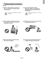
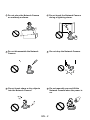
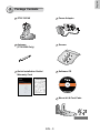
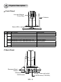
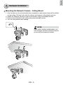
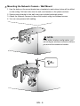
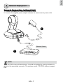
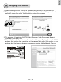
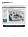
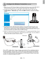
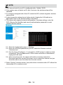
PT8133/33W
Quick Installation Guide
English
All specifications are subject to change without notice. Copyright c 2011 VIVOTEK INC. All rights reserved. P/N:625016400G
VIVOTEK INC.
6F, No.192, Lien-Cheng Rd., Chung-Ho, New Taipei City, 235, Taiwan, R.O.C.
|T: +886-2-82455282| F: +886-2-82455532| E: [email protected]
VIVOTEK USA, INC.
2050 Ringwood Avenue, San Jose, CA 95131
|T: 408-773-8686| F: 408-773-8298| E: [email protected]
繁中
簡中
日本語
Français
Español
Deutsch
PT8133: 1MP • PoE
PT8133W: 1MP • WPS • 802.11n
Português
Italiano
Türkçe
Polski
Русский
Česky
Svenska
English
Warning Before Installation
Power off the Network Camera as
soon as smoke or unusual odors
are detected.
Keep the Network Camera
away from water. If the Network
Camera becomes wet, power off
immediately.
Contact your distributor in the event of
occurrence.
Contact your distributor in the event of
occurrence.
Do not place the Network Camera
around heat sources, such as a
television or oven.
Refer to your user’s manual for the
operating temperature.
Keep the Network Camera away
from direct sunlight.
Do not place the Network Camera
in high humidity environments.
EN - 1
Do not place the Network Camera
on unsteady surfaces.
Do not touch the Network Camera
during a lightning storm.
Do not disassemble the Network
Camera.
Do not drop the Network Camera.
Do not insert sharp or tiny objects
into the Network Camera.
Do not manually pan and tilt the
Network Camera when the power is
on.
EN - 2
English
1
Package Contents
PT8133/33W
Power Adapter
Antenna
(PT8133W Only)
Screws
Quick Installation Guide /
Warranty Card
Software CD
5 0 0 0 2 47 0 1 G
Mount kit & Foot Pads
EN - 3
2
Physical Description
Front Panel
Lens and Manual
Focus Ring
Antenna
Status LEDs
LED Definitions
Item
LED status
Description
1
Steady Red
Red LED off
Blink Green every 1 sec. + Steady Red
Green LED off + Steady Red
Blink Red every 0.15 sec. + Blink Green every 1 sec.
Blink Red every 0.15 sec. + Blink Green every 0.15 sec.
Steady Blue
Blue LED off
Blink Blue every 0.15 sec.
Power on and system boot
Power off
Network connected (heartbeat)
Network failed
Upgrading firmware
Restoring defaults
Linked to a wireless AP
Not connected to wireless network
WPS searching
2
3
4
5
6
Back Panel
ETHERNET
Recessed Reset
Button
WPS
Ethernet 10/100
RJ45 Socket
12V
1.5A
Power cord socket
WPS button (PT8133W)
EN - 4
English
3
Hardware Installation
Mounting the Network Camera - Ceiling Mount
1. Use the holes on the mount bracket as a template to mark where holes will be drilled
on the ceiling. Drill two holes into the ceiling; and hammer in the plastic anchors.
2. Attach the Network Camera to the mount bracket using two flathead screws.
3. Secure mount bracket to the ceiling using two panhead screws.
4. You can now proceed with cabling.
NOTE:
If you prefer wireless configuration, you
can configure wireless connection before
you mount the camera to bracket.
EN - 5
Mounting the Network Camera - Wall Mount
1. Use the holes on the mount bracket as a template to mark where holes will be drilled
on the ceiling. Drill two holes into the wall; and hammer in the plastic anchors.
2. Secure mount bracket to the wall using two included panhead screws.
3. Attach the Network Camera to the mount bracket using two flathead screws.
4. You can now proceed with cabling.
NOTE:
If you prefer wireless configuration, you
can configure wireless connection before
you mount the camera to bracket.
2
EN - 6
English
4
Network Deployment
General Connection (without PoE)
1. Connect the camera to a switch via Ethernet cable.
2. Connect the supplied power adapter between the camera and a power outlet.
2
ET
ETHERN
12V
1.5A
Ethernet Switch
1
POWER
COLLISION
1
2
3
4
5
LINK
RECEIVE
PARTITION
NOTE:
The PT8133W comes with an antenna. It should be installed by turning clockwise to
attach to the associated connector. The wireless model, PT8133W, does not support
PoE.
EN - 7
Power over Ethernet (PoE)
When using a PoE-enabled switch
The PT8133 Network Camera is PoE-compliant, allowing transmission of power and
data via a single Ethernet cable. Follow the below illustration to connect the camera to a
PoE enabled switch via a CAT5e Ethernet cable.
12V
1.5A
ETHERNET
POWER
COLLISION
1
2
3
4
LINK
RECEIVE
PARTITION
5
PoE switch
When using a non-PoE switch
Use a PoE power injector (optional) to connect between the Network Camera and a
non-PoE switch.
ETHERNET
PoE Power Injector
(optional)
12V
1.5A
POWER
COLLISION
1
2
3
4
5
LINK
RECEIVE
PARTITION
Non-PoE Switch
EN - 8
English
5
Assigning an IP Address
1. Install “Installation Wizard 2” from the Software Utility directory on the software CD.
2. The program will conduct an analysis of your network environment. After your network is
analyzed, please click on the “Next” button to continue the program.
IW2
Installation
Wizard 2
3.The program will search for VIVOTEK Video Receivers, Video Servers, and Network
Cameras on the same LAN.
4.After a brief search, the main installer window will pop up. Double-click on the MAC
address that matches the one printed on the camera label or the S/N number on the
package box label to open a browser management session with the Network Camera.
172.16.7.13
0002D10766AD
0002D10766AD
EN - 9
PZ71X2
PZ81X1
6
Ready to Use
1.A browser session with the Network Camera should prompt as shown below.
2.You should be able to see live video from your camera. You may also install the
32-channel recording software from the software CD in a deployment consisting of
multiple cameras. For its installation details, please refer to its related documents.
Wireless Mega-Pixel Network Camera
For further setup, please refer to the user's manual on the software CD.
EN - 10
English
7
Configure the Wireless Connection (PT8133W)
1. Make sure your AP (Access Point) and Operating System support the WPS (Wi-Fi
Protected Setup) functions. WPS enables easy setup with compatible APs.
2. Connect your camera using a LAN cable, open a web console, and enter the
Configuration -> Wireless page. Select the WPS checkbox, and click the Save
button.
3. The camera's blue LED should start flashing. Press and hold down both of the
WPS buttons on your AP and your camera for at least 1 second. (Some router/
AP will have a virtual button on their management software instead.) Refer to your
AP's documentation for details using its WPS function.
4. Wait for 2 minutes with the onscreen progress bar. The camera should then reboot.
When the progress bar disappears, disconnect your LAN cable. You can refresh or
re-start your web console to see live video.
PT8133W
ADSL/Cab
le/Hub
ET
ETHERN
Wireless AP
12V
1.5A
WPS buttons
WPS
When WPS configuration is done, wireless connectivity will be established and the
security encryption, such as WEP or WPA-PSK, will be synchronized with the AP.
Use the IW2 utility to find the camera. As for IP setting, the camera's use of DHCP
or static IP is determined by your configuration on the network camera via the web
console. The camera's default is DHCP.
EN - 11
NOTE:
1.WPS may not work if your AP is configured with a "hidden" SSID.
2.If the camera can not detect an AP after 2 minutes, the wireless setup will be
cancelled.
3.If a camera is assigned with a fixed IP outside the AP's network segment, wireless
setup will fail.
4.A wired connection always has a higher priority. Unplug the LAN cable at an
appropriate time for the wireless setup to take effect.
5.The camera also supports manual configuration of wireless settings, enter the
SSID (Service Set Identifier) and security authentication password in a web
console with the camera.
5-1. Enter the Configuration page -> Wireless.
5-2. Enter the SSID and password of your AP, select the Wireless mode as
"Infrastructure."
5-3. Use the "ping <IP address> -t" command in a DOS prompt to observe wired
connectivity. Click the Save button. When wired connection is discontinued,
unplug the LAN cable.
5-4. After several seconds, the camera will switch to wireless connection.
Disconnect and then connect the power cord to restart the camera, and you
should be able to see live video from the web console.
6.Select "Ad-Hoc" wireless mode if you prefer direct connection with a PC without the
intermediate AP or wireless router.
EN - 12
PT8133/33W
Quick Installation Guide
English
All specifications are subject to change without notice. Copyright c 2011 VIVOTEK INC. All rights reserved. P/N:625016400G
VIVOTEK INC.
6F, No.192, Lien-Cheng Rd., Chung-Ho, New Taipei City, 235, Taiwan, R.O.C.
|T: +886-2-82455282| F: +886-2-82455532| E: [email protected]
VIVOTEK USA, INC.
2050 Ringwood Avenue, San Jose, CA 95131
|T: 408-773-8686| F: 408-773-8298| E: [email protected]
繁中
簡中
日本語
Français
Español
Deutsch
PT8133: 1MP • PoE
PT8133W: 1MP • WPS • 802.11n
Português
Italiano
Türkçe
Polski
Русский
Česky
Svenska


![Cover [PZ81x1,x1W].ai](http://vs1.manualzilla.com/store/data/006040535_1-42ed705d921c196e7271c308c8c31f51-150x150.png)