1
Agilent E364xA
Dual Output DC Power
Supplies
User’s and Service Guide
Agilent Technologies
Notices
© Agilent Technologies, Inc., 2000–2013
Warranty
No part of this manual may be reproduced in
any form or by any means (including electronic storage and retrieval or translation
into a foreign language) without prior agreement and written consent from Agilent
Technologies, Inc. as governed by United
States and international copyright laws.
The material contained in this document is
provided “as is,” and is subject to change,
without notice, in future editions. Further,
to the maximum extent permitted by the
applicable law, Agilent disclaims all warranties, either express or implied, with
regard to this manual and any information
contained herein, including but not limited
to the implied warranties of merchantability and fitness for a particular purpose.
Agilent shall not be liable for errors or for
incidental or consequential damages in
connection with the furnishing, use, or
performance of this document or of any
information contained herein. Should Agilent and the user have a separate written
agreement with warranty terms covering
the material in this document that conflict
with these terms, the warranty terms in
the separate agreement shall control.
Manual Part Number
E3646-90001
Edition
Tenth Edition, August 6, 2013
Agilent Technologies, Inc.
5301, Stevens Creek Blvd.
Santa Clara, CA 95051 USA
Technology Licenses
The hardware and or software described in
this document are furnished under a license
and may be used or copied only in accordance with the terms of such license.
Restricted Rights Legend
U.S. Government Restricted Rights. Software and technical data rights granted to
the federal government include only those
rights customarily provided to end user customers. Agilent provides this customary
commercial license in Software and technical data pursuant to FAR 12.211 (Technical
Data) and 12.212 (Computer Software) and,
for the Department of Defense, DFARS
252.227-7015 (Technical Data - Commercial
Items) and DFARS 227.7202-3 (Rights in
Commercial Computer Software or Computer Software Documentation).
II
Safety Notices
CAUTION
A CAUTION notice denotes a hazard. It calls attention to an operating procedure, practice, or the likes
of that, if not correctly performed
or adhered to, could result in damage to the product or loss of important data. Do not proceed beyond a
CAUTION notice until the indicated
conditions are fully understood and
met.
WA R N I N G
A WARNING notice denotes a
hazard. It calls attention to an
operating procedure, practice, or
the likes of that, if not correctly
performed or adhered to, could
result in personal injury or death.
Do not proceed beyond a WARNING notice until the indicated
conditions are fully understood
and met.
E364xA User’s and Service Guide
Safety Symbols
The following symbols on the instrument and in the documentation
indicate precautions which must be taken to maintain safe operation of
the instrument.
Caution, risk of danger (refer to this manual
for specific Warning or Caution information)
In position of a bi-stable push control
DC (Direct current or voltage)
Terminal is at earth potential. Used for
measurement and control circuits designed to
be operated with one terminal at earth
potential.
AC (Alternating current or voltage)
Positive binding post
Protective conductor terminal
Negative binding post
Out position of a bi-stable push control
E364xA User’s and Service Guide
III
Safety Considerations
Read the information below before using this instrument.
The following general safety precautions must be observed during all
phases of operation, service, and repair of this instrument. Failure to
comply with these precautions or with specific warnings elsewhere in this
manual violates safety standards for design, manufacture, and intended
use of the instrument. Agilent Technologies assumes no liability for the
customer’s failure to comply with these requirements.
CAUTION
• Use the device with the cables provided with the shipment.
• If the device is used in a manner not specified by the manufacturer,
the device protection may be impaired.
• Always use a dry cloth to clean the device. Do not use ethyl alcohol
or any other volatile liquid to clean the device.
• Do not permit any blockage of the ventilation holes of the device.
IV
E364xA User’s and Service Guide
WA R N I N G
• Do not use MAINS supply cords by inadequately RATED cord.
Always use the MAINS supply cord provided by the manufacturer.
• Do not use the device if it appears damaged or defective. REMOVE
POWER and do not use the device until safe operation is verified
by service-trained personnel. If necessary, return the device to
Agilent for service and repair to ensure that the safety features
are maintained.
• Do not operate the device around flammable gases or fumes,
vapor, or wet environments.
• Observe all markings on the device before connecting any wiring
to the device.
• Turn off the output of the power supply before connecting to the
output terminals.
• When servicing the device, use only the specified replacement
parts.
• Do not install substitute parts or perform any unauthorized
modification to the device. Return the device to Agilent for service
and repair to ensure that the safety features are maintained.
• Do not operate the device with the cover removed or loosened.
This power supply is a Safety Class I instrument, which means that it has a
protective earth terminal. This terminal must be connected to earth ground
through a power source with a 3-wire ground receptacle.
Before installation or operation, check the power supply and review this
manual for safety markings and instructions. Safety information for
specific procedures is located at the appropriate places in this manual.
E364xA User’s and Service Guide
V
Safety and EMC Requirements
This power supply is designed to comply with the following safety and
Electromagnetic Compatibility (EMC) requirements:
• IEC61326-1:2005/EN61326-1:2006
• Canada: ICES/NMB-001: Issue 4, June 2006
• Australia/New Zealand: AS/NZS CISPR11:2004
• IEC 61010-1:2001/EN 61010-1:2001
• Canada: CAN/CSA-C22.2 No. 61010-1-04
• USA: ANSI/UL 61010-1:2004
Environmental Conditions
This instrument is designed for indoor use. The table below shows the
general environmental requirements for this instrument.
VI
Environmental condition
Requirements
Temperature
Operating condition
• 0 °C to 40 °C (full rated output)
Storage condition
• –20 °C to 70 °C
Humidity
Operating condition
• 95% RH (maximum)
Altitude
Up to 2000 m
Installation category
II (for indoor use)
Pollution degree
2
E364xA User’s and Service Guide
Regulatory Markings
The CE mark is a registered trademark
of the European Community. This CE
mark shows that the product complies
with all the relevant European Legal
Directives.
The C-tick mark is a registered
trademark of the Spectrum
Management Agency of Australia. This
signifies compliance with
the Australia EMC Framework
regulations under the terms of the
Radio Communication Act of 1992.
ICES/NMB-001 indicates that this ISM
device complies with the Canadian
ICES-001.
Cet appareil ISM est confomre a la
norme NMB-001 du Canada.
This instrument complies with the
WEEE Directive (2002/96/EC) marking
requirement. This affixed product label
indicates that you must not discard
this electrical or electronic product in
domestic household waste.
The CSA mark is a registered
trademark of the Canadian Standards
Association.
This symbol indicates the time period
during which no hazardous or toxic
substance elements are expected to
leak or deteriorate during normal use.
Forty years is the expected useful life
of the product.
This symbol is a South Korean Class A
EMC Declaration. This is a Class A
instrument suitable for professional
use and in electromagnetic
environment outside of the home.
E364xA User’s and Service Guide
VII
Waste Electrical and Electronic Equipment (WEEE) Directive 2002/96/EC
This instrument complies with the WEEE Directive (2002/96/EC) marking
requirement. This affixed product label indicates that you must not discard
this electrical or electronic product in domestic household waste.
Product Category:
With reference to the equipment types in the WEEE directive Annex 1, this
instrument is classified as a “Monitoring and Control Instrument” product.
The affixed product label is as shown below.
Do not dispose in domestic household waste.
To return this unwanted instrument, contact your nearest Agilent Service
Center, or visit
www.agilent.com/environment/product
for more information.
VIII
E364xA User’s and Service Guide
Declaration of Conformity (DoC)
The Declaration of Conformity (DoC) for this instrument is available on the
Agilent Web site. You can search the DoC by its product model or
description at the Web address below.
http://regulations.corporate.agilent.com/DoC/search.htm
NOTE
E364xA User’s and Service Guide
If you are unable to search for the respective DoC, contact your local
Agilent representative.
IX
THIS PAGE HAS BEEN INTENTIONALLY LEFT BLANK.
X
E364xA User’s and Service Guide
Table of Contents
1
Getting Started
Introduction
2
Standard Shipped Items
Options 6
Accessories 7
6
Preparing the Power Supply 8
Checking the power supply 8
Connecting power to the power supply
Checking the output 10
Converting line voltage 12
Rack-mounting the power supply 14
9
Product at a Glance 17
Front panel 17
Rear panel 20
Display annunciators 21
Output Connections 23
Current ratings 23
Voltage drops 24
Load consideration 24
Remote voltage sensing connections
Multiple loads 29
Operating the Power Supply
Cooling 30
Bench operation 30
Cleaning 30
2
30
Operation and Features
Overview
E364xA User’s and Service Guide
26
32
XI
Constant Voltage Operation 34
Front panel operation 34
Remote interface operation 36
Constant Current Operation 36
Front panel operation 36
Remote interface operation 38
Track Mode Operation 38
Front panel operation 39
Remote interface operation
39
View Menu Operation 40
Changing the display mode 40
Viewing the errors 41
Viewing the firmware revision 41
Viewing the calibration string 42
Configuring the Remote Interface
GPIB configuration 43
RS-232 configuration 43
42
Storing and Recalling Operating States
Front panel operation 44
Remote interface operation 46
Programming the Overvoltage Protection
Front panel operation 46
Remote interface operation 49
44
46
Disabling the Output 50
Front panel operation 50
Remote interface operation 50
Disconnecting the output using an external relay
System-Related Operations
State storage 52
Self-test 53
XII
51
52
E364xA User’s and Service Guide
Error conditions 54
Firmware revision query 54
SCPI language version 55
GPIB Interface Reference
56
RS-232 Interface Reference 57
RS-232 configuration overview 57
RS-232 data frame format 58
Connection to a computer or terminal
RS-232 troubleshooting 60
58
Calibration 61
Calibration security 61
To unsecure for calibration 62
To secure against calibration 63
To change the security code 64
Calibration count 65
Calibration message 66
3
Remote Interface Reference
SCPI Command Summary
68
Introduction to the SCPI Language 74
Command format used in this manual 75
Command separators 76
Using the MIN and MAX parameters 77
Querying parameter settings 77
SCPI command terminators 78
IEEE-488.2 common commands 78
SCPI parameter types 78
Simplified Programming Overview 80
Using the APPLy command 80
Using the low-level commands 80
Reading a query response 81
E364xA User’s and Service Guide
XIII
Selecting a trigger source 81
Power supply programming ranges
82
Using the APPLy Command 83
APPLy {<voltage>| DEF | MIN | MAX}[,{<current>| DEF | MIN
| MAX}] 83
APPLy? 83
Output Settings and Operation Commands
84
Triggering Commands 92
Trigger source choices 92
Triggering commands 94
System-Related Commands
State Storage Commands
Calibration Commands
Calibration example
95
99
101
104
Interface Configuration Commands
106
SCPI Status Registers 107
What is an event register? 107
What is an enable register? 107
What is a multiple logical output? 108
SCPI status system 109
Questionable Status register 110
Standard Event register 112
Status byte register 114
Using service request (SRQ) and serial poll 115
Using *STB? to read the Status Byte 116
Using the Message Available Bit (MAV) 116
Using SRQ to interrupt the bus controller 117
Determining when a command sequence is completed
Using *OPC to signal when data is in the output buffer
Status Reporting Commands
XIV
117
118
119
E364xA User’s and Service Guide
Halting an Output in Progress
124
SCPI Conformance Information
SCPI confirmed commands
Device-specific commands
125
125
127
IEEE-488 Conformance Information 128
Dedicated hardware lines 128
Addressed commands 128
IEEE-488.2 common commands 129
4
Error Messages
Overview 132
Front panel operation 132
Remote interface operation 133
Execution Error Messages
Self-Test Error Messages
134
139
Calibration Error Messages
5
141
Application Programs
Overview
144
Example Program for C and C++
Example Program for Excel 97
6
145
149
Tutorial
Overview of the Power Supply Operation
156
Output Characteristics 158
Unregulated state 160
Unwanted signals 160
Extending the Voltage Range and Current Range
Series connections 163
E364xA User’s and Service Guide
163
XV
Parallel connections
Remote Programming
7
164
165
Characteristics and Specifications
Physical Characteristics
170
Environmental Characteristics
Electrical Specifications
172
Supplemental Characteristics
8
172
174
Service and Maintenance
Overview
178
Operating Checklist
179
Types of Service Available 180
Standard repair service (worldwide)
Repacking for Shipment
181
Electrostatic Discharge (ESD) Precautions
Surface Mount Repair
180
182
183
Replacing the Power-Line Fuse
183
Troubleshooting Hints 184
Unit reports errors 740 to 755 184
Unit fails self-test 184
Bias supplies problems 185
Self-Test Procedures 186
Power-on self-test 186
Complete self-test 186
General Disassembly
188
Recommended Test Equipment
XVI
189
E364xA User’s and Service Guide
Test Considerations
191
Operation Verification and Performance Tests
Operation verification tests 192
Performance tests 192
Measurement Techniques 193
Common test setup 193
Current-monitoring resistor 194
General measurement techniques
Electronic load 195
Programming 195
192
194
Constant Voltage (CV) Verifications 196
Constant voltage test setup 196
Voltage programming and readback accuracy
CV load effect (load regulation) 198
CV source effect (line regulation) 199
CV PARD (ripple and noise) 200
Load transient response time 202
Constant Current (CC) Verifications 204
Constant current test setup 204
Current programming and readback accuracy
CC load effect (load regulation) 206
CC source effect (line regulation) 207
CC PARD (ripple and noise) 208
Common Mode Current Noise
Performance Test Record
196
204
210
211
Calibration Reference 214
Agilent calibration services 214
Calibration interval 214
To unsecure the power supply without the security code
General Calibration or Adjustment Procedure
E364xA User’s and Service Guide
214
216
XVII
Front panel voltage and current calibration
Calibration Record
217
221
Calibration Error Messages
222
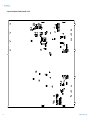
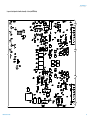
Component Locator Diagram 225
Component locator diagram for the main board assembly —
top 225
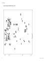
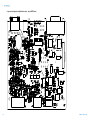
Component locator diagram for the main board assembly —
bottom 226
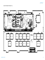
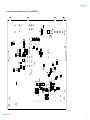
Component locator diagram for the digital board assembly —
top 227
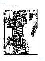
Component locator diagram for the digital board assembly —
bottom 228
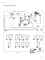
Component locator diagram for the front panel — top 229
Component locator diagram for the main board assembly — top
(serial MY53xx6xxx) 230
Component locator diagram for the main board assembly —
bottom (serial MY53xx6xxx) 231
Component locator diagram for the digital board assembly —
top (serial MY53xx6xxx) 232
Component locator diagram for the digital board assembly —
bottom (serial MY53xx6xxx) 233
Component locator diagram for the front panel — top (serial
MY53xx6xxx) 234
XVIII
E364xA User’s and Service Guide
List of Figures
Figure 1-1
Figure 1-2
Figure 1-3
Figure 1-4
Figure 1-5
Figure 1-6
Figure 1-7
Figure 2-1
Figure 2-2
Figure 2-3
Figure 3-1
Figure 3-2
Figure 5-1
Figure 6-1
Figure 6-2
Figure 6-3
Figure 6-4
Figure 6-5
Figure 6-6
Figure 6-7
Figure 6-8
Figure 7-1
Figure 7-2
Figure 8-1
Figure 8-2
Figure 8-3
Figure 8-4
Figure 8-5
Figure 8-6
E364xA User’s and Service Guide
Rear output terminals 5
Line voltage selector (set for 115 Vac) 12
Front panel 17
Voltage and current limit settings 19
Rear panel 20
Display annunciators 21
Remote voltage sensing connections 26
Recommended protection circuit for battery
charging 49
DB-9 serial connection 59
DB-25 serial connection 60
Multiple logical output 108
SCPI status system 109
Example program result 149
Diagram of a simple series power supply 156
Block diagram of the power supply showing the remote
interface isolation 157
Ideal constant voltage power supply 158
Ideal constant current power supply 158
Output characteristics 159
Simplified diagram of the common mode and normal
mode sources of noise 162
Speed of response — programming up (full load) 165
Speed of response — programming down 166
E364xA dimensions 170
E364xA dimensions for rack-mounting 171
General disassembly 188
Performance verification test setup 193
Front or rear panel terminal connections 194
CV PARD (ripple and noise) 201
Transient response time 203
CC PARD connections (ripple and noise) 209
XIX
THIS PAGE HAS BEEN INTENTIONALLY LEFT BLANK.
XX
E364xA User’s and Service Guide
List of Tables
Table 1-1
Table 1-2
Table 1-3
Table 1-4
Table 1-5
Table 1-6
Table 1-7
Table 2-1
Table 3-1
Table 3-2
Table 3-3
Table 3-4
Table 3-5
Table 3-6
Table 3-7
Table 3-8
Table 4-1
Table 4-2
Table 4-3
Table 7-1
Table 7-2
Table 7-3
Table 8-1
Table 8-2
Table 8-3
Table 8-4
Table 8-5
Table 8-6
Table 8-7
Table 8-8
Table 8-9
Table 8-10
E364xA User’s and Service Guide
E364xA options 6
E364xA accessories 7
E364xA power-line fuse 9
Front panel overview 17
Rear panel overview 20
Display annunciators overview 21
Wire rating 23
Factory-setting security codes 62
SCPI command summary 69
Agilent E364xA programming ranges 82
Power supply state 98
Bit definitions — Questionable Status register 110
Bit definitions — Standard Event register 112
Bit definitions — Status Byte summary register 114
SCPI confirmed commands 125
Non-SCPI commands 127
Execution error messages 134
Self-test error messages 139
Calibration error messages 141
Physical characteristics 170
Electrical specifications 172
Supplemental characteristics 174
Bias supplies voltages 185
Bias supplies voltages (serial MY53xx6xxx) 185
Self-test error messages 186
Recommended test equipment 189
Verification programming values 196
CV performance test record 211
CC performance test record 212
Parameters for calibration 216
Calibration record 221
Calibration error messages 222
XXI
THIS PAGE HAS BEEN INTENTIONALLY LEFT BLANK.
XXII
E364xA User’s and Service Guide
E364xA Dual Output DC Power Supplies
User’s and Service Guide
1
Getting Started
Introduction 2
Standard Shipped Items 6
Preparing the Power Supply 8
Product at a Glance 17
Output Connections 23
Operating the Power Supply 30
This chapter guides you to set up your power supply for the
first time. An introduction to all the features of the power
supply is also given.
Agilent Technologies
1
1
Getting Started
Introduction
Introduction
The Agilent E3646A/E3647A (30 W) and E3648A/E3649A
(50 W) are high performance dual output dual range
programmable DC power supplies with GPIB and RS- 232
interfaces. The combination of bench- top and system
features in these power supplies provides versatile solutions
for your design and test requirements.
Convenient bench-top features
• Dual output dual range
• Output on/off
• High accuracy and high resolution
• Excellent load and line regulation
• Low ripple and noise
• Overvoltage protection
• Five operating states storage
• Tracking operation
• Easy- to- use controls
• Remote voltage sensing
• Front and rear output terminals
• Portable, ruggedized case with non- skid feet
• Error messages available on the display
Flexible system features
• Standard GPIB (IEEE- 488) and RS- 232 interfaces
• Standard Commands for Programmable Instruments
(SCPI) compatibility
• Easy I/O setup from the front panel
• Software calibration, no internal physical adjustments
2
E364xA User’s and Service Guide
Getting Started
Introduction
1
The E364xA power supplies feature a combination of
programming capabilities and linear power supply
performance that makes them ideal for power systems
applications. The E364xA power supplies may be
programmed locally from the front panel or remotely over
the GPIB and RS- 232 interfaces.
The E364xA power supplies have two ranges, allowing more
voltage at a lower current or more current at a lower
voltage. The output range is selected from the front panel or
over the remote interfaces.
Operational features
• Dual output dual range
• Constant voltage (CV) or constant current (CC) operation
• Overvoltage protection (OVP)
• Five storage locations (1 to 5) for user- defined
operating states
• Automatic turn- on self- test
• Remote sense at rear panel terminals
• User calibration from the front panel or over the remote
interfaces
Front panel operations
• Easy- to- use control features
• Output (1 or 2) and output voltage range selection
• Enabling or disabling OVP
• OVP trip level setting and condition clearing
• Setting and displaying the voltage and current limit values
• Storing or recalling the operating state
• Resetting the power supply to the power- on state
• Returning the power supply to the local mode from the
remote mode
• Retrieving or scrolling error messages on the display
• Changing the display mode (V- V, I- I, or V- I display)
E364xA User’s and Service Guide
3
1
Getting Started
Introduction
• Viewing the errors, calibration string, or system firmware
revision
• Enabling or disabling the Tracking mode
• Calibrating the power supply, including changing the
calibration secure code
• Configuring the remote interface
• Enabling or disabling the output
When operated over the remote interface, the E364xA power
supplies can be both a listener and a talker. Using an
external controller, you can instruct the power supply to set
the output and to send the status data back over the GPIB
or RS- 232 interface. Capabilities include the following
features:
• Voltage and current programming
• Voltage and current readback
• Present and stored status readback
• Programming syntax error detection
• Complete self- test
The front panel Vacuum- Fluorescent Display (VFD) includes:
• Displaying the actual values of the output voltage and
current (meter mode)
• Displaying the limit values of the voltage and current
(limit mode)
• Checking the operating status from the annunciators
• Checking the type of error from the error codes
(messages)
Front panel binding posts are available to connect load wires
for bench operation. Connections to the power supply’s
output and to chassis ground are made to the rear output
terminals.
4
E364xA User’s and Service Guide
Getting Started
Introduction
WA R N I N G
1
Floating the power supply output at more than ±60 Vdc from the
chassis presents an electric shock hazard to the user.
Do not float the outputs at more than ±60 Vdc when uninsulated
sense wires are used to connect the (+) output to the (+) sense and
the (–) output to the (–) sense terminals on the back of the unit.
Figure 1-1 Rear output terminals
E364xA User’s and Service Guide
1 Float voltage ±60 Vdc Max to
without insulation).
(shorting conductors
2 Float voltage ±240 Vdc Max to
conductors).
(insulated shorting
5
1
Getting Started
Standard Shipped Items
Standard Shipped Items
Verify that you have received the following items in the
shipment of your power supply. If anything is missing or
damaged, contact your nearest Agilent Sales Office.
✔ Power cord
✔ Certificate of Calibration
✔ E364xA User’s and Service Guide (this manual)
✔ E364xA Quick Reference Card
Options
Options 0EM, 0E3, and 0E9 determine which power- line
voltage is selected at the factory. The standard unit is
configured for 115 Vac ±10%, 47 Hz to 63 Hz input voltage.
For more information about changing the power- line voltage
setting, refer to “Converting line voltage” on page 12.
Table 1-1 E364xA options
Option
Description
OEM
115 Vac ±10%, 47 Hz to 63 Hz input voltage
OE3
230 Vac ±10%, 47 Hz to 63 Hz input voltage
OE9
100 Vac ±10%, 47 Hz to 63 Hz input voltage
1CM
Rack-mount kit (Agilent part number 5063-9243)
OL2
Extra English manual set (local language manual files are included in the
CD-ROM, Agilent part number 5964-8251)
6
E364xA User’s and Service Guide
Getting Started
Standard Shipped Items
1
Accessories
The accessories listed below may be ordered from your local
Agilent Sales Office either with the power supply or
separately.
Table 1-2 E364xA accessories
Part number
Description
10833A
GPIB cable, 1 m (3.3 ft.)
10833B
GPIB cable, 2 m (6.6 ft.)
34398A
• RS-232, 9 pin (f) to 9 pin (f), 2.5 m (8.2 ft.) cable
• 9 pin (f) to 25 pin (m) adapter
E364xA User’s and Service Guide
7
1
Getting Started
Preparing the Power Supply
Preparing the Power Supply
Checking the power supply
1 Check the shipped items.
Verify that you have received the items listed in “Standard
Shipped Items” on page 6. If anything is missing or
damaged, contact your nearest Agilent Sales Office.
2 Connect the power cord and turn on the power supply.
The front panel display will light up briefly while the
power supply performs its power- on self- test. The GPIB
address is also displayed. To review the power- on display
with all annunciators turned on, hold down Display
as you
Limit
turn on the power supply. If the power supply does not
turn on properly, refer to “Connecting power to the power
supply” on page 9.
3 Perform a complete self- test.
The complete self- test performs a more extensive set of
tests than those performed at power- on. Hold down Display
Limit
as you turn on the power supply and hold down the key
until you hear a long beep. The self- test will begin when
you release the key following the beep.
If the self- test fails, refer to Chapter 8, “Service and
Maintenance” for instructions on returning the power
supply to Agilent for service.
NOTE
8
The power supply is shipped from the factory with a power-line cord that
has a plug appropriate for your location. Your power supply is equipped
with a 3-wire grounding type power cord; the third conductor being the
ground. The power supply is grounded only when the power-line cord is
plugged into an appropriate receptacle. Do not operate your power supply
without adequate cabinet ground connection.
E364xA User’s and Service Guide
Getting Started
Preparing the Power Supply
1
Connecting power to the power supply
If the power supply does not turn on
Use the following steps to help solve problems you might
encounter when turning on the instrument. If you need more
help, refer to Chapter 8, “Service and Maintenance” for
instructions on returning the instrument to Agilent
for service.
1 Verify that there is AC power to the power supply.
First, verify that the power cord is firmly plugged into the
power receptacle on the rear panel of the power supply.
You should also make sure that the power source you
plugged the power supply into is energized. Then, verify
that the power supply is turned on.
2 Verify the power- line voltage setting.
The line voltage is set to the proper value for your
country when the power supply is shipped from the
factory. Change the voltage setting if it is not correct. The
settings are 100 Vac, 115 Vac, or 230 Vac.
3 Verify that the correct power- line fuse is installed.
The correct fuse is installed for your country when the
power supply is shipped from the factory. Refer to
Table 1- 3 to replace the fuse for your power supply.
Table 1-3 E364xA power-line fuse
Model
Agilent part number
Part description
E3646A
2110-1550
Fuse 2.5 A T 125 V for 100 Vac and 115 Vac
E3647A
2110-1346
Fuse 1 A T 250 V for 230 Vac
E3648A
2110-0996
Fuse 4 A T 250 V for 100 Vac and 115 Vac
E3649A
2110-1548
Fuse 2 A T 250 V for 230 Vac
E364xA User’s and Service Guide
9
1
Getting Started
Preparing the Power Supply
Checking the output
The following procedures ensure that the power supply
develops its rated outputs and properly responds to
operation from the front panel. For complete performance
and verification tests, refer to Chapter 8, “Service and
Maintenance”.
If an error is detected during the output checkout procedures, the ERROR
annunciator will turn on. Refer to Chapter 4, “Error Messages” for
more information.
NOTE
Voltage output check
The following steps verify the basic voltage functions with
no load.
Power
1 Turn on the power supply.
The power supply will go into the power- on/reset state,
the outputs are disabled (the OFF annunciator turns on),
and its output1 and low voltage range are selected. The
OVP1, OVP2, OUT1, and low voltage range indication
annunciators turn on (for example, the 8 V annunciator
turns on for the E3646A model), and the knob is selected
for the voltage control.
Output
On/Off
2 Enable the outputs.
The OFF annunciator turns off and the CV annunciator
turns on. Notice that the display is in the meter mode.
Meter mode means that the display shows the actual
output voltage and current.
3 Check that the front panel voltmeter properly responds to
the knob control for both the low and high voltage ranges.
Turn the knob clockwise or counter- clockwise to check
that the voltmeter responds to the knob control and the
ammeter indicates nearly zero. The flashing digit can be
adjusted by turning the knob.
1
4 Ensure that the voltage can be adjusted from zero to the full
rated value by adjusting the knob.[1]
[1] You can use the resolution selection keys to move the flashing digit to the right
or left when setting the voltage.
10
E364xA User’s and Service Guide
Getting Started
Preparing the Power Supply
1
Current output check
The following steps check the basic current functions with a
short across the power supply’s output.
Power
1 Turn on the power supply.
Make sure that the output is disabled. The OFF
annunciator is turned on.
2 Connect a short across the (+) and (–) output terminals with
an insulated test lead.
Use a wire size sufficient to handle the maximum current.
Refer to Table 1- 7 for more information.
Output
On/Off
3 Enable the output.
The CV or CC annunciator turns on depending on the
resistance of the test lead. Notice that the display is in
the meter mode.
Display
Limit
4 Adjust the voltage limit value to 1.0 V.
Set the display to the limit mode (the Limit annunciator
will be flashing). Adjust the voltage limit to 1.0 V to
assure the CC operation. The CC annunciator will turn on.
To return to the normal mode, press the Display
key again
Limit
or let the display time- out after several seconds.
Voltage
Current
5 Set the knob to the current control to check that the front
panel ammeter properly responds to the knob control.
Turn the knob clockwise or counter- clockwise when the
display is in the meter mode (the Limit annunciator is
turned off). Check that the ammeter responds to the knob
control and the voltmeter indicates nearly zero (the
voltmeter will show the voltage drop caused by the test
lead). The flashing digit can be adjusted by turning the
knob.
1
6 Ensure that the current can be adjusted from zero to the full
rated value.[1]
7 Turn off the power supply and remove the short from the
output terminals.
[1] You can use the resolution selection keys to move the flashing digit to the right
or left when setting the current.
E364xA User’s and Service Guide
11
1
Getting Started
Preparing the Power Supply
Converting line voltage
WA R N I N G
Shock Hazard Operating personnel must not remove the power
supply covers. Component replacement and internal adjustments
must be made only by qualified service personnel.
Line voltage conversion is accomplished by adjusting two
components: the line voltage selection switch and the
power- line fuse on the rear panel.
1 Remove the AC line power.
2 Remove the cover. Refer to “General Disassembly” on
page 188.
3 Set the two sections of the line voltage selector switch on
the PC board for the desired line voltage. Refer to
Figure 1- 2.
4 Refer to “Replace the power- line fuse” on page 13 to
check the rating of the power- line fuse and replace with
the correct one if necessary.
5 Replace the cover and mark the power supply clearly with
a tag or label indicating the correct line voltage and fuse
that is in use.
100 V
115 V
230 V
Top view
Figure 1-2 Line voltage selector (set for 115 Vac)
12
E364xA User’s and Service Guide
Getting Started
Preparing the Power Supply
1
Replace the power-line fuse
1 Remove the power cord, and remove the fuse- holder
assembly from the rear panel with a flat- blade
screwdriver.
2 Remove the fuse- holder from the assembly.
3 Replace with the correct fuse.
E364xA User’s and Service Guide
13
1
Getting Started
Preparing the Power Supply
4 Replace the fuse- holder assembly in the rear panel.
NOTE
Verify that the correct line voltage is selected and the power-line fuse
is good.
Rack-mounting the power supply
You can mount the power supply in a standard 19- inch rack
cabinet using one of three optional kits available.
Instructions and mounting hardware are included with each
rack- mounting kit. Any Agilent System II instrument of the
same size can be rack- mounted beside the Agilent E3646A,
E3647A, E3648A, or E3649A.
NOTE
14
Remove the front and rear rubber bumpers before rack-mounting
the instrument.
E364xA User’s and Service Guide
Getting Started
Preparing the Power Supply
1
1 To remove the front bumper, stretch a corner and then
slide it off.
2 To remove the rear bumper, pull the bumper off from the
top as there are potrusions on the sides and bottom of
the cover.
Front
Rear (bottom view)
3 To rack- mount a single instrument, order the adapter kit
(5063- 9243).
4 To rack- mount two instruments of the same depth
side- by- side, order the lock- link kit (5061- 9694) and
rack- mount kit (5063- 9214).
E364xA User’s and Service Guide
15
1
Getting Started
Preparing the Power Supply
5 To install two instruments in a sliding support shelf,
order the support shelf (5063- 9256) and the slide kit
(1494- 0015).
16
E364xA User’s and Service Guide
Getting Started
Product at a Glance
1
Product at a Glance
Front panel
Figure 1-3 Front panel
Table 1-4 Front panel overview
No
Item
Description
1
Output 1 selection key
Select the output 1 voltage and current to be controlled and
monitored on the display.
2
Output 2 selection key
Select the output 2 voltage and current to be controlled and
monitored on the display.
E364xA User’s and Service Guide
17
1
Getting Started
Product at a Glance
Table 1-4 Front panel overview (continued)
No
Item
Description
3
Low voltage range selection key
Select the low voltage range and allow its full rated output to the
output terminals.
4
High voltage range selection key
Select the high voltage range and allow its full rated output to the
output terminals.
5
Overvoltage protection key
Enable or disable the overvoltage protection function, set the trip
voltage level, and clear the overvoltage condition.
6
Display limit key
Display the voltage and current limit values on the display and allow
the knob adjustment for setting the limit values.
7
Resolution selection keys
Move the flashing digit to the right or left, and adjust the scrolling
speed of the text being displayed in the View menu.
8
Voltage/Current adjust selection key
Select the knob control function for voltage or current adjustment.
9
Knob
Increase or decrease the value of the flashing digit by turning
clockwise or counter-clockwise.
10
Output On/Off key
Enable or disable the power supply output. This key toggles between
on and off.
11
I/O configuration menu/Secure key[1]
Configure the power supply for remote interfaces, or secure or
unsecure the power supply for calibration.
12
View menu/Calibrate key[2]
View the error codes and the text of the error message, calibration
string, and system firmware revision, or enable the calibration mode.
13
State storage menu/Local key[3]
Store up to five power supply states and assign a name to each of the
storage locations, or return the power supply to the local mode from
the remote interface mode.
14
Stored state Recall/Reset key
Recall a stored operating state from location 1 through 5 and reset
the power supply to the power-on state (*RST command).
15
Tracking enabling/disabling key
Enable or disable the track mode of the outputs.
[1] You can use it as the Secure or Unsecure key when the power supply is in the calibration mode.
[2] You can enable the calibration mode by holding down this key when you turn on the power supply.
[3] The key can be used as the Local key when the power supply is in the remote interface mode.
18
E364xA User’s and Service Guide
Getting Started
Product at a Glance
1
Voltage and current limit settings
You can set the voltage and current limit values from the
front panel using the following method.
1
Or
2
Low
+
Or
+
High
Figure 1-4 Voltage and current limit settings
1 Select the desired output and voltage range using the
output selection keys and the voltage range selection keys
after turning on the power supply.
2 Press
Display
Limit
to show the limit values on the display.
3 Move the blinking digit to the appropriate position using
the resolution selection keys and change the blinking digit
value to the desired voltage limit by turning the control
knob. If the display limit times out, press Display
again.
Limit
4 Set the knob to the current control mode by pressing
Voltage
Current .
5 Move the blinking digit to the appropriate position using
the resolution selection keys and change the blinking digit
value to the desired current limit by turning the
control knob.
6 Press Output
to enable the output. After about 5 seconds,
On/Off
the display will go to the output monitoring mode
automatically to display the voltage and current at the
output.
NOTE
E364xA User’s and Service Guide
All the front panel keys and controls can be disabled with the remote
interface commands. The power supply must be in the Local mode for the
front panel keys and controls to function.
19
1
Getting Started
Product at a Glance
Rear panel
Figure 1-5 Rear panel
Table 1-5 Rear panel overview
20
No
Description
1
AC inlet
2
Power-line fuse-holder assembly
3
Power-line module
4
Output 1 rear output terminals
5
Output 2 rear output terminals
E364xA User’s and Service Guide
Getting Started
Product at a Glance
1
Table 1-5 Rear panel overview (continued)
No
Description
6
GPIB (IEEE-488) interface connector
7
RS-232 interface connector
Display annunciators
Figure 1-6 Display annunciators
Table 1-6 Display annunciators overview
Item
Description
Adrs
The power supply is addressed to listen or talk over a remote interface.
Rmt
The power supply is in the remote interface mode.
8V[1]/35V[2]
Indicate that the low voltage range is selected.
20V[1]/60V[2]
Indicate that the high voltage range is selected.
OUT1
The output1 is selected for the front panel or remote operation.
OUT2
The output2 is selected for the front panel or remote operation.
OVP1
The output1 overvoltage protection function is enabled when the OVP1 annunciator turns on or the
overvoltage protection circuit has caused the power supply to shut down when the annunciator blinks.
E364xA User’s and Service Guide
21
1
Getting Started
Product at a Glance
Table 1-6 Display annunciators overview (continued)
Item
Description
OVP2
The output2 overvoltage protection function is enabled when the OVP2 annunciator turns on or the
overvoltage protection circuit has caused the power supply to shut down when the annunciator blinks.
CAL
The power supply is in the calibration mode.
Limit
The display shows the limit values of the voltage and current.
ERROR
Hardware or remote interface command errors are detected and the error bit has not been cleared.
OFF
The output of the power supply is disabled. Refer to “Disabling the Output” on page 50 for
more information.
Unreg
The output of the power supply is unregulated (output is neither CV nor CC).
CV
The power supply is in the constant voltage mode.
CC
The power supply is in the constant current mode.
TRACK
The output1 and output2 are in the track mode.
[1] For E3646A and E3648A power supplies.
[2] For E3647A and E3649A power supplies.
NOTE
22
To review the display annunciators, hold down
power supply.
Display
Limit
as you turn on the
E364xA User’s and Service Guide
Getting Started
Output Connections
1
Output Connections
Before attempting to connect wires to the rear output terminals, make
sure to turn off the power supply first to avoid damage to the circuits
being connected.
CAUTION
Front panel binding posts are available to connect load wires
for bench operation and are paralleled with the rear panel
(+) and (–) connections. Both the front and rear panel
terminals are optimized for noise, regulation, and transient
response as documented in Chapter 7.
Available connections on the rear output terminals include
the (+) and (–) outputs, the (+) and (–) sense terminals, and
an earth ground terminal. The rear output terminals accept
wire sizes from American Wire Gauge (AWG) 24 to AWG 14.
When making load connections from the rear output terminals, four load
wire connection is recommended to keep good CV load regulation if
carrying the full-rated current of the power supply.
NOTE
Current ratings
Table 1- 7 lists the characteristics of the AWG copper wire.
Table 1-7 Wire rating
AWG
10
12
14
16
18
20
22
24
26
28
Suggested maximum
current (amperes)[1]
40
25
20
13
10
7
5
3.5
2.5
1.7
mΩ/ft
1.00
1.59
2.53
4.02
6.39
10.2
16.1
25.7
40.8
64.9
mΩ/m
3.3
5.2
8.3
13.2
21.0
33.5
52.8
84.3
133.9
212.9
[1] Single conductor in free air at 30 °C with insulation.
E364xA User’s and Service Guide
23
1
Getting Started
Output Connections
NOTE
To satisfy safety requirements, load wires must be heavy enough not to
overheat when carrying the maximum short-circuit output current of the
power supply. If there is more than one load, then any pair of load wires
must be capable of safely carrying the full-rated current of the
power supply.
Voltage drops
The load wires must also be large enough to avoid excessive
voltage drops due to the impedance of the wires. In general,
if the wires are heavy enough to carry the maximum short
circuit current without overheating, excessive voltage drops
will not be a problem. The voltage drops across the load
wires should be limited to less than two volts. Refer to
Table 1- 7 to calculate the voltage drop for some commonly
used AWG copper wires.
Load consideration
Capacitive loading
The power supply will be stable for almost any size load
capacitance. However, large load capacitors may cause
transient response ringing. Certain combinations of load
capacitance, equivalent series resistance, and load lead
inductance may result in instability (oscillation). If this
occurs, the problem may often be solved by either increasing
or decreasing the size of the capacitive load.
A large load capacitor may cause the power supply to cross
into CC or unregulated mode momentarily when the output
voltage is reprogrammed. The slew rate of the output voltage
will be limited to the current setting divided by the total
load capacitance (internal and external).
24
E364xA User’s and Service Guide
Getting Started
Output Connections
1
Inductive loading
Inductive loads present no loop stability problems in the
constant voltage mode. In the constant current mode,
inductive loads form a parallel resonance with the power
supply’s output capacitor. Generally this will not affect the
stability of the power supply, but it may cause ringing of the
current in the load.
Pulse loading
In some applications, the load current varies periodically
from a minimum to a maximum value. The constant current
circuit limits the output current. Some peak loading
exceeding the current limit can be obtained due to the
output capacitor. To stay within the specifications for the
output, the current limit should be set greater than the peak
current expected or the supply may go into the CC mode or
unregulated mode for brief periods.
Reverse current loading
An active load connected to the power supply may actually
deliver a reverse current to the supply during a portion of
its operating cycle. An external source can not be allowed to
pump current into the supply without risking loss of
regulation and possible damage.
These effects can be avoided by pre- loading the output with
a dummy load resistor. The dummy load resistor should
draw at least the same amount of current from the supply
as the active load may deliver to the supply. The value of
the current for the dummy load plus the value of the
current the load draws from the supply must be less than
the maximum current of the supply.
E364xA User’s and Service Guide
25
1
Getting Started
Output Connections
Remote voltage sensing connections
Remote voltage sensing is used to maintain regulation at the
load and reduce the degradation of regulation that would
occur due to the voltage drop in the leads between the
power supply and the load.
When the power supply is connected for remote sensing, the
OVP circuit senses the voltage at the sensing points (load)
and not the output terminals.
Connections between the power supply sensing and output
terminals should be removed, and using a shielded two- wire
cable, the power supply sensing terminals should be
connected to the load as shown in Figure 1- 7.
NOTE
Do not use the shield as one of the sensing conductors and the other end
should be left unconnected.
Connect one end of the sensing lead shield to the chassis
ground ( ) only. Opening a sensing lead causes the power
supply’s output voltage to decrease at the load leads.
Observe the polarity when connecting the sensing leads to
the load.
Figure 1-7 Remote voltage sensing connections
26
E364xA User’s and Service Guide
Getting Started
Output Connections
1
Stability
Using remote sensing under certain combinations of load
lead lengths and large load capacitances may cause your
application to form a filter, which becomes part of the
voltage feedback loop. The extra phase shift created by this
filter can degrade the power supply’s stability, resulting in
poor transient response or loop instability.
In severe cases, it may cause oscillations. To minimize this
possibility, keep the load leads as short as possible and twist
them together. As the sense leads are part of the power
supply’s programming feedback loop, accidental
open- connections of sense or load leads during remote
sensing operation have various unwanted effects. Provide
secure and permanent connections.
NOTE
During remote sensing setup, it is strongly recommended to power off (by
pressing the power ON/OFF button) the power supply to avoid undesirable
damage to the load or the power supply.
CV regulation
The voltage load regulation specification in Chapter 7
applies at the output terminals of the power supply. When
remote sensing, add 5 mV to this specification for each 1 V
drop between the positive sensing point and (+) output
terminal due to the change in load current. Because the
sense leads are part of the power supply’s feedback path,
keep the resistance of the sense leads at or below 0.5 Ω per
lead to maintain the above specified performance.
E364xA User’s and Service Guide
27
1
Getting Started
Output Connections
Output rating
The rated output voltage and current specifications in
Chapter 7 apply at the output terminals of the power
supply. With remote sensing, any voltage dropped in the
load leads must be added to the load voltage to calculate the
maximum output voltage. The performance specifications are
not guaranteed when the maximum output voltage is
exceeded. If the excessive demand on the power supply
forces the power supply to lose regulation, the Unreg
annunciator will turn on to indicate that the output is
unregulated.
Output noise
Any noise picked up on the sense leads also appears at the
output of the power supply and may adversely affect the
voltage load regulation. Twist the sense leads to minimize
external noise pickup and run them parallel and close to the
load leads. In noisy environments, it may be necessary to
shield the sense leads. Ground the shield at the power
supply end only. Do not use the shield as one of the sense
conductors.
28
E364xA User’s and Service Guide
Getting Started
Output Connections
1
Multiple loads
When connecting multiple loads to the power supply, each
load should be connected to the output terminals using
separate connecting wires. This minimizes mutual coupling
effects between loads and takes full advantage of the low
output impedance of the power supply. Each pair of wires
should be as short as possible and twisted or bundled to
reduce lead inductance and noise pick- up. If a shield is
used, connect one end to the power supply ground terminal
and leave the other end disconnected.
If cabling considerations require the use of distribution
terminals that are located remotely from the power supply,
connect output terminals to the distribution terminals by a
pair of twisted or shielded wires. Connect each load to the
distribution terminals separately.
E364xA User’s and Service Guide
29
1
Getting Started
Operating the Power Supply
Operating the Power Supply
Cooling
The power supply can operate at the rated specifications
within the temperature range of 0 °C to 40 °C. A fan cools
the power supply by drawing air through the sides and
exhaust it out the back. Using an Agilent rack- mount will
not impede the flow of air.
Bench operation
Your power supply must be installed in a location that
allows sufficient space at the sides and rear of the power
supply for adequate air circulation. The rubber bumpers
must be removed for rack- mounting.
Cleaning
No cleaning is required for this product. If you wish to
remove dust from the enclosure, use a dry cloth.
30
E364xA User’s and Service Guide
E364xA Dual Output DC Power Supplies
User’s and Service Guide
2
Operation and Features
Overview 32
Constant Voltage Operation 34
Constant Current Operation 36
Track Mode Operation 38
View Menu Operation 40
Configuring the Remote Interface 42
Storing and Recalling Operating States 44
Programming the Overvoltage Protection 46
Disabling the Output 50
System-Related Operations 52
GPIB Interface Reference 56
RS-232 Interface Reference 57
Calibration 61
This chapter describes the operations and features for the
E364xA dual output DC power supplies.
Agilent Technologies
31
2
Operation and Features
Overview
Overview
The following section describes an overview of the front
panel keys before operating your power supply.
• The power supply is shipped from the factory configured
in the front panel operation mode. When in this mode,
the front panel keys can be used. At power- on, the power
supply is automatically set to operate in the front panel
operation mode and the output1 is selected for front
2
panel operation. Press
for the output2 front
panel operation.
• When the power supply is in the remote operation mode,
you can return to the front panel operation mode at any
time by pressing the Store (Local) key if you did not
Local
previously send the front panel lockout command. A
change between the front panel and remote operation
modes will not result in a change in the output
parameters.
• When you press Display
(the Limit annunciator flashes), the
Limit
display of the power supply goes to the limit mode and
the present limit values will be displayed. In this mode,
you can also observe the change of the limit values when
adjusting the knob. If you press Display
again or let the
Limit
display time- out after several seconds, the power supply
will return the display to the meter mode (the Limit
annunciator turns off). In this mode, the actual output
voltage and current will be displayed.
• The output of the power supply can be enabled or
disabled from the front panel by pressing Output
On/Off . When the
output is off, the OFF annunciator turns on and the output
is disabled.
32
E364xA User’s and Service Guide
Operation and Features
Overview
2
• The display provides the present operating status of the
power supply with annunciators and also informs you of
error codes. For example, the power supply is operating
in the CV mode in the 8 V/3 A range and controlled from
the front panel, then the CV and 8 V annunciators will
turn on. IF, however the power supply is remotely
controlled, the Rmt annunciator will also turn on, and
when the power supply is being addressed over the GPIB
interface, the Adrs annunciator will turn on. Refer to
“Display annunciators” on page 21 for more information.
• The display provides the present operating status of the
power supply with annunciators and also informs you of
the error codes.
E364xA User’s and Service Guide
33
2
Operation and Features
Constant Voltage Operation
Constant Voltage Operation
To set up the power supply for constant voltage (CV)
operation, proceed as follows.
Front panel operation
1 Connect a load to the output terminals.
With power- off, connect a load to the (+) and (–) output
terminals.
Power
2 Turn on the power supply.
The power supply will go into the power- on/reset state
and the output is disabled (the OFF annunciator turns on).
The low voltage range is selected and the annunciator for
the range presently selected turns on, for example, the 8V
annunciator turns on for the E3646A model. The knob is
selected for voltage control. At power- on, the output1 is
selected and the OUT1 annunciator turns on.
Press High to operate the power supply in the high
voltage range before proceeding to the next step. The 20V
or 60V annunciator turns on depending on which power
supply you are using.
Display
Limit
3 Set the display to the limit mode.
Notice that the Limit annunciator flashes, indicating that
the display is in the limit mode. When the display is in
the limit mode, you can see the voltage and current limit
values of the power supply.
NOTE
34
In the constant voltage mode, the voltage values between the meter and
limit modes are the same, but the current values are not. Moreover, if the
display is in the meter mode, you cannot see the change of current limit
value when adjusting the knob. We recommend that you should set the
display to the limit mode to see the change of current limit value in the
constant voltage mode whenever adjusting the knob.
E364xA User’s and Service Guide
Operation and Features
Constant Voltage Operation
1
Voltage
Current
2
4 Adjust the knob for the desired current limit.[1]
Check that the Limit annunciator still flashes. Set the knob
for current control. The flashing digit can be changed
using the resolution selection keys and the flashing digit
can be adjusted by turning the knob. Adjust the knob to
the desired current limit.
1
Voltage
Current
5 Adjust the knob for the desired output voltage.[2]
Check that the Limit annunciator still flashes. Set the knob
for voltage control. Change the flashing digit using the
resolution selection keys and adjust the knob for the
desired output voltage.
Display
Limit
6 Return to the meter mode.
Press Display
or let the display time- out after several
Limit
seconds to return to the meter mode. Notice that the Limit
annunciator turns off and the display shows the OUTPUT
OFF message.
Output
On/Off
7 Enable the output.
The OFF annunciator turns off and the CV annunciator
turns on. Notice that the display is in the meter mode.
8 Verify that the power supply is in the constant
voltage mode.
If you operate the power supply in the constant voltage
(CV) mode, verify that the CV annunciator is lit. If the CC
annunciator is lit, choose a higher current limit.
NOTE
During actual CV operation, if a load change causes the current limit to be
exceeded, the power supply will automatically crossover to the constant
current mode at the preset current limit and the output voltage will drop
proportionately.
[1] You can use the resolution selection keys to move the flashing digit to the right
or left when setting current.
[2] You can use the resolution selection keys to move the flashing digit to the right
or left when setting voltage.
E364xA User’s and Service Guide
35
2
Operation and Features
Constant Current Operation
Remote interface operation
CURRent {<current>|MIN|MAX}
Set the current.
VOLTage {<voltage>|MIN|MAX}
Set the voltage.
OUTPut ON
Enable the output.
Constant Current Operation
To set up the power supply for constant current (CC)
operation, proceed as follows.
Front panel operation
1 Connect a load to the output terminals.
With power- off, connect a load to the (+) and (–) output
terminals.
Power
2 Turn on the power supply.
The power supply will go into the power- on/reset state
and the output is disabled (the OFF annunciator turns on).
Its low voltage range is selected and the annunciator for
the range presently selected turns on. For example, the 8V
annunciator turns on for the E3646A model. The knob is
selected for voltage control. At power- on, the output1 is
selected and the OUT1 annunciator turns on.
Press High to operate the power supply in the high
voltage range before proceeding to the next step. The 20V
or 60V annunciator turns on depending on which power
supply you are using.
Display
Limit
3 Set the display to the limit mode.
Notice that the Limit annunciator flashes, indicating that
the display is in the limit mode. When the display is in
the limit mode, you can see the voltage and current limit
values of the selected supply.
36
E364xA User’s and Service Guide
Operation and Features
Constant Current Operation
2
In constant current mode, the current values between the meter mode and
limit mode are the same, but the voltage values are not. Moreover, if the
display is in the meter mode, you cannot see the change of voltage limit
value when adjusting the knob. We recommend that you should set the
display to the limit mode to see the change of voltage limit value in the
constant current mode whenever adjusting the knob.
NOTE
1
4 Adjust the knob for the desired voltage limit.[1]
Check that the Limit annunciator still flashes and the knob
is selected for voltage control. The flashing digit can be
changed using the resolution keys and the flashing digit
can be adjusted by turning the knob. Adjust the knob for
the desired voltage limit.
1
Voltage
Current
5 Adjust the knob for the desired output current.[2]
Check that the Limit annunciator still flashes. Set the
knob for current control. Change the flashing digit using
the resolution selection keys and adjust the knob to the
desired output current.
Display
Limit
6 Return to the meter mode.
Press Display
or let the display time- out after several
Limit
seconds to return to the meter mode. Notice that the Limit
annunciator turns off and the display shows the OUTPUT
OFF message.
Output
On/Off
7 Enable the output.
The OFF annunciator turns off and the CC annunciator
turns on. Notice that the display is in the meter mode.
8 Verify that the power supply is in the constant
current mode.
If you operate the power supply in the constant current
(CC) mode, verify that the CC annunciator is lit. If the CV
annunciator is lit, choose a higher voltage limit.
[1] You can use the resolution selection keys to move the flashing digit to the right
or left when setting the voltage.
[2] You can use the resolution selection keys to move the flashing digit to the right
or left when setting the current.
E364xA User’s and Service Guide
37
2
Operation and Features
Track Mode Operation
NOTE
During actual CC operation, if a load change causes the voltage limit to be
exceeded, the power supply will automatically crossover to constant
voltage mode at the preset voltage limit and the output current will drop
proportionately.
Remote interface operation
VOLTage {<voltage>|MIN|MAX}
Set the voltage.
CURRent {<current>|MIN|MAX}
Set the current.
OUTPut ON
Enable the output.
Track Mode Operation
This power supply provides tracking outputs. In the track
mode, two voltages of the output1 and the output2 supplies
track each other within the voltage programming accuracy as
described on “Supplemental Characteristics” on page 174 for
convenience in varying the symmetrical voltages needed by
operational amplifiers and other circuits using two balanced
outputs. The track mode is always in the off state when
power has been turned off or after a remote interface reset.
38
E364xA User’s and Service Guide
Operation and Features
Track Mode Operation
2
Front panel operation
1 Set either the output1 or the output2 supply to the desired
voltage.
Track
2 Enable the track mode.
HOLD_KEY
Hold down Track until the Track annunciator turns on. For
example, when the track mode is first enabled with the
output1 selected, the output2 supply will be set to the
same voltage level as the output1 supply. Once enabled,
any change of the voltage level in either the output1 or
the output2 supply will be reflected in other supply. The
current limit is independently set for each of the output1
or the output2 supply and is not affected by the track
mode.
Track
3 Exit the track mode.
The Track annunciator turns off.
NOTE
The tracking accuracy is dependent upon the voltage programming
accuracy of each output. Refer to “Electrical Specifications” on page 172
for more information.
Remote interface operation
E364xA User’s and Service Guide
OUTPut:TRACk[:STATe]
{OFF|ON}
Disable/enable the
track mode.
OUTPut:TRACk[:STATe]?
Queries the track
mode status.
39
2
Operation and Features
View Menu Operation
View Menu Operation
From the View menu, you can read the errors, firmware
revision, and calibration string. In addition, you can change
the front panel display mode to V- V display, I- I display, or
V- I display as desired. With this V- V or I- I display mode
setting, you can see voltages or currents on the output1 and
the output2, simultaneously.
• After the display mode is set to V- V or I- I, you cannot
change the limit values. If you attempt to change the limit
values by turning the knob or pressing one of the
Voltage
following keys — < , Current
, > , Low , or High , the
front panel display will automatically return to the normal
display to allow you to change the
limit values.
• After the display mode is set to V- V or I- I, all the
annunciators remain unchanged.
• To exit the view menu without any changes, press View
until NO CHANGE is displayed, or select EXIT by turning the
knob and press View .
Changing the display mode
View
1 Enter the View menu.
DISPLAY
If ERRORS appears when you enter the view menu, one or
more command syntax or hardware errors have been
detected. Then turn the knob until “DISPLAY” is displayed.
2 Select the display mode you want to display.
View
V-I DISPLAY
Select one of the following display modes by turning the
knob — V-V DISPLAY, I-I DISPLAY, or V-I DISPLAY.
View
40
3 Save the change and exit the menu.
E364xA User’s and Service Guide
Operation and Features
View Menu Operation
2
Viewing the errors
View
1 Press
View
twice to view the errors.
1: ERR -103
The total number of the errors detected will be displayed
shortly before the above message is displayed. The above
number 1 stands for the first error in queue and the -103
is the error code.
>
2 Scroll through the error numbers and view the text of the
error message by using the knob and > key.
Press > to increase the scrolling speed of the text on
the display.
View
3 Clear the errors and exit the menu.
All the errors are cleared when you exit the menu by
pressing View or let the display time- out for about
30 seconds.
Refer to Chapter 4, “Error Messages” for more
information.
Viewing the firmware revision
1 Enter the View menu and select FW REVISION.
View
FW REVISION
View
2 View the firmware revision of your power supply.
REV X.X-Y.Y-Z.Z
The first number is the firmware revision number for the
main processor; the second is for the input/output
processor; and the third is for the front panel processor.
Refer to “Firmware revision query” on page 54 for more
information.
E364xA User’s and Service Guide
41
2
Operation and Features
Configuring the Remote Interface
Viewing the calibration string
1 Enter the View menu and select CAL STRING.
View
CAL STRING
View
2 Scroll through the text of the message.
FACTORY CAL 26/11/12
NO STRING is displayed if no calibration message is stored.
Press > to increase the scrolling speed. The Cal String
cannot be changed from the front panel. Refer to
“Calibration message” on page 66 for more information.
Configuring the Remote Interface
This power supply is shipped with both a GPIB (IEEE- 488)
interface and an RS- 232 interface. The GPIB interface is
selected when the power supply is shipped from the factory.
Only one interface can be enabled at a time. To exit the I/O
I/O
configuration mode without any changes, press Config
until
the NO CHANGE message is displayed.
• You can set the GPIB address, parity, and baud rate from
the front panel only.
• The current selection is highlighted for emphasis. All
other choices are dimmed.
• The interface selection is stored in the non- volatile
memory, and does not change when power has been
turned off or after a power- on reset (*RST command).
42
E364xA User’s and Service Guide
Operation and Features
Configuring the Remote Interface
2
GPIB configuration
I/O
Config
1 Turn on the remote configuration mode.
GPIB / 488
If RS-232 appears, select GPIB / 488 by turning the knob.
I/O
Config
2 Select the GPIB address.
ADDR 05
You can set the power supply’s address to any value
between 0 and 30. The factory setting is address 5.
I/O
Config
3 Save the change and exit the menu.
SAVED
Your computer's GPIB interface card has its own address. Be sure to avoid
using the computer's address for any instrument on the interface bus.
Agilent GPIB interface cards generally use address 21.
NOTE
RS-232 configuration
I/O
Config
1 Turn on the remote configuration mode.
GPIB / 488
Notice that if you changed the remote interface selection
to RS- 232 before, the RS-232 message is displayed.
2 Choose the RS- 232 interface.
RS-232
You can choose the RS- 232 interface by turning the knob.
I/O
Config
3 Select the baud rate.
Select one of the following: 300, 600, 1200, 2400, 4800, or
9600 (factory setting) baud.
9600 BAUD
E364xA User’s and Service Guide
43
2
Operation and Features
Storing and Recalling Operating States
4 Select the parity and number of stop bits.
I/O
Config
Select one of the following: None (8 data bits, factory
setting), Odd (7 data bits), or Even (7 data bits). When
you set the parity, you are also indirectly setting the
number of the data bits.
NONE 8 BITS
I/O
Config
5 Save the change and exit the menu.
SAVED
Storing and Recalling Operating States
You can store up to five different operating states in
non- volatile storage locations. When shipped from the
factory, storage locations 1 through 5 are empty. You can
name a location from the front panel or over the remote
interface but you can only recall a named state from the
front panel.
The following steps show you how to store and recall an
operating state.
To cancel the store/recall operation, select the EXIT menu by
turning the knob and then pressing Store or letting the
display time- out.
Front panel operation
Storing the operating state
1 Set up the power supply for the desired operating state.
The storage feature “remembers” the output voltage range
selection, the limit value settings of voltage and current,
output on/off state, OVP on/off state, and OVP trip levels.
44
E364xA User’s and Service Guide
Operation and Features
Storing and Recalling Operating States
Store
2
2 Turn on the storage mode.
STORE STATE
From the front panel, you can assign names (up to nine
characters) to each of the five stored states. Turn the
knob until NAME STATE appears and press Store to select
the locations. Then press Store to name the locations.
NAME STATE
1:P15V_TEST
3 Select the storage location.
Store
Turn the knob to the right to specify the memory
location 2.
2: STATE2
Store
4 Save the operating state.
DONE
Recalling a stored state
Before proceeding with the steps listed below, ensure that the outputs are
disabled throughout the recall procedure (the CV or CC annunciator turns
off and the OFF annunciator turns on).
NOTE
Recall
1 Turn on the recall mode.
Memory location 1 will be displayed in the recall mode.
1: P15V_TEST
2 Select the stored operating state.
2: STATE2
RESET
You can select the above RESET mode to reset the power
supply to the power- on state without turning power
off/on or without using the *RST command over the
remote interface. Refer to “*RST” on page 98 for more
details on the *RST command.
Recall
3 Recall the stored operating state.
DONE
E364xA User’s and Service Guide
45
2
Operation and Features
Programming the Overvoltage Protection
Remote interface operation
Use the following commands to store and recall the power
supply state.
*SAV {1|2|3|4|5}
Store an operating state to
a specified location.
*RCL {1|2|3|4|5}
Recall a previously stored
state from a specified
location.
“MEM:STAT:NAME 1, ‘P15V_TEST’”
Name the storage location 1
as “P15V_TEST”.
Programming the Overvoltage Protection
Overvoltage protection guards the load against output
voltages reaching values greater than the programmed
protection level. It is accomplished by shorting the output
via an internal SCR when the trip level is set to equal or
greater than 3 V, or by programming the output to 1 V when
the trip level is set to less than 3 V.
The following steps show how to set the OVP trip level, how
to check the OVP operation, and how to clear the
overvoltage condition.
Front panel operation
Setting the OVP level and enabling the OVP circuit
Power
1 Turn on the power supply.
1
46
or
2
2 Select the output to be programmed.
E364xA User’s and Service Guide
Operation and Features
Programming the Overvoltage Protection
2
3 Enter the OVP menu and set the desired trip level.
Over
Voltage
LEVEL 22.0 V (E3646A)
Use the knob and the resolution selection key < or
>
to set the desired trip level. Note that you cannot set
the trip levels to lower than 1.0 V.
Over
Voltage
4 Enable the OVP circuit.
OVP ON
Over
Voltage
5 Exit the OVP menu.
CHANGED
If the OVP settings are not changed, NO CHANGE will be
displayed. The power supply will exit the OVP menu and
the display will return to the meter mode. Check that the
OVP1 and OVP2 annunciators turn on if the OVP circuit is
enabled.
Checking the OVP operation
To check the OVP operation, raise the output voltage to near
the trip point. Then very gradually increase the output by
turning the knob until the OVP circuit trips. This will cause
the power supply output to drop to near zero, the OVP1 or
OVP2 annunciator to flash depending on the output operated,
and the CC annunciator to turn on. The OVP1 (or OVP2) TRIP
message also appears on the display.
Clearing the overvoltage condition
When the OVP condition occurs, the OVP1 or OVP2
annunciator flashes. When it was caused by an external
voltage source such as a battery, disconnect it first. Clear
the overvoltage condition by adjusting the output voltage
level or by adjusting the OVP trip level.
The following steps show you how to clear the overvoltage
condition and return to the normal mode operation. In the
following steps, the display will return to OVP1 (or OVP2) TRIP
if you allow the display to time- out after about several
seconds.
E364xA User’s and Service Guide
47
2
Operation and Features
Programming the Overvoltage Protection
• By adjusting the output voltage level
Display
Limit
i Lower the output voltage level below the OVP trip point.
The OVP1 or OVP2, and Limit annunciators are flashing
after Display
is pressed.
Limit
Over
Voltage
ii Check that you lowered the voltage level below the OVP
trip point.
The OVP trip point is displayed. Do not adjust the trip
point at this step.
Over
Voltage
iii Select the OVP CLEAR mode by turning the knob.
OVP ON
OVP CLEAR
Over
Voltage
iv Clear the overvoltage condition and exit this menu.
DONE
The annunciator for the OVP operation will not flash
any more. The output will return to the meter mode.
• By adjusting the OVP trip level
Over
Voltage
i Raise the OVP trip level higher than the level tripped.
Over
Voltage
ii Select the OVP CLEAR mode by turning the knob.
OVP ON
OVP CLEAR
Over
Voltage
iii Clear the overvoltage condition and exit this menu.
DONE
The annunciator for the OVP operation will not flash
any more. The output will return to the meter mode.
48
E364xA User’s and Service Guide
Operation and Features
Programming the Overvoltage Protection
2
Remote interface operation
VOLT:PROT {<voltage>|MIN|MAX}
Set the OVP level.
VOLT:PROT:STAT {OFF|ON)
Disable or enable the
OVP circuit.
VOLT:PROT:CLE
Clear the tripped
OVP circuit.
NOTE
The power supply’s OVP circuit contains a crowbar SCR, which effectively
shorts the output of the power supply whenever the overvoltage condition
occurs. If an external voltage source such as a battery is connected across
the output, and the overvoltage condition inadvertently occurs, the SCR
will continuously sink a large current from the source and possibly
damaging the power supply. To avoid this, a diode must be connected in
series with the output as shown in Figure 2-1.
Figure 2-1 Recommended protection circuit for battery charging
E364xA User’s and Service Guide
49
2
Operation and Features
Disabling the Output
Disabling the Output
The output of the power supply can be disabled or enabled
from the front panel.
• When the power supply is in the Off state, the OFF
annunciator turns on and the output is disabled. The OFF
annunciator turns off when the power supply returns to
the On state. When the output is disabled, the voltage
value is 0 V and the current value is 0.02 A. This gives a
zero output voltage without actually disconnecting the
output.
• The output state is stored in the volatile memory. The
output is always disabled when power has been turned off
or after a remote interface reset.
• While the output is disabled, the control knob is locked to
prevent any unwanted changes from occurring. The other
front panel keys are still working.
• To lock the control knob, move the flashing digit to the
right or left using the < or > resolution selection
keys until the flashing digit disappears.
• To see or check the changes while the output is disabled,
press Display
before returning to the meter mode.
Limit
Front panel operation
Output
On/Off
OUTPUT OFF
Remote interface operation
OUTP {OFF|ON}
50
E364xA User’s and Service Guide
Operation and Features
Disabling the Output
2
Disconnecting the output using an external relay
To disconnect the output, an external relay must be
connected between the output and the load. A TTL signal of
either low true or high true is provided to control an
external relay. This signal can only be controlled with the
remote command OUTPut:RELay {OFF|ON}. The TTL
output is available on the RS- 232 connection pin 1 and
pin 9.
When the OUTPut:RELay state is “ON”, the TTL output of
pin 1 is high (4.5 V) and pin 9 is low (0.5 V). The levels are
reversed when the OUTPut:RELay state is OFF. The TTL
output of pin 1 or pin 9 of the RS- 232 connector is available
only after installing two jumpers (JP1 and JP2)[1] inside the
power supply. Refer to “Component Locator Diagram” on
page 225 to locate them.
NOTE
Do not use the RS-232 interface if you have configured the power supply to
output relay control signals. Internal components on the RS-232 circuitry
may be damaged.
[1] For serial MY53xx6xxx, the two jumpers are JP752 and JP751.
E364xA User’s and Service Guide
51
2
Operation and Features
System-Related Operations
System-Related Operations
This section gives information on system- related topics such
as storing power supply states, reading errors, running a
self- test, displaying messages on the front panel, and reading
firmware revisions.
State storage
The power supply has five storage locations in non- volatile
memory to store power supply states. The locations are
numbered 1 through 5. You can assign a name to each of the
locations for use from the front panel.
• You can store the power supply state in any of the five
locations. However, you can only recall a state from a
location that contains a previously stored state.
• The power supply stores the following: the state of output
range selection, flashing digit position on the display, the
limit value settings of voltage and current, output on/off
state, OVP on/off state, and trip levels.
• When shipped from the factory, storage locations 1
through 5 are empty.
• You can assign a name to the storage locations. You can
name a location from the front panel or over the remote
interface but you can only recall a named state from the
front panel. From the remote interface, you can only
recall a stored state using a number (1 through 5).
• The name can contain up to nine characters. A letter
(A- Z) or number (0- 9) can be used for the first character
to name a state. The underscore character (“_”) can be
used for the remaining eight characters. Blank spaces are
not allowed. An error is generated if you specify a name
with more than nine characters.
• A power- on reset (*RST command) does not affect the
configurations stored in memory. Once a state is stored, it
remains until it is overwritten.
52
E364xA User’s and Service Guide
Operation and Features
System-Related Operations
2
Front panel operation
Store
STORE STATE, NAME STATE, EXIT
To reset the power supply to the power- on reset state
without using the *RST command or turning power off/on,
select RESET from the following.
Recall
5 states, RESET, EXIT
Remote interface operation
Use the following commands to store and recall power
supply states.
*SAV {1|2|3|4|5}
*RCL {1|2|3|4|5}
To assign a name to a stored state to be recalled from the
front panel, send the following command. From the remote
interface, you can only recall a stored state using a number
(1 through 5).
MEM:STAT:NAME 1, ‘P15V_TEST’
Self-test
A power- on self- test occurs automatically when you turn on
the power supply. This test assures you that the power
supply is operational. This test does not perform the
extensive set of tests that are included as part of the
complete self- test described below. If the power- on self- test
fails, the ERROR annunciator turns on.
A complete self- test performs a series of tests and takes
approximately 2 seconds to execute. If all tests pass, you can
have a high confidence that the power supply is operational.
E364xA User’s and Service Guide
53
2
Operation and Features
System-Related Operations
If the complete self- test is successful, PASS is displayed on
the front panel. If the self- test fails, FAIL is displayed and
the ERROR annunciator turns on. Refer to Chapter 8, “Service
and Maintenance” for instructions on returning the power
supply to Agilent for service.
Front panel operation
To perform the complete front panel self- test, hold down
Display
as you turn on the power supply and hold down the
Limit
key until you hear a long beep. The self- test will begin when
you release the key following the beep.
Remote interface operation
*TST?
Returns 0 if the complete self- test passes or 1 if it fails.
Error conditions
When the front panel ERROR annunciator turns on, one or
more command syntax or hardware errors have been
detected. A record of up to 20 errors can be stored in the
power supply’s error queue. Refer to Chapter 4, “Error
Messages” for more information.
Firmware revision query
The power supply has three microprocessors for control of
various internal systems. You can query the power supply to
determine which revision of firmware is installed for each
microprocessor.
The power supply returns three revision numbers. The first
number is the firmware revision number for the main
processor; the second is for the input/output processor; and
the third is for the front panel processor.
54
E364xA User’s and Service Guide
Operation and Features
System-Related Operations
2
Front panel operation
View
View
REV X.X-Y.Y-Z.Z
Press View and turn the knob until FW REVISION appears
and then press View to read the system firmware revision
numbers.
Remote interface operation
*IDN?
The above command returns a string in the form:
Agilent Technologies,E3646A,0,X.X-Y.Y-Z.Z (E3646A)
Be sure to dimension a string variable with at least
40 characters.
SCPI language version
This power supply complies with the rules and regulations of
the present version of Standard Commands for
Programmable Instruments (SCPI). You can determine the
SCPI version with which the power supply is in compliance
by sending a command from the remote interface.
You can query the SCPI version from the remote interface
only.
Remote interface operation
SYST:VERS?
Query the SCPI version
Returns a string in the form of YYYY.V where the Y
represents the year of the version, and the V represents the
version number for that year (for example, 1997.0).
E364xA User’s and Service Guide
55
2
Operation and Features
GPIB Interface Reference
GPIB Interface Reference
The GPIB connector on the rear panel connects your power
supply to the computer and other GPIB devices. Chapter 1,
“Accessories” lists the cables that are available from Agilent.
A GPIB system can be connected together in any
configuration (star, linear, or both) as long as the following
rules are observed:
Each device on the GPIB (IEEE- 488) interface must have a
unique address. You can set the power supply’s address to
any value between 0 and 30. The address is set to 5 when
the power supply is shipped from the factory. The GPIB
address is displayed at power- on.
You can set the GPIB address from the front panel only.
• The address is stored in the non- volatile memory, and
does not change when power has been turned off or after
a power- on reset (*RST command).
• Your computer's GPIB interface card has its own address.
Avoid using the computer's address for any instrument on
the interface bus. Agilent GPIB interface cards generally
use address 21.
• The total number of devices including the computer is not
more than 15.
• The total length of all the cables used is not more than
2 m times the number of devices connected together, up
to a maximum of 20 m.
• Do not stack more than three connector blocks together
on any GPIB connector. Make sure that all connectors are
fully seated and that the lock screws are firmly finger
tightened.
Refer to “Configuring the Remote Interface” on page 42 for
more information on configuring the power supply for
remote interface operations from the front panel.
NOTE
56
IEEE-488 states that you should exercise caution if your individual cable
lengths exceed 4 m.
E364xA User’s and Service Guide
Operation and Features
RS-232 Interface Reference
2
RS-232 Interface Reference
The power supply can be connected to the RS- 232 interface
using the 9- pin (DB- 9) serial connector on the rear panel.
The power supply is configured as a Data Terminal
Equipment (DTE) device. For all communications over the
RS- 232 interface, the power supply uses two handshake
lines: Data Terminal Ready (DTR, on pin 4) and Data Set
Ready (DSR, on pin 6).
The following sections contain information to help you use
the power supply over the RS- 232 interface. The
programming commands for RS- 232 are explained in
“Interface Configuration Commands” on page 106.
RS-232 configuration overview
Configure the RS- 232 interface using the parameters as
I/O
shown below. Use the front panel Config
key to select the
baud rate, parity, and number of data bits (refer to
“Configuring the Remote Interface” on page 42 for more
information).
E364xA User’s and Service Guide
• Baud rate:
300, 600, 1200, 2400, 4800, or
9600 (factory setting)
• Parity and data bits:
None/8 data bits (factory setting)
Even/7 data bits, or
Odd/7 data bits
• Number of start bits:
1 bit (fixed)
• Number of stop bits:
2 bits (fixed)
57
2
Operation and Features
RS-232 Interface Reference
RS-232 data frame format
A character frame consists of all the transmitted bits that
make up a single character. The frame is defined as the
characters from the start bit to the last stop bit, inclusively.
Within the frame, you can select the baud rate, number of
data bits, and parity type. The power supply uses the
following frame formats for seven and eight data bits.
Connection to a computer or terminal
To connect the power supply to a computer or terminal, you
must have the proper interface cable. Most computers and
terminals are Data Terminal Equipment (DTE) devices. Since
the power supply is also a DTE device, you must use a
DTE- to- DTE interface cable. These cables are also called
null- modem, modem- eliminator, or crossover cables.
The interface cable must also have the proper connector on
each end and the internal wiring must be correct.
Connectors typically have nine pins (DB- 9 connector) or 25
pins (DB- 25 connector) with a male or female pin
configuration. A male connector has pins inside the
connector shell and a female connector has holes inside the
connector shell.
If you cannot find the correct cable for your configuration,
you may have to use a wiring adapter. If you are using a
DTE- to- DTE cable, make sure the adapter is a
“straight- through” type. Typical adapters include gender
changers, null- modem adapters, and DB- 9 to DB- 25
adapters.
58
E364xA User’s and Service Guide
Operation and Features
RS-232 Interface Reference
2
The cable and adapter diagrams as shown in Figure 2- 2 and
Figure 2- 3 can be used to connect the power supply to most
computers or terminals.
DB-9 serial connection
If your computer or terminal has a 9- pin serial port with a
male connector, use the null- modem cable included with the
Agilent 34398A Cable Kit. This cable has a 9- pin female
connector on each end. The cable pin diagram is as shown
in Figure 2- 2.
5182-4794
Cable
Instrument
PC
DCD
RX
TX
DTR
1
2
3
4
1
2
3
4
DCD
RX
TX
DTR
GND
DSR
RTS
CTS
RI
5
6
7
8
9
5
6
7
8
9
GND
DSR
RTS
CTS
RI
DB9
Male
DB9
Female
DB9
Female
DB9
Male
Figure 2-2 DB-9 serial connection
DB-25 serial connection
If your computer or terminal has a 25- pin serial port with a
male connector, use the null- modem cable and 25- pin
adapter included with the Agilent 34398A Cable Kit. The
cable and adapter pin diagrams are as shown in Figure 2- 3.
E364xA User’s and Service Guide
59
2
Operation and Features
RS-232 Interface Reference
DCD
RX
TX
DTR
GND
DSR
RTS
CTS
RI
DB9
Male
5181-6641
Adapter
5182-4794
Cable
Instrument
1
2
3
4
5
6
7
8
9
DB9
Female
1
2
3
4
5
6
7
8
9
1
2
3
4
5
6
7
8
9
DB9
DB9
Female Male
PC
2
3
4
5
6
7
8
20
TX
RX
RTS
CTS
DSR
GND
DCD
DTR
DB25 DB25
Female Male
Figure 2-3 DB-25 serial connection
RS-232 troubleshooting
Here are a few things to check if you are having problems
communicating over the RS- 232 interface. If you need
additional help, refer to the documentation that came with
your computer.
• Verify that the power supply and your computer are
configured for the same baud rate, parity, and number of
data bits. Make sure that your computer is set up for one
start bit and two stop bits (these values are fixed on the
power supply).
• Make sure to execute the SYSTem:REMote command to
place the power supply in the remote mode.
• Verify that you have connected the correct interface cable
and adapters. Even if the cable has the proper connectors
for your system, the internal wiring may be incorrect. The
Agilent 34398A Cable Kit can be used to connect the
power supply to most computers or terminals.
• Verify that you have connected the interface cable to the
correct serial port on your computer (COM1, COM2, etc.).
60
E364xA User’s and Service Guide
Operation and Features
Calibration
2
Calibration
This section gives an overview of the calibration features of
the power supply. For more detailed discussion of the
calibration procedures, refer to Chapter 8, “Service and
Maintenance”.
Calibration security
This feature allows you to enter a security code to prevent
accidental or unauthorized calibrations of the power supply.
When you first receive your power supply, it is secured.
Before you can calibrate the power supply, you must
unsecure it by entering the correct security code.
• Table 2- 1 shows the security code for each model when
the power supply is shipped from the factory. The
security code is stored in non- volatile memory, and does
not change when power has been turned off or after a
power- on reset (*RST command).
• The security code may contain up to 11 alphanumeric
characters or underscore character (“_”). A letter (A- Z) or
number (0- 9) can be used for the first character. You do
not have to use all 11 characters.
_ _ _ _ _ _ _ _ _ _ _
(11 characters)
• When you secure the power supply from the remote
interface, use a maximum of eight alphanumeric
characters to unsecure the power supply from the front
panel also. For example, the security code for E3646A
has less than nine characters.
NOTE
E364xA User’s and Service Guide
If you forget your security code, you can disable the security feature by
adding a jumper inside the power supply and then enter a new code. Refer
to Chapter 8, “Service and Maintenance” for more information.
61
2
Operation and Features
Calibration
Table 2-1 Factory-setting security codes
Model
Security code
E3646A
003646
E3647A
003647
E3648A
003648
E3649A
003649
To unsecure for calibration
You can unsecure the power supply either from the front
panel or over the remote interface. The power supply is
secured when shipped from the factory. Refer to Table 2- 1
for the factory- setting secure code for your power supply.
Front panel operation
Power
View
Calibrate
1 Select the calibration mode.
SECURED
If the power supply is secured, the above message is
displayed as you turn on the power supply by holding
down the View (Calibrate) key. Hold down the key until
Calibrate
you hear a long beep and the CAL MODE message is
displayed.
I/O
Config
Secure
2 Enter the security code.
000000
Enter the security code using the control knob and
resolution selection keys.
I/O
Config
Secure
Power
3 Save the change and exit the menu.
UNSECURED
You will see the above message if the security code is
correct and the CAL MODE message is displayed. To exit
the calibration mode, turn the power off and on.
62
E364xA User’s and Service Guide
Operation and Features
Calibration
2
Notice that if you enter the wrong security code, INVALID
is displayed and the code entering mode is displayed for
you to enter the correct code.
Remote interface operation
CAL:SEC:STAT {OFF|ON},<code>
Secure or unsecure
the power supply.
To unsecure the power supply, send the above command
with the same code used to secure. For example:
CAL:SEC:STAT OFF, ‘003646’ (E3646A model)
To secure against calibration
You can secure the power supply against calibration either
from the front panel or over the remote interface. The power
supply is secured when shipped from the factory.
Be sure to read the security code rules at “Calibration
security” on page 61 before attempting to secure the power
supply.
Front panel operation
Power
View
Calibrate
1 Select the calibration mode.
UNSECURED
If the power supply is unsecured, the above message is
displayed as you turn on the power supply by holding
down the View (Calibrate) key. Hold down the key until
Calibrate
you hear a long beep and the CAL MODE message is
displayed.
I/O
Config
Secure
2 Enter the security code.
000000
Enter the desired security code using the control knob
and resolution selection keys.
E364xA User’s and Service Guide
63
2
Operation and Features
Calibration
I/O
Config
Secure
Power
3 Save the change and exit the menu.
SECURED
The secured setting is stored in non- volatile memory, and
does not change when power has been turned off or after
a power- on reset (*RST command).
Remote interface operation
CAL:SEC:STAT {OFF|ON},<code>
Secure or unsecure
the power supply.
To secure the power supply, send the above command with
the same code as used to unsecure. For example,
CAL:SEC:STAT ON, ‘003646’ (E3646A model)
To change the security code
To change the security code, you must first unsecure the
power supply, and then enter a new code. Read the security
code rules at “Calibration security” on page 61 before
attempting to secure the power supply.
Front panel operation
To change the security code, first make sure that the power
supply is unsecured. Go to the security code entry, press the
I/O
Config (Secure) key after the CAL MODE message is displayed,
Secure
enter the new security code using the control knob and
I/O
resolution selection keys, and then press the Config (Secure)
Secure
key.
Changing the code from the front panel also changes the
code as seen from the remote interface.
64
E364xA User’s and Service Guide
Operation and Features
Calibration
2
Remote interface operation
CAL:SEC:CODE <new code>
Change the security
code.
To change the security code, first unsecure the power supply
using the old security code. Then, enter the new code as
shown below.
CAL:SEC:STAT OFF, ‘003646’
Unsecure with the
old code.
CAL:SEC:CODE ‘ZZ001443’
Enter the new code.
CAL:SEC:STAT ON, ‘ZZ001443’
Secure with the new
code.
Calibration count
You can determine the number of times that your power
supply has been calibrated. Your power supply was
calibrated before it left the factory. When you receive your
power supply, read the count to determine its initial value.
The calibration count feature can be performed from the
remote interface only.
• The calibration count is stored in non- volatile memory,
and it does not change when power has been turned off
or after a remote interface reset.
• The calibration count increments up to a maximum of
32767 after which it wraps- around to 0. Since the value
increments by one for each calibration point, a complete
calibration will increase the value by six counts.
Remote interface operation
CAL:COUN?
E364xA User’s and Service Guide
Query the number of times of calibration
65
2
Operation and Features
Calibration
Calibration message
The power supply allows you to store one message in
calibration memory in the mainframe. For example, you can
store such information as the date when the last calibration
was performed, the date when the next calibration is due,
the power supply’s serial number, or even the name and
phone number of the person to contact for a new
calibration.
• You can record a calibration message only from the
remote interface and only when the power supply is
unsecured. You can read the message from either the
front panel or over the remote interface. You can read the
calibration message whether the power supply is secured
or unsecured.
• The calibration message may contain up to 40 characters.
From the front panel, you can view 11 characters of the
message at a time.
• Storing a calibration message will overwrite any message
previously stored in memory.
• The calibration message is stored in non- volatile memory,
and does not change when power has been turned off or
after a remote interface reset.
Front panel operation
To read the calibration message from the front panel, press
View
and turn the knob until CAL STRING is displayed. Press
View
to scroll through the text of the message. Press >
to increase the scrolling speed.
View
View
CAL STRING
Remote interface operation
To store the calibration message, send the following
command.
CAL:STR ‘CAL 12-05-99’
66
E364xA User’s and Service Guide
E364xA Dual Output DC Power Supplies
User’s and Service Guide
3
Remote Interface Reference
SCPI Command Summary 68
Introduction to the SCPI Language 74
Simplified Programming Overview 80
Using the APPLy Command 83
Output Settings and Operation Commands 84
Triggering Commands 92
System-Related Commands 95
State Storage Commands 99
Calibration Commands 101
Interface Configuration Commands 106
SCPI Status Registers 107
Status Reporting Commands 119
Halting an Output in Progress 124
SCPI Conformance Information 125
IEEE-488 Conformance Information 128
This chapter lists the SCPI commands.
Agilent Technologies
67
3
Remote Interface Reference
SCPI Command Summary
SCPI Command Summary
NOTE
If you are a first-time user of the SCPI language, refer to “Introduction to
the SCPI Language” and “Simplified Programming Overview” to familiarize
with the SCPI language before attempting to program the power supply.
This section summarizes the Standard Commands for
Programmable Instruments (SCPI) available to program the
power supply over the remote interface. Refer to the
respective sections in this chapter for more details on each
command.
Throughout this manual, the following conventions are used
for the SCPI command syntax.
• Square brackets ([]) indicate optional keywords or
parameters.
• Braces ({}) enclose parameters within a command string.
• Triangle brackets (<>) indicate that you must substitute a
value or a code for the enclosed parameter.
• A vertical bar (|) separates one of two or more
alternative parameters.
68
E364xA User’s and Service Guide
Remote Interface Reference
SCPI Command Summary
3
Table 3-1 SCPI command summary
Output Settings and Operation Commands
APPLy {<voltage>|DEF|MIN|MAX}[,{<current>|DEF|MIN|MAX}]
APPLy?
[SOURce:]
CURRent[:LEVel][:IMMediate][:AMPLitude] {<current>|MIN|MAX|UP|DOWN}
CURRent[:LEVel][:IMMediate][:AMPLitude]? [MIN|MAX]
CURRent[:LEVel][:IMMediate]:STEP[:INCRement] {<numeric value>|DEFault}
CURRent[:LEVel][:IMMediate]:STEP[:INCRement]? [DEFault]
CURRent[:LEVel]:TRIGgered[:AMPLitude] {<current>|MIN|MAX}
CURRent[:LEVel]:TRIGgered[:AMPLitude]? [MIN|MAX]
VOLTage[:LEVel][:IMMediate][:AMPLitude] {<voltage>|MIN|MAX|UP|DOWN}
VOLTage[:LEVel][:IMMediate][:AMPLitude]? [MIN|MAX]
VOLTage[:LEVel][:IMMediate]:STEP[:INCRement] {<numeric value>|DEFault}
VOLTage[:LEVel][:IMMediate]:STEP[:INCRement]? [DEFault]
VOLTage[:LEVel]:TRIGgered[:AMPLitude] {<voltage>|MIN|MAX}
VOLTage[:LEVel]:TRIGgered[:AMPLitude]? [MIN|MAX]
VOLTage:PROTection[:LEVel] {<voltage>|MIN|MAX}
VOLTage:PROTection[:LEVel]? [MIN|MAX]
VOLTage:PROTection:STATe {0|1|OFF|ON}
VOLTage:PROTection:STATe?
VOLTage:PROTection:TRIPped?
VOLTage:PROTection:CLEar
VOLTage:RANGe {P8V[1]|P20V[1]|P35V[2]|P60V[2]|LOW|HIGH}
VOLTage:RANGe?
INSTrument[:SELect] {OUTPut1|OUTPut2|OUT1|OUT2}
[:SELect]?
:NSELect {1|2}
:NSELect?
:COUPle
[:TRIGger] {ON|OFF}
[:TRIGger]?
MEASure
[:SCALar]
:CURRent[:DC]?
[:VOLTage][:DC]?
OUTPut
:TRACk[:STATe] {ON|OFF}
:TRACk[:STATe]?
E364xA User’s and Service Guide
69
3
Remote Interface Reference
SCPI Command Summary
Table 3-1 SCPI command summary (continued)
Triggering Commands
INITiate[:IMMediate]
TRIGger[:SEQuence]
:DELay {<seconds>|MIN|MAX}
:DELay? [MIN|MAX]
:SOURce {BUS|IMM}
:SOURce?
*TRG
System-Related Commands
DISPlay[:WINDow]
[:STATe] {OFF|ON}
[:STATe]?
:MODE {VV|VI|II}
:MODE?
:TEXT[:DATA] <quoted string>
:TEXT[:DATA]?
:TEXT:CLEar
SYSTem
:BEEPer[:IMMediate]
:ERRor?
:VERSion?
OUTPut
:RELay[:STATe] {OFF|ON}
:RELay[:STATe]?
[:STATe] {OFF|ON}
[:STATe]?
*IDN?
*RST
*TST?
State Storage Commands
*SAV {1|2|3|4|5}
*RCL {1|2|3|4|5}
MEMory:STATe
:NAME {1|2|3|4|5}, <quoted name>
:NAME? {1|2|3|4|5}
70
E364xA User’s and Service Guide
Remote Interface Reference
SCPI Command Summary
3
Table 3-1 SCPI command summary (continued)
Calibration Commands
CALibration
:COUNt?
:CURRent[:DATA] <numeric value>
:CURRent:LEVel {MIN|MID|MAX}
:SECure:CODE <new code>
:SECure:STATe {OFF|ON}, <quoted code>
:SECure:STATe?
:STRing <quoted string>
:STRing?
:VOLTage[:DATA] <numeric value>
:VOLTage:LEVel {MIN|MID|MAX}
:VOLTage:PROTection
Interface Configuration Commands
SYSTem
:INTerface {GPIB|RS232}
:LOCal
:REMote
:RWLock
E364xA User’s and Service Guide
71
3
Remote Interface Reference
SCPI Command Summary
Table 3-1 SCPI command summary (continued)
Status Reporting Commands
STATus:QUEStionable
[:EVENt]?
:ENABle <enable value>
:ENABle?
:INSTrument
[:EVENt]?
:ENABle <enable value>
:ENABle?
:ISUMmary<n>
[:EVENt]?
:CONDition?
:ENABle <enable value>
:ENABle?
SYSTem:ERRor?
*CLS
*ESE <enable value>
*ESE?
*ESR?
*OPC
*OPC?
*PSC {0|1}
*PSC?
*SRE <enable value>
*SRE?
*STB?
*WAI
72
E364xA User’s and Service Guide
Remote Interface Reference
SCPI Command Summary
3
Table 3-1 SCPI command summary (continued)
IEEE-488 Conformance Information
*CLS
*ESR?
*ESE <enable value>
*ESE?
*IDN?
*OPC
*OPC?
*PSC {0|1}
*PSC?
*RST
*SAV {1|2|3|4|5}
*RCL {1|2|3|4|5}
*STB?
*SRE <enable value>
*SRE?
*TRG
*TST?
*WAI
[1] Applicable for E3646A and E3648A only.
[2] Applicable for E3647A and E3649A only.
E364xA User’s and Service Guide
73
3
Remote Interface Reference
Introduction to the SCPI Language
Introduction to the SCPI Language
Standard Commands for Programmable Instruments (SCPI)
is an ASCII- based instrument command language designed
for test and measurement instruments. Refer to “Simplified
Programming Overview” for an introduction to the basic
techniques used to program the power supply over the
remote interface.
SCPI commands are based on a hierarchical structure, also
known as a tree system. In this system, associated
commands are grouped together under a common node or
root, thus forming subsystems. A portion of the SOURce
subsystem is shown below to illustrate the tree system.
[SOURce:]
CURRent {<current>|MIN|MAX|UP|DOWN}
CURRent? [MIN|MAX]
CURRent:
TRIGgered {<current>|MIN|MAX}
TRIGgered? {MIN|MAX}
VOLTage {<voltage>|MIN|MAX|UP|DOWN}
VOLTage? [MIN|MAX]
VOLTage:
TRIGgered {<voltage>|MIN|MAX}
TRIGgered? {MIN|MAX}
SOURce is the root keyword of the command, CURRent and
VOLTage are second- level keywords, and TRIGgered is the
third- level keyword. A colon (:) separates a command
keyword from a lower- level keyword.
74
E364xA User’s and Service Guide
Remote Interface Reference
Introduction to the SCPI Language
3
Command format used in this manual
The format used to show commands in this manual is shown
below:
CURRent {<current>|MINimum|MAXimum|UP|DOWN}
The command syntax shows most commands (and some
parameters) as a mixture of upper- case and lower- case
letters. The upper- case letters indicate the abbreviated
spelling for the command. For shorter program lines, send
the abbreviated form. For better program readability, send
the long form.
For example, in the above syntax statement, CURR and
CURRENT are both acceptable forms. You can use upper- case
or lower- case letters. Therefore, CURRENT, curr, and Curr
are all acceptable. Other forms, such as CUR and CURREN,
will generate an error.
Braces ({}) enclose the parameter choices for a given
command string. The braces are not sent with the command
string.
A vertical bar (|) separates multiple parameter choices for a
given command string.
Triangle brackets (<>) indicate that you must specify a value
for the enclosed parameter. For example, the above syntax
statement shows the current parameter enclosed in triangle
brackets. The brackets are not sent with the command
string. You must specify a value for the parameter (such as
CURR 0.1).
Some parameters are enclosed in square brackets ([]). The
brackets indicate that the parameter is optional and can be
omitted. The brackets are not sent with the command string.
If you do not specify a value for an optional parameter, the
power supply chooses a default value.
E364xA User’s and Service Guide
75
3
Remote Interface Reference
Introduction to the SCPI Language
Some portions of commands are enclosed in square brackets
([]). The brackets indicate that this portion of the command
is optional. Most optional portions of the command are not
shown in the command description. For the full command
showing all the options, refer to Table 3- 1.
A colon (:) separates a command keyword from a
lower- level keyword. You must insert a blank space to
separate a parameter from a command keyword. If a
command requires more than one parameter, you must
separate adjacent parameters using a comma as shown
below:
SOURce:CURRent:TRIGgered
APPLy 3.5,1.5
Command separators
A colon (:) is used to separate a command keyword from a
lower- level keyword as shown below:
SOURce:CURRent:TRIGgered
A semicolon (;) is used to separate two commands within
the same subsystem, and can also minimize typing. For
example, sending the following command string,
SOUR:VOLT MIN;CURR MAX
is the same as sending the following two commands:
SOUR:VOLT MIN
SOUR:CURR MAX
Use a colon and a semicolon to link commands from
different subsystems. For example, in the following command
string, an error is generated if you do not use the colon and
semicolon:
DISP:TEXT:CLE;:SOUR:CURR MIN
76
E364xA User’s and Service Guide
Remote Interface Reference
Introduction to the SCPI Language
3
Using the MIN and MAX parameters
You can substitute MINimum or MAXimum in place of a
parameter for many commands. For example, consider the
following command:
CURRent {<current>|MIN|MAX}
Instead of selecting a specific current, you can substitute
MINimum to set the current to its minimum value or
MAXimum to set the current to its maximum value.
Querying parameter settings
You can query the value of most parameters by adding a
question mark (?) to the command. For example, the
following command sets the output current to 5 A:
CURR 5
You can query the value by executing:
CURR?
You can also query the maximum or minimum value allowed
with the present function as follows:
CURR? MAX
CURR? MIN
CAUTION
E364xA User’s and Service Guide
If you send two query commands without reading the response from
the first, and then attempt to read the second response, you may
receive some data from the first response followed by the complete
second response. To avoid this, do not send a query command without
reading the response. When you cannot avoid this situation, send a
device clear before sending the second query command.
77
3
Remote Interface Reference
Introduction to the SCPI Language
SCPI command terminators
A command string sent to the power supply must terminate
with a <new line> character. The IEEE- 488 EOI
(end- or- identify) message is interpreted as a <new line>
character and can be used to terminate a command string in
place of a <new line> character. A <carriage return>
followed by a <new line> is also accepted. Command string
termination will always reset the current SCPI command
path to the root level. The <new line> character has the
ASCII decimal code of 10.
IEEE-488.2 common commands
The IEEE- 488.2 standard defines a set of common
commands that perform functions like reset, self- test, and
status operations. Common commands always begin with an
asterisk (*), are four to five characters in length, and may
include one or more parameters. The command keyword is
separated from the first parameter by a blank space. Use a
semicolon (;) to separate multiple commands as shown
below:
*RST; *CLS; *ESE 32; *OPC?
SCPI parameter types
The SCPI language defines several different data formats to
be used in program messages and response messages.
Numeric parameters
Commands that require numeric parameters will accept all
commonly used decimal representations of numbers
including optional signs, decimal points, and scientific
notation. Special values for numeric parameters like
MINimum, MAXimum, and DEFault are also accepted.
78
E364xA User’s and Service Guide
Remote Interface Reference
Introduction to the SCPI Language
3
You can also send engineering unit suffixes (V, A, or SEC)
with numeric parameters. If only specific numeric values are
accepted, the power supply will automatically round the
input numeric parameters. The following command uses a
numeric parameter:
CURR {<current>|MIN|MAX|UP|DOWN}
Discrete parameters
Discrete parameters are used to program settings that have a
limited number of values such as BUS and IMM. Query
responses will always return the short form in all
upper- case letters. The following command uses discrete
parameters:
TRIG:SOUR {BUS|IMM}
Boolean parameters
Boolean parameters represent a single binary condition that
is either true or false. For a false condition, the power
supply will accept OFF or 0. For a true condition, the power
supply will accept ON or 1. When you query a boolean
setting, the power supply will always return 0 or 1. The
following command uses a boolean parameter:
DISP {OFF|ON}
String parameters
String parameters can contain virtually any set of ASCII
characters. A string must begin and end with matching
quotes, either with a single quote or with a double quote.
You can include the quote delimiter as part of the string by
typing it twice without any characters in between. The
following command uses a string parameter:
DISP:TEXT <quoted string>
E364xA User’s and Service Guide
79
3
Remote Interface Reference
Simplified Programming Overview
Simplified Programming Overview
This section gives an overview of the basic techniques used
to program the power supply over the remote interface. This
section is only an overview and does not give all of the
details you will need to write your own application
programs. Refer to the remainder of this chapter and also
Chapter 5, “Application Programs” for more details and
examples. Also refer to the programming reference manual
that came with your computer for details on outputting
command strings and entering data.
Using the APPLy command
The APPLy command provides the most straightforward
method to program the power supply over the remote
interface. For example, the following statement executed
from your computer will set the power supply to an output
of 3 V rated at 1 A:
APPL 3.0, 1.0
Using the low-level commands
Although the APPLy command provides the most
straightforward method to program the power supply, the
low- level commands give you more flexibility to change
individual parameters. For example, the following statements
executed from your computer will set the power supply to
an output of 3 V rated at 1 A:
80
VOLT 3.0
Set the output voltage to 3.0 V.
CURR 1.0
Set the output current to 1.0 A.
E364xA User’s and Service Guide
Remote Interface Reference
Simplified Programming Overview
3
Reading a query response
Only the query commands (commands that end with “?”)
will instruct the power supply to send a response message.
Queries return either output values or internal instrument
settings. For example, the following statements executed
from your computer will read the power supply’s error
queue and print the most recent error:
dimension statement
Dimension string array (80
elements).
SYST:ERR?
Read the error queue.
bus enter statement
Enter the error string into the
computer.
print statement
Print the error string.
Selecting a trigger source
The power supply will accept a bus (software) trigger or an
immediate internal trigger as a trigger source. By default,
the BUS trigger source is selected. If you want the power
supply to use an immediate internal trigger, you must select
IMMediate. For example, the following statements executed
from your computer will set to an output of 3 V/1 A
immediately:
E364xA User’s and Service Guide
VOLT:TRIG 3.0
Set the triggered voltage level to 3.0 V.
CURR:TRIG 1.0
Set the triggered current level to 1.0 A.
TRIG:SOUR IMM
Select the immediate trigger as a source.
INIT
Cause the trigger system to initiate.
81
3
Remote Interface Reference
Simplified Programming Overview
Power supply programming ranges
The SOURce subsystem requires parameters for programming
values. The available programming value for a parameter
varies according to the desired output range of the power
supply. Table 3- 2 lists the programming values available and
the MINimum, MAXimum, DEFault, and reset values of your
power supply.
Refer to Table 3- 2 to identify the programming values when
programming the power supply.
Table 3-2 Agilent E364xA programming ranges
E3646A
Voltage
Current
E3648A
E3649A
0 to 8 V 0 to 20 V 0 to 35 V 0 to 60 V
/3 A
/1.5 A /0.8 A /0.5 A
range
range
range
range
0 to 8 V 0 to 20 V 0 to 35 V 0 to 60 V
/5 A
/2.5 A /1.4 A /0.8 A
range
range
range
range
Programming range
0 V to
8.24 V
0 V to
20.60 V
0 V to
36.05 V
0 V to
61.8 V
0 V to
8.24 V
0 V to
20.60 V
0 V to
36.05 V
0 V to
61.8 V
MAX value
8.24 V
20.60 V
36.05 V
61.8 V
8.24 V
20.60 V
36.05 V
61.8 V
MIN value
0V
0V
0V
0V
DEFault value
0V
0V
0V
0V
*RST value
0V
0V
0V
0V
Programming range
0 A to
3.09 A
0 A to
1.545 A
0 A to
0.824 A
0 A to
0.515 A
0 A to
5.15 A
0 A to
2.575 A
0 A to
1.442 A
0 A to
0.824 A
MAX value
3.09 A
1.545 A
0.824 A
0.515 A
5.15 A
2.575 A
1.442 A
0.824 A
MIN value
DEFault value
*RST value
82
E3647A
0A
3A
0A
1.5 A
3.00 A
0.8 A
0A
0.5 A
0.8 A
5A
0A
2.5 A
5.00 A
1.4 A
0.8 A
1.4 A
E364xA User’s and Service Guide
Remote Interface Reference
Using the APPLy Command
3
Using the APPLy Command
The APPLy command provides the most straightforward
method to program the power supply over the remote
interface. You can select the output voltage and current in
one command.
APPLy {<voltage>| DEF | MIN | MAX}[,{<current>| DEF |
MIN | MAX}]
This command is a combination of VOLTage and CURRent
commands.
The APPLy command changes the power supply’s output to
the newly programmed values only if the programmed values
are valid within the presently selected range. An execution
error will occur if the programmed values are not valid
within the selected range.
You can substitute MINimum, MAXimum, or DEFault in place
of a specific value for the voltage and current parameters.
For more details of parameters, refer to Table 3- 2 for each
model.
If you specify only one parameter of the APPLy command,
the power supply regards it as the voltage setting value.
APPLy?
This command queries the power supply’s present voltage
and current setting values and returns a quoted string. The
voltage and current are returned in sequence as shown in
the sample string below (the quotation marks are returned
as part of the string).
“8.00000,3.00000” (E3646A model)
E364xA User’s and Service Guide
83
3
Remote Interface Reference
Output Settings and Operation Commands
Output Settings and Operation Commands
This section describes low- level commands used to program
the power supply. Although the APPLy command provides
the most straightforward method to program the power
supply, the low- level output setting commands give you more
flexibility to change the individual parameters.
CURRent {<current>|MINimum|MAXimum|UP|DOWN}
This command programs the immediate current level of the
power supply. The immediate level is the current value of
the output terminals.
The CURRent command changes the output of the power
supply to the newly programmed value regardless of the
output range presently selected.
You can substitute MINimum or MAXimum in place of a
specific value for the current parameter. MIN selects the
lowest current values of 0 A. MAX selects the highest current
values allowed for the selected range.
This command also increases or decreases the immediate
current level using the UP or DOWN parameter by a
predetermined amount. The command CURRent:STEP sets
the amount of increment or decrement. Notice that a new
increment setting will cause an execution error - 222 (Data
out of range) when the maximum or the minimum rated
current is exceeded.
CURRent? [MINimum|MAXimum]
Return the presently programmed current level of the power
supply. CURR? MAX and CURR? MIN return the highest and
lowest programmable current levels for the selected range.
CURRent:STEP {<numeric value>|DEFault}
Set the step size for current programming with the CURRent
UP and CURRent DOWN commands. See the example as
shown in “Example” on page 85.
84
E364xA User’s and Service Guide
Remote Interface Reference
Output Settings and Operation Commands
3
To set the step size to the minimum resolution, set the step
size to DEFault. The minimum resolution of the step size is
approximately 0.052 mA (E3646A), 0.014 mA (E3647A),
0.095 mA (E3648A), and 0.027 mA (E3649A), respectively.
The CURR:STEP? DEF returns the minimum resolution of
your instrument. The immediate current level increases or
decreases by the value of the step size. For example, the
output current will increase or decrease 10 mA if the step
size is 0.01. At *RST, the step size is the value of the
minimum resolution.
CURRent:STEP? [DEFault]
Return the value of the step size currently specified. The
returned parameter is a numeric value. DEFault gives the
minimum resolution of the step size in unit of amperes.
CURRent:TRIGgered
{<current>|MINimum|MAXimum}
This command programs the pending triggered current level.
The pending triggered current level is a stored value that is
transferred to the output terminals when a trigger occurs. A
pending triggered level is not affected by subsequent
CURRent commands.
CURRent:TRIGgered? [MINimum|MAXimum]
Query the triggered current level presently programmed. If
no triggered level is programmed, the CURRent level is
returned.
Example
The following program segments show how to use the CURR
UP or CURR DOWN command to increase or decrease the
output current with the CURR:STEP command.
E364xA User’s and Service Guide
CURR:STEP 0.01
Set the step size to 0.01 A.
CURR UP
Increase the output current.
85
3
Remote Interface Reference
Output Settings and Operation Commands
CURR:STEP 0.02
Set the step size to 0.02 A.
CURR DOWN
Decrease the output current.
INSTrument[:SELect]
{OUTPut1|OUTPut2|OUT1|OUT2}
This command selects the output to be programmed by the
output identifier. The outputs of the power supply are
considered as two logical instruments. The INSTrument
command provides a mechanism to identify and select an
output.
When one output is selected, the other output is unavailable
for programming until selected. The commands which are
affected by the INSTrument command are the output setting
command (SOURce), measurement command (MEASure), and
calibration command (CALibration).
INSTrument[:SELect]?
Return the currently selected output by the
INSTrument[:SELect] or INSTrument:NSELect
command. The returned value is OUTP1 or OUTP2.
INSTrument:NSELect {1|2}
This command selects the output to be programmed by a
numeric value instead of the output identifier used in the
INSTrument:NSELect or INSTrument[:SELect]
command. 1 selects output1, and 2 selects output2.
INSTrument:NSELect?
Return the currently selected output by the
INSTrument[:SELect]? or INSTrument[:NSELect]?
command. The returned parameter is 1 for output1, and 2
for output2.
86
E364xA User’s and Service Guide
Remote Interface Reference
Output Settings and Operation Commands
3
INSTrument:COUPle[:TRIGger] {ON|OFF}
Enable or disable a coupling between two logical outputs of
the power supply. The couple command consists of an
optional subsystem node followed by a signal parameter. The
only valid parameter for the optional subsystem node is the
TRIGger subsystem. If no node follows the couple command,
TRIGger subsystem is assumed to be coupled. The
parameter indicates to which logical outputs the specified
coupling is to apply. A list of outputs specifies a particular
set of logical outputs to be coupled. At *RST, all outputs are
uncoupled.
Example
The following program segment shows how to use the
INSTrument:COUPle command to couple two outputs with
voltage and current triggered levels. The power supply is set
to the newly programmed values as set by the
VOLTage:TRIGgered and CURRent:TRIGgered commands.
INST:SEL OUT1
Select the output1.
VOLT:TRIG 6
Set the triggered level to 6 V.
CURR:TRIG 3
Set the triggered level to 3 A.
INST:SEL OUT2
Select the output2.
VOLT:TRIG 18
Set the triggered level to 18 V.
CURR:TRIG 0.7
Set the triggered level to 0.7 A.
INST:COUP:TRIG ON
Couple the output1 and the
output2.
TRIG:SOUR IMM
Set the trigger to immediate.
INIT
Trigger the power supply to
output the trigger values for the
output1 and output2 supplies.
INSTrument:COUPle[:TRIGger]?
Query the output coupling state of the power supply. The
returned value is 0 (OFF) or 1 (ON).
E364xA User’s and Service Guide
87
3
Remote Interface Reference
Output Settings and Operation Commands
MEASure:CURRent?
Query the current measured across the current sense
resistor inside the power supply.
MEASure[:VOLTage]?
Query the voltage measured at the sense terminals of the
power supply.
OUTPut:TRACk[:STATe] {ON|OFF}
This command enables or disables the power supply to
operate in the track mode. See “Track Mode Operation” on
page 38 for more information on tracking operation. At
*RST, the track mode is disabled.
OUTPut:TRACk[:STATe]?
Query the tracking mode state of the power supply. The
returned value is 0 (OFF) or 1 (ON).
VOLTage {<voltage>|MINimum|MAXimum|UP|DOWN}
This command programs the immediate voltage level of the
power supply. The immediate level is the voltage value of the
output terminals.
The VOLTage command changes the output of the power
supply to the newly programmed value regardless of the
output range presently selected. This command also
increases or decreases the immediate voltage level using the
“UP” or “DOWN” parameter by a predetermined amount. The
command VOLTage:STEP sets the amount of increment or
decrement. Notice that a new increment setting will cause an
execution error - 222 (Data out of range) when the maximum
or the minimum rated voltage is exceeded.
VOLTage? [MINimum|MAXimum]
Query the presently programmed voltage level of the power
supply.
88
E364xA User’s and Service Guide
Remote Interface Reference
Output Settings and Operation Commands
3
VOLTage:STEP {<numeric value>|DEFault}
Set the step size for voltage programming with the VOLT UP
and VOLT DOWN commands. See the example below.
To set the step size to the minimum resolution, set the step
size to DEFault. The minimum resolution of the step size is
approximately 0.35 mV (E3646A), 1.14 mV (E3647A),
0.38 mV (E3648A), and 1.14 mV (E3649A), respectively.
The immediate voltage level increases or decreases by the
value of the step size. For example, the output voltage will
increase or decrease 10 mV if the step size is 0.01. At *RST,
the step size is the value of the minimum resolution.
VOLTage:STEP? [DEFault]
Return the value of the step size currently specified. The
returned parameter is a numeric value. DEFault gives the
minimum resolution step size in unit of volts.
Example
The following program segments show how to use the VOLT
UP or VOLT DOWN command to increase or decrease the
output voltage with the VOLT:STEP command.
VOLT:STEP 0.01
Set the step size to 0.01 V.
VOLT UP
Increase the output voltage.
VOLT:STEP 0.02
Set the step size to 0.02 V.
VOLT DOWN
Decrease the output voltage.
VOLTage:TRIGgered
{<voltage>|MINimum|MAXimum}
Program the pending triggered voltage level. The pending
triggered voltage level is a stored value that is transferred to
the output terminals when a trigger occurs. A pending
triggered level is not affected by subsequent VOLTage
commands.
E364xA User’s and Service Guide
89
3
Remote Interface Reference
Output Settings and Operation Commands
VOLTage:TRIGgered? [MINimum|MAXimum]
Query the triggered voltage level presently programmed. If
no triggered level is programmed, the VOLT level is returned.
VOLTage:PROTection
{<voltage>|MINimum|MAXimum}
Set the voltage level at which the overvoltage protection
(OVP) circuit will trip. If the peak output voltage exceeds the
OVP level, then the power supply output is shorted by an
internal SCR. An overvoltage condition can be cleared with
the VOLT:PROT:CLE command after the condition that
caused the OVP trip is removed.
VOLTage:PROTection? [MINimum|MAXimum]
Query the overvoltage protection trip level presently
programmed.
VOLTage:PROTection:STATe {0|1|OFF|ON}
Enable or disable the overvoltage protection function. At
*RST, this value is set to ON.
VOLTage:PROTection:STATe?
Query the state of the overvoltage protection function. The
returned parameter is 0 (OFF) or 1 (ON).
VOLTage:PROTection:TRIPped?
Return a 1 if the overvoltage protection circuit is tripped
and not cleared or a 0 if not tripped.
90
E364xA User’s and Service Guide
Remote Interface Reference
Output Settings and Operation Commands
3
VOLTage:PROTection:CLEar
Cause the overvoltage protection circuit to be cleared. After
this command, the output voltage is restored to the state it
was in before the protection feature occurred and the OVP
trip level remains unchanged to the value presently
programmed. Before sending this command, lower the output
voltage below the OVP trip point, or raise the OVP trip level
above the output setting. Note that the overvoltage condition
caused by an external source must be removed first before
proceeding with this command.
VOLTage:RANGe
{P8V[1]|P20V[1]|P35V[2]|P60V[2]|LOW|HIGH}
Select an output range to be programmed by the identifier.
For example, P20V or HIGH is the identifier for the 20 V/1.5
A range and P8V or LOW is for the 8 V/3 A range (for the
E3646A model). At *RST, the low voltage range is selected.
VOLTage:RANGe?
Query the currently selected range. The returned parameter
is P8V or P35V for the low voltage range, or P20V or P60V
for the high voltage range.
[1] Applicable for E3646A and E3648A only.
[2] Applicable for E3647A and E3649A only.
E364xA User’s and Service Guide
91
3
Remote Interface Reference
Triggering Commands
Triggering Commands
The power supply’s triggering system allows a change in
voltage and current when receiving a trigger, to select a
trigger source, and to insert a trigger. Triggering the power
supply is a multi- step process.
1 First, you must specify the source from which the power
supply will accept the trigger. The power supply will
accept a bus (software) trigger or an immediate trigger
from the remote interface.
2 Then, you can set the time delay between the detection of
the trigger on the specified trigger source and the start of
any corresponding output change. Notice that the time
delay is valid for only the bus trigger source.
3 Finally, you must provide an INITiate command. If the
IMMediate source is selected, the selected output is set
to the triggered level immediately. But if the trigger
source is the bus, the power supply is set to the triggered
level after receiving the Group Execute Trigger (GET) or
*TRG command.
Trigger source choices
You must specify the source from which the power supply
will accept a trigger. The trigger is stored in volatile
memory; the source is set to bus when the power supply has
been turned off or after a remote interface reset.
Bus (software) triggering
• To select the bus trigger source, send the following
command.
TRIG:SOUR BUS
92
E364xA User’s and Service Guide
Remote Interface Reference
Triggering Commands
3
• To trigger the power supply from the remote interface
(GPIB or RS- 232) after selecting the bus source, send the
*TRG (trigger) command. When the *TRG command is
sent, the trigger action starts after the specified time
delay if any delay is given.
• You can also trigger the power supply from the GPIB
interface by sending the IEEE- 488 Group Execute Trigger
(GET) message. The following statement shows how to
send a GET from a Hewlett- Packard controller.
TRIGGER 705 (group execute trigger)
• To ensure synchronization when the bus source is
selected, send the *WAI (wait) command. When the *WAI
command is executed, the power supply waits for all
pending operations to complete before executing any
additional commands. For example, the following
command string guarantees that the first trigger is
accepted and is executed before the second trigger is
recognized.
TRIG:SOUR BUS;*TRG;*WAI;*TRG;*WAI
• You can use the *OPC? (operation complete query)
command or the *OPC (operation complete) command to
signal when the operation is complete. The *OPC?
command returns 1 to the output buffer when the
operation is complete. The *OPC command sets the OPC
bit (bit 0) in the Standard Event register when the
operation is complete.
Immediate triggering
• To select the immediate trigger source, send the following
command.
TRIG:SOUR IMM
• When IMMediate is selected as a trigger source, an
INITiate command immediately transfers the
VOLT:TRIG or CURR:TRIG value to the VOLT or CURR
value. Any delay is ignored.
E364xA User’s and Service Guide
93
3
Remote Interface Reference
Triggering Commands
Triggering commands
INITiate
Cause the trigger system to initiate. This command
completes one full trigger cycle when the trigger source is an
immediate and initiates the trigger subsystem when the
trigger source is bus.
TRIGger:DELay {<seconds>|MINimum|MAXimum}
Set the time delay between the detection of an event on the
specified trigger source and the start of any corresponding
trigger action on the power supply output. Select from 0 to
3600 seconds. MIN = 0 seconds. MAX = 3600 seconds. At
*RST, this value is set to 0 seconds.
TRIGger:DELay? [MINimum|MAXimum]
Query the trigger delay.
TRIGger:SOURce {BUS|IMMediate}
Select the source from which the power supply will accept a
trigger. The power supply will accept a bus (software) trigger
or an internal immediate trigger. At *RST, the bus trigger
source is selected.
TRIGger:SOURce?
Query the present trigger source. Returns BUS or IMM.
*TRG
Generate a trigger to the trigger subsystem that has selected
a bus (software) trigger as its source (TRIG:SOUR BUS). The
command has the same effect as the Group Execute Trigger
(GET) command. For RS- 232 operation, make sure the power
supply is in the remote interface mode by sending the
SYST:REM command first.
94
E364xA User’s and Service Guide
Remote Interface Reference
System-Related Commands
3
System-Related Commands
DISPlay {OFF|ON}
Turn the front panel display off or on. When the display is
turned off, outputs are not sent to the display and all
annunciators are disabled except the ERROR annunciator.
The display state is automatically turned on when you
Store
return to the local mode. Press the Local
(Local) key to
return to the local state from the remote interface.
DISPlay:MODE {VI|VV|II}
Set the front panel display mode of the power supply. the
V- V display mode shows the voltages of the two outputs. The
I- I display mode shows the currents of the two outputs. The
V- I display mode shows the voltage and current for each
output. At *RST, the power supply is set to the V- I display
mode.
DISPlay:MODE?
Query the state of the display mode. Returns a string VV, II,
or VI.
DISPlay?
Query the front panel display setting. Returns 0 (OFF) or 1
(ON).
DISPlay:TEXT <quoted string>
Display a message on the front panel. The power supply will
display up to 11 characters in a message; any additional
characters are truncated. Commas, periods, and semicolons
share a display space with the preceding character and are
not considered individual characters.
E364xA User’s and Service Guide
95
3
Remote Interface Reference
System-Related Commands
DISPlay:TEXT?
Query the message sent to the front panel and returns a
quoted string.
DISPlay:TEXT:CLEar
Clear the message displayed on the front panel.
OUTPut {OFF|ON}
Enable or disable the outputs of the power supply. When the
output is disabled, the voltage value is 0 V and the current
value is 0.02 mA. At *RST, the output state is OFF.
OUTPut?
Query the output state of the power supply. The returned
value is 0 (OFF) or 1 (ON).
OUTPut:RELay {OFF|ON}
Set the state of two TTL signals on the RS- 232 connector
pin 1 and pin 9. These signals are intended for use with an
external relay and relay driver. At *RST, the OUTPut:RELay
state is OFF. See “Disconnecting the output using an external
relay” on page 51 for more information.
NOTE
Do not use the RS-232 interface if you have configured the power supply to
output relay control signals. Internal components on the RS-232 circuitry
may be damaged.
OUTPut:RELay?
Query the state of the TTL relay logic signals.
SYSTem:BEEPer
Issue a single beep immediately.
96
E364xA User’s and Service Guide
Remote Interface Reference
System-Related Commands
3
SYSTem:ERRor?
Query the power supply’s error queue. A record of up to 20
errors are stored in the power supply’s error queue. Errors
are retrieved in the first- in- first- out (FIFO) order. The first
error returned is the first error that was stored. When you
have read all errors from the queue, the ERROR annunciator
turns off and the errors are cleared. See Chapter 4, “Error
Messages” for more details.
SYSTem:VERSion?
Query the power supply to determine the present SCPI
version. The returned value is a string in the form of
YYYY.V where the Y represents the year of the version, and
the V represents a version number for that year (for
example, 1997.0).
*IDN?
Read the power supply’s identification string. The power
supply returns four fields separated by commas. The first
field is the manufacturer’s name, the second field is the
model number, the third field is not used (always 0), and
the fourth field is a revision code which contains three
numbers. The first number is the firmware revision number
for the main power supply processor; the second is for the
input/output processor; and the third is for the front panel
processor.
The command returns a string with the following format (be
sure to dimension a string variable with at least 40
characters):
Agilent Technologies,E3646A,0,X.X-Y.Y-Z.Z
(E3646A model)
*TST?
Perform a complete self- test of the power supply. Returns 0
if the self- test passes or 1 or any non- zero value if it fails.
If the self- test fails, an error message is also generated with
additional information on why the test has failed.
E364xA User’s and Service Guide
97
3
Remote Interface Reference
System-Related Commands
*RST
Reset the power supply to its power- on state. Table 3- 3
shows the state of the power supply after a RESET from the
Recall menu or *RST command from the remote interface.
Table 3-3 Power supply state[1]
Command
E3646A state
E3647A state
E3648A state
E3649A state
CURR
3A
0.8 A
5A
1.4 A
CURR:STEP
0.052 mA
0.014 mA
0.095 mA
0.027 mA
CURR:TRIG
3A
0.8 A
5A
1.4 A
DISP
ON
OUTP
OFF
OUTP:REL
OFF
TRIG:DEL
0
TRIG:SOUR
BUS
VOLT
0V
VOLT:STEP
0.35 mV
1.14 mV
0.38 mV
1.14 mV
VOLT:TRIG
0V
VOLT:PROT
22.0 V
66.0 V
22.0 V
66.0 V
VOLT:PROT:STAT
ON
VOLT:RANG
P8V (Low)
P35V (Low)
P8V (Low)
P35V (Low)
[1] The voltage and current step sizes listed are typical values.
98
E364xA User’s and Service Guide
Remote Interface Reference
State Storage Commands
3
State Storage Commands
The power supply has five storage locations in non- volatile
memory to store power supply states. The locations are
numbered 1 through 5. You can also assign a name to each
of the locations (1 through 5) for use from the front panel.
*SAV {1|2|3|4|5}
Store (Save) the present state of the power supply to the
specified location. Any state previously stored in the same
location is overwritten (no error is generated).
• A power- on reset (*RST command) does not affect the
configurations stored in memory. Once a state is stored, it
remains until it is overwritten or specifically deleted.
• The state storage feature remembers the states or values
of the following commands:
CURR, CURR:STEP, CURR:TRIG, OUTP, OUTP:REL,
TRIG:DEL, TRIG:SOUR, VOLT, VOLT:STEP, VOLT:TRIG,
VOLT:PROT, VOLT:PROT:STAT, and VOLT:RANG.
*RCL {1|2|3|4|5}
Recall the power supply state stored in the specified storage
location. When shipped from the factory, storage locations 1
through 5 are empty.
NOTE
E364xA User’s and Service Guide
DISP {OFF|ON} can be stored and recalled in the remote interface
mode only. Going to the local mode automatically sets the display state to
ON.
99
3
Remote Interface Reference
State Storage Commands
MEMory:STATe:NAME {1|2|3|4|5}, <quoted
name>
MEMory:STATe:NAME? {1|2|3|4|5}
Assign a name to the specified storage location. From the
remote interface, you can only recall a stored state using a
number (1 through 5). The :NAME? query returns a quoted
string containing the name currently assigned to the
specified storage location. If the specified location has no
name assigned, an empty string (“ ”) is returned. The name
can contain up to nine characters. The first character can be
an alphanumeric. Blank spaces are not allowed. An error is
generated if you specify a name with more than nine
characters. Refer to “State Storage Commands” on page 99
for more information. An example is shown below.
MEM:STAT:NAME 1, ‘P15V_TEST’
If you do not specify a name (note that the name parameter
is optional), no name is assigned to that state. This provides
a way to erase a name (however, the stored state is not
deleted).
100
E364xA User’s and Service Guide
Remote Interface Reference
Calibration Commands
3
Calibration Commands
Refer to “Calibration” on page 61 for an overview of the
calibration features of the power supply. An example
program for calibration is listed in “Calibration example” on
page 104. For more detailed discussion on the calibration
procedures, refer to the “Service and Maintenance” on
page 177.
NOTE
When you calibrate the power supply, you should not set the OVP to the
ON state in order to prevent OVP from tripping.
CALibration:COUNt?
Query the power supply to determine the number of times it
has been calibrated. Your power supply was calibrated before
it left the factory. When you receive your power supply, read
the count to determine its initial value. Since the value
increments by one for each calibration point, a complete
calibration will increase the value by six counts.
CALibration:CURRent[:DATA] <numeric value>
This command can only be used after calibration is
unsecured and the output state is ON. It enters a current
value that you obtained by reading an external meter. You
must first select the minimum calibration level
(CAL:CURR:LEV MIN) for the value being entered, then
select the middle and maximum calibration levels
(CAL:CURR:LEV MID and CAL:CURR:LEV MAX) for the value
being entered. Three successive values must be selected and
entered. The power supply then computes new calibration
constants. These constants are then stored in non- volatile
memory.
E364xA User’s and Service Guide
101
3
Remote Interface Reference
Calibration Commands
CALibration:CURRent:LEVel
{MINimum|MIDdle|MAXimum}
This command can only be used after calibration is
unsecured and the output state is ON. It sets the power
supply to a calibration point that is entered with the
CAL:CURR command. During calibration, three points must
be entered and the low- end point (MIN) must be selected
and entered first.
CALibration:SECure:CODE <quoted new code>
Enter a new security code. To change the security code, first
unsecure the power supply using the old security code.
Then, enter the new code. The calibration code may contain
up to 11 characters over the remote interface. Refer to
“Calibration” on page 61 for more information.
CALibration:SECure:STATe {OFF|ON},<quoted
code>
Unsecure or secure the power supply with a security for
calibration.
CALibration:SECure:STATe?
Query the secured state for calibration of the power supply.
The returned parameter is 0 (OFF) or 1 (ON).
CALibration:STRing <quoted string>
Record calibration information about your power supply. For
example, you can store such information as the last
calibration date, the next calibration due date, or the power
supply’s serial number. The calibration message may contain
up to 40 characters. The power supply should be unsecured
before sending a calibration message.
CALibration:STRing?
Query the calibration message and returns a quoted string.
102
E364xA User’s and Service Guide
Remote Interface Reference
Calibration Commands
3
CALibration:VOLTage[:DATA] <numeric value>
This command can only be used after calibration is
unsecured and the output state is ON. It enters a voltage
value that you obtained by reading an external meter. You
must first select the minimum calibration level
(CAL:VOLT:LEV MIN) for the value being entered. You must
then select the middle and maximum calibration levels
(CAL:VOLT:LEV MID and CAL:VOLT:LEV MAX) for the value
being entered. Three successive values must be selected and
entered. The power supply then computes new voltage
calibration constants. These constants are then stored in
non- volatile memory.
CALibration:VOLTage:LEVel
{MINimum|MIDdle|MAXimum}
This command can only be used after calibration is
unsecured and the output state is ON. It sets the power
supply to a calibration point that is entered with the
CAL:VOLT command. During calibration, three points must
be entered and the low- end point (MIN) must be selected
and entered first.
CALibration:VOLTage:PROTection
Calibrate the overvoltage protection circuit of the power
supply. It takes about 10 seconds to execute the command.
The calibration must be unsecured and the output be opened
before calibrating the overvoltage protection circuit. The
power supply automatically performs the calibration and
stores the new overvoltage constant in non- volatile memory.
Notice that voltage calibration precedes before sending this
command.
E364xA User’s and Service Guide
103
3
Remote Interface Reference
Calibration Commands
Calibration example
1 Select the output to be calibrated and enable the output
of the power supply by sending the commands:
INST:SEL {OUT1|OUT2}
OUTP ON
2 Disable the voltage protection function.
VOLT:PROT:STAT OFF
3 Unsecure the power supply with the security code before
calibration.
CAL:SEC:STAT OFF, ‘<code>’
4 For voltage calibration, connect a digital voltmeter (DVM)
across the power supply’s output terminals.
5 Set the power supply to the low- end (MIN) calibration
point.
CAL:VOLT:LEV MIN
6 Enter the reading you obtained from the DVM.
CAL:VOLT:DATA 0.549
7 Set the power supply to the middle (MID) calibration
point.
CAL:VOLT:LEV MID
8 Enter the reading you obtained from the DVM.
CAL:VOLT:DATA 11.058
9 Set the power supply to the high (MAX) calibration point.
CAL:VOLT:LEV MAX
10 Enter the reading you obtained from the DVM.
CAL:VOLT:DATA 21.566
11 Set the power supply to the overvoltage protection
calibration point.
CAL:VOLT:PROT
12 For current calibration, connect an appropriate current
monitoring resistor (shunt) across the output terminals
and connect the DVM across the shunt resistor.
104
E364xA User’s and Service Guide
Remote Interface Reference
Calibration Commands
3
13 Repeat step 5 through step 9 by substituting CURR for
VOLT for current calibration. For example,
CAL:CURR:LEV MIN
14 Repeat step 1 through step 13 for the other output
calibration.
15 Record calibration information such as next calibration
due date or contact person for future reference. The
calibration string may contain up to 40 characters.
CALibration:STRing ‘<string>’
NOTE
E364xA User’s and Service Guide
You should wait for the DVM reading to stabilize for accurate calibration.
105
3
Remote Interface Reference
Interface Configuration Commands
Interface Configuration Commands
Refer to also “Configuring the Remote Interface” on page 42
for more information.
SYSTem:INTerface {GPIB|RS232}
Select the remote interface. Only one interface can be
enabled at a time. The GPIB interface is selected when the
power supply is shipped from the factory.
SYSTem:LOCal
Place the power supply in the local mode during RS- 232
operation. All keys on the front panel are fully functional.
SYSTem:REMote
Place the power supply in the remote mode for RS- 232
operation. All keys on the front panel, except the Local key,
are disabled while in the remote mode.
NOTE
It is very important that you send the SYST:REM command to place the
power supply in the remote mode. Sending or receiving data over the
RS-232 interface when not configured for remote operation can cause
unpredictable results.
SYSTem:RWLock
Place the power supply in the remote mode for RS- 232
operation. This command is the same as the SYST:REM
command except that all keys on the front panel are
disabled, including the Local key.
<Ctrl-C>
Clear the operation in progress over the RS- 232 interface
and discard any pending output data. This is equivalent to
the IEEE- 488 device clear action over the GPIB interface.
106
E364xA User’s and Service Guide
Remote Interface Reference
SCPI Status Registers
3
SCPI Status Registers
All SCPI instruments implement status registers in the same
way. The status system records various instrument
conditions in three register groups: the Status Byte register,
the Standard Event register, and the Questionable Status
register groups. The Status Byte register records high- level
summary information reported in the other register groups.
The diagram on the subsequent pages illustrates the SCPI
status system used by the power supply.
What is an event register?
An event register is a read- only register that reports defined
conditions within the power supply. Bits in an event register
are latched. Once an event bit is set, subsequent state
changes are ignored. Bits in an event register are
automatically cleared by a query of that register (such as
*ESR? or STAT:QUES:EVEN?) or by sending the *CLS (clear
status) command. A reset (*RST) or device clear will not
clear bits in event registers. Querying an event register
returns a decimal value which corresponds to the
binary- weighted sum of all bits set in the register.
What is an enable register?
An enable register defines which bits in the corresponding
event register are logically ORed together to form a single
summary bit. Enable registers are both readable and
writable. Querying an enable register will not clear it. The
*CLS (clear status) command does not clear enable registers
but it does clear the bits in the event registers. To enable
bits in an enable register, you must write a decimal value
which corresponds to the binary- weighted sum of the bits
you wish to enable in the register.
E364xA User’s and Service Guide
107
3
Remote Interface Reference
SCPI Status Registers
What is a multiple logical output?
The two- logical outputs of the power supply include an
INSTrument summary status register and an individual
instrument ISUMmary register for each logical output. The
ISUMmary registers report to the INSTrument register,
which in turn reports to bit 13 of the Questionable Status
register. This is shown pictorially on Figure 3- 1.
Using such a status register configuration allows a status
event to be cross- referenced by output and type of event.
The INSTrument register indicates which output(s) have
generated an event. The ISUMmary register is a
pseudo- Questionable Status register for a particular logical
output.
STATus:QUEStionable:INSTrument:ISUMmary1
Event Registers Enable Registers
Voltage
Current
Not Used
Not Used
Not Used
Not Used
Not Used
Not Used
Not Used
Overvoltage
Not Used
Not Used
Not Used
Not Used
Not Used
Not Used
0
1
"OR"
+
STATus:QUEStionable:INSTrument
Event Registers
Enable Registers
9
STATus:QUEStionable:INSTrument:ISUMmary2
Event Registers Enable Registers
Voltage
Current
Not Used
Not Used
Not Used
Not Used
Not Used
Not Used
Not Used
Overvoltage
Not Used
Not Used
Not Used
Not Used
Not Used
Not Used
0
1
"OR"
+
Not Used
INST1 Event Summary 1
INST2 Event Summary 2
Not Used
Not Used
Not Used
Not Used
Not Used
Not Used
Not Used
Not Used
Not Used
Not Used
Not Used
Not Used
Not Used
"OR"
+
9
To STATus:QUEStionable, bit 13
Figure 3-1 Multiple logical output
108
E364xA User’s and Service Guide
Remote Interface Reference
SCPI Status Registers
3
SCPI status system
QUEStionable Status
Event Register
Enable Registers
Not Used
Not Used
Not Used
Not Used
Temperature 4
Not Used
Not Used
Not Used
Not Used
Not Used
Not Used
Not Used
Not Used
13
ISUM
Not Used
Not Used
STAT:QUES?
Output Buffer
"OR"
+
Status Byte
Summary Register
STAT:QUES:ENAB <value>
STAT:QUES:ENAB?
Operation Complete
Query Error
Device Dependent Error
Execution Error
Command Error
Power On
OPC
Not Used
QYE
DDE
EXE
CME
Not Used
PON
*ESR?
Enable Registers
Enable Register
"OR"
+
3
4
5
6
Serial Poll(SPOLL)
*STB?
Standard Event
Event Register
Not Used
Not Used
Not Used
QUES
MAV
ESB
RQS
Not Used
*SRE <value>
*SRE?
0
"OR"
2
3
4
5
+
7
*ESE <value>
*ESE?
Binary Weight
20 = 1
21 = 2
22 = 4
23 = 8
24 = 16
25 = 32
26 = 64
27 = 128
28 = 256
29 = 512
210 = 1024
211 = 2048
212 = 4096
213 = 8192
214 = 16384
215 = 32768
Figure 3-2 SCPI status system
E364xA User’s and Service Guide
109
3
Remote Interface Reference
SCPI Status Registers
Questionable Status register
The Questionable Status register provides information about
unexpected operations of the power supply. Bit 4 reports a
fault with the fan, and bit 13 summarizes questionable
outputs for any of the two supplies. For example, if one of
the two supplies is in constant voltage mode and due to an
overload looses regulation, bit 13 is set (latched). To read
the register, send the command STATus:QUEStionable?.
To make use of bit 13, you must first enable registers you
wish to summarize with bit 13. Send the command
STAT:QUES:INST:ENAB 6 to enable the Questionable
instrument register, then send the command
STAT:QUES:INST:ISUM<n>:ENAB 515 for each supply to
enable the Questionable instrument summary register, where
n is 1 or 2.
Table 3-4 Bit definitions — Questionable Status register
Bit
Decimal value
Definition
0-3
Not Used
0
Always set to 0.
4
Overtemperature
16
The fan has a fault condition.
5-12
Not Used
0
Always set to 0.
13
ISUM
8192
Summary of QUES:INST and QUES:INST:ISUM registers.
14-15
Not Used
0
Always set to 0.
110
E364xA User’s and Service Guide
Remote Interface Reference
SCPI Status Registers
3
Questionable instrument status register
The questionable instrument register provides information
about unexpected operations for each of the two supplies.
For example, if the output1 supply is in the constant voltage
mode and loses regulation, then bit 1 is set indicating a
possible overload in the output1 supply. The output2 supply
is reported as bit 2. Send the command STAT:QUES:INST?
to read the register. The STAT:QUES:INST:ISUM<n>
registers must be enabled to make use of the questionable
instrument register. Send the command
STAT:QUES:INST:ISUM<n>:ENAB 515 to enable output n.
Questionable instrument summary register
There are two questionable instrument summary registers,
one for each supply output. These registers provide
information about voltage and current regulation. Bit 0 is set
when the voltage becomes unregulated, and bit 1 is set if the
current becomes unregulated. For example, if a supply which
is operating as a voltage source (constant voltage mode)
momentarily goes to the constant current mode, bit 0 is set
to indicate that the voltage output is not regulated. Bit 9
reports that the overvoltage protection circuit has tripped.
To read the register for each supply, send the command
STAT:QUES:INST:ISUM<n>?, where n is 1 or 2.
To determine the operating mode (CV or CC) for the power
supply, send STAT:QUES:INST:ISUM<n>:COND?, where n is
1 or 2 depending on the output. Bit 1 true indicates the
output is in the constant voltage mode, bit 0 true indicates
the constant current mode, both bits true indicate neither
the voltage nor the current is regulated, and both bits false
indicate the outputs of the power supply are off.
The Questionable Status event register is cleared when:
• you execute the *CLS (clear status) command.
• you query the event register using the STAT:QUES?
(status questionable event register) command.
E364xA User’s and Service Guide
111
3
Remote Interface Reference
SCPI Status Registers
For example, 16 is returned when you have queried the
status of the questionable event register, the temperature
condition is questionable.
The Questionable Status Enable register is cleared when you
execute the STAT:QUES:ENAB 0 command.
Standard Event register
The Standard Event register reports the following types of
instrument events: power- on detected, command syntax
errors, command execution errors, self- test or calibration
errors, query errors, or when an *OPC command is executed.
Any or all of these conditions can be reported in the
Standard Event summary bit (ESB, bit 5) of the Status Byte
register through the enable register. To set the enable
register mask, you write a decimal value to the register
using the *ESE (Event Status Enable) command.
An error condition (Standard Event register bit 2, 3, 4, or 5) will always
record one or more errors in the power supply’s error queue. Read the error
queue using the SYST:ERR? command.
NOTE
Table 3-5 Bit definitions — Standard Event register
Bit
Decimal value
Definition
0
OPC
1
Operation complete. All commands prior to and including an *OPC
command have been executed.
1
Not Used
0
Always set to 0.
2
QYE
4
Query error. The power supply tried to read the output buffer but it was
empty. Or, a new command line was received before a previous query
had been read. Or, both the input and output buffers are full.
3
DDE
8
Device error. A self-test or calibration error occurred (refer to error
messages 601 to 755 in “Self-Test Error Messages” on page 139 and
“Calibration Error Messages” on page 141).
112
E364xA User’s and Service Guide
Remote Interface Reference
SCPI Status Registers
3
Table 3-5 Bit definitions — Standard Event register (continued)
Bit
Decimal value
Definition
4
EXE
16
Execution error. An execution error occurred (refer to error messages
-211 to -223 in “Execution Error Messages” on page 134).
5
CME
32
Commanderror. A command syntax error occurred (refer to error
messages -104 to -178 in “Execution Error Messages” on page 134).
6
Not Used
0
Always set to 0.
7
PON
128
Power on. Power has been turned off and on since the last time the
event register was read or cleared.
The Standard Event register is cleared when:
• You execute the *CLS (clear status) command.
• You query the event register using the *ESR? (Event
Status Register) command.
For example, 28 (4 + 8 + 16) is returned when you have
queried the status of the Standard Event register, QYE,
DDE, and EXE conditions have occurred.
The Standard Event Enable register is cleared when:
• you execute the *ESE 0 command.
• you turn on the power and have previously configured the
power supply using the *PSC 1 command.
The enable register will not be cleared at power- on if you
have previously configured the power supply using the *PSC
0 command.
E364xA User’s and Service Guide
113
3
Remote Interface Reference
SCPI Status Registers
Status byte register
The Status Byte summary register reports conditions from
the other status registers. Query data that is waiting in the
power supply’s output buffer is immediately reported
through the “Message Available” bit (bit 4) of the Status Byte
register. Bits in the summary register are not latched.
Clearing an event register will clear the corresponding bits
in the Status Byte summary register. Reading all messages in
the output buffer, including any pending queries, will clear
the message available bit.
Table 3-6 Bit definitions — Status Byte summary register
Bit
Decimal value
Definition
0-2
Not Used
0
Always set to 0.
3
QUES
8
One or more bits are set in the Questionable Status register (bits must
be enabled in the enable register).
4
MAV
16
Data is available in the power supply output buffer.
5
ESB
32
One or more bits are set in the Standard Event register (bits must be
enabled in the enable register).
6
RQS
64
The power supply is requesting service (serial poll).
7
Not Used
0
Always set to 0.
The Status Byte summary register is cleared when you
execute the *CLS (clear status) command.
Querying the Standard Event register (*ESR? command) will
clear only bit 5 in the Status Byte summary register.
For example, 24 (8 + 16) is returned when you have queried
the status of the Status Byte register, QUES and MAV
conditions have occurred.
114
E364xA User’s and Service Guide
Remote Interface Reference
SCPI Status Registers
3
The Status Byte enable register (request service) is cleared
when:
• you execute the *SRE 0 command.
• you turn on the power and have previously configured the
power supply using the *PSC 1 command.
The enable register will not be cleared at power- on if you
have previously configured the power supply using
*PSC 0.
Using service request (SRQ) and serial poll
You must configure your bus controller to respond to the
IEEE- 488 service request (SRQ) interrupt to use this
capability. Use the Status Byte enable register (*SRE
command) to select which summary bits will set the
low- level IEEE- 488 service request signal. When bit 6
(request service) is set in the Status Byte, an IEEE- 488
service request interrupt message is automatically sent to
the bus controller. The bus controller may then poll the
instruments on the bus to identify which one requested
service (the instrument with bit 6 set in its Status Byte).
NOTE
The request service bit is cleared only by reading the Status Byte using an
IEEE-488 serial poll or by reading the event register whose summary bit is
causing the service request.
To read the Status Byte summary register, send the
IEEE- 488 serial poll message. Querying the summary register
will return a decimal value which corresponds to the
binary- weighted sum of the bits set in the register. Serial
poll will automatically clear the request service bit in the
Status Byte summary register. No other bits are affected.
Performing a serial poll will not affect instrument
throughput.
E364xA User’s and Service Guide
115
3
Remote Interface Reference
SCPI Status Registers
CAUTION
The IEEE-488 standard does not ensure synchronization between your
bus controller program and the instrument. Use the *OPC? command
to guarantee that commands previously sent to the instrument have
completed. Executing a serial poll before a *RST, *CLS, or other
commands have completed can cause previous conditions to be
reported.
Using *STB? to read the Status Byte
The *STB? (Status Byte query) command is similar to a
serial poll but it is processed like any other instrument
commands. The *STB? command returns the same result as
a serial poll but the request service bit (bit 6) is not cleared.
The *STB? command is not handled automatically by the
IEEE- 488 bus interface hardware and will be executed only
after previous commands have completed. Polling is not
possible using the *STB? command. Executing the *STB?
command does not clear the Status Byte summary register.
Using the Message Available Bit (MAV)
You can use the Status Byte “Message Available” bit (bit 4)
to determine when data is available to read into your bus
controller. The power supply subsequently clears bit 4 only
after all messages have been read from the output buffer.
116
E364xA User’s and Service Guide
Remote Interface Reference
SCPI Status Registers
3
Using SRQ to interrupt the bus controller
1 Send a device clear message to clear the power supply’s
output buffer (for example, CLEAR 705).
2 Clear the event registers with the *CLS (clear status)
command.
3 Set up the enable register masks. Execute the *ESE
command to set up the Standard Event register and the
*SRE command for the Status Byte.
4 Send the *OPC? (operation complete query) command and
enter the result to ensure synchronization.
5 Enable your bus controller’s IEEE- 488 SRQ interrupt.
Determining when a command sequence is completed
1 Send a device clear message to clear the power supply’s
output buffer (for example, CLEAR 705).
2 Clear the event registers with the *CLS (clear status)
command.
3 Enable the “Operation Complete” bit (bit 0) in the
Standard Event register by executing the *ESE 1
command.
4 Send the *OPC? (operation complete query) command and
enter the result to ensure synchronization.
5 Execute your command string to program the desired
configuration, and then execute the *OPC (operation
complete) command as the last command. When the
command sequence is completed, the “Operation
Complete” bit (bit 0) is set in the Standard Event register.
6 Use a serial poll to determine when bit 5 (Standard
Event) is set in the Status Byte summary register. You
could also configure the power supply for an SRQ
interrupt by sending *SRE 32 (Status Byte enable
register, bit 5).
E364xA User’s and Service Guide
117
3
Remote Interface Reference
SCPI Status Registers
Using *OPC to signal when data is in the output buffer
Generally, it is best to use the “Operation Complete” bit (bit
0) in the Standard Event register to signal when a command
sequence is completed. This bit is set in the register after an
*OPC command has been executed. If you send *OPC after a
command which loads a message in the power supply’s
output buffer (query data), you can use the “Operation
Complete” bit to determine when the message is available.
However, if too many messages are generated before the
*OPC command executes (sequentially), the output buffer
will overload and the power supply will stop processing
commands.
118
E364xA User’s and Service Guide
Remote Interface Reference
Status Reporting Commands
3
Status Reporting Commands
NOTE
Refer to “SCPI status system” on page 109 for detailed information of the
status register structure of the power supply.
SYSTem:ERRor?
Query the power supply’s error queue. A record of up to 20
errors is stored in the power supply’s error queue. Errors
are retrieved in the first- in- first- out (FIFO) order. The first
error returned is the first error that was stored. When you
have read all errors from the queue, the ERROR annunciator
turns off and the errors are cleared. Refer to Chapter 4,
“Error Messages” for more details.
STATus:QUEStionable[:EVENt]?
Query the Questionable Status event register. The power
supply returns a decimal value which corresponds to the
binary- weighted sum of all bits in the register.
STATus:QUEStionable:ENABle <enable value>
Enable bits in the Questionable Status Enable register. The
selected bits are then reported to the Status Byte.
STATus:QUEStionable:ENABle?
Query the Questionable Status Enable register. The power
supply returns a binary- weighted decimal representing the
bits set in the enable register.
STATus:QUEStionable:INSTrument[:EVENt]?
Query the questionable instrument event register. The power
supply returns a decimal value which corresponds to the
binary- weighted sum of all bits in the register and clears the
register.
E364xA User’s and Service Guide
119
3
Remote Interface Reference
Status Reporting Commands
STATus:QUEStionable:INSTrument:ENABle
<enable value>
Set the value of the questionable instrument enable register.
This register is a mask for enabling specific bits from the
questionable instrument event register to set the instrument
summary bit (ISUM, bit 13) of the Questionable Status
register. The ISUM bit of the Questionable Status register is
the logical OR of all the questionable instrument event
register bits that are enabled by the questionable instrument
enable register.
STATus:QUEStionable:INSTrument:ENABle?
Return the value of the questionable instrument enable
register.
STATus:QUEStionable:INSTrument:ISUMmary<n>[
:EVENt]?
Return the value of the questionable instrument Isummary
event register for a specific output of the two- output power
supply. The particular output must be specified by a
numeric value. n is 1 or 2. 1 selects output1, and 2 selects
output2. The event register is a read- only register which
holds (latches) all events. Reading the questionable
instrument Isummary event register clears it.
STATus:QUEStionable:INSTrument:ISUMmary<n>:
CONDition?
Return the CV or CC condition of the specified instrument.
If 2 is returned, the queried instrument is in the CV
operating mode. If 1 is returned, the queried instrument is
in the CC operating mode. If 0 is returned, the outputs of
the instrument are off or unregulated. If 3 is returned, the
instrument is in the hardware failure. n is 1, 2, or 3.
120
E364xA User’s and Service Guide
Remote Interface Reference
Status Reporting Commands
3
STATus:QUEStionable:INSTrument:ISUMmary<n>:
ENABle <enable value>
Set the value of the questionable instrument Isummary
enable register for a specific output of the two- output power
supply. The particular output must be specified by a
numeric value. n is 1 or 2. 1 selects output1, and 2 selects
output2. This register is a mask for enabling specific bits
from the questionable instrument Isummary event register to
set the Instrument Summary bit (bits 1 and 2) of the
questionable instrument register. These bits 1 and 2 are the
logical OR of all the questionable instrument Isummary event
register bits that are enabled by the questionable instrument
Isummary enable register.
STATus:QUEStionable:INSTrument:ISUMmary<n>:
ENABle?
Query the value of the questionable instrument Isummary
enable register. n is 1 or 2.
*CLS
Clear all event registers and Status Byte register.
*ESE <enable value>
Enable bits in the Standard Event Enable register. The
selected bits are then reported to the Status Byte.
*ESE?
Query the Standard Event Enable register. The power supply
returns a decimal value which corresponds to the
binary- weighted sum of all bits in the register.
*ESR?
Query the Standard Event register. The power supply returns
a decimal value which corresponds to the binary- weighted
sum of all bits in the register.
E364xA User’s and Service Guide
121
3
Remote Interface Reference
Status Reporting Commands
*OPC
Set the “Operation Complete” bit (bit 0) of the Standard
Event register after the command is executed.
*OPC?
Return 1 to the output buffer after the command is
executed.
*PSC {0|1}
(Power- on status clear.) This command clears the Status
Byte and the Standard Event register enable masks when
power is turned on (*PSC 1). When *PSC 0 is in effect, the
Status Byte and Standard Event register enable masks are
not cleared when power is turned on.
*PSC?
Query the power- on status clear setting. The returned
parameter is 0 (*PSC 0) or 1 (*PSC 1).
*SRE <enable value>
Enable bits in the Status Byte enable register.
*SRE?
Query the Status Byte enable register. The power supply
returns a decimal value which corresponds to the
binary- weighted sum of all bits set in the enable register.
*STB?
Query the Status Byte summary register. The *STB?
command is similar to a serial poll but it is processed like
any other instrument command. The *STB? command
returns the same result as a serial poll but the Request
Service bit (bit 6) is not cleared if a serial poll has occurred.
122
E364xA User’s and Service Guide
Remote Interface Reference
Status Reporting Commands
3
*WAI
Instruct the power supply to wait for all pending operations
to complete before executing any additional commands over
the interface. Used only in the triggered mode.
E364xA User’s and Service Guide
123
3
Remote Interface Reference
Halting an Output in Progress
Halting an Output in Progress
You can send a device clear at any time to stop an output in
progress over the GPIB interface. The status registers, the
error queue, and all configuration states are left unchanged
when a device clear message is received. Device clear
performs the following actions.
• The power supply’s input and output buffers are cleared.
• The power supply is prepared to accept a new command
string.
• The following statement shows how to send a device clear
over the GPIB interface using Agilent BASIC.
CLEAR 705 IEEE- 488 device clear
• The following statement shows how to send a device clear
over the GPIB interface using the GPIB Command Library
for C or QuickBASIC.
IOCLEAR (705)
124
NOTE
For RS-232 operation, sending the <Ctrl-C> character will perform the
same operation as the IEEE-488 device clear message. The power supply’s
DTR (data terminal ready) handshake line is set true following a device
clear message.
NOTE
All remote interface configurations can be entered only from the front
panel. Refer to “Configuring the Remote Interface” on page 42 to
configure for GPIB or RS-232 interface before operating the power supply
remotely.
E364xA User’s and Service Guide
Remote Interface Reference
SCPI Conformance Information
3
SCPI Conformance Information
The power supply conforms to the 1996.0 version of the
SCPI standard. Many of the commands required by the
standard are accepted by the power supply but are not
described in this manual for simplicity or clarity. Most of
these non- documented commands duplicate the functionality
of a command already described in this manual.
SCPI confirmed commands
Table 3- 7 lists the SCPI- confirmed commands that are used
by the power supply.
Table 3-7 SCPI confirmed commands
DISPlay
[:WINDow][:STATe] {OFF|ON}
[:WINDow][:STATe]?
[:WINDow]:TEXT[:DATA] <quoted string>
[:WINDow]:TEXT[:DATA]?
[:WINDow]:TEXT:CLEar
INITiate[:IMMediate]
INSTrument[:SELect] {OUTPut1|OUTPut2|OUT1|OUT2}
[:SELect]?
:NSELect {1|2}
:NSELect?
:COUPle
[:TRIGger] {ON|OFF}
[:TRIGger]?
MEASure
:CURRent[:DC]?
[:VOLTage][:DC]?
OUTPut
[:STATe] {OFF|ON}
[:STATe]?
E364xA User’s and Service Guide
125
3
Remote Interface Reference
SCPI Conformance Information
Table 3-7 SCPI confirmed commands (continued)
[SOURce]
:CURRent[:LEVel][:IMMediate][:AMPLitude] {<current>|MIN|MAX|UP|DOWN}
:CURRent[:LEVel][:IMMediate][:AMPLitude]? [MIN|MAX]
:CURRent[:LEVel][:IMMediate]:STEP[:INCRement] {<numeric value>|DEFault}
:CURRent[:LEVel][:IMMediate]:STEP[:INCRement]? {DEFault}
:CURRent[:LEVel]:TRIGgered[:AMPLitude] {<current>|MIN|MAX}
:CURRent[:LEVel]:TRIGgered[:AMPLitude]? [MIN|MAX]
:VOLTage[:LEVel][:IMMediate][:AMPLitude] {<voltage>|MIN|MAX|UP|DOWN}
:VOLTage[:LEVel][:IMMediate][:AMPLitude]? [MIN|MAX]
:VOLTage[:LEVel][:IMMediate]:STEP[:INCRement] {<numeric value>|DEFault}
:VOLTage[:LEVel][:IMMediate]:STEP[:INCRement]? {DEFault}
:VOLTage[:LEVel]:TRIGgered[:AMPLitude] {<voltage>|MIN|MAX}
:VOLTage[:LEVel]:TRIGgered[:AMPLitude]? [MIN|MAX]
:VOLTage:PROTection[:LEVel] {<voltage>|MIN|MAX}
:VOLTage:PROTection[:LEVel]? {MIN|MAX}
:VOLTage:PROTection:STATe {0|1|OFF|ON}
:VOLTage:PROTection:STATe?
:VOLTage:PROTection:TRIPped?
:VOLTage:PROTection:CLEar
:VOLTage:RANGe {P8V|P20V|LOW|HIGH}
(E3646A/48A models)
:VOLTage:RANGe {P35V|P60V|LOW|HIGH}
(E3647A/49A models)
:VOLTage:RANGe?
STATus
:QUEStionable[:EVENt]?
:QUEStionable:ENABle <enable value>
:QUEStionable:ENABle?
:QUEStionable:INSTrument[:EVENt]?
:QUEStionable:INSTrument:ENABle <enable value>
:QUEStionable:INSTrument:ENABle?
:QUEStionable:INSTrument:ISUMmary<n>[:EVENt]?
:QUEStionable:INSTrument:ISUMmary<n>:CONDition?
:QUEStionable:INSTrument:ISUMmary<n>:ENABle <enable value>
:QUEStionable:INSTrument:ISUMmary<n>:ENABle?
SYSTem
:BEEPer[:IMMediate]
:ERRor?
:VERSion?
TRIGger
[:SEQuence]:DELay {<seconds>|MIN|MAX}
[:SEQuence]:DELay?
[:SEQuence]:SOURce {BUS|IMM}
[:SEQuence]:SOURce?
126
E364xA User’s and Service Guide
Remote Interface Reference
SCPI Conformance Information
3
Device-specific commands
The following commands are device- specific to your power
supply. They are not included in the 1997.0 version of the
SCPI standard. However, these commands are designed with
the SCPI standard in mind, and they follow all of the
command syntax rules defined by the standard.
Table 3-8 Non-SCPI commands
APPLy {<voltage>|DEF|MIN|MAX}[,{<current>|DEF|MIN|MAX}]
APPLy?
CALibration
:COUNt?
:CURRent[:DATA] <numeric value>
:CURRent:LEVel {MIN|MID|MAX}
:SECure:CODE <new code>
:SECure:STATe {OFF|ON},<code>
:SECure:STATe?
:STRing <quoted string>
:STRing?
:VOLTage[:DATA] <numeric value>
:VOLTage:LEVel {MIN|MID|MAX}
:VOLTage:PROTection
DISPlay
[:WINDow]:MODE {VV|II|VI}
[:WINDow]:MODE?
OUTPut
:RELay[:STATe] {OFF|ON}
:RELay[:STATe]?
:TRACk[:STATe] {ON|OFF}
:TRACk[:STATe]?
SYSTem
:LOCal
:REMote
:RWLock
E364xA User’s and Service Guide
127
3
Remote Interface Reference
IEEE-488 Conformance Information
IEEE-488 Conformance Information
Dedicated hardware lines
ATN
Attention
IFC
Interface Clear
REN
Remote Enable
SRQ
Service Request Enable
Addressed commands
128
DCL
Device Clear
EOI
End or Identify
GET
Group Execute Trigger
GTL
Go to Local
LLO
Local Lockout
SDC
Selected Device Clear
SPD
Serial Poll Disable
SPE
Serial Poll Enable
E364xA User’s and Service Guide
Remote Interface Reference
IEEE-488 Conformance Information
3
IEEE-488.2 common commands
*CLS
*ESE <enable value>
*ESE?
*ESR?
*IDN?
*OPC
*OPC?
*PSC {0|1}
*PSC?
*RST
*SAV {1|2|3|4|5}
*RCL {1|2|3|4|5}
*SRE <enable value>
*SRE?
*STB?
*TRG
*TST?
*WAI
E364xA User’s and Service Guide
129
3
Remote Interface Reference
IEEE-488 Conformance Information
THIS PAGE HAS BEEN INTENTIONALLY LEFT BLANK.
130
E364xA User’s and Service Guide
E364xA Dual Output DC Power Supplies
User’s and Service Guide
4
Error Messages
Overview 132
Execution Error Messages 134
Self-Test Error Messages 139
Calibration Error Messages 141
This chapter lists the error messages that may appear as you
are working with the power supply.
Agilent Technologies
131
4
Error Messages
Overview
Overview
Errors are retrieved in the first- in- first- out (FIFO) order.
The first error returned is the first error that was stored.
Errors are cleared as you read them. When you have read all
errors from the queue, the ERROR annunciator turns off and
the errors are cleared. The power supply beeps once each
time an error is generated.
If more than 20 errors have occurred, the last error stored
in the queue (the most recent error) is replaced with
- 350, “Queue overflow”. No additional errors are stored until
you remove errors from the queue. If no errors have
occurred when you read the error queue, the power supply
responds with +0, “No error” over the remote interface or NO
ERRORS from the front panel.
The error queue is cleared by the *CLS (clear status)
command or when power is cycled. The errors are also
cleared when you read the queue.
The *RST (reset) command does not clear the error queue.
NOTE
Front panel operation
Store
Press the Local
(Local) key to return to the front panel
operation mode if you operate the power supply in the
remote operation mode.
View
ERRORS
If the ERROR annunciator is turned on, press View to view
the errors. Use the knob to scroll through the error
numbers. Press > to view the text of the error message.
Press > to increase the scrolling speed of the text on the
display. All errors are cleared when you exit the menu by
pressing View or let the display time- out for approximately
30 seconds.
132
E364xA User’s and Service Guide
Error Messages
Overview
4
Remote interface operation
SYSTem:ERRor?
Read and clear one error from the
error queue.
Errors have the following format (the error string may
contain up to 80 characters).
-102, “Syntax error”
E364xA User’s and Service Guide
133
4
Error Messages
Execution Error Messages
Execution Error Messages
Table 4-1 Execution error messages
-101
Invalid character
An invalid character was found in the command string. You may have inserted a character such as #, $,
or % in the command keyword or within a parameter.
Example: OUTP:STAT #ON
-102
Syntax error
Invalid syntax was found in the command string. You may have inserted a blank space before or after a
colon in the command header, or before a comma.
Example: VOLT:LEV, 1
-103
Invalid separator
An invalid separator was found in the command string. You may have used a comma instead of a colon,
semicolon, or blank space, or you may have used a blank space instead of a comma.
Example: TRIG:SOUR,BUS or APPL 1.0 1.0
-104
Data type error
The wrong parameter type was found in the command string. You may have specified a number where a
string was expected, or vice versa.
-105
GET not allowed
A Group Execute Trigger (GET) is not allowed within a command string.
-108
Parameter not allowed
More parameters were received than expected for the command. You may have entered an extra
parameter, or added a parameter to a command that does not accept a parameter.
Example: APPL? 10
-109
Missing parameter
Fewer parameters were received than expected for the command. You omitted one or more parameters
that are required for this command.
Example: APPL
-112
Program mnemonic too long
A command header was received which contained more than the maximum 12 characters allowed.
134
E364xA User’s and Service Guide
Error Messages
Execution Error Messages
4
Table 4-1 Execution error messages (continued)
-113
Undefined header
A command was received that is not valid for this power supply. You may have misspelled the command
or it may not be a valid command. If you are using the short form of the command, remember that it may
contain up to four letters.
Example: TRIGG:DEL 3
-114[1]
Header suffix out of range
The numeric suffix attached to a command header is not one of the allowable values.
Example: STAT:QUES:INST:ISUM3?
-120[1]
Numeric data error
An invalid number was specified for a numeric parameter.
Example: APPL 1.0E+320000
-121
Invalid character in number
An invalid character was found in the number specified for a parameter value.
Example: *ESE #B01010102
-123
Numeric overflow
A numeric parameter was found whose exponent was larger than 32000.
-124
Too many digits
A numeric parameter was found whose mantissa contained more than 255 digits, excluding leading
zeros.
-128
Numeric data not allowed
A numeric parameter was received but a character string was expected.
Example: DISP:TEXT 123
-130[1]
Suffix error
A suffix was incorrectly specified for a numeric parameter. You may have misspelled the suffix or the
numeric parameter does not accept a suffix.
Example: TRIG:DEL 0.5 SECS
-131
Invalid suffix
A suffix was incorrectly specified for a numeric parameter. You may have misspelled the suffix.
Example: TRIG:DEL 0.5 SECS
-134
Suffix too long
A suffix for a numeric parameter contained too many characters.
E364xA User’s and Service Guide
135
4
Error Messages
Execution Error Messages
Table 4-1 Execution error messages (continued)
-138
Suffix not allowed
A suffix was received following a numeric parameter which does not accept a suffix.
Example: STAT:QUES:ENAB 18 SEC (SEC is not a valid suffix.)
-141
Invalid character data
Either the character data element contained an invalid character or the particular element received was
not valid for the header.
-144
Character data too long
The character data element contained too many characters.
-148
Character data not allowed
A discrete parameter was received but a character string or a numeric parameter was expected. Check
the list of parameters to verify that you have used a valid parameter type.
Example: DISP:TEXT ON
-151
Invalid string data
An invalid character string was received. Check to see if you have enclosed the character string in single
or double quotes.
Example: DISP:TEXT ’ON
-158
String data not allowed
A character string was received but is not allowed for the command. Check the list of parameters to
verify that you have used a valid parameter type.
Example: TRIG:DEL ‘zero’
-160 to -168
Block data errors
The power supply does not accept block data.
-170 to -178
Expression errors
The power supply does not accept mathematical expressions.
-211
Trigger ignored
A Group Execute Trigger (GET) or *TRG was received but the trigger was ignored. The trigger source
should be selected to the bus and the trigger subsystem should be initiated by the INIT[:IMM]
command.
-213
Init ignored
An INITiate command was received but could not be executed because a measurement was already
in progress. Send a device clear to halt a measurement in progress, and place the power supply in the
“idle” state.
136
E364xA User’s and Service Guide
Error Messages
Execution Error Messages
4
Table 4-1 Execution error messages (continued)
-221
Settings conflict
Indicates that a legal program data element was parsed but could not be executed due to the current
device state.
-222
Data out of range
A numeric parameter value is outside the valid range for the command.
Example: TRIG:DEL -3
-223
Too much data
A character string was received but could not be executed because the string length was more than 40
characters. This error can be generated by the CALibration:STRing command.
-224
Illegal parameter value
A discrete parameter was received which was not a valid choice for the command. You may have used
an invalid parameter choice.
Example: DISP:STAT XYZ (XYZ is not a valid choice.)
-330
Self-test failed
The power supply’s complete self-test failed from the remote interface (*TST? command). In addition
to this error, more specific self-test errors are also reported. See also “Self-Test Error Messages” on
page 139.
-350
Queue overflow
The error queue is full because more than 20 errors have occurred. No additional errors are stored until
you remove errors from the queue. The error queue is cleared when power has been turned off, or after
a *CLS (clear status) command has been executed.
-410
Query INTERRUPTED
A command was received which sends data to the output buffer, but the output buffer contained data
from a previous command (the previous data is not overwritten). The output buffer is cleared when
power has been turned off, or after a *RST (reset) command has been executed.
-420
Query UNTERMINATED
The power supply was addressed to talk (i.e., to send data over the interface) but a command has not
been received which sends data to the output buffer. For example, you may have executed an APPLy
command (which does not generate data) and then attempted an ENTER statement to read data from
the remote interface.
-430
Query DEADLOCKED
A command was received which generates too much data to fit in the output buffer and the input buffer
is also full. Command execution continues but all data is lost.
E364xA User’s and Service Guide
137
4
Error Messages
Execution Error Messages
Table 4-1 Execution error messages (continued)
-440
Query UNTERMINATED after indefinite response
The *IDN? command must be the last query command within a command string.
Example: *IDN?;:SYST:VERS?
501
Isolator UART framing error
502
Isolator UART overrun error
503[1]
SPI data error
Data error was detected during the communication between the main controller U10 and the I/O
controller U752.
511
RS-232 framing error
512
RS-232 overrun error
513
RS-232 parity error
514
Command allowed only with RS-232
There are three commands which are only allowed with the RS-232 interface: SYSTem:LOCal,
SYSTem:REMote, and SYSTem:RWLock.
521
Input buffer overflow
522
Output buffer overflow
550
Command not allowed in local
You should always execute the SYSTem:REMote command before sending other commands over the
RS-232 interface.
800
Outputs coupled by track system
This error occurs when coupling the outputs if the track mode is already enabled. Tracking mode should
be disabled first when coupling the outputs.
801
Outputs coupled by trigger subsystem
This error occurs when enabling the track mode if the outputs are already coupled. Outputs should be
uncoupled first to enable the power supply to operate in the track mode.
[1] This error message is only applicable for serial MY53xx6xxx.
138
E364xA User’s and Service Guide
Error Messages
Self-Test Error Messages
4
Self-Test Error Messages
Table 4-2 Self-test error messages
601
Front panel does not respond
The main controller U17 (U10 for serial MY53xx6xxx) attempts to establish serial communications with
the front panel controller U1 (U602 for serial MY53xx6xxx) on the front panel board. During this test, the
U1 (U602 for serial MY53xx6xxx) turns on all display segments. Communication must function in both
directions for this test to pass. If this error is detected during power-on self-test, the power supply will
beep twice. This error is only readable from the remote interface.
602
RAM read/write failed
This test writes and reads a 55h and AAh checker board pattern to each address of ram U11. Any
incorrect readback will cause a test failure. This error is only readable from the remote interface.
603
A/D sync stuck
The main controller issues an A/D sync pulse to U17 and U16 to latch the value in the ADC slope
counters. A failure is detected when a sync interrupt is not recognized and subsequent time-out occurs.
604
A/D slope convergence failed
The input amplifier is configured to the measure zero (MZ) state in the 10 V range. This test checks
whether the ADC integrator produces nominally the same number of positive and negative slope
decisions (±10%) during a 20 ms interval.
605
Cannot calibrate rundown gain
This test checks the nominal gain between integrating ADC and the U17 on-chip ADC. This error is
reported if the procedure can not run to completion due to a hardware failure.
606
Rundown gain out of range
This test checks the nominal gain between the integrating ADC and the U17 on-chip ADC. The nominal
gain is checked to ±10% tolerance.
607
Rundown too noisy
This test checks the gain repeatability between the integrating ADC and the U17 on-chip ADC. The gain
test (606) is performed eight times. Gain noise must be less than ±64 LSB of the U17 on-chip ADC.
608
Serial configuration readback failed
This test re-sends the last 3 bytes of serial configuration data to all the serial paths (SERDAT, SERBCK,
SERCLK). The data is then clocked back into U16 and compared against the original 3 bytes sent. A
failure occurs if the data do not match. This tests checks the serial data path through U29.
E364xA User’s and Service Guide
139
4
Error Messages
Self-Test Error Messages
Table 4-2 Self-test error messages (continued)
609[1]
System ADC test failed
This test checks if the ADC hardware is functional. The main controller U10 establishes communication
with the ADC and checks if there are any error bits set for the ADC's status reporting.
624
Unable to sense line frequency
This test checks that the LSENSE logic input U17 is toggling. If no logic input is detected, the power
supply will assume a 50 Hz line operation for all future measurements.
625
I/O processor does not respond
This test checks that communications can be established between U17 (U10 for serial MY53xx6xxx) and
U7 (U752 for serial MY53xx6xxx) through the isolated (U9 and U10) (U751 for serial MY53xx6xxx) serial
data link. Failure to establish communication in either direction will generate an error. If this condition is
detected at power-on self-test, the power supply will beep and the error annunciator will be turned on.
626
I/O processor failed self-test
This test causes the earth referenced processor U7 (U752 for serial MY53xx6xxx) to execute an internal
ram test. Failure will generate an error.
630
Fan test failed
This test checks if the fan current is flowing. If the current is not detected at power-on self-test, the
power supply will beep and the error annunciator will be turned on. Fan test failure could likely induce
overtemperature condition in the power supply.
631
System DAC test failed
This test checks if the DAC hardware is functional. The main controller U17 (U10 for serial MY53xx6xxx)
sends a reference voltage data to DAC and converts the DAC output to digital data to see if the digital
data is within a valid range.
632
Output1 hardware test failed
This test checks the status of voltage and current error amplifiers for the power circuit of output1. If
both amplifiers are not operational, the power supply will beep and the error annunciator will be turned
on.
633
Output2 hardware test failed
This test checks the status of voltage and current error amplifiers for the power circuit of output2. If
both amplifiers are not operational, the power supply will beep and the error annunciator will be turned
on.
[1] This error message is only applicable for serial MY53xx6xxx.
140
E364xA User’s and Service Guide
Error Messages
Calibration Error Messages
4
Calibration Error Messages
Table 4-3 Calibration error messages
701
Cal security disabled by jumper
The calibration security feature has been disabled with a jumper inside the power supply. When
applicable, this error will occur at power-on to warn you that the power supply is unsecured.
702
Cal secured
The power supply is secured against calibration.
703
Invalid secure code
An invalid calibration security code was received when attempting to unsecure or secure the power
supply. You must use the same security code to unsecure the power supply as was used to secure it,
and vice versa. The security code may contain up to 11 alphanumeric characters.
704
Secure code too long
A security code was received which contained more than 11 characters.
705
Cal aborted
A calibration in progress is aborted when you press any front panel key, send a device clear, or change
the local/remote state of the instrument.
706
Cal value out of range
The specified calibration value (CALibration:VALue) is not valid for the present measurement
function and range.
708
Cal output disabled
Calibration is aborted by sending the OUTP OFF command during an output calibration.
712
Bad DAC cal data
The specified DAC calibration values (CAL:VOLT or CAL:CURR) are out of range. Note that the new
calibration constants are not stored in the non-volatile memory.
713
Bad readback cal data
The specified readback calibration values (CAL:VOLT or CAL:CURR) are out of range. Note that the
new calibration constants are not stored in the non-volatile memory.
714
Bad OVP cal data
The overvoltage protection calibration constant is out of range. Note that the new calibration constants
are not stored in the non-volatile memory.
E364xA User’s and Service Guide
141
4
Error Messages
Calibration Error Messages
Table 4-3 Calibration error messages (continued)
717
Cal OVP status enabled
Overvoltage protection status is enabled. You must set overvoltage to OFF before and during the
calibration.
718
Gain out of range for Gain Error Correction
The slope of the DAC gain is out of range. Hardware fails.
740
Cal checksum failed, secure state
741
Cal checksum failed, string data
743
Cal checksum failed, store/recall data in location 1
744
Cal checksum failed, store/recall data in location 2
745
Cal checksum failed, store/recall data in location 3
746
Cal checksum failed, DAC cal constants
747
Cal checksum failed, readback cal constants
748
Cal checksum failed, GPIB address
749
Cal checksum failed, internal data
754
Cal checksum failed, store/recall data in location 4
755
Cal checksum failed, store/recall data in location 5
142
E364xA User’s and Service Guide
E364xA Dual Output DC Power Supplies
User’s and Service Guide
5
Application Programs
Overview 144
Example Program for C and C++ 145
Example Program for Excel 97 149
This chapter contains two application programs that utilize
the remote interface.
Agilent Technologies
143
5
Application Programs
Overview
Overview
The application programs in this chapter help you to develop
programs for your own application. Chapter 3, “Remote
Interface Reference” lists the syntax for the SCPI commands
available to program the power supply.
The examples in this chapter have been tested on a PC
running Windows 3.1, Windows 95, or Windows NT 4.0. The
examples are written for use over the GPIB (IEEE- 488) or
RS- 232 interface. However, the examples for use over the
RS- 232 interface do not work with Windows 3.1.
These examples require a Virtual Instrument Software
Architecture (VISA) driver for use with your GPIB interface
card in your PC. You should have the visa.dll for Windows
3.1 or visa32.dll for Windows 95 or Windows NT 4.0 in your
c:\windows\system directory for the examples in this
chapter to run properly. The examples step through voltages
and make corresponding current readings to characterize a
power diode.
144
E364xA User’s and Service Guide
Application Programs
Example Program for C and C++
5
Example Program for C and C++
The following C programming example shows you how to
send and receive formatted I/O. This programming example
shows you how to use SCPI commands for the instrument
with VISA functionality and also includes error trapping. For
more information on non- formatted I/O and error trapping,
refer to the Agilent VISA User’s Guide.
The following C programming example was written in
Microsoft Visual C++ version 1.52 using the QuickWin
application project type, and using the large memory model
and C++ version 4.x or 5.0 using the Windows 32 application
project type. Make sure to move the visa.lib (Windows 3.1) or
visa32.lib (Windows 95/NT) and visa.h file to the lib and
include the development directory. These are usually found
in the c:\vxipnp\win(win95 or winnt)\lib\msc or
c:\vxipnp\win(win95 or winnt)\include directory.
Diode.c
/*Diode.C
This example program steps the power supply through 11 voltages and measures the current
response. It prints the voltage step and the current response as a table. Note that the
GPIB address is the default address from the factory for the power supply.*/
#include
#include
#include
#include
#include
#include
<visa.h>
<stdio.h>
<string.h>
<time.h>
<conio.h>
<stdlib.h>
ViSession
defaultRM;
ViSession
power_supply;
int
bGPIB = 1;
/* Resource manager id
/* Identifies power supply
/* Set the number to 0 for use with the RS-232
interface
/* VISA Error code
long
char
char
ErrorStatus;
commandString[256];
ReadBuffer[256];
void
void
void
delay(clock_t wait);
SendSCPI(char* pString);
CheckError(char* pMessage);
E364xA User’s and Service Guide
*/
*/
*/
*/
145
5
Application Programs
Example Program for C and C++
void
OpenPort();
void main()
{
double
char
double
voltage;
Buffer[256];
current;
/* Value of voltage sent to power supply
/* String returned from power supply
/* Value of current output of power supply
*/
*/
*/
OpenPort();
/* Query the power supply id, read response and print it */
sprintf(Buffer,"*IDN?");
SendSCPI(Buffer);
printf("Instrument identification string:\n
%s\n\n",Buffer);
SendSCPI("*RST");
SendSCPI("Current 2");
SendSCPI("Output on");
printf("Voltage
/* Set power-on condition
/* Set current limit to 2A
/* Turn output on
Current\n\n");
/* Print heading
*/
*/
*/
*/
/*Step from 0.6 to 0.8 volt in 0.02 steps */
for(voltage = 0.6; voltage <=0.8001; voltage +=0.02)
{
printf("%.3f",voltage);
/* Display diode voltage*/
/* Set output voltage */
ErrorStatus = viPrintf(power_supply,"Volt %f\n",voltage);
if(!bGPIB)
delay(500);/* 500 msec wating for RS-232 interface*/
CheckError("Unable to set voltage");
/* Measure output current */
ErrorStatus = viPrintf(power_supply,"Measure:Current?\n");
CheckError("Unable to write device");
delay(500);
/* Allow output to wait for 500 msec */
/* Retrieve reading */
ErrorStatus = viScanf(power_supply,"%lf",¤t);
CheckError("Unable to read voltage");
printf("%6.4f\n",current);
/* Display diode current */
}
SendSCPI("Output off");
/* Turn output off */
ClosePort();
}
/*
/*
/*
/*
146
Build the address required to open communication with GPIB card or RS-232.*/
The address format looks like this: "GPIB0::5::INSTR".
*/
To use the RS-232 interface using COM1 port, change it to "ASRL1::INSTR"
*/
address format
*/
E364xA User’s and Service Guide
Application Programs
Example Program for C and C++
void OpenPort()
{
char
GPIB_Address[3];
char
COM_Address[2];
char
VISA_address[40];
if(bGPIB)
strcpy(GPIB_Address,"5");
else
strcpy(COM_Address,"1");
/* Complete VISA address sent to card
5
*/
/* Select GPIB address between 0 to 30*/
/* Set the number to 2 for COM2 port */
if(bGPIB){ /* For use with GPIB 7 address, use "GPIB::7::INSTR" address format */
strcpy(VISA_address,"GPIB::");
strcat(VISA_address,GPIB_Address);
strcat(VISA_address,"::INSTR");
}
else{
/* For use with COM2 port, use "ASRL2::INSTR" address format
*/
strcpy(VISA_address,"ASRL");
strcat(VISA_address,COM_Address);
strcat(VISA_address,"::INSTR");
}
/* Open communication session with the power supply */
ErrorStatus = viOpenDefaultRM(&defaultRM);
ErrorStatus = viOpen(defaultRM,VISA_address,0,0,&power_supply);
CheckError("Unable to open port");
if(!bGPIB)
SendSCPI("System:Remote");
}
void
SendSCPI(char* pString)
{
char* pdest;
strcpy(commandString,pString);
strcat(commandString,"\n");
ErrorStatus = viPrintf(power_supply,commandString);
CheckError("Can’t Write to Driver");
if (bGPIB == 0)
delay(1000);
/* Unit is milliseconds */
pdest = strchr(commandString, ’?’);
/* Search for query command
if( pdest != NULL ){
ErrorStatus = viScanf(power_supply,"%s",&ReadBuffer);
CheckError("Can’t Read From Driver");
E364xA User’s and Service Guide
*/
147
5
Application Programs
Example Program for C and C++
strcpy(pString,ReadBuffer);
}
}
void ClosePort()
{
/* Close the communication port */
viClose(power_supply);
viClose(defaultRM);
}
void CheckError(char* pMessage)
{
if (ErrorStatus < VI_SUCCESS){
printf("\n %s",pMessage);
ClosePort();
exit(0);
}
}
void delay(clock_t wait)
{
clock_t goal;
goal = wait + clock();
while( goal > clock() ) ;
}
End of program
148
E364xA User’s and Service Guide
Application Programs
Example Program for Excel 97
5
Example Program for Excel 97
This section contains the example program written using
Excel Macros (Visual Basic for Applications) to control your
power supply. With Excel, you can take the value of a cell in
a spread- sheet, send it to the power supply, and then record
the response on the worksheet. The example on the
following pages characterizes a component across the
terminals of the power supply. This example reads 11
voltages from a worksheet, programs the power supply to
that voltage, and then reads the current. The value of
current is recorded next to the voltage on the spread- sheet.
Example program result
The following table shows the result of the example program
starting on page 151 for characterizing a diode.
(Agilent part number: 1901- 1214, manufacturer part number:
MUR160, Motorola Co.)
Figure 5-1 Example program result
E364xA User’s and Service Guide
149
5
Application Programs
Example Program for Excel 97
To write an Excel macro:
1 You must first open a module in Excel.
2 Go to the View menu, choose Toolbars, and then select
Control Toolbox. The Control Toolbox dialog box appears.
3 Select the Command button in the dialog box.
4 Select cell A1 and drag across cell B3. The
CommandButton1 box is created.
5 To change the button name, click the right mouse button
on that button and then select Properties. The Properties
dialog box appears.
6 In the Properties dialog, change the (name) and caption
to Diode.
7 To try the example for characterizing a diode, type
Voltages in cell A4 and Current in cell B4. In cell A5,
type 0.6. Fill in cells A5 to A15 in 0.02 increments so
that cell A15 contains 0.8.
To enter the Diode macro example in this section:
1 Go to the View menu, choose Toolbars, and then select the
Visual Basic Editor icon. The Code window appears.
2 Then, type the text as shown on page 145 into the
[Module1 (code)] window. To enter the declaration for
Windows 95/NT, go to the Insert menu and choose Module.
The Module window appears.
3 Then, type the text as shown starting on page 147. This
module will configure all of the overhead required to
communicate with the power supply over the interface.
Choose the preferred interface by setting bGPIB= to True
or False and change the GPIB address or RS- 232 port in
the routine OpenPort( ) contained in the module.
To run the macro, return to the Excel window, select the Run
Macro button in the dialog box, choose the macro name, and
then click Run. The power supply will reset to the power- on
condition and then step through the voltages in the
worksheet. After each step the current is measured and
recorded in the worksheet.
150
E364xA User’s and Service Guide
Application Programs
Example Program for Excel 97
5
Make any changes necessary to suit your application in the
Diode module. You must enter the information in the
modules exactly as shown or an error will be generated. If
several system errors occur while attempting to run a macro,
you may have to reboot your PC to get the GPIB or RS- 232
interface to work properly.
NOTE
To use the example with Windows 3.1, you will need to modify the
declarations at the top of the module. Change visa32.dll to
visa.dll in all declarations.
Diode macro
'"""""""""""""""""""""""""""""""""""""""""""""""""""""""""""""""""""""""
' This is the subroutine first executed. Modify this routine to suit
' your needs. To change the GPIB address, go to the OpenPort module, and
' change the GPIB_Address = "5” variable to the required GPIB address.
' To change the RS-232 interface, go to the OpenPort module, and change the
' COM_Address = "1” variable to the required interface.
'"""""""""""""""""""""""""""""""""""""""""""""""""""""""""""""""""""""""
Global defaultRM As Long
' Resource manager id for VISA GPIB
Global power_supply As Long ' Identifies power supply
Global bGPIB As Boolean
' A flag using GPIB or RS-232
Global ErrorStatus As Long ' VISA Error code
Sub Diode_Click()
Range("B5:B15").ClearContents
Dim I As Integer
bGPIB = True
' To use RS-232, set the bGPIB to False
OpenPort
SendSCPI "*RST"
' Set power-on condition
SendSCPI "Output on" ' Turn on the output
For I = 5 To 15
SendSCPI "Volt " & Str$(Cells(I, 1))
Cells(I, 2) = Val(SendSCPI("Meas:Current?"))
Next I
SendSCPI "Output off" ' Turn off the output
ClosePort
End Sub
E364xA User’s and Service Guide
151
5
Application Programs
Example Program for Excel 97
Private Function OpenPort()
Dim GPIB_Address As String
Dim COM_Address As String
If bGPIB Then
GPIB_Address = "5"
' Select GPIB address between 0 to 30
Else
COM_Address = "1"
' Set the number to 2 for COM2 port
End If
ErrorStatus = viOpenDefaultRM(defaultRM)
' Open the VISA session
If bGPIB Then
ErrorStatus = viOpen(defaultRM, "GPIB0::" & GPIB_Address & "::INSTR", _
0, 1000, power_supply)
Else
ErrorStatus = viOpen(defaultRM, "ASRL" & COM_Address & "::INSTR", _
0, 1000, power_supply)
SendSCPI "System:Remote"
End If
CheckError "Unable to open interface"
End Function
'*********************************************************************************
' This routine sends a SCPI command string to the GPIB interface or RS-232 interface.
' If the command contains a question mark, the response is read, and returned
'**********************************************************************************
Private Function SendSCPI(command As String) As string
Dim commandString As String
' Command passed to power supply
Dim ReturnString As String
' Store the string returned
Dim crlfpos As Integer
' Location of any nul’s in Read Buffer
Dim ReadBuffer As String * 512
' Buffer used for returned string
Dim actual As Long
' Number of characters sent/returned
commandString = command & Chr$(10)
' The instrumented by linefeed
ErrorStatus = viWrite(power_supply, ByVal commandString, Len(commandString), _
actual)
CheckError "Can’t Write to Device"
If bGPIB = False Then
delay 0.5
End If
If InStr(commandString, "?") Then
ErrorStatus = viRead(power_supply, ByVal ReadBuffer, 512, actual)
CheckError "Can’t Read From Device"
ReturnString = ReadBuffer
crlfpos = InStr(ReturnString, Chr$(0))
If crlfpos Then
ReturnString = Left(ReturnString, crlfpos - 1)
End If
SendSCPI = ReturnString
End If
End Function
152
E364xA User’s and Service Guide
Application Programs
Example Program for Excel 97
5
Private Function ClosePort()
ErrorStatus = viClose(power_supply)
ErrorStatus = viClose(defaultRM)
End Function
Private Function delay(delay_time As Single)
Dim Finish As Single
Finish = Timer + delay_time
Do
Loop Until Finish <= Timer
End Function
Private Function CheckError(ErrorMessage As String)
If ErrorStatus < VI_SUCCESS Then
Cells(5, 2) = ErrorMessage
ClosePort
End
End If
End Function
End of program
Declaration for Windows 3.1
'************************************************************************************
' This routine requires the file VISA.dll. It typically resides in the
' c:\windows\system directory. Additional declarations for VISA.DLL are usually in the
' visa.bas file in the c:\vxipnp\win31\include directory on your PC. This routine uses the
' VTL Library to send commands to an instrument. A description of these and additional
' VTL commands are contained in the Agilent Technologies Visa Transition Library book
' Agilent Part Number E2094-90002.
'************************************************************************************
Declare Function viOpenDefaultRM Lib "VISA.DLL" Alias "#141" (viDefaultRM As Long) As Long
Declare Function viOpen Lib "VISA.DLL" Alias "#131" (ByVal viDefaultRM As Long, ByVal
viDesc
As String, ByVal mode As Long, ByVal timeout As Long, vi As Long) As Long
Declare Function viClose Lib "VISA.DLL" Alias "#132" (ByVal vi As Long) As Long
Declare Function viRead Lib "VISA.DLL" Alias "#256" (ByVal vi As Long, ByVal Buffer As
String, ByVal count As Long, retCount As Long) As Long
Declare Function viWrite Lib "VISA.DLL" Alias "#257" (ByVal vi As Long, ByVal Buffer As
String, ByVal count As Long, retCount As Long) As Long
Declare Function viClear Lib "VISA.DLL" Alias "#260" (ByVal vi As Long) As Long
E364xA User’s and Service Guide
153
5
Application Programs
Example Program for Excel 97
Declaration for Windows 95/NT 4.0
'************************************************************************************
' Additional declarations for VISA32.DLL are usually in the visa32.bas file in the
' c:\vxipnp\win95(or winNT)\include directory on your PC. Also see the VISA manual.
'************************************************************************************
Declare Function viOpenDefaultRM Lib "visa32.dll" (instrumentHandle As Long) As Long
Declare Function viOpen Lib "visa32.dll" (ByVal instrumentHandle As Long, _
ByVal viDesc As String, ByVal mode As Long, ByVal timeout As Long, _
vi As Long) As Long
Declare Function viClose Lib "visa32.dll" (ByVal vi As Long) As Long
Declare Function viWrite Lib "visa32.dll" (ByVal vi As Long, ByVal Buffer As String, _
ByVal count As Long, retCount As Long) As Long
Declare Function viRead Lib "visa32.dll" (ByVal vi As Long, ByVal Buffer As String, _
ByVal count As Long, retCount As Long) As Long
154
E364xA User’s and Service Guide
E364xA Dual Output DC Power Supplies
User’s and Service Guide
6
Tutorial
Overview of the Power Supply Operation 156
Output Characteristics 158
Extending the Voltage Range and Current Range 163
Remote Programming 165
This chapter describes the basic operation of a linear power
supply and the operation of this power supply. You will also
find information to help you better understand the output
characteristics of this power supply as well as an ideal
power supply.
Agilent Technologies
155
6
Tutorial
Overview of the Power Supply Operation
Overview of the Power Supply Operation
The basic design model for power supplies consists of
placing a control element in series with the rectifier and
load device. Figure 6- 1 shows a simplified schematic of a
series regulated supply with the phase- controlled
pre- regulator described as a power switch and the series
element depicted as a variable resistor. The phase- controlled
pre- regulator minimizes the power dissipated at the series
element by maintaining the voltage drop across the series
element at low and constant. Feedback control circuits
continuously monitor the output and adjust the series
resistance to maintain a constant output voltage. Because
the variable resistance of Figure 6- 1 is actually one or more
power transistor operating in the linear (class A) mode,
supplies with this type of regulator are often called linear
power supplies. Linear power supplies have many advantages
and usually provide the simplest most effective means of
satisfying high performance and low power requirements.
Figure 6-1 Diagram of a simple series power supply
156
E364xA User’s and Service Guide
Tutorial
Overview of the Power Supply Operation
6
This power supply has two ranges, allowing more voltage at
a lower current or more current at a lower voltage. Single
range supplies can only output maximum power at full- scale
voltages and full- scale current. This supply can provide
output power that is close to maximum at full- scale for both
ranges. The pre- regulator in this power supply uses solid
state transformer tap switches on the secondary winding of
the power transformer. This technique is very effective in
reducing the power dissipated in the series element.
In terms of performance, a linear regulated supply has a
very precise regulating properties and responds quickly to
variations of the line and load. Hence, its line and load
regulation and transient recovery time are superior to
supplies using other regulation techniques. The power supply
also exhibits low ripple and noise, is tolerant of ambient
temperature changes, and with its circuit simplicity, has a
high reliability.
This power supply contains a linear regulated power supply.
It is controlled by a control circuit that provides voltages to
program the outputs. The power supply sends back to the
control circuits a voltage representing the output at the
terminals. The control circuits receive information from the
front panel and send information to the display. Similarly
the control circuits “talk” to the remote interface for input
and output with the GPIB and RS- 232 interfaces. The
remote interface is at earth ground and isolated from the
control circuit and the power supply.
GPIB
ISOLATION
RS-232
CONTROL
DISPLAY
POWER
SUPPLY
OUTPUT
+
–
Figure 6-2 Block diagram of the power supply showing the remote
interface isolation
E364xA User’s and Service Guide
157
6
Tutorial
Output Characteristics
Output Characteristics
An ideal constant voltage power supply would have a zero
output impedance at all frequencies. Thus, as shown in
Figure 6- 3, the voltage would remain perfectly constant in
spite of any changes in output current demanded by the
load.
Figure 6-3 Ideal constant voltage power supply
Figure 6-4 Ideal constant current power supply
158
E364xA User’s and Service Guide
Tutorial
Output Characteristics
6
The ideal constant current power supply exhibits an infinite
output impedance at all frequencies. Thus as Figure 6- 4
indicates, the ideal constant current power supply would
accommodate a load resistance change by altering its output
voltage by just the amount necessary to maintain its output
current at a constant value.
The output of this power supply can operate in either the
constant voltage (CV) mode or constant current (CC) mode.
Under certain fault conditions, the power supply can not
operate in either the CV or CC mode and becomes
unregulated.
Figure 6- 5 shows the operating modes of the output of this
power supply. The operating point of one supply will be
either above or below the line RL = RC. This line represents a
load where the output voltage and the output current are
equal to the voltage and current settings. When the load RL
is greater than RC, the output voltage will dominate since
the current will be less than the current setting. The power
supply is said to be in the constant voltage mode. The load
at point 1 has a relatively high resistance value (compared
to RC), the output voltage is at the voltage setting, and the
output current is less than the current setting. In this case,
the power supply is in the constant voltage mode and the
current setting acts as a current limit.
Figure 6-5 Output characteristics
E364xA User’s and Service Guide
159
6
Tutorial
Output Characteristics
When the load RL is less than RC, the output current will
dominate since the voltage will be less than the set voltage.
The power supply is said to be in the constant current
mode. The load at point 2 has a relatively low resistance, the
output voltage is less than the voltage setting, and the
output current is at the current setting. The supply is in the
constant current mode and the voltage setting acts as a
voltage limit.
Unregulated state
If the power supply goes into a mode of operation that is
neither CV nor CC, the power supply is unregulated. In this
mode the output is not predictable. The unregulated
condition may be the result of the AC line voltage below the
specifications. The unregulated condition may occur
momentarily. For example, when the output is programmed
for a large voltage step, the output capacitor or a large
capacitive load will charge up at the current limit setting.
During the ramp up of the output voltage, the power supply
will be in the unregulated mode. During the transition from
CV to CC as when the output is shorted, the unregulated
state may occur briefly during the transition.
Unwanted signals
An ideal power supply has a perfect DC output with no
signals across the terminals or from the terminals to earth
ground. The actual power supply has finite noise across the
output terminals, and a finite current will flow through any
impedance connected from either terminal to the earth
ground or terminals from the earth ground. The first is
called normal mode voltage noise and the second common
mode current noise. Figure 6- 6 shows the simplified diagram
of common mode and normal mode sources of noise.
160
E364xA User’s and Service Guide
Tutorial
Output Characteristics
6
Normal mode voltage noise is in the form of ripple related
to the line frequency plus some random noise. Both of these
are of very low value in the power supply. Careful lead
layout and keeping the power supply circuitry away from
power devices and other noise sources will keep these values
low.
Common mode noise can be a problem for very sensitive
circuitry that is referenced to earth ground. When a circuit
is referenced to earth ground, a low level line- related AC
current will flow from the output terminals to earth ground.
Any impedance to earth ground will create a voltage drop
equal to the current flow multiplied by the impedance. To
minimize this effect, the output terminal can be grounded at
the output terminal. Alternatively, any impedances to earth
ground should have a complementary impedance to earth
ground to cancel any generated voltages. If the circuit is not
referenced to earth ground, common mode power line noise
is typically not a problem.
The output will also change due to changes in the load. As
the load increases, the output current will cause a small
drop in the output voltage of the power supply due to the
output impedance R. Any resistance in the connecting wire
will add to this resistance and increase the voltage drop.
Using the largest possible hook up wire will minimize the
voltage drop. Using the remote sense leads at the load will
compensate for lead resistance in the load leads.
E364xA User’s and Service Guide
161
6
Tutorial
Output Characteristics
NORMAL
MODE
NOISE
OUTPUT
VOLTAGE
R
<5 mVpp[1]
<0.5 mVrms[1]
<8 mVpp[2]
<1 mVrms[2]
OUTPUT
TERMINAL
COMMON
MODE
NOISE
<1.5 μArms
[1] E3646A/E3648A models
[2] E3647A/E3649A models
Figure 6-6 Simplified diagram of the common mode and normal mode
sources of noise
When the load changes very rapidly, as when a relay contact
is closed, the inductance in the hook up wire and in the
power supply output will cause a spike to appear at the
load. The spike is a function of the rate of change of the
load current. When very rapid changes in load are expected,
a capacitor with a low series resistance, in parallel with the
power supply, and close to the load is the best way to
minimize these voltage spikes.
162
E364xA User’s and Service Guide
Tutorial
Extending the Voltage Range and Current Range
6
Extending the Voltage Range and Current Range
The power supply may be able to provide voltages and
currents greater than its rated maximum outputs if the
power- line voltage is at or above its nominal value.
Operation can be extended up to 3% over the rated output
without damage to the power supply, but performance can
not be guaranteed to meet specifications in this region. If
the power- line voltage is maintained in the upper end of the
input voltage range, the power supply will probably operate
within its specifications. The power supply is more likely to
stay within specifications if only one of the voltage or
current outputs is exceeded.
Series connections
Series operation of two or more power supplies can be
accomplished up to the output isolation rating of any one
supply to obtain a higher voltage than that available from a
single supply. Series- connected power supplies can be
operated with one load across both power supplies or with a
separate load for each power supply. The power supply has
a reverse polarity diode connected across the output
terminals so that if operated in series with other power
supplies, damage will not occur if the load is short- circuited
or if one power supply is turned on separately from its
series partners.
When the series connection is used, the output voltage is the
sum of the voltages of the individual power supplies. The
current is the current of any one power supply. Each of the
individual power supplies must be adjusted in order to
obtain the total output voltage.
E364xA User’s and Service Guide
163
6
Tutorial
Extending the Voltage Range and Current Range
Parallel connections
Two or more power supplies being capable of the CV/CC
automatic crossover operation can be connected in parallel
to obtain a total output current greater than that available
from one power supply. The total output current is the sum
of the output currents of the individual power supplies. The
output of each power supply can be set separately. The
output voltage controls of one power supply should be set to
the desired output voltage; the other power supply should be
set for a slightly higher output voltage. The supply with the
higher output voltage setting will deliver its constant current
output, and drop its output voltage until it equals the output
of the other supply, and the other supply will remain in the
constant voltage operation and only deliver that fraction of
its rated output current which is necessary to fulfill the
total load demand.
164
E364xA User’s and Service Guide
Tutorial
Remote Programming
6
Remote Programming
During remote programming, a constant voltage regulated
power supply is called upon to change its output voltage
rapidly. The most important factor limiting the speed of
output voltage change is the output capacitor and load
resistor.
Figure 6-7 Speed of response — programming up (full load)
The equivalent circuit and the nature of the output voltage
waveform when the supply is being programmed upward are
shown in Figure 6- 7. When the new output is programmed,
the power supply regulator circuit senses that the output is
less than desired and turns on the series regulator to its
maximum value IL, the current limit or constant current
setting.
This constant current IL charges the output capacitor CO
and load resistor RL parallel. The output therefore rises
exponentially with a time constant RLCL towards voltage
level ILRL, a value higher than the new output voltage being
programmed.
E364xA User’s and Service Guide
165
6
Tutorial
Remote Programming
When this exponential rise reaches the newly programmed
voltage level, the constant voltage amplifier resumes its
normal regulating action and holds the output constant.
Thus, the rise time can be determined approximately using
the formula shown in Figure 6- 7.
If no load resistor is attached to the power supply output
terminal, then the output voltage will rise linearly at a rate
of CO/IL when programmed upward, and
TR = CO(E2 – E1)/IL, the shortest possible up- programming
time.
Figure 6-8 Speed of response — programming down
Figure 6- 8 shows that when the power supply is
programmed down, the regulator senses that the output
voltage is higher than desired and turns off the series
transistors entirely. Since the control circuit can in no way
cause the series regulator transistors to conduct backwards,
the output capacitor can only be discharged through the load
resistor and internal current source (IS).
The output voltage decays linearly with a slope of IS/CO with
no load and stops falling when it reaches the new output
voltage which has been demanded. If a full load is
connected, the output voltage will fall exponentially faster.
166
E364xA User’s and Service Guide
Tutorial
Remote Programming
6
Since up- programming speed is aided by the conduction of
the series regulating transistor, while down- programming
normally has no active element aiding in the discharge of
the output capacitor, laboratory power supplies normally
program upward more rapidly than downward.
E364xA User’s and Service Guide
167
6
Tutorial
Remote Programming
THIS PAGE HAS BEEN INTENTIONALLY LEFT BLANK.
168
E364xA User’s and Service Guide
E364xA Dual Output DC Power Supplies
User’s and Service Guide
7
Characteristics and Specifications
Physical Characteristics 170
Environmental Characteristics 172
Electrical Specifications 172
Supplemental Characteristics 174
This chapter lists the characteristics and specifications of
the E364xA dual output DC power supplies.
NOTE
Specifications are warranted in the temperature range of 0 °C to 40 °C
with a resistive load. Supplemental characteristics are not warranted but
are descriptions of performance determined either by design or testing.
Agilent Technologies
169
7
Characteristics and Specifications
Physical Characteristics
Physical Characteristics
Table 7-1 Physical characteristics
Parameter
E3646A
Dimensions (W × H × D)
E3647A
E3648A
E3649A
212.8 mm × 133 mm × 348.3 mm
Weight
Net
8.2 kg
8.0 kg
9.2 kg
9.1 kg
Shipping
10.1 kg
9.9 kg
11.1 kg
11.0 kg
Cooling
Fan cooled
Figure 7-1 E364xA dimensions
170
E364xA User’s and Service Guide
Characteristics and Specifications
Physical Characteristics
7
Figure 7-2 E364xA dimensions for rack-mounting
E364xA User’s and Service Guide
171
7
Characteristics and Specifications
Environmental Characteristics
Environmental Characteristics
Refer to “Environmental Conditions” on page VI.
Electrical Specifications
Table 7-2 Electrical specifications
Parameter
E3646A
E3647A
E3648A
E3649A
Voltage output (V)
Low range
0 V to +8 V
0 V to +35 V
0 V to +8 V
0 V to +35 V
(at 0 °C to 40 °C)
High range
0 V to +20 V
0 V to +60 V
0 V to +20 V
0 V to +60 V
Current output (A)
Low range
0 A to 3 A
0 A to 0.8 A
0 A to 5 A
0 A to 1.4 A
(at 0 °C to 40 °C)
High range
0 A to 1.5 A
0 A to 0.5 A
0 A to 2.5 A
0 A to 0.8 A
Programming accuracy[1]
Voltage
<0.05% + 10 mV (<0.1% + 25 mV for output 2)
12 months (at 25 °C ±5 °C,
±(% of output + offset)
Current
<0.2% + 10 mA
Readback accuracy[1]
Voltage
<0.05% + 5 mV (<0.1% + 25 mV for output 2)
12 months (over GPIB and with
respect to the actual output at
25 °C ±5 °C), ±(% of output +
offset)
Current
<0.15% + 5 mA (<0.15% + 10 mA for output 2)
Meter accuracy[1][2]
Voltage
<0.05% + 2 counts (<0.1% + 4 counts for output 2)
12 months (over front panel and
Current
with respect to the actual output at
25 °C ±5 °C), ±(% of output +
offset)
Ripple and noise
(with outputs ungrounded, or with
either output terminal grounded,
20 Hz to 20 MHz)
172
Normal mode
voltage
<0.15% + 5 mA (<0.15% + 10 mA for output 2)
<0.5 mVrms and
5 mVpp
<1 mVrms and
8 mVpp
<0.5 mVrms and
5 mVpp
Normal mode
current
<4 mArms
Common mode
current
<1.5 μArms
<1 mVrms and
8 mVpp
E364xA User’s and Service Guide
Characteristics and Specifications
Electrical Specifications
7
Table 7-2 Electrical specifications (continued)
Parameter
E3646A
E3647A
E3648A
Load regulation
Voltage
<0.01% + 3 mV
±(% of output + offset)
Current
<0.01% + 250 μA
Line regulation
Voltage
<0.01% + 3 mV
±(% of output + offset)
Current
<0.01% + 250 μA
Programming resolution
Voltage
<5 mV
Current
<1 mA
Voltage
<2 mV
Current
<1 mA
Voltage
10 mV
Current
1 mA
Readback resolution
Front panel resolution
E3649A
Transient response time
<50 μs for the output to recover to within 15 mV following a change in
the output current from full load to half load, or vice versa.
Settling time
<90 ms for the output voltage to change from 1% to 99% or vice versa
following the receipt of the VOLTage or APPLy command via direct
GPIB or RS-232 interface.
[1] Accuracy specifications after a 1-hour warm-up period with no load and calibration at 25 °C.
[2] Meter accuracy specification at a minimum of 10 mV decimal limited by the front panel resolution.
E364xA User’s and Service Guide
173
7
Characteristics and Specifications
Supplemental Characteristics
Supplemental Characteristics
Table 7-3 Supplemental characteristics
Parameter
E3646A
E3647A
E3648A
E3649A
0 to +8.24 V
0 to +36.05 V
0 to +8.24 V
0 to +36.05 V
0 to 3.09 A
0 to 0.824 A
0 to 5.15 A
0 to 1.442 A
0 to +20.6 V
0 to +61.8 V
0 to +20.6 V
0 to +61.8 V
0 to 1.545 A
0 to 0.515 A
0 to 2.575 A
0 to 0.824 A
Overvoltage
protection
1 V to 22 V
1 V to 66 V
1 V to 22 V
1 V to 66 V
Voltage drop
Up to 1 V per each lead
Load regulation
Add 5 mV to specification for each 1 V change in the + output lead due
to load current changes.
Load voltage
Subtract the voltage drop in the load leads from the specified output
voltage rating.
Temperature coefficient[1]
Voltage
<0.01% + 3 mV (<0.02% + 5 mV for output 2)
±(% of output + offset)
Current
<0.02% + 3 mA
Stability[2]
Voltage
<0.02% + 2 mV
±(% of output + offset)
Current
<0.1% + 1 mA
Output programming range
Low range
(maximum programmable values)
High range
Remote sensing capability
Output voltage overshoot[3]
<1 V
Programming language
SCPI (Standard Commands for Programmable Instruments)
State storage memory
Five user-configurable stored states
Recommended calibration interval
1 year
Output terminal isolation
• ±60 Vdc when connecting shorting conductors without insulation
between the (+) output and the (+) sense terminals and between
the (–) output and the (–) sense terminals.
• ±240 Vdc when connecting insulated shorting conductors between
the (+) output and the (+) sense terminals and between the (–)
output and the (–) sense terminals.
(maximum, from chassis ground)
174
E364xA User’s and Service Guide
Characteristics and Specifications
Supplemental Characteristics
7
Table 7-3 Supplemental characteristics (continued)
Parameter
E3646A
Overvoltage protection accuracy
<0.5% + 0.5 V
E3647A
E3648A
E3649A
±(% of output + offset)
Overvoltage protection response time
<1.5 ms when the trip voltage is ≥3 V
<10 ms when the trip voltage is <3 V
Input power option
(selectable via two switches on the PC board)
• 115 Vac ±10%, 47 Hz to 63 Hz (standard)
• 230 Vac ±10%, 47 Hz to 63 Hz (option 0E3)
• 100 Vac ±10%, 47 Hz to 63 Hz (option 0E9)
Maximum input power
210 VA
210 VA
400 VA
330 VA
[1] Maximum change in the output or readback per °C after a 30-minute warm-up.
[2] Following a 30-minute warm-up, with the output in the ON state according to the operating mode (CC with load or CV), and
with a change in the output over 8 hours under constant load, line, and ambient temperature.
[3] During turn-on or turn-off of the AC power, if the output control is set to less than 1 V.
E364xA User’s and Service Guide
175
7
Characteristics and Specifications
Supplemental Characteristics
THIS PAGE HAS BEEN INTENTIONALLY LEFT BLANK.
176
E364xA User’s and Service Guide
E364xA Dual Output DC Power Supplies
User’s and Service Guide
8
Service and Maintenance
Overview 178
Operating Checklist 179
Types of Service Available 180
Repacking for Shipment 181
Electrostatic Discharge (ESD) Precautions 182
Replacing the Power-Line Fuse 183
Troubleshooting Hints 184
Self-Test Procedures 186
General Disassembly 188
Recommended Test Equipment 189
Operation Verification and Performance Tests 192
Measurement Techniques 193
Constant Voltage (CV) Verifications 196
Constant Current (CC) Verifications 204
Common Mode Current Noise 210
Performance Test Record 211
Calibration Reference 214
General Calibration or Adjustment Procedure 216
Calibration Error Messages 222
Component Locator Diagram 225
This chapter contains procedures to verify that the power
supply is operating normally and is within published
specifications.
Agilent Technologies
177
8
Service and Maintenance
Overview
Overview
The power supply must pass the complete self- test before
calibration or any of the verification or performance tests
can be performed. If the supply fails any of the tests or if
abnormal test results are obtained, refer to “Troubleshooting
Hints” on page 184. This chapter consists of three main
sections:
Returning a failed power supply to Agilent for service or repair
• Operating Checklist
• Types of Service Available
• Repacking for Shipment
• Electrostatic Discharge (ESD) Precautions
• Replacing the Power- Line Fuse
• Surface Mount Repair
• Replacing the Power- Line Fuse
• Troubleshooting Hints
• Self- Test Procedures
• General Disassembly
Verification and performance tests, and calibration procedures
• Recommended Test Equipment
• Test Considerations
• Operation Verification and Performance Tests
• Measurement Techniques
• Constant Voltage (CV) Verifications
• Constant Current (CC) Verifications
• Common Mode Current Noise
• Performance Test Record
• Calibration Reference
• General Calibration or Adjustment Procedure
• Calibration Record
• Calibration Error Messages
Component drawings
• Component Locator Diagram
178
E364xA User’s and Service Guide
Service and Maintenance
Operating Checklist
8
Operating Checklist
Before returning your power supply to Agilent for service or
repair, check the following items:
Is the power supply inoperative?
✔ Verify that the AC power cord is connected to the power
supply.
✔ Verify that the front panel power switch has been pushed.
✔ Verify that the power- line fuse is installed and not open.
(Refer to “If the power supply does not turn on” on
page 9.)
✔ Verify the power- line voltage setting. (Refer to “If the
power supply does not turn on” on page 9.)
Does the power supply fail the self-test?
✔ Verify that the correct power- line voltage is selected.
(Refer to “Connecting power to the power supply” on
page 9.)
✔ Remove all load connections to the power supply.
(Ensure that all terminal connections are removed while
the self- test is performed.)
E364xA User’s and Service Guide
179
8
Service and Maintenance
Types of Service Available
Types of Service Available
If your power supply fails within three years of the original
purchased date, Agilent will repair or replace it free of
charge. If your unit fails after your three years warranty
expires, Agilent will repair or replace it at a very
competitive price. Agilent will make the decision locally
whether to repair or replace your unit.
Standard repair service (worldwide)
Contact your nearest Agilent Service Center. They will
arrange to have your power supply repaired or replaced.
180
E364xA User’s and Service Guide
Service and Maintenance
Repacking for Shipment
8
Repacking for Shipment
If your unit is shipped to Agilent for service or repair, you
need to:
• attach a tag to the power supply identifying the owner
and indicating the required service or repair. Include the
instrument model number and full serial number.
• place the power supply in its original container with
appropriate packaging material.
• secure the container with a strong tape or metal bands.
If the original shipping container is not available, place your
unit in a container which will ensure at least 4 inches of
compressible packaging material around all sides of the unit.
Use static- free packaging materials to avoid additional
damage to your unit.
NOTE
E364xA User’s and Service Guide
Agilent recommends that you always insure your shipments.
181
8
Service and Maintenance
Electrostatic Discharge (ESD) Precautions
Electrostatic Discharge (ESD) Precautions
Almost all electrical components can be damaged by
electrostatic discharge (ESD) during handling. Component
damage can occur at electrostatic discharge voltages as low
as 50 V.
The following guidelines will help prevent ESD damage when
using the power supply or any electronic device.
• Disassemble instruments only in a static- free work area.
• Use a conductive work area to dissipate static charge.
• Use a conductive wrist strap to dissipate static charge
accumulation.
• Minimize handling.
• Keep replacement parts in original static- free packaging.
• Remove all plastic, styrofoam, vinyl, paper, and other
static- generating materials from the immediate work area.
• Use only anti- static solder suckers.
182
E364xA User’s and Service Guide
Service and Maintenance
Surface Mount Repair
8
Surface Mount Repair
Surface mount components should only be removed using
soldering irons or disordering stations expressly designed for
surface mount components.
Use of conventional solder removal equipment will almost
always result in permanent damage to the printed circuit
board and will void your Agilent factory warranty.
Replacing the Power-Line Fuse
The power- line fuse is located within the fuse- holder
assembly on the rear panel of the power supply. Refer to
“Connecting power to the power supply” on page 9 to check
the rating of power- line fuse and replace with the correct
one for your power supply.
E364xA User’s and Service Guide
183
8
Service and Maintenance
Troubleshooting Hints
Troubleshooting Hints
This section provides a brief check list of common failures.
Before troubleshooting or repairing the power supply, make
sure that the failure is in the power supply rather than any
external connections. Also make sure that the power supply
is accurately calibrated. The circuits of the power supply
allow troubleshooting and repair with basic equipment such
as a 6½- digit multimeter.
Unit reports errors 740 to 755
These errors may be produced if you accidentally turn off
power of the unit during a calibration or while changing a
non- volatile state of the unit. Recalibration or resetting the
state should clear the error. If the error persists, a hardware
failure may have occurred.
Unit fails self-test
Verify that the correct power- line voltage setting is selected.
Also, ensure that all terminal connections are removed while
the self- test is performed. Failure of the DAC U20[1] on the
PC board will cause many self- test failures.
[1] For serial MY53xx6xxx, DAC U13 or U12 for E3646A/E3648A, or U14 for
E3647A/E3649A.
184
E364xA User’s and Service Guide
Service and Maintenance
Troubleshooting Hints
8
Bias supplies problems
Check that the input to the voltage regulators of the bias
supplies is at least 1 V greater than their output. Circuit
failures can cause heavy loads of the bias supplies which
may pull down the regulator output voltages. Check the
voltages of the bias supplies as shown in Table 8- 1 and
Table 8- 2.
Table 8-1 Bias supplies voltages
Bias supply
Minimum
Maximum
Check at
+5 V floating
+4.75 V
+5.25 V
U14 pin 2
–5.1 V floating
–4.75 V
–5.25 V
Anode of CR15
+15 V floating
+14.25 V
+15.75 V
Anode of CR139
–15 V floating
–14.25 V
–15.75 V
Cathode of CR140
Table 8-2 Bias supplies voltages (serial MY53xx6xxx)
Bias supply
Minimum
Maximum
Check at
+3.3 V floating
+3.135 V
+3.465 V
U23 pin 3
+15 V floating
+14.25 V
+15.75 V
Anode of CR139
–15 V floating
–14.25 V
–15.75 V
Cathode of CR140
Some circuits produce their own local bias supplies from the
main bias supplies. Check that these local bias supplies are
active. In particular, the analog- to- digital converter (ADC),
AC input, and front panel sections have local bias supplies.
Always check that the power supplies are free of AC
oscillations using an oscilloscope. Failure of bias supplies
will cause many self- test failures.
E364xA User’s and Service Guide
185
8
Service and Maintenance
Self-Test Procedures
Self-Test Procedures
Power-on self-test
Each time the power supply is powered on, a set of
self- tests are performed. These tests check that the
minimum set of logic and measurement hardware are
functioning properly. Failures during the power- on self- test
utilize error codes 601 through 604 and 624 through 633.
For serial MY53xx6xxx, the power- on self- test utilizes the
complete self- test, which covers from error codes 601
through 633.
Complete self-test
Hold any front panel key except the View key for more than
5 seconds while turning on the power to perform a complete
self- test. The power supply beeps when the test starts. The
tests are performed in the order as shown in Table 8- 3.
Refer to “Self- Test Error Messages” on page 139 for more
information.
Table 8-3 Self-test error messages
601
Front panel does not respond
602
RAM read/write failed
603
A/D sync stuck
604
A/D slope convergence failed
605
Cannot calibrate rundown gain
606
Rundown gain out of range
607
Rundown too noisy
608
Serial configuration readback failed
186
E364xA User’s and Service Guide
Service and Maintenance
Self-Test Procedures
8
Table 8-3 Self-test error messages (continued)
609[1]
This test checks if the ADC hardware is functional. The main controller U10 establishes communication
with the ADC and checks if there are any error bits set for the ADC's status reporting.
624
Unable to sense line frequency
625
I/O processor does not respond
626
I/O processor failed self-test
630
Fan test failed
631
System DAC test failed
632
Output1 hardware test failed
633
Output2 hardware test failed
[1] This error message is only applicable for serial MY53xx6xxx.
E364xA User’s and Service Guide
187
8
Service and Maintenance
General Disassembly
General Disassembly
Figure 8-1 General disassembly
188
E364xA User’s and Service Guide
Service and Maintenance
Recommended Test Equipment
8
Recommended Test Equipment
Table 8- 4 describes the test equipment recommended for the
performance verification and adjustment procedures. If the
exact instrument is not available, use the accuracy
requirements shown to select substitute calibration
standards. If you use equipment other than the
recommended equipment shown in Table 8- 4, you must
recalculate the measurement uncertainties for the actual
equipment used.
Table 8-4 Recommended test equipment
Equipment
Requirements
Recommended model
Test function
GPIB controller
Full GPIB or RS-232 capabilities
Agilent 82357B interface
card or equivalent
Programming and readback
accuracy
Oscilloscope
100 MHz with 20 MHz bandwidth
Agilent DSO5034A or
equivalent
Display transient response
and ripple and noise
waveform
Rms voltmeter
20 Hz to 20 MHz
Agilent 54602B oscilloscope
or R&S URE3 rms voltmeter
Measure rms ripple and noise
Cable (BNC-to-BNC)
50 Ω, 9 inch (23 cm)
Agilent 10502A or 10503A if
the 10502A is not available
Measure rms ripple and noise
(CV PARD, CC PARD)
BNC (female) bulkhead • Isolated ground
receptacle
• Nominal impedance: 50 Ω
Pomona Model 5148
Measure rms ripple and noise
(CV PARD, CC PARD)
Split ferrites
For use with round cable
Steward Co. 28A2029-0A0
Noise coupling reduction
Digital voltmeter
• Resolution: 0.1 mV
• Accuracy: 0.01%
Agilent 34401A
Measure DC voltages
Electronic load
•
•
•
•
Voltage range: 240 Vdc
Current range: 10 Adc
Open and short switches
Transient on/off
Agilent 6060B or equivalent
Measure load and line
regulations and transient
response time
Resistive loads (RL)
•
•
•
•
(2.7 Ω, 150 W/13.5 Ω, 150 W)[1]
(43.8 Ω, 300 W/120 Ω, 300 W)[2]
(1.6 Ω, 300 W/8.0 Ω, 300 W)[3]
(25 Ω, 300 W/75 Ω, 300 W)[4]
E364xA User’s and Service Guide
Measure ripple and noise
189
8
Service and Maintenance
Recommended Test Equipment
Table 8-4 Recommended test equipment
Equipment
Requirements
Recommended model
Test function
Current monitoring
resistor (shunt) RM1
(0.01 Ω, 0.1%)[5]
ISOTEK Co. Model: A-H or
equivalent
Constant current test setup
Current monitoring
resistor (shunt) RM2
(0.1 Ω/5 Ω, 1%)[5]
Vishay Co. Model: LVR-5-43
or equivalent
Measure current rms ripple
and noise
[1] Applicable for E3646A only.
[2] Applicable for E3647A only.
[3] Applicable for E3648A only.
[4] Applicable for E3649A only.
[5] To find the accurate resistance, it is recommended to use a current monitoring resistor after calibration.
190
E364xA User’s and Service Guide
Service and Maintenance
Test Considerations
8
Test Considerations
To ensure proper power supply operation, verify that you
have selected the correct power- line voltage prior to
attempting any test procedure in this chapter. Refer to
“Converting line voltage” on page 12.
Ensure that all terminal connections (both front panel and
rear panel) are removed while the internal self- test is being
performed.
For optimum performance verification, all test procedures
should comply with the following recommendations:
• Assure that the calibration ambient temperature is stable
and between 20 °C and 30 °C.
• Assure ambient relative humidity is less than 80%.
• Allow a 1- hour warm- up period before verification or
calibration.
• Use short cables to connect test setups.
CAUTION
E364xA User’s and Service Guide
The tests should be performed by qualified personnel. Hazardous
voltages may be present at the outputs of the power supply during
testing.
191
8
Service and Maintenance
Operation Verification and Performance Tests
Operation Verification and Performance Tests
Operation verification tests
To ensure that the power supply is operating properly,
without testing all specified parameters, perform the
following test procedures:
• Perform the power- on self- test and follow the procedures
for “Checking the output” on page 10. (Refer to
“Self- test” on page 53 for more information.)
• Perform the “Voltage programming and readback
accuracy” and “Current programming and readback
accuracy” tests.
Performance tests
The following sections provide test procedures for verifying
the power supply’s compliance with the specifications listed
in “Electrical Specifications” on page 172. All of the
performance test specifications and calculated measurement
uncertainties are entered in the appropriate performance
test record card for your specific model. You can record the
actual measured values in the column provided in this card.
If you use equipment other than that recommended in
Table 8- 4, you must recalculate the measurement
uncertainties for the actual equipment used.
192
E364xA User’s and Service Guide
Service and Maintenance
Measurement Techniques
8
Measurement Techniques
Common test setup
Most tests are performed at the front terminals as shown in
Figure 8- 2. Measure the DC voltage directly at the (+) and
(–) terminals on the front panel.
DVM, scope,
or rms
voltmeter
Figure 8-2 Performance verification test setup
E364xA User’s and Service Guide
193
8
Service and Maintenance
Measurement Techniques
Current-monitoring resistor
To eliminate the output current measurement error caused
by the voltage drops in the leads and connections, connect
the current- monitoring resistor between the (–) output
terminal and the load as a four- terminal device. Connect the
current- monitoring leads inside the load- lead connections
directly at the monitoring points on the resistor element
(Refer to RM in Figure 8- 2).
General measurement techniques
To achieve best results when measuring load regulation,
peak- to- peak voltage, and transient response time of the
power supply, measuring devices must be connected through
the hole in the neck of the binding post at (A) while the
load resistor is plugged into the front of the output
terminals at (B). A measurement made across the load
includes the impedance of the leads to the load. The
impedance of the load leads can easily be several orders of
the magnitude greater than the power supply impedance and
thus invalidate the measurement. To avoid mutual coupling
effects, each measuring device must be connected directly to
the output terminals by separate pairs of leads.
[Front Panel (Side View)]
TO LOAD OR
CURRENT
RESISTOR
TO MONITORING
DEVICE
(Rear Panel)
Figure 8-3 Front or rear panel terminal connections
194
E364xA User’s and Service Guide
Service and Maintenance
Measurement Techniques
8
Electronic load
Many of the test procedures require the use of a variable
load resistor capable of dissipating the required power.
Using a variable load resistor requires that switches should
be used to connect, disconnect, and short the load resistor.
An electronic load, if available, can be used in place of a
variable load resistor and switches. The electronic load is
considerably easier to use than load resistors. It eliminates
the need for connecting resistors or rheostats in parallel to
handle power. It is much more stable than carbon- pile load,
and it makes easy work of switching between load conditions
as is required for the load regulation and load response
tests. Substitution of the electronic load requires minor
changes to the test procedures in this chapter.
Programming
Most performance tests can be performed from the front
panel. However, a GPIB or RS- 232 controller is required to
perform the voltage and current programming and readback
accuracy tests.
The test procedures are written assuming that you know
how to program the power supply either from the front
panel or from the GPIB or RS- 232 controller. Refer to
Chapter 3, “Output Settings and Operation Commands” for
detailed instructions on remote programming.
E364xA User’s and Service Guide
195
8
Service and Maintenance
Constant Voltage (CV) Verifications
Constant Voltage (CV) Verifications
Constant voltage test setup
If more than one meter or if a meter and an oscilloscope are
used, connect each to the (+) and (–) terminals by a
separate pair of leads to avoid mutual coupling effects. Use a
coaxial cable or a shielded 2- wire cable to avoid noise
pick- up on the test leads.
Table 8-5 Verification programming values
Model
Low voltage range
High voltage range
E3646A
8 V/3 A
20 V/1.5 A
E3647A
35 V/0.8 A
60 V/0.5 A
E3648A
8 V/5 A
20 V/2.5 A
E3649A
35 V/1.4 A
60 V/0.8 A
Voltage programming and readback accuracy
This test verifies that the voltage programming and GPIB or
RS- 232 readback functions are within specifications.
NOTE
• The readback values over the remote interface should be identical to
those displayed on the front panel.
• You should program the power supply over the remote interface for this
test to avoid round off errors.
1 Turn off the power supply and connect a digital voltmeter
between the (+) and (–) terminals of the output to be
tested as shown in Figure 8- 2.
196
E364xA User’s and Service Guide
Service and Maintenance
Constant Voltage (CV) Verifications
8
2 Turn on the power supply. Select the output to be tested
and the high voltage range (20 V/1.5 A) and then enable
the output by sending the following commands:
INST:SEL {OUT1|OUT2}
VOLT:RANG P20V (E3646A model)
OUTP ON
3 Program the output voltage to 0 V and current to the
full- scale rated value (1.5 A)[1] by sending the following
commands:
VOLT 0
CURR 1.5 (E3646A model)
4 Record the output voltage reading on the digital voltmeter
(DVM). The reading should be within the limit of 0 V
±10 mV for output1 or 0 V ±25 mV for output2. Also, note
that the CV, Adrs, Limit, 20V, OVP1, OVP2, OUT2, and Rmt
annunciators are turned on.
5 Read back the output voltage over the remote interface by
sending the MEAS:VOLT? command:
6 Record the value displayed on the controller. This value
should be within the limit of (DVM ±5 mV) for output1 or
(DVM ±25 mV) for output2.
7 Program the output voltage to the full- scale rated value
(20 V)[1] by sending the following command:
VOLT 20.0 (E3646A model)
8 Record the output voltage reading on the digital voltmeter
(DVM). The reading should be within the limit of
(20 V ±20 mV) or (60 V ±40 mV) for output1, or
(20 V ±45 mV)[2] or (60 V ±85 mV)[3] for output2.
9 Read back the output voltage over the remote interface by
sending the MEAS:VOLT? command.
[1] For the E3646A model. For other models, refer to Table 8-5.
[2] For the E3646A/E3648A model.
[3] For the E3647A/E3649A model.
E364xA User’s and Service Guide
197
8
Service and Maintenance
Constant Voltage (CV) Verifications
10 Record the value displayed on the controller. This value
should be within the limit of (DVM ±15 mV)[1] or
(DVM ±35 mV)[2] for output1, or (DVM ±45 mV)[1] or
(DVM ± 85 mV)[2] for output2.
11 Repeat step 1 through step 10 for the other output.
CV load effect (load regulation)
This test measures the immediate change in the output
voltage resulting from a change in the output current from
full to no load.
1 Turn off the power supply and connect a digital voltmeter
between the (+) and (–) terminals of the output as shown
in Figure 8- 2.
2 Turn on the power supply. Select the output to be tested
and the high voltage range (20 V/1.5 A)[3], enable the
output, and set the display to the limit mode. When the
display is in the limit mode, program the output current
to the maximum programmable value and the voltage to
the full rated value (20.0 V)[3].
3 Operate the electronic load in constant current mode and
set its current to be the same as the power supply full
rated value (1.5 A)[3]. Check that the front panel CV
annunciator remains lit. If not lit, adjust the load so that
the output current drops slightly until the CV annunciator
lights up. Record the output voltage reading on the digital
voltmeter.
4 Operate the electronic load in open mode (input off).
Record the output voltage reading on the digital voltmeter
immediately. The difference between the digital voltmeter
readings in step 3 and step 4 is the CV load regulation.
The difference of the readings during the immediate
change should be within the limit of (5 mV)[1] or
(9 mV)[2].
[1] For the E3646A/E3648A model.
[2] For the E3647A/E3649A model.
[3] For the E3646A model. For other models, refer to Table 8-5.
198
E364xA User’s and Service Guide
Service and Maintenance
Constant Voltage (CV) Verifications
8
5 Repeat step 1 through step 4 for the other output.
CV source effect (line regulation)
This test measures the immediate change in output voltage
that results from a change in AC line voltage from the
minimum value (10% below the nominal input voltage) to the
maximum value (10% above the nominal input voltage).
1 Turn off the power supply and connect a digital voltmeter
between the (+) and (–) terminals of the output to be
tested as shown in Figure 8- 2.
2 Connect the AC power line through a variable voltage
transformer.
3 Turn on the power supply. Select the output to be tested
and the high voltage range (20 V/1.5 A)[1], enable the
output, and set the display to the limit mode. When the
display is in the limit mode, program the current to the
maximum programmable value and the voltage to the full
rated value (20.0 V)[1].
4 Operate the electronic load in the constant current mode
and set its current to be the same as the power supply
full rated value 1.5 A[1]. Check that the CV annunciator
remains lit. If not lit, adjust the load so that the output
current drops slightly until the CV annunciator lights up.
5 Adjust the transformer to the low line voltage limit (104
Vac for nominal 115 Vac, 90 Vac for nominal 100 Vac, or
207 Vac for nominal 230 Vac). Record the output reading
on the digital voltmeter.
6 Adjust the transformer to high line voltage (127 Vac for a
115 Vac nominal input, 110 Vac for a 100 Vac nominal
input, or 253 Vac for a 230 Vac nominal input). Record
the voltage reading on the digital voltmeter immediately.
The difference between the digital voltmeter readings in
step 5 and step 6 is the CV line regulation. The difference
of the readings during the immediate change should be
within the limit of 5 mV[2] or 9 mV[3].
[1] For the E3646A model. For other models, refer to Table 8-5.
E364xA User’s and Service Guide
199
8
Service and Maintenance
Constant Voltage (CV) Verifications
7 Repeat step 1 through step 6 for the other output.
CV PARD (ripple and noise)
Periodic and random deviations (PARD) in the output (ripple
and noise) combine to produce a residual AC voltage
superimposed on the DC output voltage. CV PARD is
specified as the rms or peak- to- peak output voltage in the
frequency range from 20 Hz to 20 MHz.
Vrms measurement techniques
When measuring Vrms ripple and noise, the monitoring
device should be plugged into the front of the terminals at A
in Figure 8- 3. Use the BNC (female) receptacle and the cable
(BNC- to- BNC) to connect the monitor device to the power
supply. To reduce the measurement error caused by common
mode noise, it is recommended to twist the connection wire
between the BNC receptacle and the output terminals. The
load resistor is connected to the terminal at B in Figure 8- 3.
Twisted leads between the load resistor and the power
supply help reduce noise pickup for these measurements.
[2] For the E3646A/E3648A model.
[3] For the E3647A/E3649A model.
200
E364xA User’s and Service Guide
Service and Maintenance
Constant Voltage (CV) Verifications
8
Rms voltmeter
BNC
Receptacle
Rms voltmeter
Input
BNC Cable
Split Ferrites*
Input
Load Resistor
Load Resistor
(Front Panel Connections)
(Rear Panel Connections)
Figure 8-4 CV PARD (ripple and noise)
NOTE
For better measurement results, it is recommended to make the
connection between the BNC receptacle and the output terminals as short
as possible, and to use the recommended split ferrites with the
BNC-to-BNC cable as shown in Figure 8-4.
1 Turn off the power supply and connect the output to be
tested as shown in Figure 8- 2 to an oscilloscope
(AC coupled) between the (+) and (–) terminals. Set the
oscilloscope to the AC mode and bandwidth limit to
20 MHz. Connect a resistive load (13.5 Ω)[1] to the
terminal at B as shown in Figure 8- 4.
[1] For the E3646A model. For other models, refer to Table 8-4.
E364xA User’s and Service Guide
201
8
Service and Maintenance
Constant Voltage (CV) Verifications
2 Turn on the power supply. Select the high voltage range
(20 V/1.545 A)[1], enable the output, and set the display
to the limit mode. When the display is in the limit mode,
program the current to the maximum programmable value
(1.545 A)[2] and the voltage to the full rated value
(20.0 V)[1].
3 Check that the front panel CV annunciator remains lit. If
it is not lit, adjust the load down slightly.
4 Note that the waveform on the oscilloscope must not
exceed the peak- to- peak limit of (5 mV)[3] or (8 mV)[4].
5 Disconnect the oscilloscope and connect the AC rms
voltmeter in its place according to the “Vrms
measurement techniques” on page 200 and as shown in
Figure 8- 4. The rms voltage reading must not exceed the
rms limit of 0.5 mV[3] or 1 mV[4].
6 Repeat step 1 through step 5 for the other output.
Load transient response time
This test measures the time for the output voltage to recover
to within 15 mV of nominal output voltage following a load
change from full load to half load, or half load to full load.
1 Turn off the power supply and connect the output to be
tested as shown in Figure 8- 2 with an oscilloscope.
Operate the electronic load in the constant current mode.
2 Turn on the power supply. Select the output to be tested
and the high voltage range (20 V/1.545 A)[1], enable the
output, and set the display to the limit mode. When the
display is in the limit mode, program the current to the
maximum programmable value (1.545 A)[2] and the
voltage to the full rated value (20.0 V)[1].
[1] For the E3646A model. For other models, refer to Table 8-5.
[2] For the E3646A model. For other models, refer to Table 7-3.
[3] For the E3646A/E3648A model.
[4] For the E3647A/E3649A model.
202
E364xA User’s and Service Guide
Service and Maintenance
Constant Voltage (CV) Verifications
8
3 Set the electronic load current to half of the power supply
full rated current value, the electronic load to the
transient operation mode with the transient level to the
power supply full rated current value, and the output’s
full rated value at a 1 kHz rate with 50% duty cycle.
4 Set the oscilloscope for AC coupling, internal sync, and
lock on either the positive or negative load transient.
5 Adjust the oscilloscope to display transients as shown in
Figure 8- 5. Note that the pulse width (t2 – t1) of the
transients at 15 mV from the base line is no more than
50 ms for the output.
6 Repeat step 1 through step 5 for the other output.
Figure 8-5 Transient response time
E364xA User’s and Service Guide
203
8
Service and Maintenance
Constant Current (CC) Verifications
Constant Current (CC) Verifications
Constant current test setup
Follow the general setup instructions in “General
measurement techniques” on page 194, and the specific
instructions will be given in the following paragraphs.
Current programming and readback accuracy
This test verifies that the current programming and GPIB or
RS- 232 readback functions are within specifications. Note
that the readback values over the remote interface should be
identical to those displayed on the front panel. The accuracy
of the current monitoring resistor must be 0.01% or better.
NOTE
You should program the power supply over the remote interface for this
test to avoid round off errors.
1 Turn off the power supply and connect a 0.01 Ω current
monitoring resistor (RM1) across the output to be tested
and a digital voltmeter (DVM) across the current
monitoring resistor (RM1) as shown in Figure 8- 2.
2 Turn on the power supply. Select the output to be tested
and the low voltage range (8 V/3 A) and then enable the
output by sending the following commands:
INST:SEL {OUT1|OUT2}
VOLT:RANG P8V (E3646A model)
OUTP ON
204
E364xA User’s and Service Guide
Service and Maintenance
Constant Current (CC) Verifications
8
3 Program the output voltage to the full- scale rated voltage
(8.0 V)[1] and output current to 0 A by sending the
following commands:
VOLT 8 (E3646A model)
CURR 0
4 Divide the voltage drop (DVM reading) across the current
monitoring resistor (RM) by its resistance to convert to
amperes and record this value (I0). This value should be
within the limit of (0 A ±10 mA). Also, note that the CC,
Adrs, Limit, 8V, OVP1, OVP2, OUT1, and Rmt annunciators are
turned on.
5 Read back the output current over the remote interface by
sending the MEAS:CURR? command:
6 Record the value displayed on the controller. This value
should be within the limit of I0 ±5 mA for output1 or
I0 ±10 mA for output2.
7 Program the output current to the full- scale rated value
(3 A)[1] by sending the following command:
CURR 3.0 (E3646A model)
8 Divide the voltage drop (DVM reading) across the current
monitoring resistor (RM) by its resistance to convert to
amperes and record this value (IO). This value should be
within the limit of:
E3646A
E3647A
E3648A
E3649A
3 A ±16 mA
0.8 A ±11.6 mA
5 A ±20 mA
1.4 A ±12.8 mA
9 Read back the output current over the remote interface by
sending the MEAS:CURR? command:
[1] For the E3646A model. For other models, refer to Table 8-5.
E364xA User’s and Service Guide
205
8
Service and Maintenance
Constant Current (CC) Verifications
10 Record the value displayed on the controller. This value
should be within the limit of:
E3646A
E3647A
E3648A
E3649A
Output1
(IO ±9.5 mA)
(IO ±6.2 mA)
(IO ±12.5 mA) (IO ±7.1 mA)
Output2
(IO ±14.5 mA) (IO ±11.2 mA) (IO ±17.5 mA) (IO ±12.1 mA)
11 Repeat step 1 through step 10 for the other output.
CC load effect (load regulation)
This test measures the immediate change in output current
resulting from a change in the load from the maximum
programmable value voltage to short circuit.
1 Turn off the power supply and connect the output to be
tested as shown in Figure 8- 2 with the digital voltmeter
connected across the 0.01 Ω current monitoring resistor
(RM1).
2 Turn on the power supply. Select the low voltage range
(8 V/3 A)[1], enable the output, and set the display to the
limit mode. When the display is in the limit mode,
program the output voltage to the maximum
programmable value and the output current to the full
rated value (3 A)[1].
3 Set the voltage of the electronic load to full rated value
(8.0 V)[1] to operate it in the constant voltage mode since
a voltage drop occurs on the load wires. Check that the
CC annunciator is turned on. If it is not, adjust the load
so that the output voltage drops slightly. Record the
current reading by dividing the voltage reading on the
digital voltmeter by the resistance of the current
monitoring resistor.
[1] For the E3646A model. For other models, refer to Table 8-5.
206
E364xA User’s and Service Guide
Service and Maintenance
Constant Current (CC) Verifications
8
4 Operate the electronic load in the short (input short)
mode. Record the current reading immediately by dividing
the voltage reading on the digital voltmeter by the
resistance of the current monitoring resistor. The
difference between the current readings in step 3 and
step 4 is the load regulation current. The difference of the
readings during the immediate change should be within
the following limits:
E3646A
E3647A
E3648A
E3649A
0.55 mA
0.33 mA
0.75 mA
0.39 mA
5 Repeat step 1 through step 4 for the other output.
CC source effect (line regulation)
This test measures the immediate change in output current
that results from a change in AC line voltage from the
minimum value (10% below the nominal input voltage) to the
maximum value (10% above the nominal voltage).
1 Turn off the power supply and connect the output to be
tested as shown in Figure 8- 2 with the digital voltmeter
connected across the current monitoring resistor (RM1).
2 Connect the AC power line through a variable voltage
transformer.
3 Turn on the power supply. Select the low voltage range
(8 V/3 A)[1], enable the output, and set the display to the
limit mode. When the display is in the limit mode,
program the voltage to the maximum programmable value
and the current to the full rated value (3 A)[1].
4 Operate the electronic load in the constant voltage mode
and set its voltage to full rated value (8.0 V)[1]. Check
that the CC annunciator remains lit. If not lit, adjust the
load so that the output voltage drops slightly until the CC
annunciator lights up.
[1] For the E3646A model. For other models, refer to Table 8-5.
E364xA User’s and Service Guide
207
8
Service and Maintenance
Constant Current (CC) Verifications
5 Adjust the transformer to the low line voltage limit (104
Vac for nominal 115 Vac, 90 Vac for nominal 100 Vac, or
207 Vac for nominal 230 Vac). Record the output current
reading by dividing the voltage reading on the digital
voltmeter by the resistance of the current monitoring
resistor.
6 Adjust the transformer to 10% above the nominal line
voltage (127 Vac for a 115 Vac nominal input, 110 Vac for
a 100 Vac nominal input, or 253 Vac for a 230 Vac
nominal input). Record the current reading again
immediately by dividing the voltage reading on the digital
voltmeter by the resistance of the current monitoring
resistor. The difference between the current readings in
step 5 and step 6 is the load regulation current. The
difference of the readings during the immediate change
should be within the following limits:
E3646A
E3647A
E3648A
E3649A
0.55 mA
0.33 mA
0.75 mA
0.39 mA
CC PARD (ripple and noise)
Periodic and random deviations (PARD) in the output (ripple
and noise) combine to produce a residual AC current, as
well, as an AC voltage superimposed on the DC output. CC
PARD is specified as the rms output current in a frequency
range of 20 Hz to 20 MHz with the power supply in the
constant current operation.
NOTE
208
For better measurement results, it is recommended to make the
connection between the BNC receptacle and the output terminals as short
as possible, and to use the recommended split ferrites with the
BNC-to-BNC cable as shown in Figure 8-6.
E364xA User’s and Service Guide
Service and Maintenance
Constant Current (CC) Verifications
8
Rms voltmeter
Input
Rms voltmeter
Current
Monitoring
Resistor
Split
Ferrites
BNC
Receptacle
Current
Monitoring
Resistor
Input
BNC Cable
(Front Panel Connections)
(Rear Panel Connections)
Figure 8-6 CC PARD connections (ripple and noise)
1 Turn off the power supply and connect the output to be
tested as shown in Figure 8- 6 with the current
monitoring resistor 0.2 Ω (RM2) across output terminals.
Connect an rms voltmeter across the current monitoring
resistor as shown in Figure 8- 6.
2 Turn on the power supply. Select the output to be tested
and the low voltage range (8 V/3 A)[1], enable the output,
and set the display to the limit mode. When the display is
in the limit mode, program the current to the full- scale
rated (3 A)[1] and the voltage to the maximum
programmable voltage (8.24 V)[2].
3 Divide the reading on the rms voltmeter by the load
resistance to obtain the rms current. The readings should
be within the limit of 4 mA.
4 Repeat step 1 through step 3 for the other output.
[1] For the E3646A model. For other models, refer to Table 8-5.
[2] For the E3646A model. For other models, refer to Table 7-3.
E364xA User’s and Service Guide
209
8
Service and Maintenance
Common Mode Current Noise
Common Mode Current Noise
The common mode current is the AC current component
which exists between the output or output lines and chassis
ground. Common mode noise can be a problem for very
sensitive circuitry that is referenced to earth ground. When
a circuit is referenced to earth ground, a low level
line- related AC current will flow from the output terminals
to earth ground. Any impedance to earth ground will create
a voltage drop equal to the output current flow multiplied
by the impedance.
1 Turn off the power supply and connect a 100 kΩ resistor
(RS) and a 2200 pF capacitor in parallel between the –
terminal and chassis ground at the rear output terminals.
2 Connect a digital voltmeter (DVM) across RS.
3 Turn on the power supply. Select the output to be tested
and the high voltage range (20 V/1.5 A)[1], enable the
output, and set the display to the limit mode. When the
display is in the limit mode, program the voltage to the
maximum programmable value and the current to the full
rated value (20.6 V[2] and 1.5 A[1]).
4 Record the voltage across RS and convert it to current by
dividing by the resistance (DVM reading/100 kΩ). Note
that the current is less than 1.5 μA.
5 Repeat step 1 through step 4 for the other output.
[1] For the E3646A model. For other models, refer to Table 8-5.
[2] For the E3646A model. For other models, refer to Table 7-3.
210
E364xA User’s and Service Guide
Service and Maintenance
Performance Test Record
8
Performance Test Record
Table 8-6 CV performance test record
Test description
Models
Output
Actual result
Specifications
Upper limit
Lower limit
Output1
+0.0100 V
–0.0100 V
Output2
+0.0250 V
+0.0250 V
Output1
DVM + 0.0050 V
DVM – 0.0050 V
Output2
DVM + 0.0250 V
DVM – 0.0250 V
CV programming accuracy
at 0 V (DVM reading)
all
CV readback accuracy
at 0 V
all
CV programming accuracy
at full-scale (DVM reading)
E3646A/E3648A Output1
20.0200 V
19.9800 V
Output2
20.0450 V
19.9550 V
E3647A/E3649A Output1
60.0400 V
59.9600 V
Output2
60.0850 V
59.9150 V
E3646A/E3648A Output1
DVM + 0.0150 V
DVM – 0.0150 V
Output2
DVM + 0.0450 V
DVM – 0.0450 V
E3647A/E3649A Output1
DVM + 0.0350 V
DVM – 0.0350 V
Output2
DVM + 0.0850 V
DVM – 0.0850 V
CV readback accuracy
at full-scale
CV load effect (load
regulation)
E3646A/E3648A all
Maximum change: <5 mV
E3647A/E3649A all
Maximum change: <9 mV
CV source effect (line
regulation)
E3646A/E3648A all
Maximum change: <5 mV
E3647A/E3649A all
Maximum change: <9 mV
CV PARD (normal mode)
E3646A/E3648A all
<5 mVpp / 0.5 mVrms
E3647A/E3649A all
<8 mVpp / 1 mVrms
Load transient response time
all
E364xA User’s and Service Guide
all
<50 μs
211
8
Service and Maintenance
Performance Test Record
Table 8-7 CC performance test record
Test description
Models
Output
Actual result
Specifications
Upper limit
Lower limit
+0.0100 A
–0.0100 A
CC programming accuracy
at 0 A (IO)
all
all
CC readback accuracy
at 0 A
all
Output1
IO + 0.0050 A
IO – 0.0050 A
Output2
IO + 0.0100 A
IO – 0.0100 A
CC programming accuracy
at full-scale (IO)
E3646A
all
3.01600 A
2.9840 A
E3647A
all
0.8116 A
0.7884 A
E3648A
all
5.02 A
4.98 A
E3649A
all
1.4128 A
1.3872 A
E3646A
Output1
IO + 0.0095 A
IO – 0.0095 A
Output2
IO + 0.0145 A
IO – 0.0145 A
Output1
IO + 0.0062 A
IO – 0.0062 A
Output2
IO + 0.0112 A
IO – 0.0112 A
Output1
IO + 0.0125 A
IO – 0.0125 A
Output2
IO + 0.0175 A
IO – 0.0175 A
Output1
IO + 0.0071 A
IO – 0.0071 A
Output2
IO + 0.0121 A
IO – 0.0121 A
CC readback accuracy
at full-scale
E3647A
E3648A
E3649A
CC load effect (load regulation) E3646A
all
Maximum change: <0.55 mA
E3647A
all
Maximum change: <0.33 mA
E3648A
all
Maximum change: <0.75 mA
E3649A
all
Maximum change: <0.39 mA
E3646A
all
Maximum change: <0.55 mA
E3647A
all
Maximum change: <0.33 mA
E3648A
all
Maximum change: <0.75 mA
E3649A
all
Maximum change: <0.39 mA
CC source effect (line
regulation)
212
E364xA User’s and Service Guide
Service and Maintenance
Performance Test Record
8
Table 8-7 CC performance test record (continued)
Test description
Models
Output
Actual result
Specifications
Upper limit
Lower limit
CC PARD (normal mode)
all
all
<4 mA rms
CC PARD (common mode)
all
all
<1.5 μA rms
E364xA User’s and Service Guide
213
8
Service and Maintenance
Calibration Reference
Calibration Reference
Before you calibrate the power supply, you must unsecure it
by entering the correct security code. Refer to
“Calibration” on page 61 for more detailed procedures to
unsecure or secure the power supply.
Agilent calibration services
When your power supply is due for calibration, contact your
local Agilent Service Center for a low- cost calibration. The
Agilent E3646A, E3647A, E3648A, and E3649A power
supplies are supported on calibration processes which allow
Agilent to provide this service at competitive prices.
Calibration interval
Recommended calibration interval for this power supply is 1
year. This will ensure that your power supply remains within
specification for the next calibration interval. Agilent does
not recommend extending calibration intervals beyond 1 year
for any application. This criterion for re- adjustment provides
the best long- term stability.
To unsecure the power supply without the security code
To unsecure the power supply without the correct security
code (when you forget the security code), follow the steps
below. Refer to “Electrostatic Discharge (ESD)
Precautions” on page 182 before beginning this procedure.
1 Disconnect the power cord and all load connections from
the power supply.
2 Remove the instrument cover. Refer to the disassembly
drawing as shown in Figure 8- 1.
214
E364xA User’s and Service Guide
Service and Maintenance
Calibration Reference
8
3 Connect the power cord and turn on the calibration mode
by holding down the Calibrate key as you turn on the
power supply and hold down the key until you hear a
long beep. Be careful not to touch the power line
connections.
4 Apply a short between the two exposed metal pads on
JP3[1] (located near U17). Refer to “Component locator
diagram for the digital board assembly — top” on
page 227 and “Component locator diagram for the digital
board assembly — bottom” on page 228.
5 While maintaining the short, move to the security code
and enter any unsecure code in the calibration mode. The
power supply is now unsecured.
6 Remove the short at JP3[1]. (An error occurs if not
removed.)
7 Turn off and reassemble the power supply.
NOTE
Now you can enter a new security code. Ensure that you take note of the
new security code.
[1] For serial MY53xx6xxx, apply the short at JP12 (located near U10). Refer to
“Component locator diagram for the digital board assembly — top (serial
MY53xx6xxx)” on page 232 and “Component locator diagram for the digital
board assembly — bottom (serial MY53xx6xxx)” on page 233.
E364xA User’s and Service Guide
215
8
Service and Maintenance
General Calibration or Adjustment Procedure
General Calibration or Adjustment Procedure
NOTE
The power supply should be calibrated after a 1-hour warm-up with no
load connected. Perform the voltage calibration prior to the OVP
calibration.
The front panel calibration procedures are described in this
section.
• For voltage calibration, disconnect all loads from the
power supply and connect a digital voltmeter (DVM)
across the output terminals.
• For current calibration, also disconnect all loads from the
power supply, connect an appropriate current monitoring
resistor 0.01 Ω across the output terminals, and connect a
DVM across the terminals of the monitoring resistor.
• You can abort a calibration at any time by turning the
power supply off from the front panel, by issuing a
remote interface device clear message, or by pressing the
front panel Local key.
Table 8- 8 shows the calibration parameters and points
which should be used to calibrate the output voltage and
current.
Table 8-8 Parameters for calibration
Output
Calibration
parameter
Voltage/Current
Calibration point
mnemonic
Output 1
VOLT1 CAL
Voltage
V LO
V MI
V HI
OVP1 CAL
OVP
None
CURR1 CAL
Current
I LO
I MI
I HI
216
E364xA User’s and Service Guide
Service and Maintenance
General Calibration or Adjustment Procedure
8
Table 8-8 Parameters for calibration (continued)
Output
Calibration
parameter
Voltage/Current
Calibration point
mnemonic
Output 2
VOLT2 CAL
Voltage
V LO
V MI
V HI
OVP2 CAL
OVP
None
CURR2 CAL
Current
I LO
I MI
I HI
Front panel voltage and current calibration
Before attempting to calibrate the power supply, you must unsecure the
power supply, and disconnect all loads from the power supply and connect
a DVM across the output terminals. Refer to “Calibration” on page 61 to
unsecure.
NOTE
In the following procedure, the E3646A is referenced to
describe the calibration procedure as an example, so a
different calibration value for each calibration point may be
prompted to be adjusted for your specific model.
Power
View
Calibrate
1 Turn on the calibration mode.
CAL MODE
View
Turn on the calibration mode by holding down the Calibrate
(Calibrate) key as you turn on the power supply and hold
down the key until you hear a long beep. Make sure that
the power supply is in the CV mode. If the power supply
is not in the CV mode, an error occurs.
E364xA User’s and Service Guide
217
8
Service and Maintenance
General Calibration or Adjustment Procedure
Voltage and OVP calibration
View
Calibrate
2 Move down a level to the voltage calibration mode.
VOLT1 CAL
View
Calibrate
3 Select the low- end voltage calibration point.
V LO 0.300,0
4 Enter the reading you obtained from the DVM by using
the knob and resolution selection keys.
V LO 0.305,0
View
Calibrate
5 Save the changes and select the middle voltage calibration
point.
V MI 10.000
If the entered number is within an acceptable range, an
ENTERED message appears for a second. If the entered
number is not correct, an error message will be displayed
for a second and you will hear a beep, and then return to
the low, middle, or high voltage calibration point again.
6 Enter the reading you obtained from the DVM by using
the knob and resolution selection keys.
V MI 11.058
View
Calibrate
7 Save the changes and select the high voltage calibration
point.
V HI 19.500
8 Enter the reading you obtained from the DVM by using
the knob and resolution selection keys.
V HI 19.495
View
Calibrate
9 A CALIBRATING message is displayed. Save the changes and
go to the OVP calibration mode.
OVP1 CAL
If the calibration fails, an error message will be displayed
for a second and return to the voltage calibration mode
again. A VOLT1 CAL message is displayed. The message
above is displayed to indicate that the power supply is
ready for the OVP calibration.
218
E364xA User’s and Service Guide
Service and Maintenance
General Calibration or Adjustment Procedure
View
Calibrate
8
10 Run the OVP calibration.
CALIBRATING
The message above is displayed to indicate that the
calibration is in progress. It takes approximately 10
seconds to complete the calibration. If the calibration
fails, an error message will be displayed for a second and
you will hear a beep, and then return to the OVP
calibration mode again.
Current calibration
Connect an appropriate shunt 0.01 Ω across the output terminals, and
connect a digital voltmeter across the shunt resistor for the current
calibration.
NOTE
View
Calibrate
11 Select the low- end current calibration point.
I LO 0.200,0
12 Enter the computed value (DVM reading divided by the
shunt resistance) by using the knob and resolution
selection keys. Notice that you should wait for the DVM
reading to stabilize for accurate calibration during the
current calibration.
I LO 0.190,0
View
Calibrate
13 Save the changes and select the middle current calibration
point.
I MI 1.500,0
If the entered number is within an acceptable range, an
ENTERED message appears for a second. If the entered
number is not correct, an error message will be displayed
for a second and you will hear a beep, and then return to
the low, middle, or high current calibration point again as
proceeding.
14 Enter the computed value (DVM reading divided by the
shunt resistance) by using the knob and resolution
selection keys.
I MI 1.540,0
E364xA User’s and Service Guide
219
8
Service and Maintenance
General Calibration or Adjustment Procedure
View
Calibrate
15 Save the change and select the high current calibration
point.
I HI 2.800,0
16 Enter the computed value (DVM reading divided by the
shunt resistance) by using the knob and resolution
selection keys.
I HI 2.789,0
View
Calibrate
17 Save the new current calibration constants for the output1
and go to the calibration mode for the output2.
VOLT2 CAL
If the calibration fails, an error message will be displayed
for one second and you will hear a beep, and then return
k to the current calibration mode again.
18 Repeat step 3 through step 16 for the voltage, OVP, and
current calibration.
Power
19 Exit the calibration mode.
CAL MODE
The message above appears if the calibration is successful.
If the calibration fails, an error message will be displayed
for one second and you will hear a beep, and then return
to the current calibration mode again.
220
E364xA User’s and Service Guide
Service and Maintenance
Calibration Record
8
Calibration Record
Table 8-9 Calibration record
Step
Calibration description
1
Turn on the calibration mode by holding down the Calibrate key as you turn
on the power supply until you hear a long beep.
2
Unsecure the power supply if secured. (Refer to “Calibration security” on
page 61.)
3
Press the Calibrate key to move down the menu to the voltage calibration
menu. The VOLT1 CAL message is displayed. Press the Calibrate key to
select the low voltage calibration point.
Voltage calibration
4
A low voltage calibration point is displayed. Enter the DVM reading by using V
the knob and resolution keys. Press the Calibrate key to save the changes
and select the middle calibration point.
Low voltage
calibration
5
A middle voltage calibration point is displayed. Enter the DVM reading by
using the knob and resolution selection keys. Press the Calibrate key to
save the changes and select the high calibration point.
V
Middle voltage
calibration
6
A high voltage calibration point is displayed. Enter the DVM reading by
using the knob and resolution selection keys. Press the Calibrate key to
save the changes and select the OVP calibration.
V
High voltage
calibration
7
“OVP1 CAL” is displayed. Press the Calibrate key to run the overvoltage
calibration. The CALIBRATING message is displayed to indicate that the
calibration is in progress.
OVP calibration
8
Connect the shunt resistor (0.01 Ω) across the output terminals and press
the Calibrate key to select the current calibration.
Current calibration
9
A low current calibration point is displayed. Enter the computed value (DVM A
reading divided by the shunt resistance) by using the knob and resolution
keys. Press the Calibrate key to save the changes and select the middle
calibration point.
Low current
calibration
10
A middle current calibration point is displayed. Enter the computed value
A
(DVM reading divided by the shunt resistance) by using the knob and
resolution keys. Press the Calibrate key to save the changes and select the
high calibration point.
Middle current
calibration
E364xA User’s and Service Guide
Measurement
mode (DVM)
Supply being
adjusted
221
8
Service and Maintenance
Calibration Error Messages
Table 8-9 Calibration record (continued)
Step
Calibration description
Measurement
mode (DVM)
Supply being
adjusted
11
A high current calibration point is displayed. Enter the computed value
(DVM reading divided by the shunt resistance) by using the knob and
resolution keys. Press the Calibrate key to save the changes.
A
High current
calibration
12
Repeat step 3 through step 16 for the output2 calibration.
13
Turn off the Power switch to exit the calibration menu.
Exit CAL MODE
Calibration Error Messages
Table 8- 10 shows the abbreviated lists of error messages for
the E364xA. These errors are most likely to occur during
calibration and adjustment. Refer to “Calibration Error
Messages” on page 141 for more details.
Table 8-10 Calibration error messages
701
Cal security disabled by jumper
702
Cal secured
703
Invalid secure code
704
Secure code too long
705
Cal aborted
706
Cal value out of range
708
Cal output disabled
712
Bad DAC cal data
713
Bad readback cal data
714
Bad OVP cal data
717
Cal OVP status enabled
222
E364xA User’s and Service Guide
Service and Maintenance
Calibration Error Messages
8
Table 8-10 Calibration error messages (continued)
718
Gain out of range for Gain Error Correction
740
Cal checksum failed, secure state
741
Cal checksum failed, string data
743
Cal checksum failed, store/recall data in location 1
744
Cal checksum failed, store/recall data in location 2
745
Cal checksum failed, store/recall data in location 3
746
Cal checksum failed, DAC cal constants
747
Cal checksum failed, readback cal constants
748
Cal checksum failed, GPIB address
749
Cal checksum failed, internal data
754
Cal checksum failed, store/recall data in location 4
755
Cal checksum failed, store/recall data in location 5
E364xA User’s and Service Guide
223
8
Service and Maintenance
Calibration Error Messages
THIS PAGE HAS BEEN INTENTIONALLY LEFT BLANK.
224
E364xA User’s and Service Guide
Service and Maintenance
Component Locator Diagram
8
Component Locator Diagram
Component locator diagram for the main board assembly — top
E364xA User’s and Service Guide
225
8
Service and Maintenance
Component Locator Diagram
Component locator diagram for the main board assembly — bottom
226
E364xA User’s and Service Guide
Service and Maintenance
Component Locator Diagram
8
Component locator diagram for the digital board assembly — top
E364xA User’s and Service Guide
227
8
Service and Maintenance
Component Locator Diagram
Component locator diagram for the digital board assembly — bottom
228
E364xA User’s and Service Guide
Service and Maintenance
Component Locator Diagram
8
Component locator diagram for the front panel — top
E364xA User’s and Service Guide
229
8
Service and Maintenance
Component Locator Diagram
Component locator diagram for the main board assembly — top (serial MY53xx6xxx)
230
E364xA User’s and Service Guide
Service and Maintenance
Component Locator Diagram
8
Component locator diagram for the main board assembly — bottom (serial MY53xx6xxx)
E364xA User’s and Service Guide
231
8
Service and Maintenance
Component Locator Diagram
Component locator diagram for the digital board assembly — top (serial MY53xx6xxx)
232
E364xA User’s and Service Guide
Service and Maintenance
Component Locator Diagram
8
Component locator diagram for the digital board assembly — bottom (serial MY53xx6xxx)
E364xA User’s and Service Guide
233
8
Service and Maintenance
Component Locator Diagram
Component locator diagram for the front panel — top (serial MY53xx6xxx)
234
E364xA User’s and Service Guide
www.agilent.com
Contact us
To obtain service, warranty, or technical
assistance, contact us at the following
phone or fax numbers:
United States:
(tel) 800 829 4444
(fax) 800 829 4433
Canada:
(tel) 877 894 4414
(fax) 800 746 4866
China:
(tel) 800 810 0189
(fax) 800 820 2816
Europe:
(tel) 31 20 547 2111
Japan:
(tel) 0120 (421) 345 (fax) 0120 (421) 678
Korea:
(tel) (080) 769 0800 (fax) (080) 769 0900
Latin America:
(tel) (305) 269 7500
Taiwan:
(tel) 0800 047 866
(fax) 0800 286 331
Other Asia Pacific Countries:
(tel) (65) 6375 8100 (fax) (65) 6755 0042
Or visit Agilent World Wide Web at:
www.agilent.com/find/assist
Product specifications and descriptions in
this document are subject to change
without notice. Always refer to the English
version at the Agilent Web site for the
latest revision.
© Agilent Technologies, Inc., 2000–2013
Tenth Edition, August 6, 2013
E3646-90001
Agilent Technologies