1
8-PORT POWER OVER ETHERNET
MANAGED WORKGROUP SWITCH
(DN-95301)
User’s Guide
8-Port 100BaseTX + 2 Gigabit combo Layer 2 Management Switch with 8 PSE
port embedded 100W PoE power budget
Layer 2/2+ Management Switch Series
1
The information in this guide may be changed without notice. The
manufacturer assumes no responsibility for any errors which may appear in
this guide.
Ethernet is a trademark of XEROX Corporation. Microsoft, Windows and
Windows logo are trademarks of Microsoft Corporation.
Copyright 2008. All right are reserved. No Part of the contents of this guide
maybe transmitted or reproduced in any form or by any means without the
written permission of us. Printed in Taiwan.
Version 1.0e
FCC Statement
This product has been tested and found to comply with the limits for a Class A
digital device pursuant to Part 15 of FCC Rules. These limits are designed to
provide reasonable protection against such interference when operating in a
commercial environment. This equipment generates uses and can radiate
radio frequency energy, and if not installed and used according to the
instructions, may cause harmful interference to radio communications.
Operation of this equipment in a residential area is likely to cause interference,
in which case the user, at his or her own expense will be required to take
whatever measures to correct the interference.
CE Mark Warning
This is a Class A product. In a domestic environment, this product may cause
radio interference in which case the user may be required to take adequate
measures.
Layer 2/2+ Management Switch Series
2
Table of Contents
1.
2.
Introduction .................................................................................. 5
1.1. Package Contents............................................................................ 5
1.2. How to Use this Guide ..................................................................... 5
Installation .................................................................................... 6
2.1. Product Description Overview .......................................................... 6
2.2. Switch Front and Rear Panel ........................................................... 6
8-Port 100BaseTX + 2 Gigabit combo Layer 2 Management Switch
with 8 PSE port embedded 100W PoE power budget ....................... 6
2.3. LED Function ................................................................................... 7
2.4. Reset Button .................................................................................... 7
2.5. Installing the Switch ......................................................................... 7
2.6. Rack- Mount Placement................................................................... 8
2.7. Preparing for configuration............................................................. 10
2.7.1. Connecting a PC or Terminal to the RS-232 Port.............. 10
2.7.2. Terminal Emulation Setup Program .................................. 10
2.7.3. Logging on to the switch .................................................... 11
2.8. Web-based configuration ............................................................... 11
2.8.1. Logging on the switch ........................................................ 11
2.9. Command Line Interface (by Console or Telnet) ........................... 11
2.9.1. Mode-based Command Hierarchy..................................... 11
2.9.2. User Mode commands ...................................................... 13
help
................................................................................. 13
?
................................................................................. 13
logout
................................................................................. 13
ping
................................................................................. 13
show
................................................................................. 13
enable
................................................................................. 13
2.9.3. Privileged Mode commands .............................................. 14
cable-diag ................................................................................. 14
clear
................................................................................. 14
configuration ............................................................................. 15
copy
................................................................................. 15
exit
................................................................................. 15
help
................................................................................. 15
logout
................................................................................. 15
ping
................................................................................. 16
reload
................................................................................. 16
save
................................................................................. 16
show
................................................................................. 16
telnet
................................................................................. 22
2.9.4. Global Config mode commands ........................................ 22
exit
................................................................................. 22
vlan
................................................................................. 22
bridge
................................................................................. 23
lacp-syspri ................................................................................ 23
link-aggregation ........................................................................ 24
lldp
................................................................................. 24
Layer 2/2+ Management Switch Series
3
3.
5.
log
................................................................................. 25
radius-server ............................................................................ 25
static-address ........................................................................... 25
mgmt-accesslist ........................................................................ 26
monitor ................................................................................. 26
dot1x
................................................................................. 26
network ................................................................................. 27
port-all
................................................................................. 28
qos
................................................................................. 29
set
................................................................................. 30
snmp
................................................................................. 32
sntp
................................................................................. 33
spanning-tree ........................................................................... 34
User
................................................................................. 36
Interface ................................................................................. 36
rmon
................................................................................. 36
access list ................................................................................. 36
arp
................................................................................. 39
dos
................................................................................. 39
tacplus
................................................................................. 40
green-eth ................................................................................. 41
2.9.5. Interface Config mode commands..................................... 41
exit
................................................................................. 41
dot1x
................................................................................. 41
lacp
................................................................................. 41
addport ................................................................................. 41
delport
................................................................................. 41
lldp
................................................................................. 41
admin-mode ............................................................................. 42
auto-negotiate .......................................................................... 42
speed
................................................................................. 42
flow-control ............................................................................... 43
port-security .............................................................................. 43
qos
................................................................................. 43
rate-limit ................................................................................. 43
storm-control ............................................................................ 43
rmon-counter ............................................................................ 44
set igmp-router-port .................................................................. 44
spanning tree ............................................................................ 44
vlan
................................................................................. 45
poe
................................................................................. 45
Specifications ............................................................................. 47
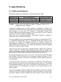
3.1. Cable specifications ....................................................................... 47
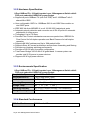
3.2. Technical Specifications ................................................................ 49
3.2.1. Software Specification ....................................................... 49
3.2.2. Hardware Specification ..................................................... 50
3.2.3. Environments Specification ............................................... 50
3.2.4. Standard Conformance ..................................................... 50
Warranty statement.................................................................... 51
Layer 2/2+ Management Switch Series
4
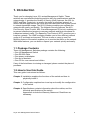
1. Introduction
Thank you for choosing Layer 2/2+ series Management Switch. These
switches are cost-effective switching solution idea for small business and the
network edge. It provides the Quality of Service (QoS) features, like 802.1p,
DSCP and Rate Control etc, to ensure the traffic is prioritized properly to
deliver real-time applications like voice and video and also have a good control
in network bandwidth usage. The 802.1Q feature enables you separate the
network traffic easily and quickly. The Network Security features, like ACL,
Port Security, Storm Control, 802.1X and Management IP List etc, enables you
to prevent unauthorized access to company network and block intentional or
inadvertent network traffic. The Spanning Tree Protocol (STP) provides you a
loop-free network. The IGMP snooping enables you to have efficient network
usage in IP multicast environment. The one-to-one or many-to-one Port
Mirroring feature of the switch enables you to monitor the traffic on the network.
With these features, you can build or expand your network quickly and easily.
1.1. Package Contents
These L2 Management Switches package contains the following:
> One L2 Management Switch
> One RS-232 cable
> One power cord/adapter
> One set of brackets.
> One CD for user manual and utilities.
If any of the listed items is missing or damaged, please contact the place of
purchase.
1.2. How to Use this Guide
This user guide is structured as follows:
Chapter 2, Installation explains the functions of the switch and how to
physically install it.
Chapter 3, Configuration explains how to set up and modify the configuration
of the switch.
Chapter 4, Specifications contains information about the cables, and the
technical specifications of the switch.
Appendices include the Warranty Statement. Read them as
necessary.
Layer 2/2+ Management Switch Series
5
2. Installation
This chapter describes the function of the management switch components
and shows how to install it on the desktop or shelf. Basic knowledge of
networking is assumed. Read this chapter completely before continuing.
2.1. Product Description Overview
These product is a L2 management switch which supports 802.1Q VLAN, QoS,
802.1d / 1w/ 1s Spanning Tree Protocol, 802.1x, Port Security, Port Mirroring,
IGMP Snooping, SNTP, Storm Control, Rate Control, SNMP etc. features.
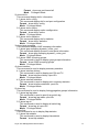
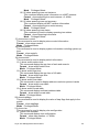
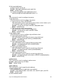
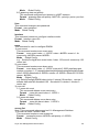
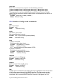
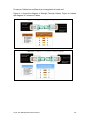
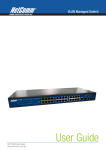
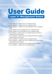
2.2. Switch Front and Rear Panel
8-Port 100BaseTX + 2 Gigabit combo Layer 2 Management Switch with 8 PSE port
embedded 100W PoE power budget
The front panel of this switch has 8 10/100 Mbps copper ports at the left with 2
shared Gigabit SFP slots at the right. The product name indicates at the top on
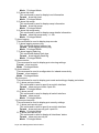
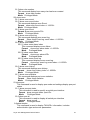
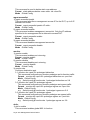
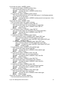
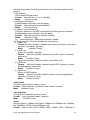
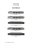
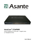
the right. Figure 2.2.6a shows a front panel of the switch. The rear panel has a
power and console connector, and Figure 2.2.6b shows a rear panel of the
switch. Table 2.2.6c shows the port function of the switch.
Figure 2.2.6a Front Panel
Figure 2.2.6b Rear Panel
Power
Table 2.2.6c Port Function
Port
Power
Function
This is where you connect the DC power adapter.
Layer 2/2+ Management Switch Series
6
2.3. LED Function
This section explains the definition of the Switch’s LEDs on the front panel.
8-Port 100BaseTX + 2 Gigabit combo Layer 2 Management Switch with 8 PSE port
embedded 100W PoE power budget:
PWR (Green) LED lights up, it shows the system is powered up.
Link/Act (Green) LED lights up, it indicates a successful connection of that
port is established. Otherwise, it indicates the link is off or
no-link detected of that port. When the LED blinks, it
indicates the port is activating and transmitting data;
PoE (Amber) LED lights up only when the corresponding port supply power.
2.4. Reset Button
There is a Reset button on the front panel, which has two functionalities:
a) To restore switch configuration to factory defaults
Press the Reset button for more than 10 seconds, switch configuration will
be restored to factory defaults and then reboots.
b) To reboot switch
Press the Reset button for less than 10 seconds, switch will reboot. Please
note, you will lose unsaved change when doing this.
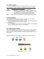
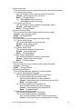
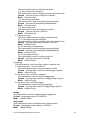
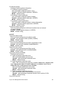
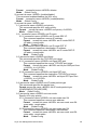
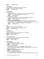
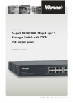
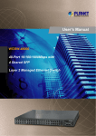
2.5. Installing the Switch
This section describes how to install and make connection to your Managed
Switch. The following diagram shows the a typical network configuration,
Figure shows the network configuration for L2/L2+ Management Switch with
PoE function.
Figure 2.5.2 Network Configuration for L2 Management Switch with PoE
Layer 2/2+ Management Switch Series
7
Read and perform the following procedures to install the switch,
Pre-Installation Considerations
Gigabit Considerations:
If you will use the switch for Gigabit applications, keep in mind that the
maximum UTP cabling length of Category 5e cable is 328 feet (100 meters).
Positioning the switch:
When choosing a location for the switch, observe the following guidelines:
Keep enough ventilation space between the switch and the surrounding
objects.
Keep cabling away from sources of electrical noise, power lines, and
fluorescent lighting fixtures.
Do not stack free-standing switch more than four units high.
Desktop or Shelf Mounting
To install the switch on a desktop or shelf, simply complete the following steps:
Step 1 Place the switch on a desktop or shelf near an AC power source.
Step 2 Keep enough ventilation space between the switch and the surrounding
objects.
Note: When choosing a location, keep in mind the environmental restrictions
discussed in Chapter 4, Specifications.
Step 3 Connect the switch to network devices.
A. Connect one end of a standard network cable to the RJ-45 ports on the front
of the switch.
B. Connect the other end of the cable to the network devices such as printer
servers, workstations or routers.
Note: It is recommended to use the UTP Category 5e network cabling with
RJ-45 tips for the network connection. For more information, please
see the Cable Specifications in Chapter 4, Specifications.
Step 4 Supply power to the switch.
A. Connect one end of the power cable to the switch.
B. Connect the power cube end of the power cable to a standard wall outlet.
2.6. Rack- Mount Placement
Before mounting the Switch, please read the following instructions carefully,
A) Elevated Operating Ambient - If installed in a closed or multi-unit rack
assembly, the operating ambient temperature of the rack environment may
be greater than room ambient. Therefore, consideration should be given to
installing the equipment in an environment compatible with the maximum
ambient temperature (Tma) specified by the manufacturer.
B) Reduced Air Flow - Installation of the equipment in a rack should be such
that the amount of air flow required for safe operation of the equipment is
not compromised.
C) Mechanical Loading - Mounting of the equipment in the rack should be such
Layer 2/2+ Management Switch Series
8
that a hazardous condition is not achieved due to uneven mechanical
loading.
D) Circuit Overloading - Consideration should be given to the connection of the
equipment to the supply circuit and the effect that overloading of the circuits
might have on overcurrent protection and supply wiring. Appropriate
consideration of equipment nameplate ratings should be used when
addressing this concern.
E) Reliable Earthing - Reliable earthing of rack-mounted equipment should be
maintained. Particular attention should be given to supply connections
other than direct connections to the branch circuit (e.g. use of power
strips)."
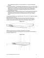
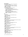
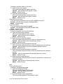
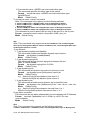
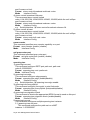
To mount the Switch in any standard-sized, 19-inch wide, 1U high rack, please
follow these instructions:
Place the Switch on a hard flat surface with the front panel facing you.
Attach a rack–mount bracket to one side of the Switch with the supplied
screws. Then attach the other bracket to the other side. (Figure 2.6.1)
Figure 2.6.1
Make sure the brackets are properly attached to the Switch.
Use the appropriate screws (not included) to securely attach the brackets to
your rack. (Figure 2.6.2)
Figure 2.6.2
Layer 2/2+ Management Switch Series
9
Configuration
The configuration programs are supplied with these Layer 2 Management
Switches. Unlike the unmanaged switch (dumb switch), the switch performs
"management" functions that make the switch operate more effectively. This
Chapter will describe the use of the switch Management Configuration
program.
2.7. Preparing for configuration
Layer 2 Management Switch offers a console CLI interface for switch
configuration and management. Users can use this interface to perform the
activities such as configuring DHCP, ARP, assigning IP address and
upgrading firmware etc.
There are four methods to manage your switch:
Local Console Management
You can manage the switch locally by connecting the switch to a PC or
workstation with terminal emulation software using the serial port.
Remote Console Management
You can manage the switch by having a remote host establish a Telnet
connection to the switch via an Ethernet or modem link.
SNMP Management
You can manage the switch across a LAN using an SNMP Network
Management Station with a graphical user interface. Note that to use this
management method, your network must use the IP protocol and your switch
must be configured on the Network with a proper IP address. You may use any
of the following method to manage the switch.
Web-Browser
You can manage the switch through a web connection by connecting to the
switch’s IP address using your web browser.
This User Guide provides instructions on how to configure the switch using the
console interface. Read the following sections to start up!
2.7.1. Connecting a PC or Terminal to the RS-232 Port
When you are ready to configure the Management Function of the switch,
make sure you have connected the supplied RS-232 serial cable to the
RS-232 port at the front panel of your switch and your PC.
2.7.2. Terminal Emulation Setup Program
Run a terminal emulation program with the following setting.
Emulation: VT-100 compatible
Baud per second: 38400
Data bits: 8
Parity: None
Stop bits: 1
Layer 2/2+ Management Switch Series
10
Flow Control: None
2.7.3. Logging on to the switch
Enter the factory default user name “admin” with no password when logging
on to the switch. The password is set to be empty. If you can enter “?” on the
command line screen, it will display all items so that you can configure by your
requirements.
2.8. Web-based configuration
The Switch provides a Web-based interface for configuring and managing the
Switch. This interface allows you to access the switch using the Web browser
of your choice. This chapter describes how to use the switch’s Web browser
interface to con-figure and manage the switch.
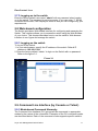
2.8.1. Logging on the switch
To log on to the Switch:
1. In your web browser, specify the IP address of the switch. Default IP
address is 192.168.1.254.
2. Enter the factory default “admin “to login on the Switch with no password.
Refer to the figure 3-1.
Figure 3-1
2.9. Command Line Interface (by Console or Telnet)
2.9.1. Mode-based Command Hierarchy
The Command Line Interface (CLI) groups all the commands in appropriate
modes by the nature of the commands. Examples of the CLI command modes
are described below. Each of the command modes supports specific switch’s
Layer 2/2+ Management Switch Series
11
commands.
The CLI Command Modes table captures the command modes, the prompts
visible in that mode and the exit method from that mode.
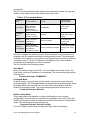
Table 1 CLI Command Modes
Command
Mode
User Mode
Privileged
Mode
Global
Config Mode
Interface
Config Mode
Access Method
This is the first
level of access.
Perform basic
tasks and list
system information.
From the User
Mode, enter the
enable command.
From the Privileged
Mode, enter the
configuration
command.
From the Global
Config mode, enter
the interface
<port#> command.
Prompt
Exit or Access
Previous Mode
COMMAND>
Enter Logout
command
Switch#
Switch (Config)#
Switch (Interface <port#>)#
To exit to the User
Mode, enter exit or
Logout.
To exit to the
Privileged Mode,
enter the exit
command.
To exit to the Global
Config mode, enter
exit.
The CLI is divided into various modes. The commands in one mode are not
available until the operator switches to that particular mode. The commands
available to the operator at any point in time depend upon the mode. Entering
a question mark (?) at the CLI prompt, and displays a list of the available
commands and descriptions of the commands.
The CLI provides the following modes:
User Mode
When the operator logs into the CLI, the User Mode is the initial mode. The
User Mode contains a limited set of commands. The command prompt shown
at this level is:
Command Prompt: COMMAND>
Privileged Mode
To have access to the full suite of commands, the operator must enter the
Privileged Mode. The Privileged Mode requires password authentication. From
Privileged Mode, the operator can issue any Exec command to enter the
Global Configuration mode. The command prompt shown at this level is:
Command Prompt: Switch#
Global Config Mode
This mode permits the operator to make modifications to the running
configuration. General setup commands are grouped in this mode. From the
Global Configuration mode, the operator can enter the Interface Configuration
mode. The command prompt at this level is:
Command Prompt: Switch(Config)#
From the Global Config mode, the operator may enter the following
Layer 2/2+ Management Switch Series
12
configuration modes:
Interface Config Mode
Many features are enabled for a particular interface. The Interface commands
enable or modify the operation of an interface. In this mode, a physical port is
set up for a specific logical connection operation. The command prompt at this
level is:
Command Prompt: Switch(Interface <port#>)#
2.9.2. User Mode commands
help
This command displays help information
Format help
Mode User Mode
?
This command displays help information
Format help
Mode User Mode
logout
This command is used to exit from the telnet
Format logout
Mode User Mode
ping
This command sends echo messages.
Format ping <A.B.C.D>
Mode User Mode
show
1) show port
This command displays port status.
Format show port {<port#> | all}
Mode User Mode
2) show network
This command displays switch IP configuration
Format show network
Mode User Mode
3) show system
This command displays system information.
Format show system
Mode User Mode
4) show port statistics
This command displays port statistics.
Format show port statistics {<port#> | all}
Mode User Mode
enable
Layer 2/2+ Management Switch Series
13
Enter to the Privileged Mode
Format enable
Mode User Mode
2.9.3. Privileged Mode commands
cable-diag
This command is used to proceed cable diagnostic
Format cable-diag port <port ID>
Mode Privileged Mode
e.g. Switch#cable-diag port 1
clear
1) clear arl
This command is used to clear ARL table entries
Format clear arl
Mode Privileged Mode
2) clear arl dynamic
This command is used to Clear dynamic arl table entries
Format clear arl dynamic
Mode Privileged Mode
3) clear arl static
This command is used to clear static arl table entries
Format clear arl static mac <mac-addr>
Mode Privileged Mode
4) clear config
This command is used to restore switch factory default configuration
Format clear config
Mode Privileged Mode
5) clear counters
This command is used to clear RMON statistics for entire switch
Format clear counters
Mode Privileged Mode
6) clear igmpsnooping
This command is used to restore igmpsnooping configuration to factory
default
Format clear igmpsnooping
Mode Privileged Mode
7) clear static-mcast
This command is used to clear static multicast groups
Format clear static-mcast
Mode Privileged Mode
8) clear pass
This command is used to restore administrator’s password to factory default
Format clear pass
Mode Privileged Mode
9) clear lacp
This command is used to restore LAG and LACP configuration to factory
Layer 2/2+ Management Switch Series
14
default
Format clear lacp
Mode Privileged Mode
10) clear logs
This command is used to clear memory/flash logs
Format clear logs
Mode Privileged Mode
11) clear vlan
This command is used to delete all VLAN groups
Format clear vlan
Mode Privileged Mode
configuration
Enter into Global Configuration mode
Format configuration
Mode Privileged Mode
copy
This command is used to upload file from switch to host, or download file to
switch from host
1) copy nvram_config
This command is used to backup switch configuration
Format copy nvram_config tftp <A.B.C.D> file <filename>
Mode Privileged Mode
e.g. Switch#copy nvram_config tftp 192.168.1.100 file switch_configuration
2) copy system_image
This command is used to backup switch runtime image
Format copy system_image tftp <A.B.C.D> <filename>
Mode Privileged Mode
e.g.
Switch#copy system_image tftp 192.168.1.100 image_file
3) copy tftp
This command is used to upload configuration or runtime image
Format copy tftp <A.B.C.D> file <filename> {nvram_config |
system_image}
Mode Privileged Mode
e.g.
Switch#copy tftp 192.168.1.100 file switch_configuration nvram_config
Switch#copy tftp 192.168.1.100 file runtime_code system_image
exit
This command is used to exit current shell
Format exit
Mode Privileged Mode
help
This command displays help information
Format help
Mode Privileged Mode
logout
This command is used to exit current shell
Format logout
Layer 2/2+ Management Switch Series
15
Mode Privileged Mode
ping
This command is used to proceed ping destination host
Format ping <A.B.C.D>
Mode Privileged Mode
reload
This command is used to reboot system
Format reload
Mode Privileged Mode
save
This command is used to save configuration
Format save
Mode Privileged Mode
show
This command is used to show configured data
1) show qos
This command display class of service information
1.1) show qos cos
This command display the cos mapping
Format show qos cos
Mode Privileged Mode
1.2) show qos queue-settings
This command display the queue-settings mapping
Format show qos queue-settings
Mode Privileged Mode
1. 3) show qos advanced
This command display qos advanced mode information
1.3.1) show qos advanced mode
This command display mode of qos
Format show qos advanced mode
Mode Privileged Mode
1.3.2) show qos advanced dscp
This command display qos dscp mapping
Format show qos advanced dscp
Mode Privileged Mode
1.3.3) show qos advanced ip-precedence
This command display qos ip precedence mapping
Format show qos advanced ip-precedence
Mode Privileged Mode
1.4) show qos port-based
This command is used to display class of service information
1.4.1) show qos port-based port
This command display class of service information
Format show qos port-based port <port-ID>
Mode Privileged Mode
1.4.2) show qos port-based all
This command display all switch interfaces’ cos settings
Layer 2/2+ Management Switch Series
16
Format show qos port-based all
Mode Privileged Mode
2) show dot1x
This command display dot1x information
2.1) show dot1x config
This command display dot1x and port configuration
Format show dot1x config
Mode Privileged Mode
2.2) show dot1x radius
This command display radius configuration
Format show dot1x radius
Mode Privileged Mode
2.3) show dot1x statistics
This command display dot1x statistics
Format show dot1x statistics
Mode Privileged Mode
3) show igmp snooping
This command display IGMP snooping information
3.1) show igmp snooping dynamic_router_port
This command display dynamic router ports information
Format show igmp snooping dynamic_router_port
Mode Privileged Mode
3.2) show IGMP snooping groups
This command is used to display igmp groups information
Format show IGMP snooping groups
Mode Privileged Mode
4) show interface
This command is used to display summary statistics
4.1) show interface history
This command is used to display port RX and TX
Format show interface history <port-ID>
Mode Privileged Mode
4.2) show interface statistics
This command is used to display port summary statistics
Format show interface statistics <port-ID>
Mode Privileged Mode
5) show lag
This command is used to display link aggregation groups information
5.1) show lag lag-index
This command is used to specify an switch lag
Format show lag lag-index <port-ID>
Mode Privileged Mode
5.2) show lag all
This command is used to display all switch lag
Format show lag all <port-ID>
Mode Privileged Mode
6) show lldp
This command is use to display lldp statistics
6.1) show lldp statistic
This command is used to display lldp statistic
Format show lldp statistic
Layer 2/2+ Management Switch Series
17
Mode Privileged Mode
6.2) show lldp local
This command is used to display local information
Format show lldp local
Mode Privileged Mode
6.3) show lldp msap
This command is used to display msap information
Format show lldp msap
Mode Privileged Mode
6.4) show lldp msap-entry
This command is used to display msap details information
Format show lldp msap-entry <1..26>
Mode Privileged Mode
7) show logging
This command is used to display trap records
7.1) show logging memory-log
This command display memory log
Format show logging memory-log
Mode Privileged Mode
7.2) show logging flash-log
This command display flash logs
Format show logging flash-log
Mode Privileged Mode
8) show monitor
This command is used to display port mirroring settings
Format show monitor
Mode Privileged Mode
9) show network
This command is used to configuration for inband connectivity
Format show network
Mode Privileged Mode
10) show port
This command is used to display port mode and settings, display port status
10.1) show port port-index
This command is used to specify an switch interface
Format show port port-index <port-ID>
Mode Privileged Mode
10.2) show port all
This command is used to display all switch interface
Format show port all
Mode Privileged Mode
11) show port-security
This command is used to display port security settings
11.1) show port-security port
This command is used to specify an switch interface
Format show port-security port <port-ID>
Mode Privileged Mode
11.2) show port-security all
This command is used to display all interfaces’ status
Format show port-security all
Mode Privileged Mode
Layer 2/2+ Management Switch Series
18
12) show rate-limit
This command is used to ingress and egress rate limit information
12.1) show rate-limit port
This command is used to specify an switch interface
Format show rate-limit port <port-ID>
Mode Privileged Mode
e.g. Switch#Show rate-limit port 1
Switch#Show rate-limit port g1
12.2) show rate-limit all
This command is used to display all interfaces’ status
Format show Rate-Limit all
Mode Privileged Mode
13) show running-config
This command is used to display switch running config
Format show running-config
Mode Privileged Mode
14) show snmp
This command is used to display all snmp config
14.1) show snmp groups
This command display all snmp groups
Format show snmp groups
Mode Privileged Mode
14.2) show snmp users
This command display all snmp users
Format show snmp users
Mode Privileged Mode
3) show snmp communities
This command display all snmp communities
Format show snmp communities
Mode Privileged Mode
15) show sntp
This command is used to display switch sntp information
Format show sntp
Mode Privileged Mode
16) show spanning-tree
This command displays Spanning Tree information
16.1) show spanning-tree interface
This command displays RSTP ports information
16.1.1) show spanning-tree interface port
This command specify an switch interface
Format show spanning-tree interface port<port-ID>
Mode Privileged Mode
16.1.2) show spanning-tree interface all
This command display all switch interface
Format show spanning-tree interface all
Mode Privileged Mode
16.2) show spanning-tree mst
This command display MST information
16.2.1) show spanning-tree mst detailed
This command display a MST instance information
Format show spanning-tree mst detailed <0..4094>
Layer 2/2+ Management Switch Series
19
Mode Privileged Mode
16.2.2) show spanning-tree mst instance
This command display ports information on a MST instance
Format show spanning-tree mst instance <0..4094>
Mode Privileged Mode
16.2.3) show spanning-tree mst summary
This command display all MST instance information
Format show spanning-tree mst summary
Mode Privileged Mode
16.2.4) show spanning-tree status
This command is used to display spanning-tree status
Format show Spanning-tree status
Mode Privileged Mode
17) show storm-control
This command is used to display storm-control information
Format show storm-control
Mode Privileged Mode
18) show sysinfo
This command is used to display system information including system up
time
Format show sysinfo
Mode Privileged Mode
19) show switch
This command is used to display switch information
19.1) show switch admin-time
This command display the age time of web and console
Format show switch admin-time
Mode Privileged Mode
19.2) show switch age-time
This command display the age time of L2 table
Format show switch age-time
Mode Privileged Mode
19.3) show switch mac-table
This command is used to display address resolution protocol cache
Format show switch mac-table
Mode Privileged Mode
19.4) show switch mcast-table
This command display multicast address table
Format show switch mcast-table
Mode Privileged Mode
20) show trapflags
This command is used to display the value of trap flags that apply to the
switch
Format show trapflags
Mode Privileged Mode
21) show vlan
This command is used to display vlan configuration
21.1)show vlan member
This command display vlan configuration
Format show vlan member <1..4094>
Mode Privileged Mode
Layer 2/2+ Management Switch Series
20
21.2)show vlan number
This command display how many vlan has been created
Format show vlan number
Mode Privileged Mode
22) show rmon
22.1) show rmon event
22.2) show rmon event Index
This command displays rmon Event.
Format show rmon event index <1..65535>
Mode Privileged Mode
22.3) show rmon event
Format Show rmon event<CR>
Mode
Privileged Mode
22.4) show rmon event log
This command displays rmon event log.
Format Show rmon Event log event index <1..65535>
Mode
Privileged Mode
22.5) show rmon alarm
22.5.1) show rmon alarm index
This command displays rmon Alarm.
Format show rmon alarm index <1..65535>
Mode
Privileged Mode
22.5.2) show rmon alarm
Format show rmon alarm<CR>
Mode Privileged Mode
22.5.3) show rmon event log
This command displays rmon event log.
Format show rmon event log event index <1..65535>
Mode
Privileged Mode
22.6) show rmon history
This command displays rmon history.
Format show rmon history index <1..65535>
Mode
Privileged Mode
22.7) show rmon statistics
This command displays port rmon statistics.
Format Show rmon statistics
Mode
Privileged Mode
23 )show poe
This command is used to display poe mode and settings,display poe port
status
23.1) show poe port-index
This command is used to specify an switch poe interface
Format show poe port-index <port-ID>
Mode
Privileged Mode
23.2)show poe all
This command is used to display all switch poe interface
Format show poe all
Mode
Privileged Mode
24)show tacplus
This command is used to display TACACS+ information, includes
authentication type and server parameters.
Layer 2/2+ Management Switch Series
21
Format show tacplus
Mode
Privileged Mode
telnet
This command telnet the other host.
Format telnet <A.B.C.D>
Mode Privileged Mode
2.9.4. Global Config mode commands
exit
This command is used to exit current shell
Format exit
Mode Global Config
vlan
This command is used to configure vlan
1) vlan add
This command is used to create a new vlan
1.1) vlan add number
This command enter a vlan ID
Format vlan add number <vlan-ID>
Mode Global Config
1.2) vlan add range
This command enter a range of vlan ID
Format vlan add range from < vlan-ID > to <vlan-ID>
Mode Global Config
2) vlan delete
This command remove a existed vlan
Format vlan delete <vlan-ID>
Mode Global Config
3) vlan ingress
This command performs ingress vlan source port membership check
3.1) vlan ingress forward
The command is used to forward frame but don’t learn SA into ARL table
Format vlan ingress forward
Mode Global Config
3.2) vlan ingress drop
This command is used to drop frames violation vid
Format vlan ingress drop
Mode Global Config
3.3) vlan ingress bypass
This command is used to forward frame and learn SA into ARL table
Format vlan ingress bypass
Mode Global Config
4) vlan port
This command is used to configure 802.1Q port parameters for vlans
4.1) vlan port all
Layer 2/2+ Management Switch Series
22
This command is used to configure all ports
1.1) vlan port all port-configure
This command is used to configure ports in a specific vlan
Format vlan port all port configure <vlan-ID>
Mode Global Config
1.2) vlan port all protected
This command is used to configure protected ports
Format vlan port all protected {enable|disable}
Mode Global Config
1.3) vlan port all pvid
This command is used to configure port pvid
Format vlan port all pvid <vlan-ID>
Mode Global Config
4.2) vlan port ports
This command is used to configure multiple ports
4.2.1) vlan port ports port-configure
This command is used to configure ports in a specific vlan
Format vlan port ports port-configure <vlan-ID>
Mode Global Config
4.2.2) vlan port ports protected
This command is used to configure protected ports
Format vlan port ports protected {enable|disable}
Mode Global Config
4.2.3) vlan port ports pvid
This command is used to configure port vid
Format vlan port ports pvid < vlan-ID>
Mode Global Config
5) vlan lag
This command is used to configure lag to a special vlan
5.1) vlan lag vlan < vlan-id> exclude
This command is used to remove lag from a vlan
Format vlan lag vlan < vlan-ID> exclude lags <lag-ID>
Mode Global Config
5.2) vlan lag vlan <vlan-ID> untagged
This command is used to set to untagged lag.
Format vlan lag vlan <vlan-ID> untagged lags <lag-ID>
Mode Global Config
5.3) vlan lag vlan <vlan-ID> tagged
This command is used to set to tagged lag.
Format vlan lag vlan <vlan-ID> tagged lags <lag-ID>
Mode Global Config
bridge
This command is used to configure switch aging time
Format bridge aging-time <0-1048575>
Mode Global Config
lacp-syspri
This command is used to configure lacp system priority
Format lacp-syspri system-priority <0-65535>
Mode Global Config
Layer 2/2+ Management Switch Series
23
link-aggregation
This command is used to configure link aggregation
1) link-aggregation addport
This command is used to configure LAG groups
Format Link Aggregation addport lag <LAG-ID>
Mode Global Config
2) link aggregation delport
This command remove ports from LAG
2.1) Link Aggregation delport all
This command remove all ports from a LAG
Format link-aggregation-delport all lag <LAG-ID>
Mode Global Config
2.2) link aggregation delport lag
This command remove specify LAG group
Format link aggregation delport lag <LAG-ID>
Mode Global Config
lldp
1) lldp enable
This command is used to enable lldp functions
Format lldp enable
Mode Global Config
2) lldp disable
This command is used to disable lldp functions
Format lldp disable
Mode Global Config
3) lldp adv-interval
This command is used to specify advertised interval in seconds
Format lldp adv-interval <5-32768>
Mode Global Config
4) lldp fast-startcnt
This command is used to specify fast-start count
Format lldp fast-startcnt <1-10>
Mode Global Config
5) lldp hold
This command is used to specify hold value
Format lldp hold <2-10>
Mode Global Config
6) lldp notify-interval
This command is used to specify notification interval in seconds
Format lldp notify-interval <5-3600>
Mode Global Config
7) lldp reinit-delay
This command is used to specify re-initialization delay in seconds
Format lldp reinit-delay <1-10>
Mode Global Config
8) lldp tx-delay
Transmit Delay in seconds
Format lldp tx-delay <1-8192>
Mode Global Config
Layer 2/2+ Management Switch Series
24
9) lldp mgmt-addrtxport
A range of ports can be set.
Format lldp mgmt-addrtxport ports <port list>
Mode Global Config
e.g. switch(config)# lldp mgmt-addrtxport ports 1
switch(config)# lldp mgmt-addrtxport ports 1-4
log
This command is used to configure log server
1) log log-server
This command is used to configure log server
1.1) log log-server name <WORD>add
This command is used to specify log server name, enter a name, up to
12 characters, add a log server IP address
Format log log-server name <WORD> add ipaddr word
Mode Global Config
1.2) log log-server name <word> delete
This command is used to delete a log server
Format log log-server name <WORD> delete
Mode Global Config
2) log logging-target
This command is used to configure log notification level
2.1) log logging-target memory
This command is used to specify memory log notify-level
Format log logging-target memory {enable|disable}
Mode Global Config
2.2) log logging-target flash
This command is used to specify flash log notify-level
Format log logging-target flash {enable|disable}
Mode Privileged Mode
2.3) log logging-target console
This command is used to specify console log notify-level
Format log logging-target console {enable|disable}
Mode Global Config
2.4) log logging-target server
This command is used to specify console log notify-level
Format log logging-target server name <WORD> {enable|disable}
Mode Global Config
radius-server
This command is used to configure radius server
Format radius-server ip <IP addr>
Mode Global Config
static-address
This command is used to specify static address
1) static-address add
This command is used to add static mac address
Format static-address add <mac addr> vid <vlan-ID> port <port-ID>
Mode Global Config
2) static-address delete
Layer 2/2+ Management Switch Series
25
This command is used to delete static mac address
Format static-address delete <mac addr> vid <vlan-ID>
Mode Global Config
mgmt-accesslist
1) mgmt-accesslist ipaddr
This command specifies a management access IP for the DUT, up to 8 IP
address can be set.
Format mgmt-accesslist ipaddr <IP addr>
Mode Global Config
2) mgmt-accesslist enable
This command enables management access list. Only the IP address
specified in the management list is allowed to access DUT.
Format mgmt-accesslist enable
Mode Global Config
3) mgmt-accesslist disable
This command disables management access list.
Format mgmt-accesslist disable
Mode Global Config
monitor
1) monitor enable
This command enables port mirroring.
Format monitor enable
Mode Global Config
2) monitor disable
This command disables port mirroring.
Format monitor disable
Mode Global Config
3) monitor des
Configure destination port.
3.1) monitor des <port-ID> probetype bidirection
This command configures port monitor probetype as bi-direction traffic.
Format monitor des <port-ID> probetype bidirection src <port list>
Mode Global Config
e.g. Switch(config)# monitor des 1 probetype bidirection src 2-8
3.2) monitor des <port-ID> probetype ingress
This command configures port monitor probetype as ingress traffic.
Format monitor des <port-ID> probetype ingress src <port list>
Mode Global Config
e.g. Switch(config)# monitor des 1 probetype ingress src 2-8
3.3) monitor des <port-ID> probetype egress
This command configures port monitor probetype as egress traffic.
Format monitor des <port-ID> probetype egress src <port list>
Mode Global Config
e.g. Switch(config)# monitor des 1 probetype egress src 2-8
dot1x
1) dot1x enable
This command enables global 802.1x function.
Layer 2/2+ Management Switch Series
26
Format dot1x enable
Mode Global Config
2) dot1x disable
This command disables global 802.1x function.
Format dot1x disable
Mode Global Config
3) dot1x port-control
Configure port auto-authentication mode.
3.1) dot1x port-control enable
This command set auto-authorized on a list of ports.
Format dot1x port-control enable port <port list>
Mode Global Config
3.2) dot1x port-control disable
This command set force authorized on a list of ports.
Format dot1x port-control disable port <port list>
Mode Global Config
e.g. Switch(config)# dot1x port-control disable port 1-4
network
1) network mgmt-vlan
This command changes management vlan.
Format network mgmt-vlan <vlan-ID>
Mode Global Config
2) network parms
This command configures static IP address of the switch.
Format network parms <IP addr> <subnet mask> <gateway>
Mode Global Config
3) network protocol
This command configure switch dhcp client.
Format network protocol {dhcp|none}
Mode Global Config
4) network dhcp-relay
Configure switch dhcp relay functions.
4.1) network dhcp-relay mode
This command configures dhcp relay mode.
Format network dhcp-relay mode {enable|disable}
Mode Global Config
4.2) network dhcp-relay server
This command configures dhcp-relay server ip-address.
Format network dhcp-relay server <A.B.C.D>
Mode Global Config
4.3) network dhcp-relay vlan
Configure dhcp-relay option-82 vlan information.
3.1) network dhcp-relay vlan <vlan-ID> add
This command enters a vlan which will be enable DHCP-relay option82.
Format network dhcp-relay vlan <vlan-ID> add
Mode Global Config
3.2) network dhcp-relay vlan <vlan-ID> remove
This command enters a vlan which will be disable dhcp-relay option82.
Format network dhcp-relay vlan <vlan-ID> remove
Mode Global Config
Layer 2/2+ Management Switch Series
27
5) network sysinfo
Configure switch system information.
5.1) Network sysinfo sysname
This command configures system name.
Format network sysinfo sysname <WORD>
Mode Global Config
5.2) network sysinfo syslocate
This command configures system location.
Format network sysinfo syslocate <WORD>
Mode Global Config
5.3) network sysinfo syscontact
This command configures system contact information.
Format network sysinfo syscontact <WORD>
Mode Global Config
6) network admin-timeout
This command configures web/console admin time out interval.
‘0’ means disable.
Format network admin-timeout <0-65535>
Mode Global Config
port-all
1) port-all admin-mode
This command configures ports admin mode.
Format port-all admin-mode {enable | disable}
Mode Global Config
2) port-all auto-negotiate
This command configures ports auto-negotiation mode.
Format port-all auto-negotiate {enable|disable}
Mode Global Config
3) port-all flow-control
This command configures ports flow control.
Format port-all flow-control {enable|disable}
Mode Global Config
4) port-all portsec-lockmode
Configure port security.
4.1) port-all portsec-lockmode none
This command disable port security.
Format port-all portsec-lockmode none
Mode Global Config
4.2) port-all portsec-lockmode static
Note: This commands only support on 24-Port 100BaseTX + 2 Gigabit combo
Layer 2 Management Switch & 48-Port 100BaseTX + 4 1000BaseT with 2 shared
Gigabit SFP Layer 2+ Management Switch models
This command enable static lock mode.
Format port-all portsec-lockmode static
Mode Global Config
4.3) port-all portsec-lockmode dynamic
This command enable limited dynamic lock mode.
Format port-all portsec-lockmode dynamic max-entries <0-24>
Mode Global Config
5) port-all rate-limit
Layer 2/2+ Management Switch Series
28
Configure rate limit value on all ports.
5.1) port-all rate-limit egress
This command specifies egress rate limit.
Format port-all Rate-Limit egress <value>
Mode Global Config
5.2) port-all rate-limit ingress
This command specifies ingress rate limit.
Format port-all rate-limit ingress <value>
Mode Global Config
6) port-all rmon-counter
This command configures rmon counter capability on ports.
Format port-all rmon-counter {enable|disable}
Mode Global Config
7) port-all speed
This command configures ports speed.
Format port-all speed {10hd|10fd|100hd|100fd}
Mode Global Config
8) port-all storm-control
Configure all ports’ storm control settings.
8.1) port-all storm-control disable
This command disables storm control.
Format port-all Storm-Control disable
Mode Global Config
8.2) port-all storm-control broadcast
This command configures storm control for broadcast only.
Format port-all storm-control broadcast <value>
Mode Global Config
8.3) port-all storm-control broadcast-multicast
This command configures storm control for broadcast and multicast.
Format port-all Storm-Control broadcast-multicast <value>
Mode Global Config
8.4) port-all storm-control broadcast-unknown
This command configures storm control for broadcast and unknown
unicast.
Format port-all storm-control broadcast-unknown <value>
Mode Global Config
8.5) port-all storm-control all-cast
This command configures storm control for broadcast, multicast and
unknown unicast.
Format port-all Storm-Control all-cast <value>
Mode Global Config
qos
1) qos qos-advanced
Configure qos advanced mode.
1.1) qos qos-advanced DSCP
This command enables DSCP mode.
Format qos qos-advanced DSCP
Mode Global Config
1.2) qos qos-advanced ip_precedence
This command enables IP Precedence mode.
Layer 2/2+ Management Switch Series
29
Format qos qos-advanced ip_precedence
Mode Global Config
1.3) qos qos-advanced none
This command disables qos advanced mode.
Format qos qos-advanced none
Mode Global Config
2) qos cos
This command configures 802.1p priority queue mapping.
Format Qos cos priority <0-7> queue <1-4>
Mode Global Config
3) qos dscp
This command specifies dscp value to queue mapping.
Format qos dscp <0-63> queue <1-4>
Mode Global Config
4) qos port-based
This command configures port-based priority mapping.
Format qos port-based port <WORD>status {enable | disable}
Mode Global Config
5) qos scheduling
Configure qos scheduling mode.
5.1) qos scheduling strict
This command sets to strict priority.
Format qos scheduling strict
Mode Global Config
5.2) qos scheduling wrr
This command sets to Weight Round-Robin.
Format qos scheduling wrr
Mode Global Config
6) qos ip-precedence
This command configures IP precedence queue mapping.
Format qos ip-precedence <0-7> queue <1-4>
Mode Global Config
7) qos wrr
This command configures queue weight for weight round robin.
Format qos wrr weight <1-15> queue <1-4>
Mode Global Config
8) qos dscp-remark
Note: This command only supports on the following switches,
2. 24-Port 100BaseTX + 2 Gigabit combo Layer 2+ Management Switch
4. 24-Port 1000BaseT with 2 shared Gigabit SFP Layer 2+ Management Switch
5. 48-Port 1000BaseT with 4 shared Gigabit SFP Layer 2+ Management Switch
This command is used to change DSCP value if the outgoing packet is an IP
packet. Select an ACL Entry Name as the criterion and then enter New
DSCP Value as the action. Once the criterion is hit, the DSCP value will be
changed.
Format qos dscp-remark acl_entry_name <name> new_dscp_value <0-63>
Mode Global Config
set
1) set IGMP
Configure IGMP snooping.
Layer 2/2+ Management Switch Series
30
1.1) set igmp enable
This command enables igmp snooping.
Format set igmp enable
Mode Global Config
1.2) set igmp disable
This command disables IGMP snooping.
Format set igmp disable
Mode Global Config
1.3) set igmp last-memberquery
This command specifies last member query interval.
Format set igmp last-memberquery <1-200>
Mode Global Config
1.4) set igmp last-membercount
This command specifies last member count.
Format set igmp last-membercount <1-20>
Mode Global Config
1.5) set igmp query-interval
This command specifies igmp query interval<secs>.
Format set igmp query-interval <10-600>
Mode Global Config
1.6) set igmp query-resinterval
This command specifies igmp query response interval<secs>.
Format set igmp query-resinterval <0-200>
Mode Global Config
1.7) set igmp robustness
This command specifies robustness variable.
Format set igmp robustness <1-20>
Mode Global Config
1.8) set igmp router-port
This command specifies igmp router port.
Format set igmp router-port ports <port list>
Mode Global Config
e.g. Switch(config)# set igmp router-port ports 1-10
2) set igmp-querier
This command configures igmp querier.
Format set igmp-querier {enable | disable}
Mode Global Config
3) set igmp-proxy
This command configures igmp proxy.
Format set igmp-proxy {enable | disable}
Mode Global Config
4) set static-mcast
Configure static multicast.
4.1) set static-mcast name <WORD> add
This command create a multicast group.
Format set static-mcast name <WORD> add vid <vlan-ID> mac
<mac-addr>member port <port list>
Mode Global Config
4.2) set static-mcast name <WORD>delete
This command delete a static multicast group.
Format set static-mcast name <WORD>delete
Layer 2/2+ Management Switch Series
31
Mode
Global Config
snmp
1) snmp notify
This command configures snmp notification.
Format snmp notify {enable|disable}
Mode Global Config
2) snmp group
2.1) snmp group add
This command create a snmp group.
Format snmp group add <WORD>version <1-2>
Mode Global Config
2.2) snmp group delete
This command delete a snmp group.
Format snmp group delete <WORD>
Mode Global Config
3) snmp user
3.1) snmp user add
This command creates a snmp user.
Format snmp user add <user name> group <group name> version
<1-3>
Mode Global Config
3.2) snmp user delete
This command deletes a snmp user.
Format snmp user delete <WORD>
Mode Global Config
4) snmp community
4.1) snmp community add
This command creates a community.
Format snmp community add <community name> group <group
name> mgmt-ip <ip-addr>
Mode Global Config
4.2) snmp community delete
This command deletes a community.
Format snmp community delete <community name>.
Mode Global Config
5) snmp trapstation
5.1) snmp trapstation add
Create a snmp trap station.
5.1.1) snmp trapstation add <ip-addr> community <community name>
type bootup
Send trap when system reboot
Format snmp trapstation add <ip-addr> community <community
name> type bootup trap-version {1|2}
Mode Global Config
5.1.2) snmp trapstation add <ip-addr> community <community name>
type linkchange
Send trap when port link change.
Format snmp trapstation add <ip-addr> community <community
name> type linkchange trap-version {1|2}
Mode Global Config
Layer 2/2+ Management Switch Series
32
5.1.3) snmp trapstation add <ip-addr> community <community name>
type both
Send trap when system reboot or port link change.
Format snmp trapstation add <ip-addr> community <community
name> type both trap-version {1-2}
Mode Global Config
5.1.4) snmp trapstation add <ip-addr> community <community name>
type none
Send no trap.
Format snmp trapstation add <ip-addr> community <community
name> type none trap-version {1-2}
Mode Global Config
5.2) snmp trapstation delete
This command delete a trap station.
Format snmp trapstation delete <WORD>
Mode Global Config
sntp
1) sntp daylight
This command enables or disables the daylight saving configuration.
Format sntp daylight {enable|disable}
Mode Global Config
2) sntp localtime
Configure the local time.
2.1) sntp localtime enable
This command enables local time.
Format sntp localtime enable
Mode Global Config
2.2) sntp localtime localtime_date
This command sets local time.
Format sntp localtime localtime_date <year> <month> <date> <hour>
<minute> <second>
Mode Global Config
3) sntp server
3.1) sntp server enable
This command enables sntp server.
Format sntp server enable
Mode Global Config
3.2) sntp server ipaddr
This command sets sntp server IP address.
Format sntp server ipaddr <IP-addr>
Mode Global Config
3.3) sntp server polling
This command sets sntp server polling time interval.
Format sntp serve polling <0-9>
Mode Global Config
4) sntp timezone
This command sets sntp timezone.
Format sntp timezone <1-75>
Mode Global Config
Layer 2/2+ Management Switch Series
33
spanning-tree
1) spanning-tree forceversion
This command configures Spanning Tree protocol version.
1.1) spanning-tree forceversion 8021s
This command selects spanning tree type as 8021.s(multiple Spanning
Tree).
Format spanning-tree forceversion 8021s
Mode
Global Config
1.2) spanning-tree forceversion 8021w
This command selects spanning tree type as 802.1w(rapid Spanning
Tree).
Format spanning-tree forceversion 8021w
Mode Global Config
1.3) spanning-tree forceversion none
This command selects none spanning tree type.
Format spanning-tree forceversion none
Mode Global Config
2) spanning-tree configuration
This command configures MSTP region name and revision.
2.1) spanning-tree configuration name
This command configures MSTP region name (Max.32 chars).
Format spanning-tree configuration name <WORD>
Mode Global Config
2.2) spanning-tree configuration revision
This command configures revision level.
Format spanning-trees configuration revision <0-65535>
Mode
Global Config
3) spanning-tree forward-time
This configures the bridge forward delay parameter.
Format spanning-tree forward-time <4-30>
Mode Global Config
4) spanning-tree max-age
This command configures the bridge max age parameter.
Format spanning-tree max-age <6-40>
Mode Global Config
5) spanning-tree max-hops
This command configure the number of hops in a region.
Format spanning-tree max-hops <1-40>
Mode
Global Config
6) spanning-tree port
6.1) spanning-tree port all
This command specifies RSTP capability for all ports.
Format spanning-tree port all {enable |disable}
Mode
Global Config
6.2) spanning-tree port cost
This command configures RSTP port path cost.
Format spanning-tree port cost <0-200000000>
Mode
Global Config
6.3) spanning-tree port priority
This command configures RSTP port priority.
Format spanning-tree port priority <0-24>
Layer 2/2+ Management Switch Series
34
Mode
Global Config
6.4) spanning-tree port edge
This command configures STP edge .
Format spanning-tree port edge {enable|disable}
Mode
Global Config
6.5) spanning-tree port force-p2plink
This command configures force point to point link mode on ports.
Format spanning-tree port force-p2plink {auto|enable|disable}
Mode
Global Config
6.6) spanning-tree port migration-check
This command Re-checks the appropriate BPDU format to send on
ports.
Format spanning-tree port migration-check {enable|disable}
Mode Global Config
7) spanning-tree priority
This command configures RSTP bridge priority value.
Format spanning-tree priority <0-61440>
Mode Global Config
8) spanning-tree mst
Configure a multiple spanning tree instance.
8.1) spanning-tree mst instance
This command creates or removes a MST instance
8.1.1) spanning-tree mst instance add
This command creates a MST instance.
Format spanning-tree mst instance add vlan <vlan list> mstpid <MST
ID>
Mode
e.g.
Global Config
Switch(Config)# Spanning-Tree mst instance add vlan 2-5 mstpid 2
Switch(Config)# Spanning-Tree mst instance add vlan 6 mstpid 3
8.1.2) spanning-tree mst instance delete
This command removes the last MST instance.
Format spanning-tree mst instance delete
Mode
Global Config
8.2) spanning-tree mst vlan
This command adds or deletes vlan frome a MSTP instance.
8.2.1) spanning-tree mst vlan <MST ID> <vlan list> add
This command creates a MST instance.
Format spanning-tree mst vlan <MST ID> <vlan list> add
Mode
Global Config
e.g. Switch(Config)# Spanning-Tree mst vlan 3 3-5 add
8.2.2) Spanning-Tree mst vlan <MST ID> <vlan list> delete
This command deletes a vlan from a MST instance.
Format Spanning-Tree mst vlan <MST ID> < vlan list> delete
Mode Global Config
8.3) spanning-tree mst bridgepri
This command configures bridge priority for a MST instance.
Format spanning-tree mst bridgepri <MST ID> <priority>
Mode Global Config
8.4) spanning-tree mst cost
This command configures port path cost in a MST instance.
Format spanning-tree mst cost <MST ID> <path cost> ports <port list>
Layer 2/2+ Management Switch Series
35
Mode Global Config
8.5) spanning-tree mst priority
This command configures port priority in a MST instance
Format spanning-tree mst priority <MST ID> <priority> ports <port list>
Mode
Global Config
User
This command changes user password.
Format user password
Mode Global Config
Interface
This command enters into configure interface mode.
Format Interface <port-ID>
Mode Global Config
rmon
This command is used to configure RMON.
1) rmon event
This command creates rmon event entry.
Format rmon event index < 1..65535 > desc <WORD> event <1..4>
community <WORD>owner<WORD>
Mode
Global Config
e.g. Switch(Config)# rmon event index 1 desc 123 event 4 community 123
owner test
2) rmon alarm
This command creates rmon alarm entry.
Format rmon alarm index < 1..65535 >interval<0..3600>interface<port
number>counter<1..17>sample{absolute|delta}start{rasing|falling|all}rthresh
old<0..65535>fthreshold<0..65535> reindex <0..65535> feindex<0..65535>
owner< WORD>
Mode
Global Config
e.g. Switch(Config)# RMON alarm index 1 interval 10 interface counter 1
sample delta start all rthreshold 100 fthreshold 10 reindex 1 feindex 0
owner test
3) rmon del
3.1) rmon del event
This command deletes rmon event entry.
Format rmon del event index< 1..65535 >
Mode
Global Config
3.2) rmon del alarm
This command deletes rmon alarm entry.
Format
rmon del alarm index< 1..65535 >
Mode
Global Config
access list
Note: This commands only support on L2+ Management Switches.
1) access-list name <WORD> add
This command creates a new access-list.
Format access-list name <WORD> add priority <1-65535>
Mode
Global Config
Layer 2/2+ Management Switch Series
36
2) access-list name <WORD> action
2.1) access-list name <WORD> action deny
This command denies an ACL entry.
Format access-list name <WORD> action deny
Mode
Global Config
2.2) access-list name <WORD> action permit
This command permits an ACL entry and queue 1-4 will assign priority
queue when rule activated.
Format access-list name <WORD> action permit {<cr>|queue <1-4>}
Mode
Global Config
3) access-list name <WORD> clear
This command clears ACL entry contents.
3.1) access-list name <WORD> clears SRC IP
This command clears the source IP/subnet mask filter.
Format access-list name <WORD> clear SRC IP
Mode
Global Config
3.2) access-list name <WORD> clears DST IP
This command clears the destination IP/subnet mask filter.
Format
access-list name <WORD> clear DST IP
Mode
Global Config
3.3) access-list name <WORD> clear L4port
3.3.1) access-list name <WORD> clear L4port SRC port
This command clears TCP/UDP source port filter.
Format
access-list name <WORD> clear l4port SRC port
Mode
Global Config
3.3.2) access-list name <WORD> clear l4port DST port
This command clears TCP/UDP destination port filter.
Format access-list name <WORD> clear l4port DST port
Mode Global Config
3.4) access-list name <WORD> clear packet-type
This command clears packet type filter.
Format
access-list name <WORD> clear packet-type
Mode
Global Config
3.5) access-list name <WORD> clear mac SA
This command clears a source mac address.
Format Access-list name <WORD> clear mac SA
Mode
Global Config
3.6) access-list name <WORD> clear MAC DA
This command clears a destination mac address.
Format Access-list name <WORD> clear mac DA.
Mode
Global Config
3.7) access-list name <WORD> clear VID
This command clears the 802.1Q VLAN tag of packet.
Format Access-list name <WORD> clear VID
Mode Global Config
3.8) access-list name <WORD> clear ether-type
This command clears ether type filter.
Format
access-list name <WORD> clear ether-type
Mode
Global Config
4) access-list name <WORD> deletes.
This command removes the ACL entry.
Layer 2/2+ Management Switch Series
37
Format access-list name <WORD> deletes
Mode Global Config
5) access-list name <WORD> {enable|disable}
This command enables/disables the ACL entry.
Format
access-list name <WORD> {enable|disable}
Mode
Global Config
6) access-list name <WORD> set
6.1) access-list name <WORD> set priority
This command specifies ACL entry priority.
Format access-list name <WORD> set priority <0-65535>
Mode
Global Config
6.2) access-list name <WORD> set IP-mode
6.2.1) access-list name <WORD> set IP-mode SRC IP.
This command specifies a source IP address.
Format
access-list name <WORD> set IP-mode SRC IP
<IP-addr> <mask-addr>
Mode
Global Config
6.2.2) access-list name <WORD> set IP-mode DST IP
This command specifies a destination IP address.
Format access-list name <WORD> set IP-mode DSP IP
<IP-addr> <mask-addr>
Mode
Global Config
6.3) access-list name <WORD> set L4port
This command specifies the TCP/UDP port range.
6.3.1) access-list name <WORD> set l4port SRC-port
This command specifies the source TCP/UDP port range.
Format
Access-list name <WORD> set L4 port SRE-port from
<1-65535> to <1-65535>
Mode
Global Config
6.3.2) access-list name <WORD> set l4port DST-port
This command specifies the destination TCP/UDP port range.
Format
access-list name <WORD> set l4port DST-port from
<1-65535> to <1-65535>
Mode Global Config
6.4) access-list name <WORD> set IP-mode packet-type
This command specifies the packet type.
Format access-list name <WORD> set IP-mode packet-type
{ICMP|IGMP|IP|TCP|UDP|GRE}
Mode
Global Config
6.5) access-list name <WORD> set mac-mode
Specify ACL entry priority.
6.5.1) access-list name <WORD> set mac-mode mac SA
This command specifies a source mac address.
Format access-list name <WORD> set mac-mode mac SA
<mac-addr> <mask-addr>
Mode
Global Config
6.5.2) access-list name <WORD> set mac-mode mac DA
This command specifies a destination mac address.
Format access-list name <WORD> set mac-mode mac DA
<mac-addr> <mask-addr>
Mode
Global Config
Layer 2/2+ Management Switch Series
38
6.6) access-list name <WORD> set mac-mode ether-type
This command specifies the ether type of the packet.
Format access-list name <WORD> set mac-mode ether-type
{ipv4|ARP|xns}
Mode
Global Config
7) access-list name <name> set portlist
Note: This command only supports on the following switches,
2. 24-Port 100BaseTX + 2 Gigabit combo Layer 2+ Management Switch
3. 48-Port 100BaseTX + 4 1000BaseT with 2 shared Gigabit SFP Layer 2+
Management Switch
4. 24-Port 1000BaseT with 2 shared Gigabit SFP Layer 2+ Management Switch
5. 48-Port 1000BaseT with 4 shared Gigabit SFP Layer 2+ Management Switch
This command is used to specify an acl entry to be work on a list of ports.
Format access-list name <name> set portlist <LINE | port_id>
Mode Global Config
arp
Note: This commands only support on 24-Port 1000BaseT with 2 shared Gigabit
SFP Layer 2+ Management Switch / 48-Port 1000BaseT with 4 shared Gigabit SFP Layer
2+ Management Switch models.
1) arp dynamic
1.1) arp dynamic enables and disables.
This command enables and disables dynamic arp functions.
Format arp dynamic {enable|disable}
Mode
Global Config
1.2) arp dynamic aging-time
This command set arp dynamic aging-time between 0s and
999s.”0”means disable.
Format
arp dynamic aging-time <0~999>
Mode
Global Config
1.3) arp dynamic ports
This command set dynamic arp ports to trust and un-trust.
Format arp dynamic ports {trust|untrust} <port-list>
Mode
Global Config
e.g. Swtich<Config># arp dynamic ports trust 1-4
Swtich<Config># arp dynamic ports untrust 4
1.4) arp dynamic vlan
This command set add/remove dynamic arp on specified vlan.
Format
arp dynamic vlan {add|remove} from < vlan -id> to < vlan -id>
Mode
Global Config
e.g. Swtich<Config># arp dynamic vlan add from 1 to 1
Swtich<Config># arp dynamic vlan remove from 1 to 1
2) arp static command
This command set arp static address table for mac address with IP Address.
Format arp static {add|delete} vid <1~4094> ip <A.B.C.D> mac
<mac-address>
Mode
Global Config
dos
Note: This command only supports on the following switches,
3. 48-Port 100BaseTX + 4 1000BaseT with 2 shared Gigabit SFP Layer 2+ Management
Layer 2/2+ Management Switch Series
39
Switch
4. 24-Port 1000BaseT with 2 shared Gigabit SFP Layer 2+ Management Switch
5. 48-Port 1000BaseT with 4 shared Gigabit SFP Layer 2+ Management Switch
1) dos land
This command enables and disables land-type attacks prevention.
Format dos land {enable|disable}
Mode
Global Config
2) dos blat
This command enables and disables blat-type attack prevention.
Format
dos blat {enable|disable}
Mode Global Config
3) dos syn-fin
This command enables and disables SYN-fin-type attack prevention.
Format
dos syn-fin {enable|disable}
Mode
Global Config
4) dos ports
4.1) dos ports smurf
This command enables and disables Smurf-TYPR attack prevention.
Format
dos ports smurf {enable|disable}
Mode Global Config
4.2)dos ports ping-flooding
This command enables and disables ping-flooding-type attack
prevention.
Format
dos ports ping-flooding {enable|disable}
Mode Global Config
4.3)dos ports synack-flooding
This command enables and disables SYNACK -flooding -type attack
prevention. Set rate is 64 kbps or 128kbps for port lists (1, 3-5, 7-9.11)
Format
dos ports synack -flooding {enable|disable} rate {64|128}
<port-list>
Mode Global Config
e.g. Switch<Config>#dos ports synack -flooding enablerate 64 1-4
Switch<Config>#dos ports synack -flooding enablerate 64 5
tacplus
1) tacplus authen_type
This command is used to set authentication type. There are three types for
selecting: local, tacplus, localandtacplus.
Format
tacplus authen_type {local | tacplus | localandtacplus}
Mode Global Config
2) tacplus add
This command is used to add a new TACACS+ server and set server IP
address, priority, key string, authentication port and timeout for reply.
Format tacplus add server <IP_addr> priority <0-65535> key <key string>
port <auth port id> timeout <1-30>
Mode Global Config
3) tacplus del
This command is used to delete a TACACS+ server.
Format tacplus del server <IP_addr>
Mode Global Config
Layer 2/2+ Management Switch Series
40
green-eth
Note: This command only supports on the following switches,
4. 24-Port 1000BaseT with 2 shared Gigabit SFP Layer 2+ Management Switch
5. 48-Port 1000BaseT with 4 shared Gigabit SFP Layer 2+ Management Switch.
This command is used to enable/disable green Ethernet function. Enable
green Ethernet mode will reduce system power consumption when the link is
not present.
Format green-eth { enable | disable }
Mode Global Config
2.9.5. Interface Config mode commands
exit
Exit current shell
Format
exit
Mode
Interface Config
dot1x
Set 802.1x port control.
Set auto-authorized on ports
Format 802.1x port-control {enable|disable}
Mode
Interface Config
lacp
1) admin command
Configure admin key of port
Format
lacp admin <0 ..65535>
Mode
Interface Config
e.g. switch(interface g1)#lacp admin 36768
2) priority command
Configure lacp port priority
Format
lacp priority <0..65535>
Mode
Interface Config
addport
add one port to a LAG group
Format addport <LAG-ID>
Mode
Interface Config
delport
Remove a port from a LAG group
Format delport <LAG-ID>
Mode
Interface Config
lldp
An lldp agent can transmit information about the capabilities and current status
of the system associated with its MSAP identifier. The lldp agent can also
receive information about the capabilities and current status of the system
associated with a remote MSAP identifier. However, lldp agents are not
Layer 2/2+ Management Switch Series
41
provided any means of soliciting information from other lldp agents via this
protocol.
1) lldp state set
Only transmit the lldp status
Format
lldp state {tx | rx | tx_rx | disable}
Mode
Interface Config
2) configure notifications
Enable/disable notification form the agent
Format
lldp notification {enable|disable}
Mode
Interface Config
3) Configure med notifications
Configure whether or not MED notifications from the agent are enabled.
Enable/disable med notification form the agent
Format
lldp med-notification {enable | disable}
Mode
Interface Config
e.g. Switch(Interface 1)#lldp med-notification enable
4) Configures which TLVs are enabled for transmission.
4.1) basic set
Format lldp tlvs-tx {enable | disable} option basic {port-desc | sys-name |
sys-desc | sys-capa | sys-capa }
Mode
Interface Config
4.2) 8021 set
Status of local-802.1 settings
Format
lldp tlvs-tx {enable | disable} option 8021 {pvid | vlanname |
protocol-id}
Mode
Interface Config
eg.switch(interdface 1)lldp tlvs enable option 8021 pvid
4.3) 8023 set
Format
lldp tlvs-tx {enable | disable} option 8023 {mac-phy | power|
link-aggregation| frame-size}
Mode
Interface Config
4.4) MED-set
Status of MED Settings
Format
lldp tlvs-tx {enable | disable} option med-set {capabilities |
net-policy | location-id | mdi}
Mode
Interface Config
admin-mode
Configure administrative mode on a port
Format Switch(Interface 1)# admin-mode {enable | disable}
Mode
Interface Config
auto-negotiate
Configure auto-negotiate mode on a port
Format
auto-negotiate {enable | disable}
Mode
Interface Config
speed
Set port speed to 10Mbps half duplex/ 10Mbps full/ 100Mbps half/ 100Mbps
full/ 1000Mbps 100FX mode/1000base-x full .
Format
speed {10hd | 10fd | 100hd | 100fd | 1000fd | 100fx | 1000base-x}
Layer 2/2+ Management Switch Series
42
Mode
Interface Config
flow-control
This command enable/disable flow-control at port.
Format flow-control {enable | disable}
Mode
Interface Config
port-security
1) port-security
This command add or delete a static mac into mac security table.
Format port-security {add|delete} <sourcemac >
Mode
Interface Config
2) port-security lock-mode
This command disable port security or specify static lock mode.
Format port-security lock-mode {none | static}
Mode
Interface Config
3) port-security lock-mode dynamic
This command enable limited dynamic lock mode,and specify maximin
learning entries for limited dynamic lock mode.the max-entries value :0~24
Format port-security lock-mode dynamic max-entries 24
Mode
Interface Config
qos
This command specifies port-based qos.
Format qos port-based status {enable | disable}
Mode
Interface Config
rate-limit
1) rate-limit egress
This command limits egress rate, which the unit is Kbps.
Format rate-limit egress <rate>
Mode
Interface Config
2) rate-limit ingress
This command limits ingress rate, which the unit is Kbps.
Format rate-limit ingress <rate>
Mode
Interface Config
storm-control
1) Enable/disable storm control.
Format storm-control {enable | disable}
Mode
Interface Config
2) storm-control broadcast
This command storm control for broadcast only, and limited
value :0,64,256,1024,10240,65536.102400,1024000,which the unit is Kbps
and 0 means no limit.
Format storm-control broadcast <rate>
Mode
Interface Config
3) storm-control broadcast-multicast
This command storm control limited
value :0,64,256,1024,10240,65536.102400,1024000,which the unit is Kbps
Layer 2/2+ Management Switch Series
43
and 0 means no limit.
Format storm-control broadcast-multicast <rate>
Mode
Interface Config
4) storm-control broadcast-unknown
This command storm control limited
value :0,64,256,1024,10240,65536.102400,1024000,which the unit is Kbps
and 0 means no limit.
Format storm-control broadcast-unknown <rate>
Mode
Interface Config
e.g. Switch(Interface 1)# storm-control broadcast-unknown 64
5) storm-control all-cast
This command storm control limited
value :0,64,256,1024,10240,65536.102400,1024000,which the unit is Kbps
and 0 means no limit.
Format storm-control all-cast <rate>
Mode
Interface Config
rmon-counter
This command specifies rmon counter capability on a port
Format rmon-counter {enable | disable}
Mode
Interface Config
set igmp-router-port
This command specifies igmp router port .
Format set igmp-router-port {enable | disable}
Mode
Interface Config
spanning tree
1) spanning-tree cost
This command configure RSTP port path cost, path cost
value:0~200000000.
Format spanning-tree cost <pathcost>
Mode Interface Config
2) spanning-tree edge
This command configure edge property
Format spanning-tree edge {enable|disable}
Mode
Interface Config
e.g. Switch(Interface 1)# spanning-tree edge enable
3) spanning-tree force-p2plink
This command configure force point to point link mode.
Format spanning-tree force-p2plink {auto|enable|disable}
Mode
Interface Config
4) spanning-tree migration-check
This command re-checks the appropriate BPDU format to send on this port
Format spanning-tree migration-check {enable|disable}
Mode
Interface Config
5) spanning-tree mst
This command configures multiple spanning tree instance.
5.1) spanning-tree mst cost
This command configure the path cost on a MST
instance :1~200000000.
Layer 2/2+ Management Switch Series
44
Format spanning-tree mst cost <pathcost>
Mode
Interface Config
5.2) spanning-tree mst priority
This command configure the port priority on a MST instance:0~4096.
Format spanning-tree mst priority <1 4096>
Mode
Interface Config
6) spanning-tree participation
This command configures RSTP capability on a port.
Format spanning-tree participation {enable|disable}
Mode
Interface Config
7) spanning-tree priority
this command configure RSTP port priority:0~240
format spanning-tree priority <0..240>
mode
Interface Config
vlan
1) vlan participation
This command join or leave a port to a vlan.
1.1) vlan participation exclude
This command leave a vlan.
Format vlan participation exclude < vlan id>
Mode
Interface Config
1.2) vlan participation
This command join a vlan with untagged/tagged mode.
Format vlan participation {untagged |tagged}< vlan id>
Mode
Interface Config
2) vlan protected
This command configures port protected property.
Format vlan protected {enable|disable}
Mode
Interface Config
3) vlan dropnq
This command configure port drop none 802.1Q frame .
Format vlan dropnq {enable|disable}
Mode
Interface Config
4) vlan pvid
This command configure port PVID.
Format vlan pvid <pvid>
Mode
Interface Config
e.g. Switch(Interface 1)# vlan pvid 1
Interface commands
This command change another interface
Format Interface <port number>
Mode
Interface Config
e.g. Switch(Interface 1)# interface g1
poe
1) func
This command configure poe function on a port
Format poe func {enable | disable}
Layer 2/2+ Management Switch Series
45
Mode
Interface Config
2) power-pri
This command configures the power priority on switch ports to decide which
ports have priority to supply power which power devices are connected.
Legal value are low, normal, middle or high priority. If the same power
priority on the ports, the lower port index the higher power priority.
Low
Set to low priority
Normal
Set to normal priority
Middle
Set to middle priority
High
Set to high priority
Format poe power-pri level {low | normal | middle | high}
Mode
Interface Config
3)detection
This command configures detection type on a port. set to 0,1,2,3,4 or 5
0 No Detection
1 Legacy Capacitive Detection only
2
IEEE 802.3af 4-Point Detection only (Default)
3
IEEE 802.3af 4-Point followed by Legacy
4
IEEE 802.3af 2-Point only
5
IEEE 802.3af 2-Point followed by Legacy
Format poe detection type {0 | 1 | 2 | 3 | 4 | 5}
Mode
Interface Config
4)high-power
This command configures power Energy Mode on a port
on
Start High Power (Support 30W power device)
off
End High Power Mode (Support 15.4W power device)
Format poe high-power status {enable | disable}
Mode
interface Config
Layer 2/2+ Management Switch Series
46
3. Specifications
3.1. Cable specifications
Straight-Through and Crossed-Over Cable Specifications Table
Ethernet Type
Cable Requirements
10BASE-T
Category 3 or better, UTP or STP
100BASE-TX
Category 5 or better, UTP or STP
1000BASE-T
Category 5e or better, UTP or STP
Caution:
Maximum Length
328 ft (100M)
328 ft (100M)
328 ft (100M)
Please do not use telephone cables .Telephone cables do not
support Ethernet or Gigabit .
Twisted-pair cabling comes in various grades, or categories. Category 5 is
required for Fast Ethernet, and is also the most reliable and most commonly
used category. You can buy UTP Category 5 (Unshielded Twisted Pair)
Ethernet cabling in precrimped lengths, or you can crimp your own. Crimping
your own can result in faulty connections if the
RJ-45 tips are not attached properly. Precrimped Category 5 cabling is
available at most computer retail stores.
The most reliable and commonly used type of Category 5 cabling used is UTP,
or "unshielded twisted pair." STP, or "shielded twisted pair" wiring is only
necessary for network environments exposed to excessive amounts of
electromagnetic interference, or EMI. These environments include areas with
high sources of electrical power, air conditioning, generators, and radio signals.
STP is also used for wiring outdoors.
There are two types of the wiring: Straight-Through Cables and Crossover
Cables. Category 5 UTP/STP cable has eight wires inside the sheath. The
wires form four pairs. Straight-Through Cables has same pinouts at both ends
while Crossover Cables has a different pin arrangement at each end.
In a straight-through cable, wires 1,2,3,4,5,6,7 and 8 at one end of the cable
are still wires 1~8 at the other end. In a crossover cable, the wires of 1,2,3,6
are reversed so that wire 1 become 3 at the other end of the cable, 2 becomes
6, and so forth.
To determine which wire is wire 1, hold the RJ-45 cable tip with the spring clip
facing towards the ground and the end pointing away from you. The copper
wires exposed upwards to your view. The first wire on the far left is wire 1. You
can also refer to the illustrations and charts of the internal wiring on the
following page.
There are two types of cables: Straight Through Cables and Crossover Cables.
Category 5 UTP/STP cable has eight wires inside the sheath. The wires form
four pairs. Straight Through Cables has same pinouts at both ends while
Layer 2/2+ Management Switch Series
47
Crossover Cables has a different pin arrangement at each end.
Figure 4-1 shows the diagram of Straight Through Cables. Figure 4-2 shows
the diagram of Crossover Cables.
Layer 2/2+ Management Switch Series
48
3.2. Technical Specifications
3.2.1. Software Specification
8-Port 100BaseTX + 2 Gigabit combo Layer 2 Management Switch with 8
PSE port embedded 100W PoE power budget
■ Four groups (history, statistics, alarms, and events) of embedded remote
monitoring (RMON) agents for network monitoring and traffic analysis
■ Provides SNMP protocol(v1/v2c/v3) to monitor and control the switch by
using SNMP management applications such as HP Open View
■ IGMP snooping support to limit flooding of IP multicast traffic and filtering for
controlling the set of multicast groups to which hosts on a switch port can
belong
■ Supports 802.1d/1w/1s Spanning Tree Protocol for loop free installation.
■ Supports 802.1Q VLAN for assigning users to VLAN associated with
appropriate network resources, traffic patterns, and bandwidth. Up to 256
VLAN entries can be configured
Supports Management VLAN for administration to protect switch to be
attacked by client.
■ Built-in DHCP client to get IP address from DHCP server automatically
Supports SNTP to synchronize the precision time with Internet Time server.
Supports one-to-one or many-to-one Port Mirroring.
■ Supports IEEE 802.3ad Link Aggregation, up to 3 aggregation groups.
■ Supports for IEEE 802.1p/DSCP CoS scheduling for classification and
preferred high-priority voice traffic on a port-port basis
■ Per port Ingress and Egress Rate Limiting. Minimum rate is 64 Kbps,
granularity is 64 Kbps
■ Supports Static Mode and Dynamic Learning Mode for Port Security function.
Support up to 24 MAC addresses for each port.
■ Supports Protected port feature.
■ Supports 802.1X port-based authentication, and build-in RADIUS client to
co-operate with the RADIUS servers.
■ Supports broadcast, known-multicast, and unknown unicast storm control
■ Supports web-based interface for management
■ Supports CLI interface for local console or remote Telnet management
■ Supports TFTP, HTTP and X-modem protocol for firmware/configuration
upgrade or backup.
■ Supports TACACS+ login authentication.
Layer 2/2+ Management Switch Series
49
3.2.2. Hardware Specification
8-Port 100BaseTX + 2 Gigabit combo Layer 2 Management Switch with 8
PSE port embedded 100W PoE power budget
■ Supports 8 ports 100Base-TX (with PoE PSE) and 2 1000BaseT with 2
shared Mini-GBIC.
■ User configurable 100FX or 1000Base-SX/LX mini-GBIC fiber module on
mini-GBIC ports
■ IEEE 802.3ab Auto MDI/MDI-X on all 10/100/1000 twisted-pair ports
■ Automatic polarity detection and correction on all RJ-45 ports for automatic
adjustment of wiring errors
■ Throughput: Up to 5.6 Gbps.
■ Provides Flow Control mechanism ensures zero packet loss, IEEE802.3x
Flow Control for full-duplex operation and Back Pressure for half-duplex
operation
■ Supports 8K MAC address and Up to 3Mb packet buffer
■ Supports Store & Forward architecture and performs forwarding and filtering
■ Provides non-blocking switching performance
■ Provides a RS-232 port for system configuration.
■ Total Power Budget 100 W with 8 W guard band. It means system can
provide total 92 W power to power devices.
■ Supports 30 W high power devices.
3.2.3. Environments Specification
8-Port 100BaseTX + 2 Gigabit combo Layer 2 Management Switch with 8
PSE port embedded 100W PoE power budget:
H44 x W263 x D170 mm
Size (H x W x D)
1.3kg /2.0kg (45oz/ 70oz)
Weight(Net/Gross)
Power
48VDC 2.5A, 4pin DC-inlet
Operating Temp.
0
Storage Temp.
-40
Operating Humidity
20% to 85%,relative humidity, non-condensing
Storage Humidity
20% to 90%,relative humidity, non-condensing
~ 40
~ 70
(32
~ 104
(-40
)
~ 158
)
3.2.4. Standard Conformance
EMC Certification
FCC Class A, CE
Layer 2/2+ Management Switch Series
50
5. Warranty statement
We provide this limited warranty for it originally purchased the product
from us or its authorized reseller or distributor. We guarantee that equipment is
free from physical defects in workmanship and material under normal use from
the date of original retail purchase of the Hardware. If the product proves
defective during this warranty period, call our Customer Service in order to
obtain a Return Authorization number. Be sure to have a proof of purchase on
hand when calling. Return requests cannot be processed without proof of
purchase. When returning a product, mark the Return Authorization Number
clearly on the package pack and include you original proof of purchase. All
customers outside the R.O.C shall be held responsible for shipping and
handling charges.
In no event shall our liability exceed the price paid for the product from
direct, incidental or consequential damage resulting from the use of the
product, its accompanying software, or its documentation. We make no
warranty or representation, expressed, implied, or statutory, with respect to its
products or the contents or use of this documentation and all accompanying
software, and specifically disclaim its quality, performance, merchantability, or
fitness for any particular purpose. We reserve the right to revise or update its
products, software, or documentation without obligation to notify any individual
or entity.
Layer 2/2+ Management Switch Series
51