1
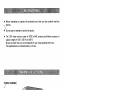
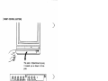
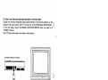
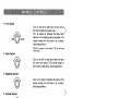
MODEL-1701
)
For Customer Use
Use::
Enter
Enter below
below the
the Model
Model No.
No. and
and
Seria
Seriall No
No.. which
which is
is located
located on
on the
the
rear
rear of
of the
the cabinet.
cabinet. Retain
Retain this
this
information
information for
for future
future reference.
reference.
(
: commodore
Cz.
commodore
COMPUTER
Model
Model No,
No.
Serial
Serial No.
No.
1701
1701
•■ CAUTION
In case of technical problems, especially if your set produces only sound
with no picture, or if the viewing area shrinks to half size, unplug the set
and call your dealer or service technician.
For your safety, please refer to "SAFETY PRECAUTIONS" on pages 9
and 10 in this user's manual.
•■ WARNING
TO REDUCE THE RISK OF FIRE OR ELECTRIC SHOCK,
DO NOT EXPOSE THIS APPLIANCE TO RAIN OR MOISMOIS
TURE.
This equipment generates and uses radio frequency energy and
if not installed and used properly, that is, in strict accordance
with the manufacturer's instructions, may cause interference to
radio and television reception. It has been type tested and
found to comply with the limits for aa Class B
B computing device
in accordance with the specifications in Subpart JJ of Part 15 of
FCC Rules, which are designed to provide reasonable pro
protection against such interference in aa residential installation.
However, there is rio
ho guarantee that interference will not
a particular installation. If this equipment does cause
occur in a
interference to radio or television reception, which can be
determined by turning the equipment off and on, the user is
encouraged to try to correct the interference by one or more
of the following measures:
...... reorient the receiving antenna
relocate the computer and this equipment with respect to
the receiver
move the computer and this equipment away from the
receiver
a different
plug the computer and this equipment into a
outlet so that computer and receiver are on different
branch circuits.
If necessary, the user should consult the dealer or an expe
expeIf
rienced radio/television technician for additional suggestions.
The user may find the following booklet prepared by the
Federal Communications
Communjcations Commission helpful:
Identify and Resolve Radio-TV Interference
Interference Problems"
"How to Identify
This booklet is available from the US Government Printing
Office, Washington, D.C., 20402, Stock No. 004-000-00345-4.
- 1-1
I~
• Before attempting to operate this product, be sure that you have carefully read this
manual.
)
Do not open or attempt to service this product
product..
• The 1701 video monitor comes in NTSC and PAL versions and different versions for
supply voltages of 120 V,
Vf 220 V
V and 240 V.
Be sure to check that your set corresponds with your local standards before use.
The specifications are indicated clearly on the box.
^
SCREEN]
JRONT
SCREEN]
L....------~'idE'O
)
Power Indicator
-2-
Input
[FRONT CONTROL
CONTROL SECTION]
SECTION]
[FRONT
3
t
This panel is flipped down by pulling
it towards you as shown in the diadia
gram.
)3
Tint
Color
Bright
Contrast
[REAR PANEL]
H. Position
D
V. Hold
Volume
^=f //////////////iiiinimmmwww
Audio Input—
Audio Input---H-F=ll
Luma Input—
Input-----++-h
Chroma
Chroma InputI nput---+++_--'
~
Signal
Signal SelectorSelector---I+-:::-'
1111111
iiiiiiiiiniiiiiiiii
11111111111111111111
mini
iiiiiiiiiiiniiiiiiiiiiiii
iiiiiniiiiiii
11111111111111
*-\mn
in
III
imii
)
iiiiiiiniiUJ
iiiiiiiiiiini
i in
111111111111111111
mi 11111 mil 1111
iinTTirrm
iiihj
Power
Power CordCord------------'l~========:@:
<D=
-3-3-
In order to connect this video monitor
monitor to aa Commodore personal computer, use the conIn
J
ction cable (monitor cable). When connecting them, turn off power of the personal
personal
—oection
mputer and
and the
the video
video monitor
monitor first.
first.
)>mputer
(1) How to use the Commodore video input (on the rear side)
If your personal computer has the Commodore video output terminal, connect it
it to the
If
exclusive Commodore video input terminal. The use of this terminal allows the display of aa
Conpicture with better resolution than the ordinary connection described in (2) below. Con
nect the DIN connector of the monitor cable to the Commodore video output terminal of
the personal computer and connect RCA pin plugs of the monitor cable to the rear
IN (white),
terminals of the monitor as follows: audio output plug (white) to AUDIO IN
luminance output plug (yellow) to LUMA IN (yellow) and chroma output plug (red) to
posiCHROMA IN (red), and then place the SIGNAL SELECTOR SWITCH to its "REAR" posi
tion.
[REAR PANEL]
PANEL)
Audio Input (White)
)
Commodore Personal Computer
AU 10
'---++-"'0
Chroma
•Input
(Red)
REAR
(Red)
Luminance Input
(Yellow)
Signal Selector
)
Monitor Cable
-4-
(2)
(2) How to use video input and
and audio input jacks (on
(on the front
front panel)
Connect the ordinary composite output
output signal
signal terminals of
of the personal computer
computer or th~
the_^
Connect
jac( J )
output of the video camera, VCR or TV tuner, etc. to the VIDEO IN and AUDIO IN jacl
on the front
front panel, and set the SIGNAL SELECTOR SWITCH on the rear panel to its
"FRONT"
"F
RaNT" position.
The 1701
1701 can now be used as an ordinary video monitor.
Commodore Personal Computer
D
Video Input
Monitor
Monitor Cable
Cable
Audio Input
Input
Audio
"
)
-5-5-
Turn on the power of the video monitor first.
^)
SWITCH
'JoWER SWITCH
-(PUSH]
~1PUSH] (( --—. ON) INDICATOR lamp will light indicating that the power is on.
[PUSH AGAIN] ((M.
... OFF) The power will be cut off.
Next, turn on the power of the Commodore personal computer. At this point, if the screen
of the monitor is as shown below, it means that both the computer and the monitor are
operating correctly.
In the case of a Commodore 64 personal computer
****COMMODORE 64 BASIC V2
64K RAM SYSTEM 38911 BASIC BYTES FREE
READY.
)
A
L..---i;oL;oI---Character
-Character
Border ---~v1
-Screen
---f7"t---Screen
Different computers have different displays on the monitor screen. Refer to the user's
manual of the computer.
)
-6-
Tint Control
Control
•• Tint
to~^
Turn to the left to add more red color and t~
the right
right to
to add
add more
more green
green color.
color.
the
'J)
(Try to adjust by focusing the human com·
com
plexion to be viewed as natural as possible. The
normal setting for this knob is at the center,
click·stop
click-stop position.)
[The PAL version of the model 1701 does not have
this knob.)
knob.]
•• Color Control
Turn to the left for pale colors and to the right
for more vivid colors. (The normal setting for
this knob is at the center, click·stop
click-stop position.)
• Brightness Control
Turn to the right to brighten the picture. (The
normal setting for this knob is at the center,
click·stop
click-stop position.)
)
• Contrast Control
Control
Turn to the right to increase contrast. (The
normal setting for this knob is at the center,
click·stop position.)
click-stop
H. Position
Position Control
Control
•• H.
Turn to the right to move the center of the
picture to the right and to the left to move it
to left.
•
•
V.
V. Hold
Hold Control
Control
Turn this knob to stop vertical rolling of the
picture.
)
• Volume
Volume Control
Control
Turn this knob to the right to increase
increase sound
Turn
volume, and to the left to decrease volume.
-7-7-
Type
Color system
;' ~wer
jower requireme.nts
requirements
-i^ower consumption
consumption
-4~wer
Screen size
Audio output
Speaker
External input terminals
Video input
Input type
Input level
nput impedance
IInput
Connector type
Commodore video input
1) Luminance signal input
Input type
Input level
Input impedance
Connector type
))
j) Chrominance signal input
Input type
Input level
IInput
nput impedance
Connector type
Audio input
Input level
IInput
nput impedance
Connector type
Dimensions
Weight
: Color video monitor
: NTSC
V, 60 Hz
: AC 120 V.
: Max. 0.97 A
: 13" diagonally measured (33 cm)
90°
90° deflection
deflection angle.
angle. Vertical
Vertical stripe.
stripe. 0.64
0.64 pitch
pitch
: 1.2W
: 10cm
10 cm round x 1
1
:: Composite video signal (CVBS)
: 1.0 Vp-p (sync negative 0.3 V)
::75ft
750
:: RCA pin jack
:
:
:
:
Composite video signal (VS)
1.0 Vp-p (sync negative 0.3 V)
750
75 ft
RCA pin jack
:
:
:
:
NTSC chroma signal
1.0 Vp-p
750
75 ft
RCA pin jack
:
:
:
:
:
1.0 Vp-p
10kft
10
kO
RCA pin jack
373(W) x 363(H) x 409(0)
409(D) mm
Unit weight; 14.5 kg (31.9 Ibs)
lbs)
Gross weight; 16.2 kg (35.7 Ibs)
lbs)
Design and specifications subject to change without notice.
)
-8-
Electrical energy can perform many useful functions. This unit has been engineered and
potentia
manufactured to assure your personal safety. But improper use can result in potenti~
electrical shock or fire hazards. In order not to defeat the safeguards incorporated in tr
t~
monitor, observe the following basic rules for its installation, use and servicing.
And also follow all warnings and instructions marked on your video monitor.
INSTALLATION
1. Your set is equipped with a polarized AC line plug (one blade of the plug is wider than
the other).
This safety feature allows the plug to fit into the power outlet only one way.
Should you be unable to insert the plug fully into the outlet, try reversing the plug.
Should it still fail to fit, contact your electrician.
2. Operate the set only from a power source as indicated on the set or refer to the user's
manual for this information. If you are not sure of the type of power supply to your
home, consult your dealer or local power company.
3. Overloaded AC outlets and extension cords are dangerous, and so are frayed power
cords and broken plugs. They may result in a shock or fire hazard. Call your service
technician for replacement.
4. Do not allow anything to rest on or roll over the power cord, and do not place the set
where power cord is subjectto
subject to traffic or abuse. This may result in a shock or fire hazard.
5. Do not use this set near water .-- for example, near a bathtub, washbowl, kitchen sink,
or laundry tub, in a wet basement, or near a swimming pool, etc.
6. Sets are provided with ventilation openings in the cabinet to allow heat generatF
generate
during operation to be released. If these openings are blocked, heat built-up within th
th~
set can cause failures which may result in a fire hazard. Therefore:
— Never block the bottom ventilation slots by placing it on a bed, sofa, rug, etc.;
-— Never place a set in a "built-in" enclosure unless proper ventilation is provided;
-— Never cover the openings with cloth or other material;
-— Never place the set near or over a radiator or heat register.
7. To avoid personal injury:
— Do not place a set on a sloping shelf unless properly secured;
-— Use only a cart or stand recommended by the manufacturer;
-— Do not try to roll a cart with small casters across thresholds or deep pile carpets.
-— Wall and shelf mounted installations should use factory approved mounting instrucinstruc
tions.
J
USE
8. Always turn the set off if it is necessary to leave the room for more than a short period
of time. Never leave a set on when leaving the house. A possible malfunction may
result in a fire hazard.
9. Caution children about dropping or pushing objects into the set's cabinet openings.
Some internal parts carry hazardous voltages and contact can result in a fire or
electrical shock.
)
10. Unplug the set from the wall outlet before cleaning the face of the picture tubt.
Use a slightly damp (not wet) cloth. Do not use an aerosol directly on the picture tube
since it may overspray and cause electrical shock.
-9-
11. Never add accessories to aa set that has not been designed for this purpose. Such
11.
(.J'
in aa shock hazard.
additions may result in
^. For added protection of the set during aa lightning storm or when the set
set is to be
extended period of time, unplug it from the wall outlet. This
left unattended for an extended
prevent possible
possible shock
shock and fire hazards due to lightning
lightning storms or power line surges.
will prevent
13. Do not bring magnetic devices such
such as magnets or motors near the picture tube.
13.
These things have aa bad effect on the color purity of the picture.
14. Sometimes you may feel static electricity when you touch the surface of the picture
14.
tube.
However, this is normal for any TV set and is harmless to the human body.
SERVICE
15. Unplug this set from the wall outlet and refer servicing to qualified service personnel
15.
under the following conditions:
A. When the power cord or plug is damaged or frayed.
B. If liquid has been spilled into the set.
C. If the set has been exposed to rain or water.
D. If the set does not operate normally by following the operating instructions. Adjust
only those controls that are covered in the operating instructions as improper
adjustment of other controls may result in damage and will often require extensive
work by a qualified technician to restore the set to normal operation.
E. If the set has been dropped or the cabinet has been damaged.
,
F. When the set exhibits a distinct change in performance ..
DF.
-- this indicates a need for
J
16.
17.
18.
19.
servicing.
G. If snapping or popping from the set is continuous or frequent while the set is
operating. It is normal for some sets to make occasional snapping or popping
sounds, particularly when being turned on or off.
Do not attempt to service this set yourself as opening or removing covers may expose
you to dangerous voltage or other hazards. Refer all servicing to qualified service
personnel.
When replacement parts are required, have the service technician verify in writing that
the replacements he uses have the same safety characteristics as the original parts. Use
of manufacturer's specified replacements can prevent fire, shock, or other hazards.
to the set, please ask the service technician
Upon completion of any service or repairs t-o
to perform the safety check described in the manufacturers' service literature.
When a video monitor reaches the end of its useful life, improper disposal could result
in a picture tube implosion. Ask a qualified service technician to dispose of the set.
)
-10-
1
)
(% commodore
COMPUTER
Printed in
in Japan
Japan
Printed
1701 - 18 -B
17O1-IB-B