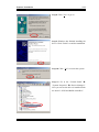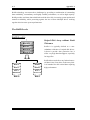
1
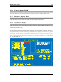
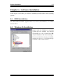
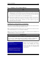
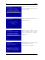
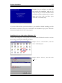
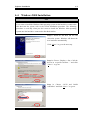
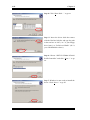
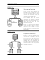
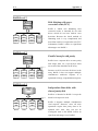
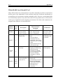
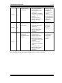
Copyright and Warranty Notice
The information in this document is subject to change without notice and does not
represent a commitment on part of the vendor, who assumes no liability or
responsibility for any errors that may appear in this manual.
No warranty or representation, either expressed or implied, is made with respect to
the quality, accuracy or fitness for any particular part of this document. In no event
shall the manufacturer be liable for direct, indirect, special, incidental or
consequential damages arising from any defect or error in this manual or product.
Product names appearing in this manual are for identification purpose only and
trademarks and product names or brand names appearing in this document are
property of their respective owners.
This document contains materials protected under International Copyright Laws. All
rights reserved. No part of this manual may be reproduced, transmitted or
transcribed without the expressed written permission of the manufacturer and
authors of this manual.
If you do not properly set the controller card settings causing the controller card to
malfunction or fail, we cannot guarantee any responsibility.
All brand names and trademarks shown in this manual are the property of their respective owners.
Hot Rod 100 Pro User’s Manual
Index
CHAPTER 1.
1-1.
1-2.
1-3.
1-4.
1-5.
THE INTRODUCTION OF HOT ROD 100 PRO
FEATURES ............................................................ 1-1
FEATURES OF THIS IDE RAID CONTROLLER CARD ............... 1-1
SPECIFICATIONS ...................................................................... 1-2
LAYOUT DIAGRAM .................................................................. 1-4
INTRODUCTION OF ULTRA ATA/100....................................... 1-5
REQUIREMENTS FOR ATTAINING ULTRA ATA/100 ................. 1-6
CHAPTER 2. HARDWARE INSTALLATION.......................... 2-1
2-1. INSTALLING THE HOT ROD 100 PRO ....................................... 2-1
2-2. CONNECTING HARD DRIVES.................................................... 2-2
CHAPTER 3. BIOS SETTING UTILITY ................................... 3-1
3-1. SET MOTHERBOARD CMOS SETUP......................................... 3-1
3-2. ENTER THE BIOS SETTING MENU ........................................... 3-1
3-3. CREATE RAID ........................................................................ 3-2
3-4. DELETE RAID......................................................................... 3-3
3-5. DUPLICATE MIRROR DISK ....................................................... 3-4
3-6. CREATE SPARE DISK ............................................................... 3-5
3-7. REMOVE SPARE DISK .............................................................. 3-5
3-8. SET DRIVE MODE .................................................................... 3-5
3-9. SELECT BOOT DISK ................................................................. 3-6
CHAPTER 4. SOFTWARE INSTALLATION ........................... 4-1
4-1. DOS INSTALLATION................................................................ 4-1
4-2. WINDOWS 9X INSTALLATION .................................................. 4-1
4-3. WINDOWS NT 4.0 INSTALLATION ........................................... 4-5
4-4. WINDOWS 2000 INSTALLATION .............................................. 4-9
APPENDIX A. THE INTRODUCTION OF RAID ........................A-1
APPENDIX B. BIOS FLASHING USER INSTRUCTIONS .........B-1
APPENDIX C. HOT ROD UTILITY INSTRUCTIONS.................C-1
MN-197-2A0-31
Rev. 1.00
APPENDIX D. TROUBLE SHOOTING (NEED ASSISTANCE?) ...D-1
APPENDIX E. HOW TO GET TECHNICAL SUPPORT ............. E-1
Hot Rod 100 Pro
Introduction of Hot Rod 100 Pro Features
1-1
Chapter 1. The Introduction of Hot Rod 100 Pro
Features
1-1. Features of This IDE RAID Controller Card
This IDE RAID controller card provides two IDE hard drive connectors that support the
latest Ultra ATA/100 (Also known as Ultra DMA/100) hard drives with the data transfer rate
of 100MB/sec. It is also backward compatible with Ultra ATA/66, Ultra ATA/33, Enhanced
IDE, and Fast ATA-2. Each IDE connector supports a master/slave combination of any IDE
device, including IDE, EIDE and Ultra-ATA standards.
The Hot Rod 100 Pro includes EZRAID for boosting disk performance and data protection.
The EZRAID function supports Striping (RAID 0), Mirroring (RAID 1), or
Striping/Mirroring (RAID 0+1) operation. For Striping operation, the identical drives can
read and write data in parallel to increase performance. The Mirroring operation increases
read performance through load balancing and elevator sorting while creating a complete
backup of your files. Striping with Mirroring operation offers both high read/write
performance and fault tolerance. The EZRAID function of the Hot Rod 100 Pro offers quick
and easy installation and configuration.
User’s Manual
1-2
Chapter 1
1-2. Specifications
1. Chipset
!
HPT370 Ultra DMA 100 IDE controller
2. BUS
!
PCI
3. Specification
!
Ultra DMA 100MB/sec data transfer rate
!
RAID 0 (stripping mode for boosting performance)
!
RAID 1 (mirroring mode for data security)
!
RAID 0 + 1 (stripping and mirroring)
!
Two independent ATA channels
!
256 Byte FIFO per ATA channels
!
Compliant with Plug & Play
!
Up to 4 IDE devices supported
4. Drive Modes Support
!
Ultra 5/4/3/2/1/0
!
PIO 4/3/2/1/0
!
DMA 2/1/0
5. BIOS Support
!
Friendly UI for RAID functions settings
!
Auto detects and supports Ultra Mode(ATA/EIDE) transfers
!
Recognizes drives up to 128 GB
6. Operating System Supports
!
Microsoft DOS 5.X and above
!
Microsoft Windows 95/98
!
Microsoft Windows 2000
!
Microsoft Windows NT4.0
!
ABIT Gentus 2.0 or later version (Linux)
Hot Rod 100 Pro
Introduction of Hot Rod 100 Pro Features
1-3
Table 1-1: Hot Rod 100 Pro specifications
Bus:
PCI
Drive Transfer Rate:
100MB/sec burst w/Ultra ATA/100 devices
Number of Supporting Drives: 4
Drive Modes:
Ultra DMA mode 5/4/3/2/1/0
DMA mode 2/1/0
PIO mode 4/3/2/1/0
Devices:
ATAPI Hard Drives
Operating Systems:
Microsoft DOS 5.X and above
Microsoft Windows 95/98
Microsoft Windows 2000
Microsoft Windows NT4.0
ABIT Gentus 2.0 (Linux)
BIOS:
1MB Flash ROM
Auto ID/Configure
Max. Storage: 128GB
Supports ACPI function
Hardware:
Bus mastering
Triple data channels (all DMA 33/66/100)
Utilities:
ABIT Vivid Installation
User’s Manual
1-4
Chapter 1
1-3. Layout Diagram
Figure 2-1: Hot Rod 100 Pro controller card component locations
Hot Rod 100 Pro
Introduction of Hot Rod 100 Pro Features
1-5
1-4. Introduction of Ultra ATA/100
Ultra ATA/100 enhances existing Ultra ATA/66 technology by increasing both performance
and data integrity. This new high-speed interface enhances the Ultra ATA/66 and Ultra/33
burst data transfer rate to 100 Mbytes/sec. The result is maximum disc performance using
the current PCI local bus environment. Figure 2-2 shows you the difference between the
Ultra ATA/33 and Ultra ATA/66 Cable.
Figure 2-2: The difference between Ultra ATA/33 and Ultra ATA/66 Conductor Cables
In order to achieve the Ultra ATA100 transfer speed you must have a system which supports
Ultra ATA/100 and equipped with, an Ultra ATA HDD, and Ultra ATA/66 cable. The correct
drivers must be loaded and an Ultra ATA/66 specific data cable must be used.
The Ultra ATA/66 cables use a Cable Select method rather than a Master / Slave scheme.
The drive must be jumped to enable Cable Select. The Boot drive (C:) is attached to the
connector on the end of the cable and the second drive is
attached to the middle connector. If an Ultra ATA/66
specific cable is not used, the drive will default to Ultra
ATA/33 mode.
Figure 2-3 shows you a photo of an Ultra ATA/66
Conductor Cable. An Ultra ATA/66 cable is a 40-pin, 80conductor cable with a black connector on one end, a blue
connector on the other end and a gray connector in the
middle. The additional 40 wires are ground lines that
reduce the crosstalk caused by the electro-magnetic fields
that build up during high-speed data transfers. In addition,
Figure 2-3: Photo of an
Ultra ATA/66 Cable
line 34 on the cable should be notched or cut (this may be
difficult to see).
User’s Manual
1-6
Chapter 1
Ultra ATA/100 is backwards compatible with all Ultra ATA/33/66 systems, but it will be
limited in its transfer mode to Ultra ATA/33/66 (Ultra DMA Mode 2 - 33 Mbytes/sec or
Ultra DMA Mode 2 - 66 Mbytes/sec) or PIO Mode 4 (16.6 Mbytes/sec). The Ultra ATA/100
hard drives are 100 percent backward compatible with both Ultra ATA/33/66, DMA and
with existing ATA (IDE) hard drives, CD-ROM drives, and host systems. The Ultra
ATA/100 protocol and commands are designed to be compatible with existing ATA (IDE)
devices and systems. Although a new 40-pin, 80-conductor cable is required for Ultra
ATA/100, the chip set pin connector remains the same at 40. Hard drives that support Ultra
ATA/100 also support Ultra ATA/33/66 and legacy ATA (IDE) specifications.
1-5. Requirements for Attaining Ultra ATA/100
There are four requirements for attaining Ultra ATA/100:
1. The drive must support Ultra ATA/100.
2. The motherboard and system BIOS (or an add-in controller) must support Ultra ATA/100.
3. The operating system must support Direct Memory Access (DMA); Microsoft Windows
2000, Windows NT, Windows 98, and Windows 95B (OSR2) support DMA.
4. The cable must be 80-conductor; the length should not exceed 18 inches.
If all the above requirements are met, you can enjoy the Ultra ATA/100 features of your
computer system.
Note
For obtaining the performance of Hot Rod 100 Pro, please use the Ultra ATA/66 cable
that comes with the package.
Hot Rod 100 Pro
Hardware Installation
2-1
Chapter 2. Hardware Installation
This IDE RAID controller card is as easy to install as any other computer peripheral. It uses
the Plug & Play design concept. First, plug this controller card into any PCI slot on your
motherboard. Second, connect the Ultra ATA/100 devices to its IDE connectors using the
included Ultra ATA/66 cables.
2-1. Installing the Hot Rod 100 Pro
Installing this controller card into your computer is a simple process. You just have to insert
the card into any available PCI slot on the motherboard (see figure below).
➠ Open your computer case.
➠ Remove the inside slot cover of an available PCI slot on the motherboard.
➠ Insert this controller card into the open slot.
➠ Fasten the controller card bracket to the case.
➠ Attach the two-threaded IDE HDD LED connector of the computer case to HDD-LED
connector on this controller card. (Note: Watch out the pin orientation.)
➠ Connect the Ultra ATA/100 HDD to the IDE connectors on this controller card.
Figure 2-1: The installation of the Hot Rod 100 Pro controller card
User’s Manual
2-2
Chapter 2
2-2. Connecting Hard Drives
This IDE RAID controller card provides two IDE hard drive connectors that support Ultra
ATA/100 (Also known as Ultra DMA/100) specification.
How to install the Ultra ATA/66 Cable Assembly:
" Connect the BLUE connector of the first
Ultra ATA/66 cable to the IDE1 connector
on this IDE RAID controller card. (Note that
the colored cable edge indicates Pin # 1.)
" Connect the BLACK connector of this
Ultra ATA/66 cable to the Master Drive.
" Connect the GRAY connector of this
Figure 2-2. How to connect an ATA/66
Cable to this IDE RAID controller
Ultra ATA/66 cable to the Slave Drive (if
you are using more than two hard drives).
" For the second Ultra ATA/66 cable
connection, please follow the previous procedure.
" Each connector on the Ultra ATA/66 cable assembly has a small polarization tab centrally
located on the body of the plastic. This fits into the matching slot on the mating plugs on
this IDE RAID controller card and the drives, thus assuring positive mating (pin #1 to pin
#1). Please refer to figure 2-2.
" When two hard drives are attached,
configure each drive as a Master
Table 2-1: Hot Rod 100 Pro Hard Drive Setup
Total Drives IDE 1
IDE 2
(with no Slave attached) and each
1
Master
---
hard drive on a separate channel.
2
Master
Master
Check the hard drive setup for
3
Master and Slave Master
4
Master and Slave Master and Slave
details on Master and Slave
settings as shown in table 2-1. For
better performance, use all available connectors before chaining a slave drive.
" For optimal performance, install all identical drives of the same model and capacity. The
drives’ matched performance allows the array to the function better as a single drive.
" For maximum IDE fault tolerance, each mirrored pair should be installed on separate IDE
connectors.
Hot Rod 100 Pro
Hardware Installation
2-3
Connecting hard drives with onboard ATAPI CD-ROM:
Please DO NOT attach ATAPI devices to
this IDE RAID controller card. Hot Rod 100
Pro is for hard drives only.
ATAPI CD-ROM
ATAPI IDE CD-ROM drives or other
devices can be installed on motherboard or
add-on IDE controllers. No configuration is
necessary on the motherboard BIOS setup.
Bootable
Secondary
Connecting hard drives with onboard IDE controller:
This IDE RAID controller card can coexist
with onboard or add-on IDE controller(s)
and hard drives installed.
If the motherboard’s CMOS has a “boot to
SCSI” option, it is possible to boot from this
IDE
RAID
controller
card
and
still
recognize the onboard non-bootable drives.
If the motherboard’s CMOS does not allow
booting to SCSI, the boot drive must be
Secondary
Bootable
attached on the onboard IDE controller.
User’s Manual
2-4
Chapter 2
Connecting hard drives with SCSI controller:
This IDE RAID controller card is bootable
with a SCSI controller in the system. The
adapter with the lower BIOS address will be
bootable. If it is necessary to change the
boot sequence, swap the Hot Rod 100 Pro
slot position with that of SCSI card’s PCI
slot.
Secondary
Hot Rod 100 Pro
Bootable
BIOS Setting Utility
3-1
Chapter 3. BIOS Setting Utility
In this chapter we will discuss the BIOS setting procedure of this IDE RAID controller card
before starting the software installation.
3-1. Set Motherboard CMOS Setup
No changes are necessary in the motherboard CMOS setup for resources or drive types. As
this IDE RAID controller card is a PCI Plug and Play device, the motherboard’s PCI PnP
BIOS automatically assigns the Interrupt and Port address. For this IDE RAID controller
card to be the bootable IDE controller, confirm in the motherboard’s Standard CMOS Setup
that the drive types (for hard disk drives) are set for “Not Installed” or “None”. Or use the
“Boot to SCSI” option, if this setting is available in the motherboard’s BIOS. No changes
are needed for CD-ROM drives that are attached to the motherboard IDE controller.
3-2. Enter the BIOS Setting Menu
After you have installed this IDE RAID controller card and attached the hard disks, reboot
your system. Press <CTRL> and <H> key while booting up the system to enter the BIOS
setting menu. The main menu of BIOS Setting Utility appears as shown below:
User’s Manual
3-2
Chapter 3
For selecting the options in the menu, you may:
# Press F1 to view array status.
# Press ↑↓ (up, down arrow) to choose the option you want to confirm or to modify.
# Press Enter to confirm the selection.
# Press Esc to return to the top menu.
3-3. Create RAID
This item allows you to create a RAID array with the hard disks attached to this IDE RAID
controller card.
After you have selected the function you want in the main menu, press the <Enter> key to
enter the sub menu as shown below:
Warning
All the data stored in the hard disks will be lost after created RAID!
Hot Rod 100 Pro
BIOS Setting Utility
3-3
Array Mode:
This item allows you to select the appropriate RAID mode for the desired array. There are
four modes to choose.
✏ Striping (RAID 0):
This item is recommended for high performance usage. Requires at least 2 disks.
✏ Mirror (RAID 1):
This item is recommended for data security usage. Requires at least 2 disks.
✏ Striping and Mirror (RAID 0+1):
This item is recommended for data security and high performance usage. Allows
Mirroring with a Strip Array. Requires 4 disks only.
✏ Span (JBOD):
This item is recommended for high capacity without redundancy or performance
features usage. Requires at least 2 disks.
Select Disk Drives:
This item allows you to select the disk drives to be used with the RAID array.
Block Size:
This item allows you to select the block size of the RAID array. There are five options: 4K,
8K, 16K, 32K, and 64K.
Start Creation Process:
After you have made your selection, choose this item and press <Enter> to start creation.
3-4. Delete RAID
This item allows you to remove a RAID Array on this IDE RAID controller card.
Note: After you have made and confirmed this selection, all the data stored in the hard disk
will be lost. (The entire partition configuration will be deleted too.)
User’s Manual
3-4
Chapter 3
3-5. Duplicate Mirror Disk
This item allows you to select the disk you wish to duplicate in preparation for a “Mirror
Disk Array”.
After you had selected the function you want in the main menu, press the <Enter> key to
enter the sub menu as shown below:
✏ Select Source Disk:
This item is to select the source disk. The size of the source disk must be smaller
or equal to the one of the target disk.
✏ Select Target Disk:
This item is to select the target disk. The size of target disk must be greater or equal
to the one of the source disk.
✏ Start Duplicating Process:
After you had selected this item, the BIOS setting will take up to 30 minutes to run
the duplication. Please wait or you may press <Esc> to cancel.
Hot Rod 100 Pro
BIOS Setting Utility
3-5
3-6. Create Spare Disk
This item allows you to select the disk to be used as a spare for a Mirror Disk Array.
3-7. Remove Spare Disk
This item allows you to remove the spare disk from a Mirror Disk Array.
3-8. Set Drive Mode
This item allows you to select the drive transfer mode for the hard disk(s) attached to this
IDE RAID controller card.
Use the up/down arrow to select the menu option to “Set Drive Mode” and press <Enter>. In
the Channel Status, select the channel you would like to set and press the <Enter> key. There
will be an asterisk mark in the parentheses indicating that the channel selection has been
done. Choose the mode from the pop-up menu. You can choose from PIO 0 ~ 4, MW DMA
0 ~ 2, and UDMA 0 ~ 5.
User’s Manual
3-6
Chapter 3
3-9. Select Boot Disk
This item allows you to select the boot disk among the hard disk(s) attached to this IDE
RAID controller card.
Use the up/down arrow to select the menu option to “Select Boot Disk” and press <Enter>.
In the Channel Status, select the channel you would like to set as the bootable disk and press
the <Enter> key. There will be an asterisk mark in the parentheses indicating that the
channel selection has been done. Note: Your PC or server must be configured to use the
Hot Rod 100 Pro as the bootable controller. The system will then use the bootable
array as the (fixed) boot C: drive.
Hot Rod 100 Pro
Software Installation
4-1
Chapter 4. Software Installation
In this chapter we will show you the driver installation procedure under various operating
systems.
4-1. DOS Installation
This IDE RAID card BIOS supports DOS 5.x (or above) and Windows 3.1x without
software driver.
4-2. Windows 9x Installation
Step 1: After the Windows 9x operating
system had been installed and rebooted
successfully, go to the “Control Panel” $
“System Properties” $ “Device Manager”.
You can see the driver is not yet installed,
and there is a device of “? PCI Mass Storage
Controller” under “Other devices”.
User’s Manual
4-2
Chapter 4
Step 2: Click the right button of your mouse
on the “? PCI Mass Storage Controller”, and
then go to “Driver” tab. Click “Update
Driver” to go to the next step.
Step 3: The wizard is going to install the
PCI Mass Storage Controller. Click “Next
>” to go to the next step.
Step 4: Choose “Display a list of all the
drivers in a specific location…” and click
“Next >” to go on.
Hot Rod 100 Pro
Software Installation
4-3
Step 5: Choose “SCSI controllers” and click
“Next >” to go on.
Step 6: Click “Have Disk…” to go on.
Step 7: Insert the driver disk that comes
with the Hot Rod 100 Pro and type the path
in the text box “a:\WIN” (“a:\” is your
floppy drive letter), or “E:\Drivers\Win9x”
(E:\ is your CD-ROM drive letter).
Click “OK” to go on.
Step 8: Choose “HPT370 UDMA/ATA100
RAID Controller” and click “Next >” to go
on.
User’s Manual
4-4
Chapter 4
Step 9: Windows is now ready to install the
driver. Click “Next >” to go on.
Step 10: Windows has finished installing
the driver. Click “Finish” to end the
installation.
Step 11: After rebooting the system, go to
the “Control Panel” $ “System Properties”
$ “Device Manager”. Now you can see the
driver is installed under the item of “SCSI
controllers”.
Hot Rod 100 Pro
Software Installation
4-5
4-3. Windows NT 4.0 Installation
Note
#
Before you start to install Windows NT 4.0, you have to create a driver disk for the
Hot Rod 100 Pro. You can copy the Ultra ATA/100 (Hot Rod 100) driver files from
the CD-Title that comes with this controller card. The path for the Ultra DMA/100
driver files is “E:\drivers\winnt (E is your CD-ROM drive letter).”
#
Please note two things before you copy the driver files to diskette. First, the driver
files must be copied to the root directory of the diskette. Second, you have to set
your system to “Show all files”. Otherwise you will be unable to copy some
important system files to diskette.
Installing drivers during Windows NT installation:
If the NT 4.0 is first installed on the ATA100 drive connected to the Hot Rod 100 Pro
controller card, follow the following installation procedure:
Step 1: Install this IDE RAID controller card in any available PCI slot and then connect
your ATA100 hard disk to it (refer to hardware installation).
Step 2: Set your system to boot from “Drive A” and then insert the Windows NT
installation diskette 1/3. Power on your computer.
Installation Note
If you are installing NT 4.0 from a CD-ROM, please press the “F6” key immediately
when the message “Setup is inspecting your computer’s hardware configuration…”
appears. Then press “S” to configure an additional adapter (Hot Rod 100 Pro).
Step 1: The setup program will display a
message about installing mass storage
devices (see figure left) while you install
NT4.0. Please press “S” to install Hot Rod
100 Pro driver.
User’s Manual
4-6
Chapter 4
Step 2: Select “Other, requires disk
provided by a hardware manufacturer”, and
then press <ENTER>.
Step 3: Insert the driver disk into drive A
and press <ENTER>.
Step 4: Use the UP or DOWN arrow key to
move the highlight to the mass storage
device you want and press <ENTER> to
continue setup.
Step 5: Windows NT setup has recognized
this IDE RAID controller card.
Press <ENTER> to continue setup.
Hot Rod 100 Pro
Software Installation
4-7
Step 6: After you configure your hard disk
and specify the installation path, the NT
setup will ask you to insert this IDE RAID
controller card driver disk into drive A again.
Insert the driver disk, and then press
<ENTER> to continue setup.
If you have followed the steps described above, you should be finished installing your Hot
Rod 100 Pro controller. For the rest of the Windows NT installation steps, please follow the
instructions displayed in the NT setup program.
Installing drivers with existing Windows NT:
If there is an existing NT 4.0 file system, you can install this IDE RAID controller card into
the existing system by the following procedure:
Step 1: Go to “Control Panel”, and then
enter “SCSI Adapters”.
Step 2: Select “Drivers”, and then click
“Add…”.
User’s Manual
4-8
Chapter 4
Step 3: Click “Have Disk…” to go on.
Step 4: Insert this IDE RAID controller card
driver disk into drive A, and then click
“OK.”
Step 5: Click “OK” to go on.
Step 6: Enter “A:\” in the blank space, and
then click “Continue”.
Step 7: Click “Yes” to restart your
computer.
Hot Rod 100 Pro
Software Installation
4-9
4-4. Windows 2000 Installation
Note
If you want to install the Windows 2000 operating system on the hard drive connected to
Hot Rod 100 Pro, please refer to the NT4.0 installation procedure. The following
procedure is used only when you don’t want to install the Windows 2000 operating
system onto the hard drive connected to Hot Rod 100 Pro.
Step 1: Install the Hot Rod 100 Pro and
reboot the system. Windows will detect the
new hardware automatically.
Click “Next>” to go to the next step.
Step 2: Choose “Display a list of all the
drivers in a specific location…” and click
“Next >” to go on.
Step
3:
Choose
“SCSI
and
RAID
controllers” and click “Next >” to go on.
User’s Manual
4-10
Chapter 4
Step 4: Click “Have Disk…” to go on.
Step 5: Insert the driver disk that comes
with the Hot Rod 100 Pro and type the path
in the text box “A:\2K” (“A:\” is your floppy
drive letter), or “D:\Drivers\Win2k” (D:\ is
your CD-ROM drive letter).
Step 6: Choose “HPT370 UDMA/ATA100
RAID Controller” and click “Next >” to go
on.
Step 7: Windows is now ready to install the
driver. Click “Next >” to go on.
Hot Rod 100 Pro
Software Installation
4-11
Step 8: Click “Yes” to go on.
Step 9: Windows has finished installing the
driver. Click “Finish” to end the installation.
Step 10: Click “Yes” to restart the system.
Step 11: Go to the “Control Panel” $
“System Properties” $ “Device Manager”.
Now you can see the driver is installed under
the item of “SCSI and RAID controllers”.
User’s Manual
4-12
Hot Rod 100 Pro
Chapter 4
The Introduction of RAID
A-1
Appendix A. The Introduction of RAID
What is RAID?
RAID (Redundant Array of Inexpensive/Independent Disks) technology was developed to
offer a combination of outstanding data availability, excellent performance, and high
capacity that one single disk drive can not match. A RAID array is defined as two or more
disks grouped together to appear as one single device to the host system, which can tolerate
the failure of a drive without losing data, and which can operate independently from each
other.
To manage MTBF (Mean Time Between Failures) and prevent any single drive failure
causing data loss within an array, UC Berkeley scientists proposed five types of redundant
array architectures, defining them as RAID levels 1 through 5. Each RAID level has its own
strengths and weaknesses, and is well suited for certain types of applications and computing
environments. RAID 1, RAID 3 and RAID 5 of these five types are commonly used. RAID
2 and RAID 4 do not offer any significant advantages over these other types. RAID 3 is
designed for single-user or data-intensive environments, such as imaging or data acquisition
that access extremely large sequential records. This leaves RAID 1 and RAID 5 as the RAID
levels applicable for networked and transaction processing-based environments utilizing
NetWare, Windows NT, Unix, and OS/2.
In addition to these five redundant array architectures, it has become popular to refer to a
non-redundant array of disk drives as RAID 0 array.
Why RAID?
Data security is a very important issue for system administrators. They have to adopt
efficient methods of data protection to guard against potential losses due to drive failures.
Tape-based backups are used to be one solution for data security, but this method is
becoming a task more difficult. The demand to store increasingly large software
applications will impel disk capacities to exceed 10GBs by the end of 1997. Slow,
cumbersome tape backup solutions lose their effectiveness for servers and workstations.
RAID technology is another solution for data security. There are a number of factors
responsible for the growing adoption of arrays for critical network storage. Because today’s
applications create larger files, the need for network storage has increased proportionately.
To accommodate expanding storage requirements, users are adding disk drives --- raising
the probability of drive failures. In addition, the development of CPU speed has exceeded
data transfer rates to storage media, causing I/O bottlenecks for networking applications.
User’s Manual
A-2
Appendix A
RAID technology overcomes these challenges by providing a combination of outstanding
data availability, extraordinary and highly scalable performance, as well as high capacity.
RAID provides real-time data rebuild when a disk drive fails, increasing system uptime and
network availability, while protecting against the loss of data. Multiple drives working
together also increases system performance.
The RAID Levels
RAID Level 0:
..
.
Striped Disk Array without Fault
Tolerance
Block D
Block C
Block B
Block A
RAID 0 is typically defined as a nonredundant collection of striped disk drives.
It doesn’t provide data protection but it
offers very high data throughput, especially
for large files.
RAID 0 does not deliver any fault tolerance.
All data is lost if any drive in the array fails.
Block A
Block B
It is intended for non-critical data requiring
Block C
Block D
high performance.
Block E
Block F
Block G
etc …
Disk 0
Disk 1
Hot Rod 100 Pro
The Introduction of RAID
A-3
RAID Level 1
Mirroring and Duplexing
Block D
Block C
Block B
Block A
RAID 1 provides 100% redundancy by
mirroring one drive to another one. In the
event of a disk drive failure, the array
controller will automatically switch the
read/write activity to another drive.
Each
individual
drive
can
execute
simultaneous read operations. Mirroring
Block A
Block A
Block B
$ Mirror
Block B
Block C
Block C
Block D
Block D
Disk 0
Disk 1
thus doubles the read performance of a
single
drive
and
leaves
the
write
performance unchanged.
RAID 1 is a good entry-level redundant
system, since only two drives are required.
However, the cost of RAID 1 is higher
because one drive has to be used to store
duplicate data.
RAID Level 0+1
..
.
Performance and Security
Block D
Block C
Block B
Block A
RAID 0+1, which uses Hamming error
correction codes, is intended for use with
drives which do not have built-in error
detection. Because the check method of
Hamming code is very complicated, and
more than one drive is required to store ECC
Block A
Disk 0 Block C
Block E
Block G
Stripe
Block B
Disk 1 Block D
Block F
Block H
Block A
Block C
Disk 2
Block E
Block G
information, RAID 2 offers no significant
advantages over RAID 3.
Stripe
Block B
Block D Disk 3
Block F
Block H
User’s Manual
A-4
Appendix A
RAID Level 2
Disk Striping with errorcorrection code (ECC)
Block D
Block C
Block B
Block A
RAID 2, which uses Hamming error
correction codes, is intended for use with
drives which do not have built-in error
A0
A1
detection. Because the check method of
A2
B0
B1
B2
Hamming
C0
C1
C2
Code
D0
D1
D2
Disk 0
Disk1
Disk 2
….
Hamming code is very complicated, and
more than one drive is required to store ECC
Disk3
information, RAID 2 offers no significant
advantages over RAID 3.
RAID Level 3
Parallel transfer with parity
Block D
Block C
Block B
Block A
Stripe 0
RAID 3 uses a separate drive to store parity
and stripes data on a byte-by-byte basis
Stripe 1
Stripe 2
Stripe 0, 1, 2
Parity
A0
A1
A2
A Parity
B0
B1
B2
B Parity
C0
C1
C2
C Parity
D0
D1
D2
D Parity
Disk 0
Disk1
Disk 2
Disk3
across all of the data disks in the array.
Because each I/O accesses all drives in the
array, RAID 3 does not support multiple,
simultaneous read/write requests. It is
optimized for large, sequential data requests.
RAID Level 4
Independent Data disks with
shared parity disk
DATA
ABCD
RAID 4 is identical to RAID 3 except the
Block 0
Block 1
Block 2
Block 0, 1, 2
Parity
block level stripes are used.
A0
A1
A2
A Parity
RAID 4 supports multiple simultaneous
B0
B1
B2
B Parity
C0
C1
C2
C Parity
read requests. However, since all write
D0
D1
D2
D Parity
operations require that parity data to be
Disk 0
Disk1
Disk 2
Disk3
updated each time, they can not be
overlapped. And so the RAID 4 offers no
significant advantages over RAID5.
Hot Rod 100 Pro
The Introduction of RAID
A-5
RAID Level 5
Independent Data disks with
distributed parity blocks
DATA
ABCD
RAID 5 also stripes data at a block level
across several drives. But it distributes
A Block
B Block
C Block
D Block
parity among the drives, which avoids the
B0
C0
0 Parity
A1
B1
1 Parity
D1
A2
2 Parity
C2
D2
dedicated parity drive. Each drive takes
3 Parity
B3
C3
D3
turns storing parity information for a
Disk 0
Disk1
Disk 2
Disk3
different series of stripes. RAID 5 can
A0
write bottleneck caused by the single
execute read/write to disk drives either in
parallel or independently.
User’s Manual
A-6
Appendix A
Which RAID Level Should I Use?
Many different disk array configurations are possible, depending on end-user requirements
and the goals of the manufacture. Each controller design has a different functionality to
accomplish specific performance and data availability goals. Therefore, no individual RAID
level is inherently superior to any other. Each of the five array architectures is well suited for
certain types of applications and computing environments. The follow table summarizes the
strengths and weaknesses of each RAID level.
RAID
Level
Min.
No. of
Drive
s
RAID 0
2
Characteristics /
Strengths
Description
!
!
Striped Disk
Array without
Fault Tolerance
Mirroring and
Duplexing
!
!
!
!
!
RAID 1
2
!
!
Performance and
Security
!
!
RAID
0+1
4
!
RAID 2
Not
used
in
LAN
Hot Rod 100 Pro
Disk Striping with
error-correction
code (ECC)
!
Highest I/O Performance
Very simple design
Easy to implement
100% redundancy of
data
Twice the Read
transaction rate of a
single disk, same Write
transaction rate as single
a disk
Simplest RAID storage
subsystem design
The combination of
Striping and Mirroring
Offers the speed
advantages of RAID
level 0 combined with
the data reliability
advantages of RAID
level 1
Previously used for
RAM error
environments correction
(known as Hamming
Code) and in disk drives
before the use of
embedded error
correction
Weaknesses
!
!
No redundancy
One drive fails,
all data is lost
High
redundancy cost
overhead
!
Need twice the
data capacity
!
No practical use
The Introduction of RAID
!
Parallel transfer
with parity
A-7
!
!
!
RAID 3
3
!
!
RAID 4
Independent Data
disks with shared
parity disk
3
!
!
!
!
Independent Data
disks with
distributed parity
blocks
!
!
!
RAID 5
3
!
!
Very high Read data
transfer rate
Very high Write data
transfer rate
Excellent performance
for large, sequential data
requests
Low ratio of ECC
(Parity) disks to data
disks means high
efficiency
Very high Read data
transaction rate
High aggregate Read
transfer rate
Low ratio of ECC
(Parity) disks to data
disks means high
efficiency
Highest Read data
transaction rate
Medium Write data
transaction rate
Best cost/performance
for transaction-oriented
networks
Supports multiple,
simultaneous Read and
Write
Low ratio of ECC
(Parity) disks to data
disks means high
efficiency
!
!
!
Doesn’t support
multiple,
simultaneous
Read and Write
requests
Transaction rate
equal to that of a
single disk drive
at best (if
spindles are
synchronized)
Worst Write
transaction rate
and Write
aggregate
transfer rate
!
!
Write
performance is
slower than
RAID 0 or
RAID1
Note: Hot Rod 100 Pro only supports RAID level 0, 1, and 0+1 currently.
User’s Manual
A-8
Hot Rod 100 Pro
Appendix A
BIOS Flashing User Instructions
B-1
Appendix B. BIOS Flashing User Instructions
This IDE RAID controller card is equipped with 1 Mbit flash BIOS onboard. If you receive
information about an update for this IDE RAID controller card BIOS from our website
(http://www.abit.com.tw) or technical support, download the BIOS file and save it under the
name “BIOS”, then follow the procedure below to upgrade this IDE RAID controller card
BIOS:
Step 1: Copy the files “load.exe (included in this IDE RAID Driver Disk)” and “BIOS” to a
new floppy.
Step 2: Reboot your system and go into the pure DOS environment.
Step 3: Insert the floppy that contains the files “load.exe” and “BIOS” into drive A.
Step 4: At the “A:\>” prompt, type “load BIOS” and then press “enter”.
Step 5: Remove the floppy A, and then restart your system.
User’s Manual
B-2
Hot Rod 100 Pro
Appendix B
Hot Rod Utility Instructions
C-1
Appendix C. Hot Rod Utility Instructions
In order to provide you with the on-screen monitoring function about the device information
of disk array, you may install the “Hot Rod Utility” onto your system. Please insert the Hot
Rod 100 Pro CD-Title into your CD-ROM drive. It should execute the program
automatically. If not, you can go to the CD location and execute the execution file from the
main directory of the CD-Title. After it is executed, you will see the screen shot below.
Move the cursor to “Utility” and click on it
to go to the next step.
Move the cursor to “RAID Status Monitor
Utility” and click on it to go to the next step.
Click “Next>” to go on.
User’s Manual
C-2
Appendix C
Type in the information of your name and
company and then click “Next>” to go on.
Now you can choose the folder for the
destination location you want. We suggest
you use the default folder as the destination
location. When you are sure of the folder,
click “Next>” to go on.
Now you can select the program folder. The
setup wizard will add program icons to those
program folders listed. Click “Next>” to go
on.
The system will start copying files. Click
“Next>” to go on.
Hot Rod 100 Pro
Hot Rod Utility Instructions
C-3
When the installation is completed, choose
“Yes, I want to restart my computer now.” In
the check box and click “Finish” to end the
setup.
After the system restart, you can run this “Stripe & Mirror Settings” monitoring program.
Move the cursor to where the execution file
is, shown left.
The monitoring screen pops up. Note that
there will be a shortcut icon appears in the
tool bar. This is used for bringing out the
screen again after you had clicked the
“Minimize” icon on the upper right corner
of the screen. This short cut icon will
disappear after you click the “Exit” icon.
Now you are in the monitoring screen. Your current device allocation is viewable at a glance.
Move the cursor to the drive icon you want to view and click on it.
User’s Manual
C-4
Hot Rod 100 Pro
Appendix C
Trouble Shooting (Need Assistance?)
D-1
Appendix D. Trouble Shooting (Need Assistance?)
Q&A
Q: May I use hard drives with different capacity or transfer mode?
A: In order to get optimized performance, we suggest using hard drives with the same
model.
Q: How to assign a booting device?
A: You may press <Ctrl><H> to assign a booting device in RAID BIOS (user’s manual
section 3-9).
Q: Why can’t I see correct capacity in FDISK utility?
A: It's a well-known issue of win95/98's FDISK utility. If an IBM 75GB hard disk DTLA
307075 only gets 7768MB in Win95/98’s FDISK utility, please contact Microsoft for a
latest version of FDISK utility or download IBM's Disk Manager DiskGo! 2.5 to fix it.
For
windows
2000,
there
is
no
such
a
64GB
issue.
http://www.storage.ibm.com/techsup/hddtech/welcome.htm
Q: How to create a striping and mirror array (RAID 0+1)?
A: You need four drives (Appendix A), every two of them on the same channel/cable build
a striping array. Then create a mirror array by these two striping arrays (Appendix A-3).
(i) Press <Ctrl> <H> to setup configuration
(ii) Choose item 1 to Create RAID.
(iii) Choose item 1 to set Array Mode as Striping and Mirror (RAID 0+1).
(iv) Choose item 2 to Select Disk Drives. There are two striping arrays built
automatically and you only have to enter twice.
(v) Choose item 4 to Start Creation Process.
(vi) Press <Esc> to finish setting and leave RAID BIOS.
Q: How to rebuild a mirror array when one of the drives corrupts?
A: You need to delete previous array setting, duplicate the data, then rebuild a new array
setting (user’s manual 3-5).
User’s Manual
D-2
Appendix D
(i) Press <Ctrl><H> to setup configuration
(ii) Choose item 2 to Delete Array.
(iii) Choose item 3 to Duplicate Mirror Disk.
(iv) Choose sub item 1 to Select Source Disk, the one with data on it.
(v) Choose sub item 2 to Select Target Disk, the brand new and empty one.
(vi) Choose sub item 3 to Start Duplication Process.
(vii) After duplication process completes, press <Esc> to leave RAID BIOS.
Q: Why I see “NO ROM BASIC SYSTEM HALTED” when booting?
A: There isn’t any activated primary partition in you system. Please use FDISK or any
other utilities to create/set one.
Hot Rod 100 Pro
Trouble Shooting (Need Assistance?)
D-3
Do & Don’t
1.
Do always use the same model drives to achieve best quality and performance.
Different firmware has different timing characteristic, thus may somewhat decrease
the RAID performance.
2.
If you have two drives, do connect them on two different channels as master drive
please.
3.
When attach drives to the RAID card, do make sure the master/slave jumper
settings are correct please. If there is only one drive on one channel/cable, do set it
as master or single drive.
4.
Do always use 80 conductor cables please.
5.
Don’t connect any ATAPI devices (CD-ROM, LS-120, MO, ZIP, removable HD
etc.) on the RAID card please.
6.
For the best performance result, please do use the Ultra ATA 66/100 Hard Disks.
User’s Manual
D-4
Appendix D
% Technical Support Form
! Company Name:
☎ Phone Number:
" Contact Person:
# Fax Number:
& E-mail Address:
IDE Card Product
Name
Motherboard
Manufacturer,
Model Name and
Chipset type
Operating System
Type
Hardware name
CPU Type and
Speed
HDD
IDE1
IDE2
CDIDE1
IDE2
ROM
Drive
System Memory
Size (SDRAM)
Add-On Card
'
Problem Description:
Hot Rod 100 Pro
*
IDE Card BIOS
Version
IDE Card Software
and Driver Version
*
*
*
*
*
*
Type
*
*
Specifications
How to Get Technical Support
E-1
Appendix E. How to Get Technical Support
(From our website) http://www.abit.com.tw
(In North America) http://www.abit-usa.com
(In Europe) http://www.abit.nl
Thank you for choosing ABIT products. ABIT sells all our products through distributors,
resellers and system integrators, we have no direct sales to end-users. Before sending email
for tech support please check with your resellers or integrators if you need any services, they
are the ones who sold you your system and they should know best as to what can be done,
how they serve you is a good reference for future purchases.
We appreciate every customer and would like to provide the best service to you. Providing
fast service to our customers is our top priority. However we receive many phone calls and a
huge amount of email from all over the world. At the present time it is impossible for us to
respond to every single inquiry. Therefore it is quite possible that if you send an email to us
that you may not receive a response.
We have done many compatibility tests and reliability tests to make sure our products have
the best quality and compatibility. In case you need service or technical support, please
understand the constraint we have and always check with the reseller who sold the
product to you first.
To expedite service, we recommend that you follow the procedures outlined below before
contacting us. With your help, we can meet our commitment to provide the best service to
the greatest number of ABIT customers:
1. Check the Manual. It sounds simple but we have taken a lot of care in making a well
written and thorough manual. It is full of information that doesn't only pertain to
motherboards. The CD-ROM included with your board will have the manual as well as
drivers. If you don't have either one go to our Program Download Area of the website or
FTP server at: http://www.abit.com.tw/download/index.htm
2. Download latest BIOS, software or drivers. Please go to our Program Download area
on our website to check to see if you have the latest BIOS. They are developed over
periods of time to fixes bugs or incompatibilities. Also please make sure you have the
latest drivers from your peripheral cards makers!
3. Check the ABIT Technical Terms Guide and FAQ on our website. We are trying to
expand and make the FAQs more helpful and information rich. Let us know if you have
any suggestions. For hot topics check out our HOT FAQ!
User’s Manual
E-2
Appendix E
4. Internet Newsgroups. They are a great source of information and many people there
can offer help. ABIT's Internet News group, alt.comp.periphs.mainboard.abit, is an
ideal forum for the public to exchange information and discuss experiences they have
had with ABIT products. Many times you will see that your question has already been
asked before. This is a public Internet news group and it is reserved for free discussions,
Here is a list of some of the more popular ones:
alt.comp.periphs.mainboard.abit
alt.comp.periphs.mainboard
comp.sys.ibm.pc.hardware.chips
alt.comp.hardware.overclocking
alt.comp.hardware.homebuilt
alt.comp.hardware.pc-homebuilt
5. Ask your reseller. Your ABIT authorized distributor should be able to provide the
fastest solution to your technical problem. We sell our products through distributors who
sell to resellers and stores. Your reseller should be very familiar with your system
configuration and should be able to solve your problem much more efficiently than we
could. After all, your reseller regards you as an important customer who may purchase
more products and who can urge your friends to buy from him or her as well. They
integrated and sold the system to you. They should know best what your system
configuration is and your problem. They should have reasonable return or refund
policies. How they serve you is also a good reference for your next purchase.
6. Contacting ABIT. If you feel that you need to contact ABIT directly you can send email
to the ABIT technical support department. First, please contact the support team for the
branch office closest to you. They will be more familiar with local conditions and
problems and will have better insight as to which resellers offer what products and
services. Due to the huge number of emails coming in every day and other reasons, such
as the time required for problem reproduction, we will not be able to reply to every email.
Please understand that we are selling through distribution channels and don't have the
resources to serve every end-user. However, we will try to do our best to help every
customer. Please also remember that for many of our technical support team English is a
second language, you will have a better chance of getting a helpful answer if your
question can be understood in the first place. Be sure to use very, simple, concise
language that clearly states the problem, avoid rambling or flowery language and always
list your system components. Here is the contact information for our branch offices:
Hot Rod 100 Pro
How to Get Technical Support
E-3
In North America and South America please contact:
ABIT Computer (USA) Corporation
46808 Lakeview Blvd.
Fremont, California 94538 U.S.A.
[email protected]
[email protected]
Tel: 1-510-623-0500
Fax: 1-510-623-1092
In the UK and Ireland:
ABIT Computer Corporation Ltd.
Caxton Place, Caxton Way,
Stevenage, Herts SG1 2UG, UK
[email protected]
[email protected]
Tel: 44-1438-741 999
Fax: 44-1438-742 899
In Germany and Benelux (Belgium, Netherlands, Luxembourg)
countries:
AMOR Computer B.V. (ABIT's European Office)
Van Coehoornstraat 5a,
5916 PH Venlo, The Netherlands
[email protected]
[email protected]
Tel: 31-77-3204428
Fax: 31-77-3204420
All other territories not covered above please contact:
Taiwan Head Office
When contacting our headquarters please note we are located in
Taiwan and we are 8+ GMT time. In addition, we have holidays that
may be different from those in your country.
ABIT Computer Corporation
3F-7, No. 79, Sec. 1, Hsin Tai Wu Rd.
Hsi Chi, Taipei Hsien
Taiwan, R.O.C.
User’s Manual
E-4
Appendix E
[email protected]
[email protected]
[email protected]
Tel: 886-2-2698-1888
Fax: 886-2-2698-1811
7. RMA Service. If your system has been working but it just stopped, but you have not
installed any new software or hardware recently, it is likely that you have a defective
component. Please contact the reseller from whom you bought the product. You should
be able to get RMA service there.
8. Reporting Compatibility Problems to ABIT. Because of tremendous number of email
messages we receive every day, we are forced to give greater weight to certain types of
messages than to others. For this reason, any compatibility problem that is reported to us,
giving detailed system configuration information and error symptoms, will receive the
highest priority. For the other questions, we regret that we may not be able to reply
directly. But your questions may be posted to the internet news group in order that a
larger number of users can have the benefit of the information. Please check the news
group from time to time.
Thank you, ABIT Computer Corporation
http://www.abit.com.tw
Hot Rod 100 Pro