1
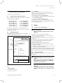
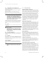
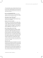
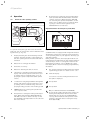
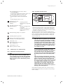
For the owner
Operating manual
ecoCRAFT
Gas condensing boiler
GB
VKK GB 806/3-E-H
VKK GB 1206/3-E-H
VKK GB 1606/3-E-H
VKK GB 2006/3-E-H
VKK GB 2406/3-E-H
VKK GB 2806/3-E-H
Contents
Appliance characteristics
Recommended accessories
Contents
Appliance characteristics ........................................... 2
1
1.1
1.2
1.3
1.4
1.5
Notes on the documentation........................... 2
Storage of documents ............................................. 2
Symbols used ............................................................. 2
Validity of the instruction manual ........................ 3
Identification plate .................................................... 3
CE label ........................................................................ 3
2
2.1
2.2
2.3
2.3.1
Safety ................................................................. 3
Action in case of emergency ................................. 3
Safety instructions ................................................... 3
Regulations ................................................................. 5
Regulations (Great Britain and Eire) .................... 5
3
3.1
3.2
3.3
3.4
3.5
3.5.1
3.5.2
3.6
Instructions for operation ............................... 5
Manufacturer's guarantee ...................................... 5
Intended use ............................................................... 5
Requirements of the installation site .................. 6
Care .............................................................................. 6
Recycling and disposal ............................................ 6
Appliance..................................................................... 6
Packaging .................................................................... 6
Energy saving tips .................................................... 6
4
4.1
4.2
4.2.1
4.2.2
4.3
4.4
4.4.1
4.4.2
4.4.3
4.5
4.5.1
Operation ........................................................... 8
Overview of the operating controls ..................... 8
Measures prior to commissioning......................... 9
Opening the isolating elements............................. 9
Checking system pressure ...................................... 9
Start-up........................................................................ 10
Hot water preparation ............................................. 10
Setting the hot water temperature ...................... 10
Deactivating the storage tank mode .................. 11
Drawing off the hot water ...................................... 11
Setting for the heating mode ................................ 11
Setting the flow temperature
(no controller connected) ....................................... 11
Setting the flow temperature
(using a controller) ................................................... 11
Switching heating mode off (summer mode) .... 12
Adjusting the room thermostat or weather
compensator .............................................................. 12
Status displays ........................................................... 12
Troubleshooting ........................................................ 13
Faults due to low water pressure ......................... 13
Faults in ignition ........................................................ 13
Faults in the air/flue gas routing .......................... 13
Filling the appliance/heating system ................... 14
De-commissioning ..................................................... 14
Frost protection......................................................... 14
Frost protection function ........................................ 14
Frost prevention by means of draining ............... 14
Maximum output measurements .......................... 15
4.10 Maintenance and Customer Service .................... 15
4.10.1 Maintenance ............................................................... 15
4.11.2 Vaillant Service ........................................................... 15
Appliance characteristics
Vaillant ecoCRAFT appliances are gas-fired condensing
boilers.
1
4.5.2
4.5.3
4.5.4
4.6
4.7
4.7.1
4.7.2
4.7.3
4.7.4
4.8
4.9
4.9.1
4.9.2
4.9.3
Notes on the documentation
The following notes are intended as guidance throughout the entire documentation.
Further documents apply in combination with this operating manual.
We accept no liability for any damage caused by failure to observe these instructions.
Other applicable documents
For the owner of the system:
Short operator's manual
no. 0020063363
For the heating engineer:
Installation and maintenance
instructions
no. 0020055744
Further instructions of all accessories and controllers
used also apply.
1.1
Storage of documents
Please store this operating manual and other applicable
documents where they are accessible at all times.
If the appliance is sold or given out, please hand over
the documents to the successor.
1.2
Symbols used
Please observe the safety instructions in this operating
manual for the operation of the appliance!
Danger!
d Immediate
danger to life and limb!
Danger!
e Danger
of death from electric shock!
Danger!
H Risk
of burning or scalding!
Caution!
a Potentially
dangerous situation for the product
and environment!
2
Operating manual ecoCRAFT 0020058717_03
Notes on the documentation 1
Safety 2
h Note
Useful information and instructions.
• Symbol for an important task
1.3
Validity of the instruction manual
This operating manual applies exclusively to units with
the following article numbers:
–
–
–
–
–
–
VKK GB 806/3-E-H
VKK GB 1206/3-E-H
VKK GB 1606/3-E-H
VKK GB 2006/3-E-H
VKK GB 2406/3-E-H
VKK GB 2806/3-E-H
Art. No. 0010005410
Art. No. 0010005411
Art. No. 0010005412
Art. No. 0010005413
Art. No. 0010005414
Art. No. 0010005415
1.5
CE label
The CE label documents that the appliances as described in the type overview satisfy the basic requirements of the following directives:
- Gas appliances directive (90/396/EEC)
- Electromagnetic compatibility directive with threshold
class B (2004/108/EEC)
- Low voltage directive (2006/95/EEC)
The appliances satisfy the basic requirements of the
Efficiency Directive (Directive 92/42/EWG of the Council) as condensing boilers.
2
2.1
The 10-digit part number for the equipment can be
found on the identification plate (see Fig. 1.1, read from
the 7th digit onwards).
1.4
Identification plate
The identification plate for the Vaillant ecoCRAFT is attached to the rear of the boiler.
1
Vaillant GmbH Remscheid / Germany
Serial-Nr. 21400400100054100006000000N0
2
3
4
5
VKK GB 806/3-E-H
ecoCRAFT
Typ B23, B23P, C33, C43, C53, C63, C83, C93
GB, IE, cat. I2H
2H, G20 - 20 mbar
P(40/30°C) =
P(60/40°C) =
P(80/60°C) =
Q=
Q=
NOx class 5
Tmax =
PMS =
V
=
14,7
14,1
13,6
14,0
15,5
-
84,1 kW
80,4 kW
78,2 kW
80,0 kW NCV (Hi
88,8 kW GCV (Hs)
85°C
6 bar
5,74
BED 92/42 ****
Safety
Action in case of emergency
d IfDanger!
you smell gas!
Risk of poisoning and explosion due to a malfunction!
Procedure in case of gas smell in buildings
• Open doors and windows wide, provide ventilation,
avoid rooms with gas smell!
• Avoid naked flames, do not smoke, do not use pocket
lighters!
• Do not use electric switches, plugs, bells, telephones
or other communication systems in the house!
• Turn off the gas supply.
• Close the gas stop cock on the appliance!
• Warn other building residents, but do not ring bells!
• Vacate the building!
• Inform the gas supply company stand-by service from
a telephone outside the building!
• If a gas leak is audible, leave the building immediately,
prevent others from entering the building and notify
the police and fire brigade from outside the building!
2.2
Safety instructions
Always observe the following safety instructions and
regulations.
230 V~ 50 Hz 260 W IP 20
Read the instructions fully before installing or using the appliance!
The appliance must be installed in accordance with the manufacturer's
instructions and the regulations in force and only in a suitably ventilated
space!
Please observe the maintenance instructions as outlined in the instruction
manual!
0063 08
CE-0063BS3986
EAN-CODE
Fig. 1.1 Identification plate
Key
1 Manufacturing No.
2 Model designation
3 Type approval designation
4 Specification of the unit
Operating manual ecoCRAFT 0020058717_03
Danger!
d Inflammable
mixtures of gas and air may ex-
plode!
Do not use or store explosives or highly flammable substances, such as petrol or paint, in
the same room as the unit.
Danger!
Risk of poisoning and explosion due to a malfunction!
Never put the safety devices out of operation
or tamper with them so as to impair their function.
3
2 Safety
• Do not make any alterations before:
- to the unit,
- around the unit,
- to the gas, air, water and electricity supply lines,
- to the expansion relief valve and drain line for the
heating water,
- to the flue gas pipes.
This also applies to alterations to structural elements in
the vicinity of the appliance which might affect its operational safety.
For example:
- Keep all openings for air and flue gas free.
Caution!
a Make
sure, for example, that any temporary
covers used when performing work on the outside wall are removed.
For alterations to the appliance or to its environment,
you must refer to the recognised specialist company as
this is its responsibility.
Caution!
a Inappropriate
alterations can cause damage!
Under no circumstances should you ever attempt to make alterations to the gas fired condensing boiler or other parts of the system by
yourself.
Never try to carry out maintenance work or repairs on the appliance yourself.
• Do not damage or remove seals on components. Only
suitably qualified heating engineers or our customer
service may remove sealed components.
H
Danger!
Risk of scalding!
The water coming out of the tap can be very
hot.
a
Caution!
Risk of damage!
Do not use sprays, solvents, chlorinated cleaning agents, paint, adhesives or similar substances in the vicinity of the appliance. Under
unfavourable conditions these substances can
cause corrosion, even in the flue system.
4
Installation and setting
The appliance may only be installed by a suitably qualified heating engineer. This person also accepts responsibility for proper installation and commissioning and
also for the observance of the existing rules, regulations
and directives.
The engineer is also responsible for inspection, maintenance and repairs to the appliance, and alterations to
the gas volume setting.
Caution!
a The
unit may only be operated
- for commissioning
- for test purposes
- for continuous operation
with the air/flue gas system fully assembled
and closed.
Otherwise, under unfavourable conditions, it
can result in material damage or even injury or
death.
Filling pressure of the heating system
Check the filling pressure of the heating system at regular intervals - see Section 4.7.4.
Emergency power supply
Your heating engineer connected your boiler to the
mains supply during installation.
If you wish to keep the unit ready for operation using an
emergency generating set in the event of a power failure, the technical specification of the unit (frequency,
voltage, earthing) must match the power mains, and
must correspond at least to the power consumption of
your unit. Contact your heating engineer for advice.
Frost protection
During frosty spells, ensure that the heating system remains in operation and the rooms are warmed adequately.
Caution!
a Risk
of damage!
If there is a power cut or if the room temperature is set too low in individual rooms it can
not be ruled out that sections of the heating
system are damaged by frost.
Please always observe the instructions concerning frost protection in Section 4.9.
Operating manual ecoCRAFT 0020058717_03
Safety 2
Instructions for operation 3
2.3
Regulations
For installation of the appliance laws, regulations, technical rules and standards must be considered and adhered to ensure the safe installation of your appliance.
2.3.1 Regulations (Great Britain and Eire)
Attention shall be made to the regulations, guidelines
and standards in force. In particular reference shall be
given to the following regulations, guidelines, standards
and rules:
- The electrical connections to the boiler MUST be in accordance with the I.E.E Wiring Regulations, and tested
accordingly.
- The Clean Air Act 1993 and the 3rd Edition of the
1956 Clean Air Act.
- The Building Regulations England and Wales, The
Building Standards Scotland and any requirements determined by the local authorities within.
- Water supply (water fittings) regulations 1999
Detailed recommendations are also contained in the following documents:
BS 5854 Code of practice for flues and flue structures
in buildings.
BS EN 12828 Design for water-based heating systems.
BS 6644 Specification for Installation of gas-fired hot
water boilers of rated inputs between 70 kW
(net) and 1.8MW (net) (2nd and 3rd family
gases).
BS 6880 Code of practice for low temperature heating
systems of output greater than 45 kW.
Part 1 Fundamental and design considerations.
Part 2 Selection of equipment.
Part 3 Installation, commissioning and maintenance.
BS 6981 Installation of low pressure gas pipework of
up to 28 mm in domestic premises.
BS 7074 Application selection and installation of expansion vessels and ancillary equipment for
sealed water systems.
Part 1 Code of practice for domestic heating
and hot water.
Part 2 Code of practice for low and medium
temperature hot water systems.
BS 6700 Specification for design, installation, testing
and maintenance of services supplying water
for domestic use within buildings and their
curtilages.
Institute of Gas Engineers Publications
IGE/UP/1 Soundness testing and purging of industrial
and commercial gas installations.
IGE/UP/1A Soundness testing and purging of small low
pressure industrial and commercial natural
gas installations.
IGE/UP/10 Installation of gas appliances in industrial
and commercial premises.
Part 1 Flued appliances
Operating manual ecoCRAFT 0020058717_03
3
3.1
Instructions for operation
Manufacturer's guarantee
Vaillant warranty
Vaillant provide a full parts and labour warranty for this
appliance.
The appliance must be installed by a suitably competent
person in accordance with the Gas Safety (Installation
and Use) Regulations 1998, and the manufacturer’s instructions. In the UK ‘CORGI’ registered installers undertake the work in compliance with safe and satisfactory
standards.
All unvented domestic hot water cylinders must be installed by a competent person to the current building
regulations at the time of installation (G3).
Terms and conditions apply to the warranty, details of
which can be found on the warranty registration card included with this appliance.
Failure to install and commission this appliance in compliance with the manufacturer’s instructions may invalidate the warranty (this does not affect the customer’s
statutory rights).
3.2
Intended use
Valliant ecoCRAFT gas-fired condensing boilers are
state-of-the-art appliances which have been constructed
in accordance with recognised safety regulations. Nevertheless, there is still a risk of injury or death to the
user or others, or of damage to the appliance and other
property in the event of improper use or use for which it
is not intended.
The unit is not intended for use by persons (including
children) with reduced physical, sensory or mental capabilities, or lack of experience and/or knowledge, unless
they are supervised or have been given instruction concerning use of the unit by a person responsible for their
safety. Children must be supervised to ensure that they
do not play with the unit.
The units are intended as heat generators for closed
hot-water central heating installations and for central
hot water preparation. Any other use or use beyond
that specified shall be considered as improper use. The
manufacturer/supplier is not liable for any resulting
damage. The user alone bears the risk.
Intended use includes the observance of the operating
and installation manual and all other applicable documents, as well as adherence to the maintenance and inspection conditions.
Caution!
a Any
improper use is forbidden.
5
3 Instructions for operation
3.3
Requirements of the installation site
Vaillant ecoCRAFT gas-fired condensing boilers must be
installed in a boiler room.
Ask your heating engineer which national regulations
must be observed.
The entire installation site should be frost-proof.
Observe the specified frost protection measures in
Chapter 2 if you are unable to ensure this requirement.
h Note
It is not necessary to keep a clearance between
the appliance and combustible materials or
components, since at the rated heating power
of the appliance the temperature at the surface
of the housing is always lower than the maximum allowed temperature of 85 °C.
The minimum clearances for installation recommended
in the installation and maintenance manual should be
observed to ensure accessibility during maintenance
work.
3.4
Care
• Clean the casing of your unit with a damp cloth and a
little soap.
Caution!
a Risk
of damage
Do not use scouring or cleaning agents which
might damage the casing, fittings or controls.
Do not use sprays, solvents or cleaning agents
containing chlorine.
3.5
Recycling and disposal
Both your Valliant ecoCRAFT gas-fired condensing boiler and its packaging consist mainly of recyclable raw
materials.
3.5.1 Appliance
Do not dispose of your Valliant ecoCRAFT gas-fired condensing boiler or any of its accessories with household
waste. Make sure the old appliance and any accessories
are disposed of properly.
3.5.2 Packaging
Leave the disposal of the transport packaging to the
qualified servicing company which installed the appliance.
h Note
Observe the applicable national legal regulations.
6
3.6
Energy saving tips
Installing a weather compensator
Weather compensators control the heating flow temperature in response to the prevailing outside temperature.
No more heat is generated than is currently required. To
this end, the appropriate heating curve for the system
must be set on the weather-compensated controller. Alternatively if there is a separate room thermostat
present, the room temperature can be set individually.
The correct setting is normally undertaken by the heating engineer. The required heating and set-back phases
(e.g. at night) are automatically switched on/off using
integrated timer programs. Owing to legal stipulations
concerning energy conservation, the use of weathercompensated controllers and thermostatic valves
is specified.
Reducing the heating system
Reduce the room temperature during the hours of sleep
or periods of absence. This can be implemented most
simply and reliably by means of controllers with individually selectable timer programmes. At such times, set
the room temperature approx. 5 °C lower than during
full heating times. Reduction by more than 5 °C brings
no additional energy saving, because then increased
heating capacities would be needed for the next full
heating period. Reducing the temperature further is
only worthwhile for longer periods of absence, e.g. holidays, shut-downs. Take care in winter, however, that adequate frost protection is maintained.
Room temperature
Only set the room/hall temperature high enough to ensure comfort. An extra degree would mean increased
energy consumption of about 6%. Adjust the room temperature according to the specific use of the room. For
example, it is not normally necessary to heat rooms that
are seldom used to 20 °C.
Setting the operating mode
In warmer seasons, when the building/ apartments
needs no heating, we recommend switching the heating
to summer mode. The heating mode is then shut off,
however, the device or the plant remains ready for operation for water heating.
Thermostat valves and room thermostat
Owing to legal stipulations concerning energy conservation, the use of thermostatic valves is specified.
Once set, they maintain the room temperature exactly.
Using thermostatic valves, the room temperature can be
customised to your requirements and economical operation of your heating system can be achieved.
And besides, the following user behaviour can frequently be observed: as soon as the room appears to get too
warm, the user goes and turns down the thermostatic
valve. If he feels too cold again after a while, he turns
the thermostatic valve up again. Such behaviour is not
Operating manual ecoCRAFT 0020058717_03
Instructions for operation 3
only inconvenient, it is also completely unnecessary, for
a correctly functioning thermostatic valve will do all this
by itself: if the room temperature rises above the value
set on the sensor head, the thermostatic valve will close
automatically; when the temperature falls below the set
value it will open again.
Do not cover thermostatic valves
Do not cover the thermostatic valves with furniture,
drapes or similar objects. The room air must circulate
unhindered. Covered thermostat valves can be equipped
with remote sensors and thus still work.
Appropriate hot water temperature
The hot water should only be heated as much as is required for use. Any further heating will result in unnecessary energy consumption.
Energy-conscious use of water
Energy-conscious use of water can also reduce costs
considerably. e. g. showering instead of bathing: Whereas approx. 150 liters of water are needed for a bathtub,
a shower equipped with modern, water-saving fittings
requires merely about a third of this volume. Besides: a
dripping tap wastes up to 2000 litres and a leaking cistern up to 4000 litres of water in a year. On the other
hand, a new seal only costs a few pence.
Run circulation pumps only if needed
Circulation pumps facilitate the continuous circulation
of hot water through the piping system which means
that hot water is immediately available, also at more
distant draw-off points. These pumps undoubtedly enhance the convenience of the hot water generation
process. But they also need power. And circulating hot
water that is not used cools off when passing through
pipes and then needs to be reheated. Circulation pumps
should only be operated, therefore, when there is actually a general requirement for hot water. Using timer
switches, with which most circulation pumps can be
equipped or retrofitted, individual timer programmes
can be set. Weather compensators often have ancillary
functions for controlling circulation pump timings. Ask
your specialist company.
Airing the rooms
During the heating period, open windows only for ventilation and not for temperature regulation. A brief, highvolume ventilation is more effective and energy-saving
than leaving a tilting window open for a long period. We
recommend that the windows be opened fully for a
short period. When ventilating the room, close all thermostatic valves in the room or specify the minimum
temperature at the room thermostat (if installed). In this
way, there will be adequate ventilation without unnecessary cooling and energy loss (e.g. as a result of the
heating switching on during the ventilation procedure).
Operating manual ecoCRAFT 0020058717_03
7
4 Operation
4
Operation
4.1
9
Overview of the operating controls
1
2
9
Rotary knob for setting the storage tank temperature (on units with the VIH domestic hot water
cylinder connected ). When using the VRC 430
for controlling the cylinder temperature, set the
knob to the clockwise end stop so that the working range of the hot water regulator in the
VRC 430 will not be restricted.
Digital Information and Analysis System (DIA)
11
3
8
7
6
5
4
Fig. 4.1 ecoCRAFT operating controls
To open the front panel, grip the recess and fold the
panel out. You can now see the controls with the following functions (cp. Fig. 4.1):
12
Fig. 4.2 ecoCRAFT display
1
Display indicating the current heating flow temperature, the filling pressure of the heating system, the operating mode and other additional information
2
Button "i" for calling up information
3
Controller (accessory)
ecoCRAFT units are equipped with a Digital Information
and Analysis System. This system provides information
on the operating status of your appliance and helps you
deal with problems.
During normal operation, the display (1) shows the current heating flow temperature (in this example 49 °C). If
a fault develops, an error code appears instead of the
temperature. In addition, your ecoCRAFT has a plain
text display which is used for displaying supplementary
information.
4
Button for switching the unit on and off.
11
The current heating flow temperature, the heating
system filling pressure or a status or error code
5
"+" button for navigating forwards through the
display view (used by expert technician to specify settings and for troubleshooting) or for displaying the cylinder temperature (with cylinder
sensor)
12
Plain text display
6
7
8
8
"–" button for navigating backwards through the
display view (used by expert technician to specify settings and for troubleshooting) and for displaying the filling pressure of the heating system
"Reset" button for resetting the system in the
case of specific faults
Rotary knob for setting the heating flow temperature. When using with the VRC 430, 630 and
VRS 620, set to the clockwise end stop so that
the maximum flow temperature for the controller
will not be limited.
You can also see the following information from
the symbols displayed:
Flue problem
Flue problem
Only in combination with the vrnetDIALOG:
As long as this symbol appears in the display, the
heating flow temperature and hot water outlet
temperature are specified by vrnetDIALOG (accessory), which means the unit operates at temperatures other than those set using the rotary
knobs (8) and (9).
Operating manual ecoCRAFT 0020058717_03
Operation 4
This operating mode can only be ended:
- via vrnetDIALOG or
- by altering the temperature setting on the rotary knobs (8) or (9) by more than ± 5 K.
This operating mode can not be ended:
- by pressing the "Fault reset" button (7)
or
- by switching the unit on or off.
Heating mode active
permanently on:
flashing:
Heating operation
Burner anti-cycling time
active
Hot water generation active
permanently on:
Cylinder charging mode
in standby
flashing:
Domestic hot water cylinder is being heated,
burner on
4.2.2 Checking system pressure
1
Fig. 4.3 Checking the filling pressure of the heating system
Actuating internal gas valve
• Check the filling pressure of the system during startup. To do this, press the "-" button; the system pressure will be displayed instead of the current flow temperature for approx. 5 seconds.
The filling pressure must lie between 1.0 and 2.0 bar
when the system is cold in order for the heating installation to operate properly. If the pressure is lower than
this, the water must be topped up before starting up
(see Section 4.7.4).
Display of the instantaneous burner
modulation rate (bar graph display)
h Note
When the unit is in operation, you can have the
Internal heating pump is in operation
Flame with cross:
Fault during burner operation;
Unit is switched off
Flame without cross:
Burner operation normal
4.2
Measures prior to commissioning
4.2.1
Opening the isolating elements
h Note
The isolator devices are not included in the
scope of delivery for your unit. They are fitted
by your heating engineer on site. He must explain to you the position and handling of these
components.
exact pressure shown in the display. Activate
the pressure display by pressing the "-" button
(1). After 5 seconds the display returns to the
flow temperature. You can also switch continuously between the temperature and pressure in
the display by keeping the "-" button pressed
for roughly 5 seconds.
Note
To avoid running the system with too little
water and thus prevent damage, your appliance
has a pressure sensor. This signals the low
pressure level if the level falls below 0.6 bar by
the water pressure value in the display flashing.
If the pressure falls below 0.3 bar, error message F.22 (low water pressure) appears and the
burner is blocked. If the pressure falls below
0 bar or if it exceeds 9 bar (= defective sensor),
the Vaillant assured comfort mode is activated.
The output and the maximum possible flow
temperature are restricted. Status 40, alternating with F22 (low water pressure) is displayed. In this case, please have the system refilled by your heating engineer.
If the heating system extends over several storeys, a
higher filling pressure may be required. Ask your engineer for details.
Operating manual ecoCRAFT 0020058717_03
9
4 Operation
4.3
Start-up
4.4
Hot water preparation
For hot water preparation, a Type VIH domestic hot
water cylinder must be connected to the boiler.
2
4.4.1
Setting the hot water temperature
2
3
1
Fig. 4.4 Switching on the appliance
• Use the main switch (1) to switch the appliance on and
off:
1:
"ON"
0:
"OFF"
When you switch the unit on the display (2) shows the
current heating flow temperature.
To customise the settings in the unit, read Sections 4.4
and 4.5, where the options for the hot water generation
and heating mode settings are described.
Caution!
a Risk
of damage!
The frost protection and monitoring systems
are only active if the main switch of the unit is
in the "I" position and the unit is connected to
the power mains.
To ensure that these protection devices remain active,
switch your gas-fired condensing boiler on and off using
the controller (see the corresponding operating manual).
Section 4.9 describes how to take your gas-fired condensing boiler out of operation.
h Note
Immediately after switch-on, "Function Menu"
appears in the display. The Function Menu allows the technician to perform functional
checks on the individual actuators. After a wait
of approx. 5s or if
the "-" button is pressed, the unit's electronics
switch to normal operation.
10
Fig. 4.5 Setting the water temperature
• Switch on the appliance as described in section 4.3.
• Specify the storage temperature you require using the
corresponding rotary knob (3). In doing this:
- left hand end stop: frost protection
- right hand end stop: max.
15 °C
65 °C
h Note
When using a VRC 430, VRC 630 or VRS 620
the cylinder target temperature and the enable
times are set at the controller. The rotary knob
must be set to the clockwise limit stop so as
not to prevent operation of the controller.
When setting the desired temperature, the corresponding target value is shown on the display (2).
After 3 seconds the display returns to standard mode
(the current heating flow temperature).
Caution!
a Risk
of calcification!
If you live in a hard water area please consult
your water treatment specialist for advice.
Danger!
d For
advice on the prevention of legionella
please consult the Heath and Safety Document
L8.
Operating manual ecoCRAFT 0020058717_03
Operation 4
4.4.2 Deactivating the storage tank mode
On units connected to domestic hot water cylinders, you
can deactivate the hot water generation or recharging
operation whilst keeping the heating system in operation.
• Turn the rotary knob for setting the hot water temperature all the way to the left. Only the frost protection function for the cylinder remains active.
h Note
When using a VRC 430, turn the rotary knob to
the clockwise end stop and switch the cylinder
circuit to "Off" on the VRC 430.
4.4.3 Drawing off the hot water
When you turn on a hot water tap at a drawing point
(wash basin, shower, bathtub etc.), hot water is supplied
from the connected tank.
– Right position in very cold weather:
Outside temperature approx. 0 to –15 °C
When you adjust the temperature, the value specified is
shown in the display (2). This display disappears after
3 seconds and is replaced by the standard display (current heating flow temperature or water pressure in the
system (optional).
The settings at the rotary knob (1) are normally infinitely variable up to a flow temperature of 75 °C. However,
if you have higher values set on your appliance or if it is
limited to lower values, your heating engineer will have
made a corresponding adjustment to permit or prevent
operation of your heating system with higher flow temperatures.
4.5.2 Setting the flow temperature
(using a controller)
If the water in the tank falls below the set temperature,
the appliance starts up automatically and reheats it. The
appliance switches off when the water in the tank reaches the set temperature. The pump continues to run for a
short while.
4.5
Setting for the heating mode
4.5.1
Setting the flow temperature (no controller
connected)
2
1
2
Fig. 4.7 Setting the flow temperature when using a controller
Your heating installation should comply with the Building Regulations in either England and Wales, Eire Scotland or Northern Ireland.
In this case you must make the following adjustment:
• Turn the main switch (1) to the "I" position.
• Turn the rotary knob (2) for setting the heating flow
temperature fully clockwise.
1
The flow temperature is automatically adjusted by the
controller (for information see the appropriate operating manual).
Fig. 4.6 Setting the flow temperature without a controller
If there is no external controller, set the flow temperature using the knob (1) according to the outside temperature. We recommend the following settings:
– Left position (but not all the way) in spring and autumn: Outside temperature approx. 10 to 20 °C
– Mid-position setting in reasonably cold weather:
Outside temperature approx. 0 to 10 °C
Operating manual ecoCRAFT 0020058717_03
11
4 Operation
4.5.3
Switching heating mode off (summer mode)
4.6
Status displays
1
Heizbetrieb - Bren
1
2
Fig. 4.8 Switching off heating (summer operation)
Fig. 4.10 Status displays
You can switch off the heating in summer without
switching off the hot water supply.
• Turn the rotary knob (1) for setting the heating feed
temperature all the way to the left.
4.5.4 Adjusting the room thermostat or weather
compensator
1
The status displays provide information on the operating status of the unit.
• Press the "i" button (2) to activate the status displays.
The display (1) then shows the individual status codes,
e.g. "S. 4“ for burner operation. The table below explains the most important status codes. The displayed
status code is additionally explained by a complementary plain text message on the display of the DIA system,
e.g. for "S. 4": "Heating mode, burner on".
In switching phases, for example on starting up again
after the flame was extinguished, the status message
"S." briefly appears.
• Press the "i" button (2) again to switch the display
back to normal mode.
Display
Displays during heating operation
2
Fig. 4.9 Setting a room thermostat or weather compensator
• Set the room thermostats (1), weather compensators
or radiator thermostat valves (2) as specified in the
operating manuals for these accessories.
Meaning
S. 0
Heating, no heat demand
S. 1
Heating mode, fan start-up
S. 2
Heating mode, pump flow
S. 3
Heating mode, ignition
S. 4
Heating mode, burner on
S. 6
Heating mode, fan overrun
S. 7
Heating mode, pump overrun
S. 8
Heating, remaining cut-off time xx min
S.31
no heat demand, summer operating mode
S.34
Heating mode, frost protection
Displays in storage tank charging
S.20
Hot water requirement
S.22
Hot water handling, pump flow
Page 24
Hot water mode, burner on
Table 4.1 Status codes and what they mean (selection)
12
Operating manual ecoCRAFT 0020058717_03
Operation 4
4.7
Troubleshooting
Should problems arise while operating your gas condensing boiler, you can check the following points yourself:
No hot water, heating stays cold; Appliance does not
start:
- Is your house stop cock in the gas supply or the gas
stop on the appliance open (see Section 4.2.1)?
- Is the power supply switched on?
- Is the main switch on the gas-fired condensing boiler
switched on (see Section 4.3)?
- Is the rotary knob for setting the flow temperature
on the gas-fired condensing boiler not turned fully
anti-clockwise, i.e. frost protection active
(see Section 4.4)?
- Is the filling pressure of the heating system sufficient
(see Section 4.2.2)?
- Is there air in the heating installation?
- Is there an ignition problem (see Section 4.7.2)?
Hot water operation, no problem; Heating does not
start:
- Has the external controller (e.g. calorMATIC or auroMATIC controller) signalled a heat requirement (see
Section 4.5.4)?
Caution!
a Inappropriate
alterations can cause damage!
If your gas-fired condensing boiler still does not
work properly after you have checked the above
points, you must call a suitably qualified heating engineer to check it over.
4.7.1 Faults due to low water pressure
As soon as the system pressure falls below a limit, the
service message "Check water pressure" appears in
the display. Provided the heating engineer has topped
up with sufficient water, the display goes out automatically after 20 seconds. If the pressure falls below 0.3
bar the unit shuts off. The error message "F.22" appears in the display. To return the unit to normal operation, the heating engineer must first top up the system
with water. Below 0 bar, i.e., if the sensor is defective,
the Vaillant assured comfort mode is activated.
If the pressure drops frequently the reason for the loss
of hot water must be identified and eliminated by a recognised expert technician company.
Operating manual ecoCRAFT 0020058717_03
4.7.2
Faults in ignition
1
2
Fig. 4.11 Troubleshooting
If the burner fails to ignite after five attempts, the unit
will not operate and switches to "Fault". This is indicated by the fault code "F.28" or "F.29" in the display.
On ecoCRAFT units, the flame symbol with a cross (1)
and a corresponding plain text message also appear in
the display, e.g. for F.28: "Failure during starting, ignition unsuccessful".
Automatic ignition can only take place after you manually reset the fault.
• In this case, press the fault suppression button (2)
and hold it down for roughly one second to reset the
fault.
Caution!
a Inappropriate
alterations can cause damage!
If your gas-fired condensing boiler does not
start after the third attempt, you must consult
a suitably qualified heating engineer to have it
checked over.
4.7.3 Faults in the air/flue gas routing
The appliances are fitted with a blower. If the blower
does not work properly, the appliance will switch itself
off.
and
symbols as well as the error message
The
"F.3x" appear in the display. The displayed fault code is
additionally explained by a corresponding plain text
message in the display, e.g.: "Fan fault".
13
4 Operation
4.7.4 Filling the appliance/heating system
The filling pressure must be between 1.0 and 2.0 bar
when the system is cold in order for the heating installation to operate properly (see Section 4.2.2). If it is less,
have the water topped up by your heating engineer.
If the heating system extends over several storeys, a
higher filling pressure may be required. Ask your engineer for details.
Caution!
a Risk
of damage as a result of incorrect filling!
Please ensure that the pressure in the central
heating system is correct at all times. All automatic filling devices should be maintained and
set at the correct pressure. Failure to maintain
the correct operating water pressure and continually adding fresh water can cause damage
to the boiler and heating system.
Otherwise it could result in damage to seals
and diaphragms as well as noises during heating operation.
Vaillant assumes no liability for this and such
consequential damages.
4.8
De-commissioning
h Note
If the system is to be taken out of service for
longer periods, you should also close the gas
service tap and the cold water shut-off valve.
In this regard, please refer to the instructions
in Section 4.9 concerning frost protection.
Note
The isolator devices are not included in the
scope of delivery for your unit. They are fitted
by your heating engineer on site. He must explain to you the position and handling of these
components.
4.9
Frost protection
The heating system and water pipes are sufficiently protected against frost if the heating system remains on
and the rooms are sufficiently heated while you are
away.
Caution!
a The
frost protection and monitoring systems
are only active if the main switch of the unit is
in the "I" position and the unit is connected to
the power mains.
Caution!
a Addition
of frost preventative medium to the
heating water in the primary heating circuit is
not permitted. This could affect seals and diaphragms and cause noise when the system is in
heating mode. Vaillant assumes no liability for
this and such consequential damages.
1
Fig. 4.12 Switching off the appliance
• To shut down your gas-fired condensing boiler, turn
the main switch (1) to the "0" position.
Caution!
a The
frost protection and monitoring systems
are only active if the main switch of the unit is
in the "I" position and the unit is connected to
the power mains.
To ensure that these protection devices remain active,
only switch your gas-fired condensing boiler on and off
in normal mode using the controller (see the corresponding operating manual).
14
4.9.1 Frost protection function
The gas-fired condensing boiler is equipped with a frost
protection system:
If the heating flow temperature falls below 5 °C when
the main switch is on, the unit comes into operation
and heats the heat generation circuit to approx. 30 °C.
Caution!
a Danger
of freezing of parts installed within the
overall system!
The frost protection system can not guarantee
flow through the entire heating system. Take
note, therefore, of the frost protection function
in the control unit.
4.9.2 Frost prevention by means of draining
Another way to protect the heating system and the appliance from frost is to drain them. You must ensure
that the system and the appliance are completely
drained.
All the cold and hot water pipes in the house and in the
appliance must also be drained.
Contact your heating engineer.
Operating manual ecoCRAFT 0020058717_03
Operation 4
4.9.3
Maximum output measurements
h Note!
The measurement and checking work described
in this section are only carried out by your
chimney sweep.
4.10
Maintenance and Customer Service
4.10.1 Maintenance
Permanent operational readiness and safety, reliability
and a long service life require inspections and maintenance work to be carried out annually by a heating engineer.
Danger!
d Danger
of property damage and personal injury
7
6
from improper handling!
Never attempt to perform maintenance or repairs on the gas-fired condensing boiler by
yourself.
Use an approved qualified servicing company
for this work. We recommend making a maintenance agreement.
The operational reliability of the device can be
impaired, resulting in damage to property or
personal injury, if maintenance work is not carried out.
Fig. 4.13 Switching on the maximum output mode
To perform the measurements, proceed as follows (see
Fig. 4.13):
• ctivate the maximum output mode by pressing the
„+“ (6) and „-“ (7) buttons on the DIA system simultaneously.
Display:
S.Fh = Maximum output mode - heating
S.Fb = Maximum output mode - hot water
• Do not perform the measurements until the unit has
been operating for at least 2 minutes.
• Unscrew the cover caps from the test openings.
• Perform measurements in the flue gas duct at the test
connector. Measurements in the air duct can be made
at the test connector.
• You can quit the measurement mode again by pressing
the „+“ (6) and „-“ (7) buttons simultaneously.
The measurement mode will also be terminated if
15 minutes pass without any buttons being pressed.
• Screw the cover caps back on to the test openings.
Operating manual ecoCRAFT 0020058717_03
Regular servicing ensures maximum efficiency and thus
economical operation of your gas-fired condensing boiler.
4.11.2 Vaillant Service
To ensure regular servicing, it is strongly recommended
that arrangements are made for a Maintenance Agreement. Please contact Vaillant Service Solutions
(0870 6060 777) for further details.
15
0020058717_03 GB 052009 – Subject to alterations