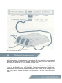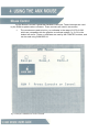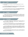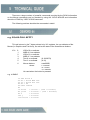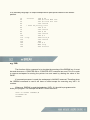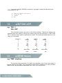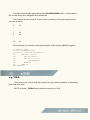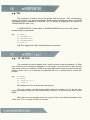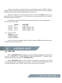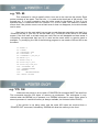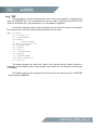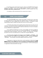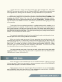
1
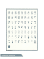
AMX Mouse
USER GUIDE
For the AMX Mouse
& BBC Microcomputer
by
D.S. ELLIOT
© 1984 AMS Ltd: and Elliot Software Ltd:
ADVANCED MEMORY SYSTEMS LIMITED
Green Lane, Appleton, Warrington WA4 5NG
Teleph0ne: 0925 62907
CONTENTS
Page
1 INTRODUCTION............................................
4
1:1
The AMX Mouse package..................................... 4
1.2 Uses of the AMX Mouse.............................................. 5
2 HOW TO USE THIS GUIDE...........................
6
3 SETTING UP................................................... 7
3.1 Fitting the AMX ROM................................................... 7
3.2 Connecting the AMX Mouse........................................ 7
3:3 Technical Requirements.............................................. 9
4 USING THE AMX MOUSE............................ 10
4.1 In existing programs .................................................
4.2 Icons..........................................................................
4.3 Windows....................................................................
4.4 Pointer.......................................................................
11
12
12
12
5 TECHNICAL GUIDE...................................... 14
5.1 OSWORD 64............................................................. 14
5.2 * BREAK.................................................................... 15
5.3 * BUTTONS............................................................... 16
5.4 * DEFINE................................................................... 16
5.5 * DESK...................................................................... 17
5 . 6 * HIDEPOINTER...................................................... 18
5 . 7 * ICON..................................................................... 18
5.8 * MCURSOR ON/OFF............................................... 19
5.9 * MOUSE ON/OFF.................................................... 20
5.10 * MOVEPOINTER.................................................... 20
5.11 *POINTER............................................................... 21
5.12 * POINTER ON/OFF................................................ 21
5.13 * SENSITIVITY........................................................ 22
5:14 * SHOWPOINTER................................................... 22
5.15 * UPDATE................................................................ 23
5:16 * WINDOW.............................................................. 24
5.17 ERROR CODES...................................................... 24
6 ICON DESIGNER.......................................... 25
6.1 Introduction ............................................................... 25
6.2 Using ICON DESIGNER............................................ 26
6.3 ROM icons................................................................. 27
The AMX Mouse together with the accompanying ROM and software represent a
major advance in home computing, making the BBC computer much easier to use for the
average person: Together they represent remarkable value for the BBC owner, and
transform the machine into a much more user friendly device, comparable with much more
expensive machines.
The Mouse may be used with any BBC Model B computer with either cassette or disc
filing systems, and draws its power from the User port.
For the more advanced user, routines contained in the ROM allow programs to be
written in Basic or Assembly language which incorporate many of the latest features
including icons, windows and pointers.
Included in the AMX Mouse package are the AMX Mouse, together with connecting
cable and connector, the AMX ROM, and the AMX Mouse software consisting of an Icon
Designer, MENU program, ROM demo programs, and AMX ART, in disc and cassette form,
together with this and the accompanying AMX ART manual
The AMX Mouse is a 'state of the art' opto mechanical device which incorporates the
latest technical features including three user buttons which are configured normally as
EXECUTE, MOVE, and CANCEL for use in AMX software.
The Mouse comes complete with cable and connector, and is simply plugged into the
BBC User port underneath the front of the computer. The Mouse can be set up as described
in Chapter 4 using *MCURSOR ON to simulate the cursor keys for use with most normal
software, including View and Wordwise, etc. Other more advanced uses of the Mouse are
described in detail later:
The AMX ROM includes commands which allow the user to incorporate advanced
features such as windows, icons, and pointers in BASIC or Assembly language programs as
detailed in Chapters 4 and 5 of this manual.
The accompanying software in disc and cassette form includes two demo programs (
DEMO1, DEMO2), ICON DESIGNER, and AMX ART, an advanced drawing program which
utilises to the full the amazing controllability of the AMX Mouse and the advanced graphics
facilities of the BBC computer to produce results hitherto only possible on expensive
computers.
Together with the accompanying ROM routines, the AMX Mouse may be used with a
wide range of commercial software, and when used with specially written software, the
computer is transformed into an altogether more friendly tool which can easily be used by
non-technical people.
The Mouse is generally recognised as a superior form of pointing device, which is
much more accurate than the ordinary light pen or cheap digitiser. Unlike other devices the
Mouse does not have the inherant tendency to produce spurious co-ordinates, and by use of
the ROM *SENSITIVITY command, can easily be adjusted for response.
Full details of how to use the Mouse are given in Chapter 4, together with example
programs, and a full explanation of the available ROM commands is given in Chapter 5.
The use of icons, and the ICON DESIGNER program are detailed in Chapter 6, and AMX
ART is described in a separate manual:
Throughout this guide several abbreviations have been used, which are listed below:
xcord
ycord
x
y
filename
sx
sy
Graphics x cordinate (0-1279)
Graphics y cordinate (0-1023)
Text x position (0-39/79)
Text y position (0-24/31)
Icon number (0-95)
Disc/Tape filename
X sensitivity of Mouse
Y sensitivity of Mouse
The available commands are described on separate pages, giving the command
syntax (with optional parts in square brackets [ ]), followed by an example giving the
minimum abbreviation: Where alternatives are available they are separated by a diagonal
line '/'. e.g *MOUSE ON/OFF
The ROM can quickly and simply be fitted using only a screwdriver, but when handling
the ROM care must be taken to isolate it from sources of static electricity (e.g: synthetic
clothing, carpets etc.). Take care to touch some earthed surface before removing the ROM
from its protective anti-static foam, and always handle the chip by holding the ENDS, refrain
from touching the pins unnecessarily: The fitting procedure is quite straightforward, but if you
are not confident about fitting the ROM then consult your dealer.
Figure 1: Location of the paged ROM sockets
1.
Unplug the computer from the mains:
2.
Remove the four screws on the BBC Microcomputer marked "FlX"- two are on
the back panel and two on the underside.
3.
Lift off the lid and remove the bolts holding the keyboard in place:
4.
With the computer orientated as for use, ease the keyboard forward to reveal
the Five large ROM sockets as indicated in Fig: 1:
5.
The left hand socket is used exclusively for the Operating System and will
already contain a ROM which must not be moved. The other four sockets are
for the paged ROMs.
6.
The AMX ROM MUST be placed in a high priority socket, (i:e: one to the right)
and preferably number 15 (the furthest right). If a ROM expansion board is
fitted then socket 15 may be reserved for special use, if so then place the AMX
ROM in the highest priority socket possible, but anyway in one of the sockets
12, 13, 14, or 15. Installing the AMX ROM in a lower priority socket will slow
down the response of the mouse.
7.
The pins on the ROM may require gently bending inwards to align them with
the socket:
8.
Insert the ROM into the socket ENSURING THAT THE NOTCH IS AWAY
FROM THE KEYBOARD.
9.
Check that all pins are correctly inserted and none are bent underneath.
10.
Replace the keyboard and lid.
11.
On switching on the message 'AMX Mouse off' should appear underneath "
BBC Computer". This message will not appear if the AMX ROM is placed in a
lower priority socket to any DFS or NFS (if fitted), although the ROM will still
function correctly.
The Mouse simply plugs into the User Port of the BBC. BEFORE CONNECTING
THE MOUSE UNPLUG THE COMPUTER FROM THE MAINS. The cable is then
connected to the socket on the underside of the computer as indicated in fig.2. Care must
be taken to ensure that the cable is inserted the correct way round: To do this pin 1 on the
computer socket, as indicated by the triangle, must match pin 1 on the plug, also indicated
by a triangle, and the locating key fits uppermost into the slot on the port housing.
Fig: 2: Connecting the AMX Mouse
The AMX Mouse is compatible with all other Paged roms tested, as well as with the
6502 2nd processor. Since the Mouse is connected to the only User Port it cannot be used
when other devices are plugged into the port. However only 5 bits of the port, and CB1,CB2
are used: This leaves bits 1,3 and 4 available for other uses.
Two vectors are used by the AMX ROM, namely the EVENT Vector (EVENTV &220,
1) and the KEYBOARD Vector (KEYV &228,9). These vectors cannot be used by other
ROMs as they will automatically disable the Mouse. These vectors can be changed by the
user, if the original contents are stored, and returned to at the end of the intercepting
routine.
As the Mouse is moved it generates hardware interrupts. These interrupts are used
by the ROM to update various counters. These counters are used in two modes:
1.
The counters are used to hold x,y co-ordinates in the range (0-1279,0-1023
which are compatible with the graphics co-ordinate system, i.e. 0,0 is in the
bottom left corner. These co-ordinates are used by the POINTER routines, and
can be read using OSWORD 64.
Fig. 3: Example of *WINDOW and *ICON commands
2.
At certain values (Set by the *SENSITIVITY command see. 5.13) the counters
are reset to zero, and a cursor key code is generated instead. Therefore by
moving the Mouse around, the cursor is moved as if the cursor keys were
being used. This mode is compatible with a wide range of commercial
software including programs such as VIEW and Wordwise:
NOTE: The above two modes are incompatible and cannot be used at the same time.
The first mode is the default on power up, and the second mode is selected by a
*MCURSOR ON command (See. 5.9).
Another function of the ROM is to read the Mouse buttons by intercepting the
keyboard vector. This means that the buttons can be programmed to generate key codes in
a similar method to the keyboard (see 5.3). The Mouse will also respond to negative inkeys
-107,-108,-109 and -129 (which checks all keys on the keyboard):
To allow the generation of displays such as fig.3 several commands (such as
*WINDOW and *ICON) have been included in the ROM: which allow windows and icons to
be quickly drawn on the screen.
The Mouse may be used instead of the normal cursor keys by simply entering
*MOUSE ON and *MCURSOR ON (see 5.8 and 5.9) either before loading or after
depending on the program.
The Mouse buttons may be programmed to simulate three separate keys (see 5.3).
These may be simply the RETURN, COPY, and DELETE keys, for use in editing BASIC
programs, or function keys f0, f1, and f2 in various control and shifted modes. In the latter
mode, they may be programmed as normal function keys using the *KEY command.
In AcornSoft's View wordprocessor it is recommended that a *BUTTONS 4 command
with *FX 228,1 is used. Then by programming the function keys 0,1, and 2 the buttons may
be used to enter the most frequently used commands. For example *KEY0 |!|J would set the
left Mouse button up as "Delete character" (f9):
Icons may be used in either BASIC or Assembly language programs by using the
AMX ROM routines.
If you wish to display a particular icon, then you simply include *ICON i,x,y in your
program: This command displays icon i at TAB(x,y) on the screen. If i is in the range 32-95
then one of the icons in the ROM see 6.3, will be displayed:
If you wish to create and use your own icons, use the ICON DESIGNER program (
see 6.1 later). These icons may then be used by using the *DEFINE command (see 5:4)
which loads the icon set in as numbers 0-31 in addition to the ROM icons:
Windows may be incorporated into your programs by using the *WINDOW command
(see 5.16 later), and this may be used in all modes, although in the non-graphic modes (3,
6, and 7) it simply defines a text window. In the graphics modes, a window is drawn with a
border and this is also defined as a text window: If multiple windows are defined, further
text is printed in the last window defined.
Pointers may be incorporated into your BASIC or Assembly language programs by
using the *POINTER, *HIDEPOINTER, *MOVEPOINTER, *SHOWPOINTER, and
*UPDATE commands (see Section 5 later).
Before any of the above commands can be used, the Rom workspace must be
reserved by executing a *POINTER ON command. Then when the BREAK key is pressed
256 bytes of memory is reserved as Rom workspace and PAGE is increased accordingly.
To allow the BREAK key to be simulated by the program, a *BREAK command is
available: To allow the program to continue therefore, the BREAK key should be
reprogrammed using *KEY 10 to chain the next section of the program. However, if a 2nd
processor is being used, the command *BREAK will not simulate the BREAK key, but will
simply execute the *KEY 10 routine.
The above commands simply initialise the Pointer routines: To display the Pointer on
the screen, the *SHOWPOINTER command is used in conjunction with the *POINTER i1,i2
command (see 5.11 and 5:14 later).
To remove the Pointer from the screen use the * HIDEPOINTER command (see 5.6
later). In order to move the Pointer smoothly over the screen, the * MOVEPOINTER
command is used, which is a combination of both * HIDEPOINTER and * SHOWPOINTER
commands.
If you wish to find out the Mouse position, you may use either the OSWORD 64 or *
UPDATE commands (see 5:1 and 5:15 later).
A small demonstration program using the above commands is shown below!
10 MODE 4
20 *DESK
30 *WINDOW 5,20,30,5, DEMO1
40 VDU 26,23,1,0;0;0;0;
50 REM define pointer as arrow icon
60 *POINTER 80
70 REM display pointer
80 *SHOWPOINTER
90 REPEAT
100 REM erase and redraw pointer
110 *MOVEPOINTER
120 REM loop until button pressed
130 UNTIL NOT INKEY -129
140 REM erase pointer
150 *HIDEPOINTER
160 REM set cursor to Mouse position
170 *UPDATE
180 REM print icon 32 at cursor position
190 *ICON 32
200 *SHOWPOINTER
210 REM wait until. button released
220 REPEAT
230 *MOVEPOINTER
240 UNTIL INKEY-129
250 GOTO 90
The pointer commands *HIDEPOINTER, *SHOWPOINTER and *MOVEPOINTER
only work in the two colour modes 0 and 4. in other modes the error number 168 "illegal
mode" is produced. To use a pointer in the colour modes the following procedures may be
used.
1000
1010
1020
1030
1040
1050
1060
1070
1080
1090
1100
1110
1120
1130
1140
DEF PROCmovepointer
*FX 19
PROChidepointer
DEF PROCshowpointer
LOCAL A%,X%,Y%
A%=64:X%=&70:Y%=0:CALL &FFF1
mx=!&70 AND &FFFF
my=!&72 AND &FFFF
DEF PROChidepointer
GCOL 3,7
MOVE mx-16,my:DRAW mx+16,my
MOVE mx,my-16:DRAW mx,my+16
ENDPROC
There are a large number of powerful commands provided by the ROM. Information
on the Mouse commands can be checked by using the *HELP MOUSE and information
about the ICONS by *HELP ICONS command.
The following sections describe the commands in detail.
e.g. A%=64:CALL &FFF1
This call returns in the 7 bytes pointed to by XY registers, the co-ordinates of the
Mouse (in Graphics and Text form), as well as the state of the three Mouse buttons.
XY+
0
1
LSB of X co-ordinate
MSB of X co-ordinate
2
3
4
5
LSB of Y co-ordinate
MSB of Y co-ordinate
Text X co-ordinate
Text Y co-ordinate
6
Mouse buttons
where
(0-19/39/79)
(0-31)
cme00000
c = cancel
m = move
e = execute
bit reset when the button is pressed
e:g. in BASIC
10 DIM block 6
20 X% = block M0D 256
30 Y% = block DIV 256
40 A% = 64
50 CALL osword
60
70 xcord
= ?block + (256 * block?1)
80 ycord
= block?2 + (256 * block?3)
90 x
= block?4
100 y
= block?5
110 button = block?6
or in assembly language—a simple example which plots points relative to the Mouse
position:
10
.forever
LDA # 64
20
LDX # block MOD 256
30
LDY # block DIV 256
40
JSR osword
50
/ PL0T 69,xcord,ycord
60
LDA # 25
70
JSR oswrch
80
LDA # 69
90
JSR oswrch
100
LDX # 0
110 .loop
LDA block,X
120
JSR oswrch
130
INX
140
CPX # 4
150
BNE loop
160
JMP forever
e.g. *BR.
The function of this command is to simulate the pressing of the BREAK key. It must
be used whenever a *POINTER ON or *POINTER OFF command are used. This is in order
to reserve workspace for storing the pointer icon and mask by altering the value of the
PAGE:
If a second processor is used, the workspace is ALWAYS reserved. Therefore when
the *BREAK command is used it will have no effect except for executing any *KEY 10
routines.
Whenever *BREAK is used the break key (*KEY 10 ) should be programmed to
chain your program. For example the !BOOT file on the disc is:
*KEY 10 CHAIN "!MENU"|M
*P0INTER 0N
*BREAK
If you are using the *BREAK command in a program it should be followed by the
END statement, e.g.
10
20
30
40
*KEY 10 CHAIN "DESIGN"|M
*P0INTER 0N
*BREAK
END
e.g. *BU. 3
*BU. OFF
This command controls the action of the Mouse buttons. These three buttons can
generate three key codes by varying the number given with the command. If *BUTTONS
OFF is used the keys cease to generate the codes. The codes generated depend on the
value of n, see below.
Value of n
0
1
2
3
4
5
6
7
left
Return
f2
sf2
cf2
csf2
3
C
shift cursor
right
middle
Copy
f1
sf1
cf1
csf1
2
B
shift cursor
down
right
Delete
f0
sf0
cf0
csf0
1
A
shift cursor
up
e.g. *DEF. desktop
The purpose of this command is to load in from tape/disc, the 32 user icons (see 4:2)
into the memory of the BBC. The command first opens a file <filename> for input, and then
redefines the 128 user defined characters from 128 to 255, using this file.
This file is automatically generated by the ICON DESIGNER (see 6:1) which allows
the 32 User Icons to be designed using the Mouse.
The format of the file is that of 32 icons, each consisting of 32 bytes organised into
one icon as below:
0
.
16
:
.
7
8
.
23
24
.
.
:
15
.
31
This command is a machine code implementation of the following BASIC program:
10 INPUT file$
20 F% = OPENIN(file$)
30 F0R C% = 252 T0 128 STEP -4
40
F0R E% = 0 T0 3
50
VDU 23,C%+E%
60
FOR D% = 0 TO 7
70
VDU BGET#F%
80
NEXT D%
90
NEXT E%
100 NEXT C%
e.g. *DES.
This command is used to clear the screen to the grey desk top pattern of alternating
black and white dots.
NOTE: In mode 7 *DESK simply clears the screen as in CLS.
e.g. *HI.
This command is used to remove the pointer from the screen. This is achieved by
restoring the screen to its previous contents. These screen contents are stored in the ROM
workspace which is reserved by *POINTER ON. The pointer is displayed on the screen by
*SHOWPOINTER (see 5.14).
If *HIDEPOINTER is used before a *SHOWPOINTER then an error (166, pointer
already hidden) is generated.
e.g.
10
20
30
40
50
M0DE 4
*P0INTER 80
*SH0WP0INTER
*HIDEP0INTER
G0T0 30
N:B. Zero page &70 to &8F are altered by this command:
e.g. * IC. 32,10,5
This command is used to display icon i onto the screen at the text position x,y. Each
icon consists of four characters displayed in a 2x2 square. The text cursor is left in the top
right corner of the icon enabling *ICON to be used again without having to specify the text
position, since if the x,y co-ords are not specified the icon is printed at the current text
position.
e.g:
10
20
30
40
M0DE 4
*DESK
*IC0N 32,10,5
*IC0N 32
Will display two icons of disk drives side by side:
The icon number i, can be in one of two ranges of numbers: 0 to 31 are the User
icons (as designed using the ICON DESIGNER), and 32 to 95 are the icons built into the
ROM:
With User icons the program prints out a group of four user defined characters from
128+i *4 to 131+i *4, where i is the icon number:
If the icon number is from 32 to 95 the Icon definition stored in ROM is used to
redefine ICON 0. Icon 0 is then displayed on the screen as usual. Since icon 0 is constantly
redefined by the ROM it should not be defined as a user icon.
With the computer in its normal state there is a limit of 8 ICONS which can be
defined by the user, there being 0 to 7. Any other icon number between 8 and 31 will give
the same result as icons 0 to 7:
To allow more icons to be defined the character set will have to be exploded and
PAGE set to a new value:
*FX 20,0
*FX 20,1
*FX 20,2
*FX 20,3
Icon No.
0 to 7
0 to 15
0 to 23
0 to 31
New PAGE
no change
PAGE = PAGE + 256
PAGE = PAGE + 512
PAGE = PAGE + 768
e.g: To use 16 icons
*FX 20,1
PAGE=PAGE+256
*DEFINE CHARS
CHAIN "PR0GRAM"
Note: If Computer Concepts Graphic ROM is enabled a *GFX 5 command must be
issued to allow icons to be used.
e.g. *MC. ON
After a *MCURSOR OFF command, moving the Mouse changes the coordinate as
used by OSWORD 64, *SHOWPOINTER, and *MOVEPOINTER. Therefore these
commands must be preceeded by a *MCURSOR OFF.
When *MCURSOR ON is used, instead of generating co-ordinates, the ROM
converts the Mouse's movement into cursor keys. This mode is therefore intended for use
in existing programs such as VIEW, which use the cursor keys for movement.
e.g. *MOU. ON
Whenever the Mouse is to be used several vectors are changed, and interrupts
generated. To use programs which are incompatible with the Mouse a *MOUSE OFF
command should be used. This command stops the AMX ROM from changing this vector or
servicing the interrupts from the User Port.
The *MOUSE ON command should be used whenever the Mouse is needed. There is
no need to use *MOUSE ON before *POINTER ON since *POINTER ON will automatically
switch the Mouse on.
The following commands are available at all times, and are not affected by *MOUSE
ON/OFF.
*ICON
*WINDOW
*DESK
*DEFINE
e.g. *MOV.
This command is used to erase the pointer from the screen, and redraw it at the new
Mouse position. In use this command should be used after a *SHOWPOINTER
e.g.
10
20
30
40
50
60
MODE 4
*POINTER 80
*SHOWPOINTER
REPEAT
*MOVEPOINTER
UNTIL NOT INKEY (-129)
This program will allow the user to move the pointer (an arrow) around the screen by
using the Mouse, until a button or key is pressed.
NB: This command MUST be preceded by a *POINTER ON command. See 5.12.
Zero page &70 to &8F are altered by this command.
e.g. *PO. 80
This command is used to specify which icons are to be used as the pointer: Each
pointer consists of two parts. The first icon, i1, is used as the black part of the pointer. The
second icon, i2, is used inverted to draw the white mask for the pointer: If icon i2 is not
specified then it is assumed that icon number i1+1 is to be used: This method is used to
ensure that if the pointer moves over a black area it does not disappear, but a white border
can be seen.
If an icon is to be used which has not got a mask then you can either use itself (e:g:
*POINTER 80,80) or use icon 95 as the mask (e:g: *POINTER 80,95) which is full white
square. If the icon itself: or a blank mask are used, the icon will disappear on black areas: It
is therefore recommended that icon 95 is used as the mask when no special mask is
available. Try modifying line 100 of the following program to use masks of 80 and 95 to see
the effect.
10 MODE 4
20 *DESK
30 *MCURSOR OFF
40 *BUTTONS 0
50 *WINDOW 5,20,20,5
60 MOVE 0,0
70 MOVE 639,0
80 PLOT 85,0,511
90 PLOT 85,639,511
100 *POINTER 80
110 *SHOWPOINTER
120 REPEAT
130
*MOVEPOINTER
140 UNTIL FALSE
e.g. *PO. ON
Whenever the pointer is to be used a *POINTER ON command MUST be used first.
This command reserves 256 bytes of memory as workspace. This workspace is only
claimed when the BREAK key is pressed, or a *BREAK command is used. (Note: when a
second processor is used this memory is always available, but it doesn't affect PAGE).
If the pointer is not being used, and the extra 256 bytes are required then a
*POINTER OFF command, followed by *BREAK will allow the memory to be used.
e.g. *SE. 2
As the Mouse is moved it generates various interrupts. These interrupts are used to
add/subtract numbers (sx,sy) from the current coordinates. The purpose of the
*SENSITIVITY command is to set the values of sx and sy:
If sy is not used then it is assumed to be the same as sx. The relationship between
sx/sy and the number added to the co.ordinate is 2^sx as shown in table 1. This gives a
very wide range of sensitivities.
sx/sy
0
1
2
3
4
5
6
7
Number added/subtracted (n)
1
2
(MODE 0)
4
(MODE 4)
8
16
32
64
128
Table 1
When a *MCURSOR ON command is used the Mouse doesn't generate coordinates,
but generates cursor keys instead. In this mode the values of sx,sy are used to control how
often these keys are repeated. As the Mouse is moved the co-ordinates are
incremented/decremented (depending on the direction) until it reaches n (as in table 1), the
key is then generated and the relevant co-ordinate set to zero.
e.g. *SH.
This command is used to draw the pointer on the screen using the icons set by
*POINTER i1,i2 (see 5.11). Whatever is under the pointer is stored in the ROM workspace,
which is reserved by *POINTER ON, *BREAK.
It is important that tnis command is used whenever the screen is cleared, and
before *MOVEPOINTER, *HIDEPOINTER commands.
N:B: This command alters zero page &70 to &8F:
e.g. *UP.
This command is used to move the text cursor to the current position of the Mouse (as
read by OSWORD 64): The co-ordinates can then be read using POS and VPOS: Since
these co-ordinates are in text characters, it is not suitable for graphics:
If a window has been defined this command will not return the correct co-ordinates.
To overcome this a VDU 26 (restore default window) must be used.
e:g. 10 MODE 4
20 *POINTER 80
30 *SHOWPOINTER
40 REPEAT
50
*MOVEPOINTER
60 UNTIL NOT INKEY-129
70 *HIDEPOINTER
80 *UPDATE
90 *ICON 32
100 *SHOWPOINTER
110 REPEAT
120 *MOVEPOINTER
130 UNTIL INKEY-129
140 GOTO 40
The above program will allow the Pointer to be moved around: When a button is
pressed icon 32 is drawn at the current position. Note that lines 110-130 wait until the button
is released:
N:B. Before entering this program the Pointer should be switched on by *POINTER
ON and pressing BREAK.
e.g. *WINDOW 1,30,18,1, title
The purpose of this command is to draw a window on the screen. The window has a
border which is especially effective when windows overlap. If a title string is given in the
parameters then it will be printed on the top line of the window, with a horizontal line
beneath it.
The window co-ordinates are specified as text co-ordinates as in a VDU 28
command, i.e. bottom left corner (Ix, by) followed by the top right corner (rx,ty): The range
of these co-ordinates is 0 - 19/39/79 horizontally and 0 - 31 vertically according to the
screen mode.
Nine error codes can be generated by the ROM and are listed below:
164 Insufficient Arguments
165 Illegal icon no:
166 Pointer already hidden
167 BREAK not pressed
168 Illegal mode
169 Pointer switched off
170 Mouse switched off
171 Define file error
254 Bad command
The above errors can be trapped in your program by using an ON ERROR GOTO
command.
The ICON DESIGNER program enables you to define your own icons, which are
numbered 0 to 31, and these occupy the 128 character spaces available in the exploded
character set (see 5.7). The program is loaded from the MENU program by selecting the
appropriate icon and pressing the EXECUTE button followed by a second press when
prompted. Tape users should ensure that the tape is wound to the appropriate position
before loading.
Fig. 4: ICON DESIGNER
To load and run the program direct from tape or disc type *POINTER ON followed by
pressing the < BREAK> key to reserve ROM workspace, followed by typing 'CHAIN "
DESIGN" ' <RETURN> : Incidentally, ICON DESIGNER is a BASIC program which uses
the AMX ROM routines and may be listed.
On loading you will be presented with the screen shown in figure 4:
The ICON DESIGNER screen contains six windows of various sizes, a disc drive
icon and a waste bin icon: Each window has a different function, the largest window used
for designing your icons is labelled with the current icon number: To the right is a small
window which is used to indicate the actual size of the icon you are creating.
At the base of the screen are two windows which will store the icons which you are
working on: The uppermost window is labelled with the filename of the current main set of
icons being used (0-31). The lower window enables an alternate set of icons to be loaded in
for use, and these are numbered 32-63.
As an example the ROM icons are also on the tape/disc, and may be loaded by
moving the pointer over the disc drive icon and pressing EXECUTE: In the MESSAGES
window three prompts will appear, "Load icons", "Load alt.", and "Save icons". To load in
the first 32 rom icons, move the pointer over "Load icons" and press EXECUTE:
You will now be prompted for the filename: Type "R.CHARS1" < RETURN > , and
the first 32 icons will be loaded into the uppermost icon window and the filename will
appear as the title. Now repeat the exercise, selecting "Load alt:", and typing "R.CHARS2"
< RETURN > . The second 32 icons will be loaded into the lower icon store:
To alter an icon, simply move the pointer over the required icon and press and hold
down the MOVE button, dragging the icon into the main icon designing window, releasing
the MOVE button: The selected icon will now be displayed in an enlarged format and the
icon number selected will now appear at the head of the window. The icon will also appear
in original size in the small window to the right.
To alter the icon, simply move the pointer over each enlarged 'dot' and press
EXECUTE to invert the colour of the dot. Pressing EXECUTE again will invert the dot back
to its original colour. Moving over the window, you may create an icon of your choice.
When you are satisfied, simply pick up the icon using the pointer and holding down
the MOVE button, 'drag' it to any of the icon positions in the UPPERMOST icon store: On
releasing the MOVE button, the icon will be stored in the selected position,
OVERWRITING the icon previously stored at that point: REMEMBER, created icons may
only be stored in the UPPER icon store, and must be stored there before going on to any
other operation.
To the right of the icon designing window is a gridded window which enables you to
assemble several icons together to see how they look. Simply pick up the required icons
one by one from any of the two icon stores at the base of the screen, and deposit them in
the required positions on the grid: If you wish you may move them around the grid you
may pick them up and relocate them. If you pick up the wrong icon, simply move over the "
dustbin" icon and release the MOVE button.
You may also assemble a set of icons by combining the main and alternative icons
into the upper icons store, saving under a new filename.
When you wish to create a new set of icons, remember they must be stored in the
uppermost icon store first. To save these, simply move the pointer over the disc drive icon,
press EXECUTE: This will reveal the filing prompts in the MESSAGES window. Select "
Save icons" by moving the pointer over the prompt and pressing EXECUTE: When
prompted, type in your selected filename followed by <RETURN> . Your set of icons will
now be saved onto your current filing system (disc/tape).
You may create as many sets of icons as you wish, taking care to save them under
separate filenames. These may then be used in conjunction with the ROM routines
*DEFINE (see 5:4) and *ICON (see 5.7).
When using the *ICON command with an icon number between 32 and 95, the built
in icons are used. These icons are used in various programs such as ICON DESIGNER
and the MENU program, and other software to follow.
These sixty-four icons are shown in figure 5 and are filed in two set as R.CHARS1
and R.CHARS2: Note that icons 80 to 91 are designed for use with the *POINTER
command and are in pairs, each icon followed by its mask.
Fig: 5: The ROM Icons
NOTES
NOTES
NOTES
NOTES