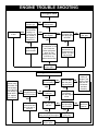
1
ASSEMBLY AND OPERATION MANUAL
Warranty
• DuraTrax™ will warranty this kit for 90 days after the purchase date from defects in materials or workmanship. DuraTrax
will either repair or replace, at no charge, the incorrectly made part.
• Make sure you save the receipt or invoice you were given when you bought your model! It is your proof of purchase
and we must see it before we can honor the warranty.
• To return your Axis for repairs covered under warranty you should send your buggy to:
Hobby Services
1610 Interstate Drive
Champaign, Illinois 61822
Attn: Service Department
Phone: (217) 398-0007 9:00 am - 5:00 pm Central Time M-F
E-mail: [email protected]
Before Building:
We want the building and operating of this vehicle to be a success, so BEFORE removing any parts from the parts bags
please read this manual thoroughly and watch the included video to familiarize yourself with the model. If for any reason
you think this model is not for you, return it to your dealer immediately. PLEASE NOTE: Your hobby dealer cannot accept
a return on any model after assembly has begun.
© Copyright 1999
DTXZ1050 For Kit DTXC0070/DTXD70**
• The engine and exhaust can become very hot. Avoid
touching any of these parts during use and until they
have cooled down.
• Model engine fuel is poisonous. Make sure you read and
follow all of the precautions on the fuel container. Keep
fuel out of the reach of children.
• Model engine fuel is flammable and when ignited has a
flame that is difficult to see. Avoid sparks, flames,
smoking, or any other ignition source when fuel is near.
• The engine emits carbon dioxide just like real cars. Do
not operate this model indoors.
• Before turning on the transmitter, make sure that no one
else is on your frequency.
TABLE OF CONTENTS
Introduction .................................................................................2
Safety Precautions .....................................................................2
Helpful Hints................................................................................2
Stress-Tech™ Parts Guarantee...................................................2
Repair Service.............................................................................3
Specification & Description Changes.......................................3
Screw Information ......................................................................3
Required Items for Completion .................................................3
Tools You Will Need....................................................................3
Finishing the RTR Version.........................................................4
Assembly of the Pre-Built Version............................................6
Preparing the Radio System......................................................6
Radio Installation........................................................................6
Steering Linkage.......................................................................10
Brake and Throttle Linkage .....................................................10
Air Filter and Fuel Tubing Installation ....................................12
Radio Adjustments ...................................................................13
Wing Mounting..........................................................................14
Carburetor Settings ..................................................................15
Breaking in the Engine.............................................................15
Running the Engine..................................................................15
Engine Maintenance .................................................................16
Performance Tuning .................................................................17
Maintenance Tips......................................................................18
Engine Trouble Shooting .........................................................19
HELPFUL HINTS
• Avoid working over a deep pile carpet. If you drop a small
part or screw, it will be difficult to find.
• Place a mat or towel over your work surface. This will
prevent parts from rolling off and will protect the work
surface.
• Avoid running the buggy in cold weather. The plastic and
metal parts can become brittle at low temperatures. In
addition, grease and oil become thick, causing
premature wear and poor performance.
• Test fit all parts before attaching them permanently.
INTRODUCTION
Thank you for purchasing the DuraTrax Axis. This manual
contains the instructions you need to build, operate and
maintain your new nitro R/C buggy. Read over this manual
thoroughly before building or operating the Axis.
STRESS-TECH™ PARTS GUARANTEE
SAFETY PRECAUTIONS
We have engineered the Axis to take the rough and tumble
abuse that makes R/C buggies fun. We are so confident of
the quality and durability of the Stress-Tech™ plastic parts
that we will replace any Stress-Tech plastic part you break
during the first 6 months you own the buggy. Just send in
the part to us and we will send you a Free replacement.
Please see the Axis parts list for the items covered under
the Stress-Tech guarantee.
When the safety precautions are followed, the Axis will
provide years of enjoyment. Use care and good sense at all
times when operating this radio controlled buggy. Failure to
use this vehicle in a safe, sensible manner can result in
injury or damage to property. You and you alone must insure
that the instructions are carefully followed and all safety
precautions are obeyed.
To receive your free replacement part please send the
following to the Hobby Services address listed on the cover
of this manual:
• Do not operate the Axis near people. Spectators should
be behind the driver or at a safe distance away from the
vehicle.
• The engine and exhaust produces quite a bit of noise. If
you are disturbed by the amount of noise this buggy
produces, wear ear protection such as earplugs. Do not
run this vehicle when or where it can disturb others.
•
•
•
•
2
The broken part must be included.
The part number and description of the broken part.
Dated copy of your invoice or purchase receipt.
Your name, phone number and shipping address.
REPAIR SERVICE
REQUIRED ITEMS FOR COMPLETION
Repair service is available anytime.
• After the 90 day warranty, you can still have your Axis
repaired for a small charge by the experts at DuraTrax’s
authorized repair facility, Hobby Services, at the address
listed on the front page of this manual.
To operate the Axis these items are required:
•
•
•
•
•
•
Glow plug starter (Hobbico Hot-Shot 2 -HCAP2520).
Fuel bottle (DuraTrax Kwik-Pit Bottle - DTXP0125)
Fuel (DuraTrax Red Alert fuel - DTXP0520)
Air Filter Oil
Glow plug wrench (DTXR1170)
It is also helpful to have a couple of extra glow plugs
on hand (O.S. #A3 plug - OSMG2690)
• Hobby knife (HCAR0105), #11 blades (HCAR0211)
To speed up the repair process, please follow the
instructions listed below.
1. Under most circumstances return the ENTIRE system:
buggy and radio. The exception would be sending in a
Stress-Tech part. See the instructions under Stress-Tech
Guarantee.
2. Make sure the transmitter is turned off, all batteries are
removed and fuel is drained from the tank.
3. Send written instructions which include: a list of all items
returned, a THOROUGH explanation of the problem, the
service needed and your phone number during the day. If
you expect the repair to be covered under warranty, be
sure to include a proof of date of purchase (your store
receipt or purchase invoice).
4. Also be sure to include your full return address.
SPECIFICATION & DESCRIPTION CHANGES
All pictures, descriptions and specifications found in this
instruction manual are subject to change without notice.
DuraTrax maintains no responsibility for inadvertent errors
in this manual.
(All of these items are available in a Nitro Starter Pack
from DuraTrax - DTXP0200).
For the Pre-Built version of the Axis, you will also need:
• 2-channel radio with (1) standard servo and (1) high
torque (70+ oz./in.) servo (for steering).
• (12) “AA” batteries - (4) for the receiver and (8) for the
transmitter.
• Small bottle of thread locking compound (GPMR6060).
SCREW INFORMATION
Do not use too much force when tightening self-tapping
screws into plastic. Overtightening will cause the threads in
the plastic to strip. We recommend that you stop turning a
self-tapping screw when you feel some resistance as the
head of the screw comes in contact with the plastic. Avoid
using powered screwdrivers when assembling this kit. They
tend to overtighten the screws. Do not use thread locking
compound on any self-tapping screws. The thread locking
compound may damage the plastic. IMPORTANT: Use
thread lock on any fastener that is threaded into metal or
fastened with a nut. Vibration from the engine will cause the
screws to loosen if thread locking compound is not used.
To assemble the Pre-built version (DTXC0070), you will
need the following tools:
M3x14
Self-Tapping
Screw
M3x14 Screw
3mm
14mm
TOOLS YOU WILL NEED
•
•
•
•
•
3mm
14mm
3
Phillips head screwdriver
Flat blade screwdriver
Needle-nose pliers
Wire cutters or diagonal cutters (HCAR0630)
Hobby knife (HCAR0105), #11 blades (HCAR0211)
FINISHING THE AXIS RTR VERSION (DTXD70**)
❏ 1. Remove the buggy, transmitter and parts from
the box.
ANTENNA INSTALLATION
❏ 4. Press the “L” shaped boot onto the bottom housing
of the air filter. Using one of the included tie-straps,
secure the boot onto the bottom housing. Cut off the
excess portion of the tie-strap. Screw the bottom and
outer filter housing together. Note: Overtightening will
strip the threads.
❏ 2. Remove the twist-tie from the receiver antenna
wire. The receiver wire looks like a bundled thin wire
that is attached to the receiver. Run the length of the
antenna wire through your fingers to help straighten
the wire out, this will make it easier to get the wire
through the tube. Remove the antenna tube from the
decal bag. Slide the antenna wire through the antenna
tube. Do not coil or cut the antenna. Cut two pieces
of fuel tubing 1/8" wide and slide them over the outside
of the antenna tube and wire. This is to help hold the
antenna tube on and avoid getting the antenna wire
cut in a roll over. Note the placement of the tubing on
the antenna tube.
❏ 5. Place the air filter onto the carburetor. Using the
remaining included tie-strap, secure the air filter to the
carburetor. Cut the excess portion of the tie-strap off to
avoid interference.
AIR FILTER INSTALLATION
WING MOUNTING
❏ 3. Remove the air filter parts from the parts pack. ❏ 6. Locate the pre-drilled wing and place it onto the
Slide the large rubber O-ring around the threads of the
outer housing. The O-ring will help seal the air filter
together. Soak the air cleaner element with an air filter
oil, light machine oil, or, in a pinch, shock oil.
Thoroughly soak the foam element and squeeze out
the excess. Then install the filter element into the
plastic outer housing.
wing mount plate. Make sure that holes in the wing line
up with the wing mount plate. Place a tapered black
plastic washer over each of the two holes. Then insert
a 3x12mm screw through the washer and wing into the
wing support. (Make sure not to overtighten the
screws holding the wing on to avoid stripping the
holes in the wing support).
4
RADIO SETUP
❏ 10. Slide open the battery door on the bottom of the
transmitter and remove the transmitter battery holder.
Place 8 “AA” batteries (included) into the holder in the
configuration molded into the plastic on the battery
holder. Re-install the transmitter battery holder into the
transmitter and re-install the battery door.
❏ 7. Remove the receiver battery holder from the
radio box. Install (4) “AA” batteries (included) into the
battery holder in the configuration molded into the
battery holder.
❏ 11. Turn on the transmitter using the switch on the
back (see photo with step 9). The green light on the side
of the transmitter should light up. If there is no light on,
turn the transmitter off and check to ensure that the
battery holder is making contact with the copper contact
on the inside of the battery compartment. Make sure the
batteries are installed correctly. Turn the transmitter on
and check for the green indicator light. If the green light
appears, turn off the transmitter.
❏ 8. Re-install the receiver battery into the radio box.
Note the placement of the receiver battery in the box.
Make sure that the receiver switch is in the “off”
position. Plug the connector on the receiver battery
into the socket on the receiver switch. Wrap the
receiver with the included foam rubber (if desired,
secure with a rubber band, not included) to help
reduce possible radio interference from vibration.
❏ 12. Remove the plastic from the outside of the body.
Apply the decals to the body and wing if desired.
❏ 13. Remove the body clips from the parts bag.
Place the body onto the body mounts. On each body
mount place a body clip.
❏ 9. Remove the transmitter antenna from the holder You are ready to go! Watch the video one more time and
turn to page 15 for performance and maintenance tips.
and screw it into the hole on top of the transmitter.
5
ASSEMBLY OF THE AXIS PRE-BUILT VERSION (DTXC0070)
PREPARING THE RADIO SYSTEM
1 4-AA Batteries
7 Receiver
4 Antenna
Switch
Before installing the radio system in the
pre-built DuraTrax Axis read the
manufacturer’s instructions manual and
follow the instructions shown below.
1. Install the batteries in the transmitter and
the receiver battery holders.
Receiver Battery Holder
2. Extend the transmitter antenna.
3 Receiver
2 Antenna
Throttle Servo
Transmitter
Steering
Servo
6
Servo Arm
5
3. Connect the steering servo, throttle servo
and receiver battery to the receiver.
4. Extend the receiver antenna.
5. Adjust the servo trims of the transmitter to
the neutral position.
6. Switch on the transmitter.
7. Switch on the receiver.
8
8. Operate the steering and throttle control.
Make sure the servo arms move in
proportion to the movement of the
steering wheel and throttle trigger.
9. Switch off the receiver, then the transmitter.
1 8-AA Batteries
❏ 1. Remove the Axis buggy and the transmitter from
the box.
RADIO INSTALLATION
❏ 3. Install the receiver on/off switch. Remove the two
screws from the face plate of the on/off switch and
remove the face plate. The switch should be in the
“OFF” position. Insert the on/off switch up through the
bottom of the radio plate. Then place the face plate
over the top of the on/off switch and place the two
screws back through the face plate into the on/off
switch. Be sure to reinstall the face plate with the
“OFF” position next to the switch button. Run both
wires from the on/off switch through the hole in the
side of the radio box.
❏ 2. Remove the radio tray from the chassis by
removing the (8) 3x15mm flat head self tapping
screws from the bottom of the chassis.
6
❏ 4. Use a hobby knife or diagonal cutters to remove
❏ 7. Place the high torque steering servo into the
the servo mounting blocks from the radio tray. Make
sure all of the flashing is removed from inside the
servo compartment to assure a proper servo fit. Save
the servo mounting blocks.
radio tray. Note the direction of the servo spline
when installing. Run the servo lead through the hole
in the side of the radio box.
❏ 5. Place the standard throttle servo into the radio
tray. Note: Notice the direction of the servo spline
when installing. Run the servo lead through the hole
in the side of the radio box.
❏ 8. Mount the servo to the radio tray using four
mounting screws included with the radio system. Use
the other mounting block that you cut out of the radio tray
in step 4 and place it against the under side of the radio
tray under the slotted holes. The screws should go
through the servo, the radio tray and into the servo
mounting block. Note: Make sure to use the mounting
block on the end with the slotted mounting holes.
❏ 6. Mount the servo to the radio tray using four
mounting screws included with the radio system. Use
one of the servo mounting blocks that you cut out of
the radio tray in step 4 and place it against the under
side of the radio tray under the slotted holes. The
screws should go through the servo, the radio tray and
into the servo mounting block. Note: Make sure to
use the servo mounting block on the end with the
slotted mounting holes.
❏ 9. Cut two of the arms off the throttle servo horn by
scoring both sides of the arm with a hobby knife and
snapping off the arms with pliers.
7
❏ 10. Install the servo horn onto the throttle servo, ❏ 13. Route the wires and connectors for the switch
note the direction of the servo horn. Secure the
horn to the servo with the screw included with the
radio system.
and two servos through the hole in the radio box. Cut
a piece of foam the size of the radio box and place it
in the bottom for all of the equipment to set on. Make
sure that all of the wires coming into the radio box are
on top of the foam. This is to help prevent vibration
damage to the receiver.
❏ 11. Remove three of the arms off the steering servo
❏ 14. Install the receiver into the radio box and route
horn as shown.
the antenna wire through the same hole the servo
leads come in. Run the antenna wire up through the
antenna mount hole.
❏ 12. Install the servo horn onto the steering servo, ❏ 15. Plug the steering servo, throttle servo and
note the direction of the servo horn. Secure the
horn to the servo with the screw included with the
radio system.
switch into the receiver. See your radio instructions to
determine which channel is steering and which is
throttle. The switch plugs into the battery socket.
8
❏ 19. Install the receiver into the receiver box as
❏ 16. Install 4 “AA” batteries into the receiver battery shown. Make sure all of the wires are out from under
the receiver so that it will properly fit into the radio box.
holder in the configuration molded into the battery
holder included with the radio system.
❏ 20. Cut the left over foam into small pieces and
place them around the receiver and battery to help
secure them into place. Then slide the radio box cover
back onto the radio box.
❏ 17. Install the receiver battery into the radio box.
Note the placement of the receiver battery in the box.
Connect the receiver battery to the remaining end of
the on/off switch.
❏ 21. Run the length of the antenna wire through your
fingers to help straighten the wire out, this will make it
easier to get the wire through the tube. Slide the
antenna wire through the antenna tube. Frequently,
there will be leftover wire through the antenna tube
(Do not cut or coil the antenna!) Cut two pieces of
fuel tubing 1/8" wide and slide them over the outside
of the antenna tube and wire. This is to help hold the
antenna tube on and avoid getting the antenna wire
cut in a roll over. Note the placement of the tubing on
the antenna tube.
❏ 18. Cut a 2" x 7" (50 x 175mm) piece of the included
foam and wrap it around the receiver. If desired, you can
wrap a small rubber band (not included) around the
outside of the foam to secure it in place for added security.
9
❏ 26. Loosen the screw in the bottom of the steering
❏ 22. Re-install the radio box back onto the chassis. arm on the servo saver enough for the linkage rod to
slide through the metal rod connector.
Use the (8) 3x15mm flathead self tapping screws that
you removed earlier to secure the radio box back onto
the chassis. Refer to the picture in step 2 on page 6.
STEERING LINKAGE
❏ 27. Remove the screw from the steering servo horn.
Slide the steering linkage rod through the hole in the
linkage rod connector in the steering arm. Place the
servo horn back onto the servo. When placing the
horn onto the servo, the horn and the steering arm
should be parallel as shown in the photo. Note: Do
not screw the servo horn down yet, the servos will
need to be centered after assembly is completed.
❏ 23. Remove one of the three prebent linkage rods
with a z-bend at the end of it from the linkage bag.
Note all of the prebent rods are the same.
BRAKE AND THROTTLE LINKAGE
❏ 24. Remove the servo horn from steering servo.
Enlarge the hole 3/4" (19mm) away from the center of
the horn with a 5/64" (2mm) drill or a hobby knife.
❏ 28. From the linkage bag remove the two remaining
prebent linkage rods with z-bends at one end, the
straight throttle wire, (6) 2mm rod collars, (6) 2mm set
screws, (1) throttle linkage spring, (1) rod connector,
(1) 2mm nut and (1) plastic ball cup. Also cut (2) 1/4"
pieces of fuel tubing from the fuel tubing included with
the kit.
❏ 25. Install the z-bend end of the linkage rod into the
servo horn from the bottom as shown.
10
❏ 29. Remove the servo horn from the throttle servo. ❏ 32. Install the set screw into two of the rod collars.
Enlarge the two farthest holes at one end of the horn
and the farthest hole on the other end with a 5/64"
(2mm) drill or a hobby knife.
Place one rod collar onto both of the prebent linkage
rods. Note: Do not tighten the set screws all the
way down yet, the linkage will be adjusted later.
Rod Connector
❏ 30. Install the rod connector into the top of the horn
at the end with the single enlarged hole. Apply a small
amount of thread locking compound onto the threads
of the rod connector, then thread on the 2mm nut. Do
not overtighten the nut, the rod connector must be
able to swivel freely.
❏ 33. Re-install the servo horn onto the servo. Slide the
brake linkage rods through the brake levers as shown.
❏ 34. Screw the plastic ball cup onto the throttle
linkage wire. Install one rod collar onto the linkage rod,
then slide on the throttle linkage spring. Insert the
throttle linkage through the rod connector as shown.
Note: Do not tighten the set screw in the rod collar
down, adjustments will be made later.
❏ 31. Install the two linkage rods with the z-bends at
one end of them into the two enlarged holes at the
opposite end from the rod connector.
11
❏ 35. Snap the ball cup onto the throttle. Install a
second rod collar onto the throttle linkage so that it fits
against the rod connector. Note: Do not tighten the
set screw in the rod collar, the linkage will be
adjusted later.
❏ 39.Install one end of the 4" (100mm) piece of fuel
tubing onto the nipple next to the fuel tank lid and the
other end on the nipple on the tuned pipe.
❏ 36. Slide a 1/4" piece of fuel tubing over each of the
brake linkage rods. Then install a rod collar onto each
of the two rods. Note: Do not tighten the set screw
in the rod collars, the linkage will be adjusted later.
AIR FILTER AND FUEL TUBING
INSTALLATION
❏ 40. Assemble the air filter. Slide the large rubber O❏ 37. Locate the fuel tubing included with the kit. Cut ring around the threads of the outer housing. The Oa 6" (150mm) piece to go from the fuel tank to the
carburetor and a 4" (100mm) piece to go from the fuel
tank to the pressure nipple on the tuned pipe.
ring will help seal the air filter together.
❏ 41. Soak the air cleaner element with an air filter oil,
light machine oil, or in a pinch, shock oil (not included).
Thoroughly soak the foam element and squeeze out
the excess. Then install the filter element into the
plastic outer housing. Install the filter element into the
plastic outer housing.
❏ 38.Install one end of the 6" (150mm) piece of fuel
tubing onto the rotatable nipple on the rear of the fuel
tank and the other end onto the nipple on the carburetor.
12
RADIO ADJUSTMENTS
❏ 45. Turn on the transmitter and receiver.
❏ 42. Press the “L” shaped boot onto the bottom
housing of the air filter. Using one of the included tiestraps, secure the boot onto the bottom housing. Cut
the excess portion of the tie-strap to avoid interference.
❏ 46. Slide the rod collars and fuel tubing that engage
the brakes so that when the car is at an idle the brakes
are slightly on. Test this by rolling the Axis on a flat
table or the floor and applying the brakes using the
transmitter. Move the rod collars on the other side of
the brake levers so that they will push the levers back
when accelerating.
❏ 43. Screw the bottom and main filter housing
together. Note: Overtightening will strip the threads.
❏ 47. Tighten the rod collar that retains the throttle
❏ 44. Place the air filter onto the carburetor. Using the spring so that the spring cannot move back and forth
but not so much that the spring is tight. The rod collar
at the other end of the throttle linkage should be
tightened against the rod connector as shown.
remaining included tie-strap, secure the air filter to the
carburetor. Cut the excess portion of the tie-strap off to
avoid interference.
13
WING MOUNTING
❏ 48. Remove the throttle and steering servo horns
from the servos. Turn on the transmitter, then turn on
the receiver. Center the trims on the transmitter (see
your radio instructions). Place the horns back onto the
servos as shown. Make sure the wheels are pointing
straight ahead and the throttle should be at an idle
position. Install the servo horn screws once the horns
have been centered. Use the trims on the radio to fine
tune the centering of the tires and the idle of the
engine. When finished trimming, turn the receiver and
transmitter off.
❏ 49. Locate the pre-drilled wing and place it onto the
wing support. Make sure that the holes in the wing line
up with the wing support. Place a tapered black plastic
washer over each of the two holes. Then insert a
3x12mm screw through the washer and wing into the
wing support. (Make sure not to overtighten the
screws holding the wing on to avoid stripping the
holes in the wing support).
❏ 50. Remove the plastic from the outside of the body.
Apply the decals if desired.
❏ 51. Remove the body clips from the parts bag.
Place the body onto the body mounts. On each body
mount place a body clip.
14
CARBURETOR SETTINGS
BREAKING IN THE ENGINE
To insure long life and good performance from your
Torq .21 engine, you MUST break-in the engine. The
break-in period is critical for long life of the internal
parts of the engine. This should be done over the first
5 or 6 tanks of fuel. Be sure to watch the engine tuning
video that came with this kit.
Some Things To Remember During Break-In:
1. Run with the body off. This will keep the engine cooler.
2. Keep the air cleaner on at ALL times.
3. Run on a smooth, hard surface. An empty parking
lot is perfect.
4. Use the same fuel that you will use for normal running.
5. Resist the urge to accelerate and decelerate the
buggy quickly.
6. Break-in puts stress on the glow plug and you can
burn it out during break-in. Make sure you have an
extra plug or two on hand.
7. Do NOT overheat the engine. You can check the
head temperature by using one of the temperature
gauges that are available or by putting a drop of
water on the top of the cylinder head. If the water
boils away immediately, shut off the engine and
allow it to cool. If it takes more than 10 seconds to
boil away, the engine is at proper running
temperature for break-in.
The High-Speed Needle
The “high-speed” needle is sticking up from the side of
the carb. It is located in the brass housing, just above
the fuel inlet. It controls the fuel to air mixture of the
carb. The needle is pre-set for break-in from the
factory at 3 turns out from the fully closed position of
the carb. Once the engine is broken-in, the high-speed
needle would typically run from 2-1/2 to 3 turns out
from closed, depending on the weather, humidity and
altitude above sea level. To richen turn the needle
counterclockwise, to lean turn the needle clockwise.
RUNNING THE ENGINE
The Low-Speed Needle
The “low-speed” needle is the screw in the carb body,
opposite the throttle arm. It controls the fuel to air
mixture at low throttle settings. There is a simple way
of adjusting the low-speed needle correctly called the
“pinch test.” With the engine at idle, pinch the fuel line
and listen to how the engine speeds up or slows down.
If the engine increases its speed for about 2 or 3
seconds and then loses speed, the needle is set
correctly. If the engine loses RPM quickly, it is set too
lean and the low-speed needle needs to be opened
(counterclockwise) to richen the mixture. Pinch again
to check the mixture. If the engine takes longer than 4
seconds to slow down, lean (clockwise) the low-speed
needle and then pinch again to check the mixture.
Before running the engine, read the manual and watch
the engine video that came with this kit.
There are several simple steps to starting the engine:
1. Install a glow plug if one is not in your engine. This
threads into the top of the cylinder head.
2. Fill the tank almost to the top. Leave a little air at the
top of the tank.
3. Prime the engine by turning the flywheel on the
engine. Watch the fuel go through the line and
when it gets to the carburetor, turn the flywheel one
more full revolution.
4. Open the high speed needle valve exactly 3 turns
out (counterclockwise) from fully closed. The
high-speed needle is sticking up from the
carburetor inside the brass housing. All of the
carburetor settings are adjusted with a flat bladed
screwdriver. If you have previously run the buggy,
keep the same needle valve setting that you used
on your last run.
5. Start the engine by pulling the recoil - Use short,
quick pulls. DO NOT pull the recoil starter’s string to
the end. You only need 10 to 12 inches of pull to
start the engine.
The Throttle Stop Screw
On the front of the carburetor, there is a black screw.
This is called the idle stop screw. This increases or
decreases the idle RPM without changing the fuel to
air mixture. The barrel should be approximately
1.5mm (between 1/32" and 1/16") from fully closed.
15
5. After a minute or two of running, make sure the
engine is not overheating by putting a drop of
water on the cylinder head and watching it boil
away. If it boils away within 10 seconds, stop the
engine and allow it to cool. Open the high-speed
needle around a 1/4 turn before starting again.
This is a good habit to get into every time you run
to ensure that the engine does not overheat during
any run. Looking at the smoke that comes out the
exhaust is also an indicator of how rich or lean the
engine is running. If there is a good amount of
smoke coming out of the exhaust, then chances
are good that you are running rich.
6. Run the buggy back and forth at a medium speed
until the tank is almost out of fuel. Do not allow the
tank to run out of fuel. This leans out the engine
and can cause overheating (See How To Stop
Your Engine).
7. Stop the engine and allow the engine to cool
before the second tank. This normally takes
around 10 minutes.
If the engine does not start after several pulls,
sometimes it is helpful to start the engine at around
half throttle. Have a friend pull back on the throttle
some while you start the engine. This may be an
indicator that the low speed needle setting needs to be
adjusted. When the engine starts, immediately return
the throttle to idle. If this is not done the engine can
over-rev and cause engine damage. If the engine is
difficult to turn over with the recoil starter,
especially if it is brand new, loosen the glow plug
a half turn before starting the engine. This allows
some compression to escape, but the engine will
still start. Make sure you tighten the glow plug
after the engine starts. If the recoil starter is still
difficult to pull, the engine is flooded – there is too
much fuel inside the engine. Remove the glow plug
and air cleaner, then turn the engine upside down and
pull the recoil 5 or 6 times. This will clear the engine of
fuel, and you will notice the recoil pulls easier. Replace
the glow plug and repeat the starting procedure.
Fuels
Use fuels that are specially formulated for car and
truck engines. DuraTrax Red Alert fuel is specially
formulated for buggy engines like the Torq .21.
Tanks 2-6
Turn in the needle valve (clockwise) around 1/12 turn
from the previous setting. Run the buggy back and
forth. You should notice that the buggy will perform
better during each run. Stop the buggy periodically to
check for overheating. If it is too hot, stop the engine.
Wait for it to cool, then open up the needle valve and
restart. After the 6th tank, you should be near to the
peak performance of the engine.
How To Stop Your Engine
You may have been wondering how to stop the
engine. All you have to do is pinch the fuel line that
runs to the carburetor and from the bottom of the fuel
tank. Pinching this will restrict the fuel flow and the
engine will quit within a few seconds. You can also
touch the flywheel with the tip of your shoe through the
hole in the bottom of the chassis.
ENGINE MAINTENANCE
The First Tank
Your first tank of fuel should be running the buggy at a
very rich high-speed needle valve setting. This allows
the fuel to carry as much oil as possible into the engine
to lubricate the internal parts during the break-in.
Ten Ways To Ensure A Long Life From Your Engine:
1. Keep your engine clean. Dirt will act as insulation
on an engine. It will not be able to shed heat as
easily. Use a good air filter to keep dirt out of your
engine and clean it often.
2. Do not over-lean your engine.
3. Do not run your engine with little or no load. Don’t
throttle up the engine to full throttle when the
wheels are not in contact with the ground.
4. Do not overheat the engine. This goes along with
keeping it clean and not over-leaning the engine.
5. Do not use a fuel with a low oil content. Make sure
you use a fuel from a reputable manufacturer,
such as DuraTrax Red Alert.
6. Avoid using old fuels in the engine. Always run all of
the fuel out of the engine. After running for the day,
use an after-run oil and work it into the engine by
turning the flywheel or pulling the engine recoil slowly.
7. Do not use a fuel with a nitromethane (often called
nitro) content over 20%.
1. Open the needle valve 3 turns from fully closed
(counterclockwise). This is factory set already, but
check it to make sure. When closing the highspeed needle, close the needle until you feel some
resistance. DO NOT overtighten or you will
damage the engine.
2. Start the engine.
3. Once the engine is started, open the high-speed
needle valve around 1/8 turn at a time, finding the
setting where the engine just barely runs. This
may take a few times adjusting the needle, running
the buggy away from you and back, then adjusting
the needle. The buggy will perform sluggishly and
stall from time to time - that is normal.
4. Run the buggy back and forth at medium speeds,
slowly accelerating and decelerating the buggy.
16
8. Do not scratch the piston or cylinder sleeve. Avoid
jamming something into the exhaust port when
removing or re-installing the clutch or flywheel.
Use a special tool called a crankshaft locking tool,
which is installed in the glow plug hole.
9. Do not use silicone sealer on the engine joints.
Silicone sealer contains acetic acid, which is
corrosive if it gets inside your engine.
10. Do not allow any water inside the engine. This
sounds easy, but temperature changes can cause
condensation inside the engine. This is a good
reason to use an after-run oil. Store your engine
inside the house, not in a garage or shed where
there will be temperature extremes.
To keep dirt out of the engine, use an inline fuel filter
on the fuel line running from the fuel tank to the
carburetor. Dirt can get caught in the needle seat and
cause an inconsistent running engine. If you suspect
that some dirt has lodged itself in the carb, remove the
needles and clean the carb with denatured alcohol or
fuel. It can help to use compressed air to blow out the
fuel passages as well. Dirt can get into your carburetor
and engine through the air filter. Ensure that your air
cleaner has a good seal to the top of the carb.
Periodically wash the air cleaner foam element and reoil the filter. Any air cleaner that has a torn element or
a bad seal should be replaced immediately.
If you are having problems with your engine
consult the engine troubleshooting flow chart on
page 19. The following are some potential
problems.
Overheating
One of the worst things you can do to your engine is
overheat it. The oils that lubricate the engine are
carried in the fuel. If your engine is set too lean, there
will not be enough oil in the engine to lubricate the
internal parts. This will cause premature wear in the
engine and cause damage. We have talked about
overheating in other parts of this manual, but we want
to stress the proper techniques to check for
overheating. The easiest way of checking the
temperature of the cylinder head is using one of the
available temperature gauges. This will give you a
direct reading of the cylinder head temperature. Do not
let the head temperature exceed 220° Fahrenheit
(104° Celsius). Another way of checking the head
temperature is to put a drop of water on the cylinder
head. If it boils away within 10 seconds, the high-speed
needle is set too lean. If the water boils away in
around 15 seconds, the engine is within proper operating
temperatures. If the water boils away longer than 15
seconds, the mixture is set rich which is preferable
when breaking in the engine. Otherwise lean the
mixture some and retest after a minute of running.
Glow Plug
The glow plug is an item that will wear out and need
replacement from time to time. It is a good idea to
remove the glow plug before your first run, heat it and
see how well it glows. You should see a bright orange
glow from the filament. If a coil or two will not glow or
the plug will not glow at all, replace the plug. If the
engine quits when you remove the glow starter, the
plug might need to be changed, although this may be
because you are running too rich and need to screw in
your high-speed needle some. Look at the glow plug
when you are running the engine. If you see some
bubbles coming from around the plug, replace the
glow plug (copper) gasket, or both the plug and
gasket. The only real way to test a glow plug is to
replace it. Make sure you have a spare plug or two on
hand every time that you run the Axis.
Fuel
Fuel can go bad. The main ingredient in model fuel is
methanol, which is basically an alcohol. Alcohols can
absorb water out of the air, so keep your fuel jug
capped at all times. Store your fuel out of the sunlight
and in a cool place. Bad fuel is one of the most difficult
problems to diagnose in engines. If you have tried
everything you can think of to remedy an engine that
is not running correctly, try using some fresh fuel.
PERFORMANCE TUNING
Ride Height: This refers to the clearance between the
ground and the chassis, both at the front and the back
of the buggy. The general rule is to have the
suspension arms perfectly level when the car is at
rest. To determine the ride height, drop the buggy from
around 6"-12" above flat ground. Drop the buggy,
making sure it drops flat. Check where the suspension
arms come to rest. You can adjust ride by moving the
spring adjusters on the shock, which are at the top of
each shock spring, until the arms are level after the
drop test.
Fuel line is susceptible to pinhole leaks. You cannot see
the hole in the fuel line, but if you see air bubbles in the
line going to the carburetor, replace the fuel line. Another
symptom of a leak in the fuel line is a surging engine. The
properly tuned engine will surge when the air bubbles hit
the carb. It is basically leaning out the mixture.
17
expense of steering response and the car will tend to roll
more. In general, shock oils between 20 and 40 weight
will be best for your buggy. You should experiment some
to see what oils work best for your track and driving style.
Shock springs affect the rate that the suspension
rebounds from a bump. We have supplied soft springs
that work under most conditions. Pre-load on the springs
means that the springs are already compressed some
so that the suspension will rebound faster. Sometimes
you will want to pre-load one side when the track has
turns all or mostly in one direction, for instance an oval
track. It will also increase the ride height.
Toe-In/Toe-Out: This refers to the angle of the front
tires when viewed from above when the suspension
arms are level. If the fronts of the tires angle in, it is
called “toe-in” and if the fronts of the tires angle out, it
is called “toe-out.” This is adjusted by lengthening or
shortening the steering rods - the rods that run
between the front hub and the servo saver. Normally a
small amount of toe-in is used to make the buggy track
straight at high speed. Too much toe-in will make the
buggy difficult to turn as well as reduce the overall top
speed because of tire scrub. Sometimes a small
amount of toe-out will be used to help the steering. As
a general rule use a small amount of toe-in.
MAINTENANCE TIPS
Before Each Run
• Check for loosened screws on the buggy. Engine
vibration will loosen some of the screws, particularly
in the engine mount area. Use thread lock on screws
that thread into metal parts or use a metal nut.
• Inspect the air cleaner for a torn or damaged
element. Also look for dirt in the air cleaner element
and wash it if necessary.
• Check the suspension and drive train for binding.
• Inspect all of the wires for damage. Also check the
connectors to make sure all of them are tight and in
the proper place.
• Check the fuel tank and fuel lines for leaks.
• Before starting the engine, turn on the radio and
make sure the servos move easily and in the right
direction.
• Before running always check the condition of your
radio system batteries and replace/recharge if
necessary.
Camber: Camber is the angle of the tops of the tires
when viewed from the front. Negative camber is when
the tops of the tires are angled towards the center of
the buggy. Positive camber is where the tops of the
tires are angled away from the center of the buggy.
Positive camber is very rarely used, if ever. A small
amount of rear negative camber is helpful to increase
traction in the rear. Negative camber at the front will
increase stability. Camber adjustments can be made
on the Axis by turning the “camber rods,” which are the
upper links on the suspension. Lengthening the
camber rod will add positive camber and shortening
the camber rod will add negative camber.
After Each Run
• Drain the fuel tank of any leftover fuel. DO NOT
return it to your fuel jug.
• Put some after-run oil in the carb and turn the
flywheel several times to work the oil into the
engine. This will protect the engine from rusting,
especially when stored for a long period of time.
• Check again for loosened screws.
• CLEAN the buggy. Wipe off any oils that have
collected on the chassis, engine end exhaust. Oils
will attract dirt on the next run.
Shocks: Changes in shock oils, springs, and pre-load on
the springs can dramatically change the way the car
handles. A thicker shock oil will make the buggy turn
faster but reduces overall traction and handling over
bumpy surfaces. Thinner oil will increase traction at the
Inch Scale
0"
0
1"
10 20 30 40
Metric Scale (mm)
2"
50
3"
60
70
80
4"
90
18
5"
6"
7"
100 110 120 130 140 150 160 170 180
ENGINE TROUBLE SHOOTING
The engine starts
It should be
ready to go.
Clear the engine YES
of fuel.
Is the high
speed needle
setting 1 to
1-1/2 turns out
from closed (if
the engine is
broken-in?)
YES
Does it run
continuously?
NO
YES Is fuel getting to
the engine?
YES
NO
Does the engine
quit when the
glow plug clip is
removed?
YES
Replace the
glow plug.
NO
NO
Check for clogging in
the carburetor or fuel
line. Press the
primer pump and
check for fuel
spraying out of the
fuel line. If so,
replace the fuel line.
Reset the high
speed needle.
Check that the
pressure line is
connected to the
muffler. The fuel
may be bad.
Try starting the
engine again.
The engine does not start
Press the
primer pump
and check for
fuel spraying
out of the fuel
line through a
small hole. If
so, replace
the fuel line.
Does the engine
turn over easily?
NO
YES
NO
Is foreign matter
clogging the fuel
tank or fuel line?
YES
Remove the
obstruction from
the fuel tank or
fuel line.
NO
YES
The engine may
be flooded.
Clear the engine
of fuel.
Is fuel in the
fuel line?
YES
Is the glow plug
red hot?
Does the engine
turn over easily NO
with the glow
plug removed?
NO
Is the battery for
the glow plug
clip charged?
YES
YES
Check the high speed needle
setting and prime the engine.
Try starting the
engine again.
19
Check that
nothing is
caught in the
engine. Check
that the the
pull starter
operates
smoothly.
Replace the
glow plug.
NO
Charge or
replace the
batteries.
RECOMMENDED ACCESSORIES
DuraTrax 4-Shoe Clutch Kit
DuraTrax Street Traction™ Tires
DuraTrax Kwik-Pit™ 500cc Fuel Bottle
Tweak your Axis for amazing acceleration!
This kit increases surface area compared to 3shoe clutch designs for an improved clutch
bell grip. Requires bearings (DTXC1535) and
clutch
bells
(DTXC2521-DTXC2526).
DTXC2542
These front/rear tires for your 1/8 scale
machine feature a flat radial tread design
that's ideally suited for action on concrete,
asphalt and hard-packed dirt surfaces. Sold in
pairs. DTXC8270
Fast, clean pit stops are as close as the KwikPit Fuel Bottle. The long, angled neck reaches
easily into your tank to prevent fuel spills, the
clear plastic body keeps the fuel level in plain
sight and moving fuel from the bottle to your
tank takes just a gentle squeeze. DTXP0150
DuraTrax Deluxe Glow Plug Wrench
DuraTrax Red Alert™ 20% Racing Fuel
DuraTrax Nitro Starter Set
This single, heavy-duty, plated steel tool
handles FIVE metric hex sizes: 7-, 8-, 10-, 12and 17mm—and includes a special 10mm
socket for pilot shafts! Threaded holes tapped
between the wrenches store up to four spare
glow plugs. DTXR1170
To make your TORQ™ 21 engine run faster,
better and longer, you need the unique
formula of DuraTrax Red Alert. Red Alert
contains 20% nitro plus a carefully race-tested
blend of castor and synthetic oils. DTXP0600
This set includes everything you need to start
racing. 5-way glow plug wrench, 1 qt. of Red
Alert fuel, Hobbico® glow starter w/charger,
fuel bottle and glow plug. DTXP0200
DuraTrax XL Field Bag
DuraTrax Body Repair Tape
DuraTrax Crankshaft Locking Tool
Keep your gear loaded and race ready with
the XL field bag. Heavy duty black nylon bag
with red trim and white logo. DTXP2000
Need a quick, easy fix for Lexan body
damage? When used with Shoe Goo II fixit
compound (DTXC2460), the tape's open
weave, nylon mesh design offers enough
flexibility to prevent future cracking. DTXR1210
®
20
Remove your engine’s clutch safely with this
easy to use, anodized metal tool. Works with
all .10 to .21 car and buggy engines.
DTXR1100